Article

Enriching Semantics of Geometry Features and Parameters for Additive Manufacturing Peculiar Structure Based on STEP Standards

School of Transportation and Logistics Engineering, Wuhan University of Technology, Wuhan 430070, China
*
Authors to whom correspondence should be addressed.
Crystals 2022, 12(8), 1154; https://doi.org/10.3390/cryst12081154
Submission received: 17 June 2022 / Revised: 11 August 2022 / Accepted: 14 August 2022 / Published: 16 August 2022

Abstract

:
Owing to the requirements of the AM system integration and standardization for an AM part structure, the AM features and parameters need to extend their related data entities for better information exchange and sharing based on STEP-NC Part 17 for additive manufacturing. In this paper, we propose an architecture to transfer the manufacturing layer feature and process parameter information among the CAD/CAPP/CAM systems. We classify the AM layer features into four: general geometry feature, foam structure feature, honeycomb structure feature, and lattice structure feature. These features include detailed parameters and a physical performance that represent specific feature data with related entity definitions and relation descriptions. The process information specifies the optimal process parameters that provide the possibility for optimization data interoperability in various application systems. Based on the concepts of the manufacturing layer feature and process parameters in AM, we simultaneously present the specific STEP/STEP-NC-compliant data model to represent the AM layer feature and process parameter information exchange. Absolutely, we also give the conformance analysis and implementation for each application object and the data entities in the interoperability process.

1. Introduction

With the development of information system integration and the interoperability of massive industrial manufacturing information, additive manufacturing (AM) as a promising manufacturing technology is being paid more attention due to its irreplaceable advantages to fabricate complex parts with unique geometry features [1]. It is known that the NIST (National Institute of Standards and Technology, Gaithersburg, MA, USA) has started to explore information interoperability and developments in AM for its technical challenges, research problems, standard extensions, and application from a product lifecycle perspective [2]. According to the differences between AM and traditional manufacturing, geometric models and standards need to redefine the related application objects and data entities to meet the requirements of actual manufacturing operations and process planning in AM [3]. However, in order to deeply explore the nature of data interoperability in an AM system, a STEP-NC-compliant data model needs to be proposed by specifying its implementation and the platform developed with the ISO TC 184/SC1/WG7 committee [4]. The detailed implementation has been carried out based on a STEP-NC program that supports the toolpath simulation and kinematic 3D model within the STEP-NC machine software environment [5]. An integrated data schema for the conceptual AM process modeling has been proposed to support the information interoperability of the AM system design for Power Bed Fusion experimental data management [6].
However, STEP/STEP-NC are used as international broad standards to represent the AM information in the AM process planning, which is used to define the related information of the manufacturing feature and operation process to solve the data interoperability in various systems, including the data entity definitions and process parameter data. In order to obtain a better quality and repair of remanufacturing parts, the STEP-NC-based AM process representation is used to support a series of geometric information transformations to the derivation of the automatic repair sections [7]. Owing to the barriers of various uncertainty sources in the metal-based AM process with a high quality, the data-driven process parameter optimization enables the physical-based simulation and global sensitivity analysis to demonstrate the microstructure and mechanical property control in the AM process [8]. Therefore, it is important to solve the AM information interoperability for process planning that efficiently enables the data transfer in various systems. It is known that manufacturing attributes in the AM process mainly depend on the execution of the process planning, which can be used to analyze the layer geometries toward the related slicing models and support structure [9]. That the STEP/STEP-NC standards have merged as interoperable information means that can be used to define the information representation from the design to the process planning and manufacturing activities [9]. Because the optimal slicing strategy has huge effects on determining the final roadmap of the AM process plans, the slice information can be transferred by the CAD geometry representation that provides the layer information for each deposition planar [10].
By combining the layer information with an AM feature, the feature information provides 2.5D layer information for specific AM operations and process planning that mainly defines the layer thickness and slicing directions [11]. In the current AM process, we know that the common STEP-based slicing contour data can provide a complete data structure of an inner geometry model and export the layer interface file format to accomplish the data interoperability in the layer manufacturing process [12]. In order to develop more harmonized AM processes, the related data model should be considered to extend the modeling capabilities based on the composability, reusability, and integration for direct PBF technology [13]. Therefore, the STEP/STEP-NC-compliant data model for AM processes is necessary to enrich its related application objects and data entities, such as the manufacturing feature and process parameters. In this paper, we will extend more information based on STEP-NC Part 17 additive manufacturing, which only defines rough geometry features and less vocabulary. It is necessary to extend the AM feature definitions based on the STEP/STEP-NC standards that can enhance the information interoperability of the AM geometry features between the CAD/CAPP/CAM/CNC systems. However, there are two challenges that need to be solved, as follows:
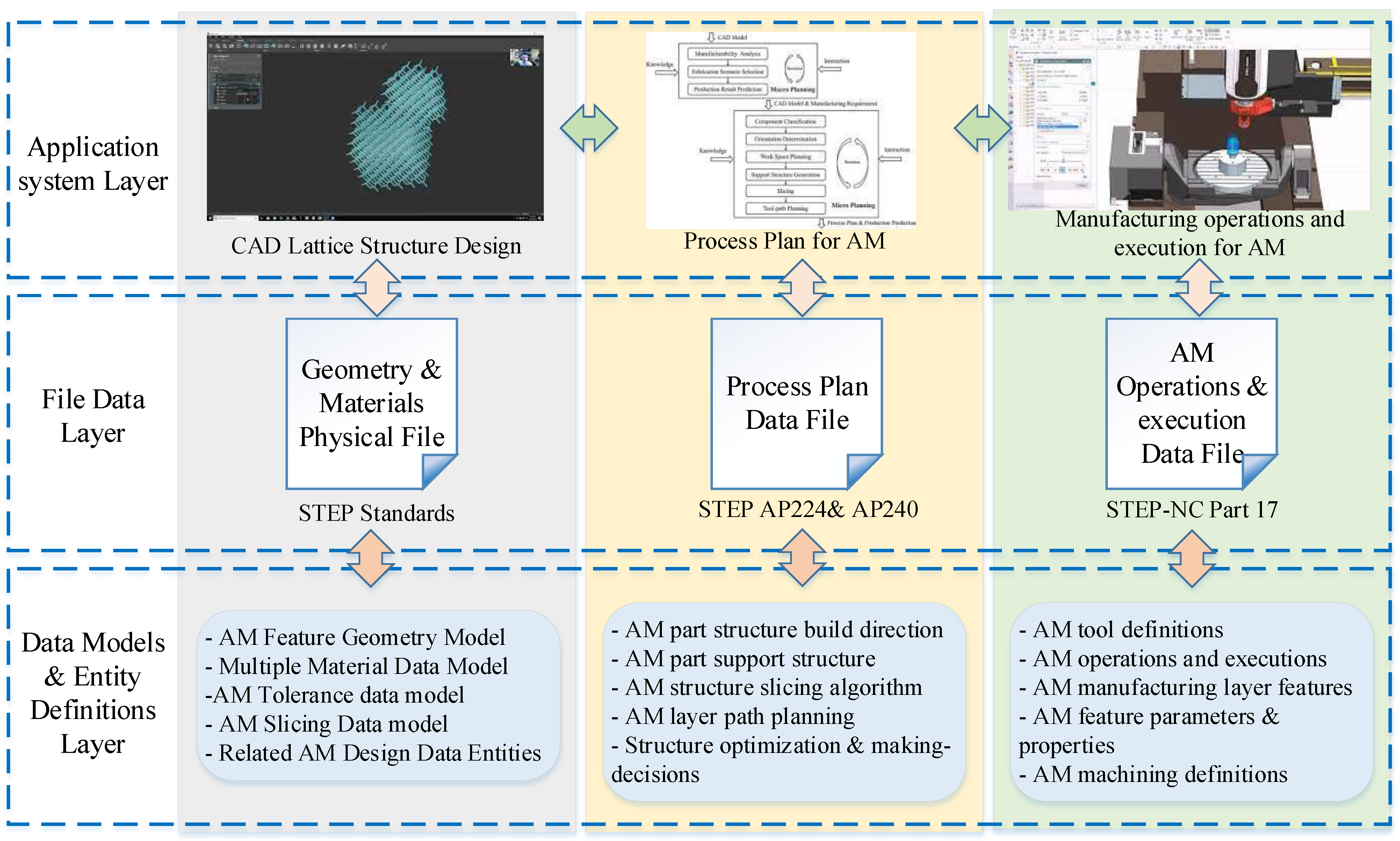
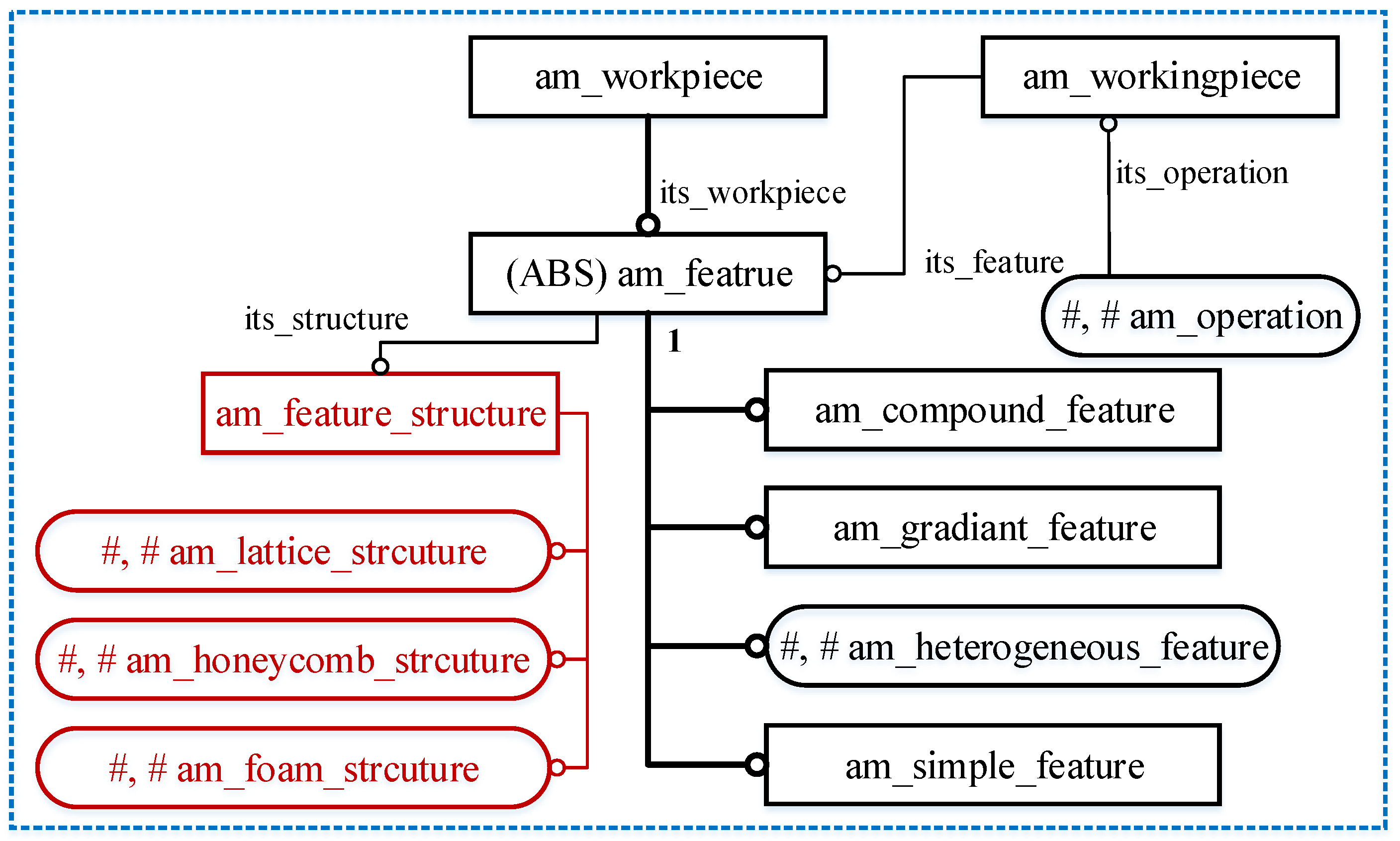
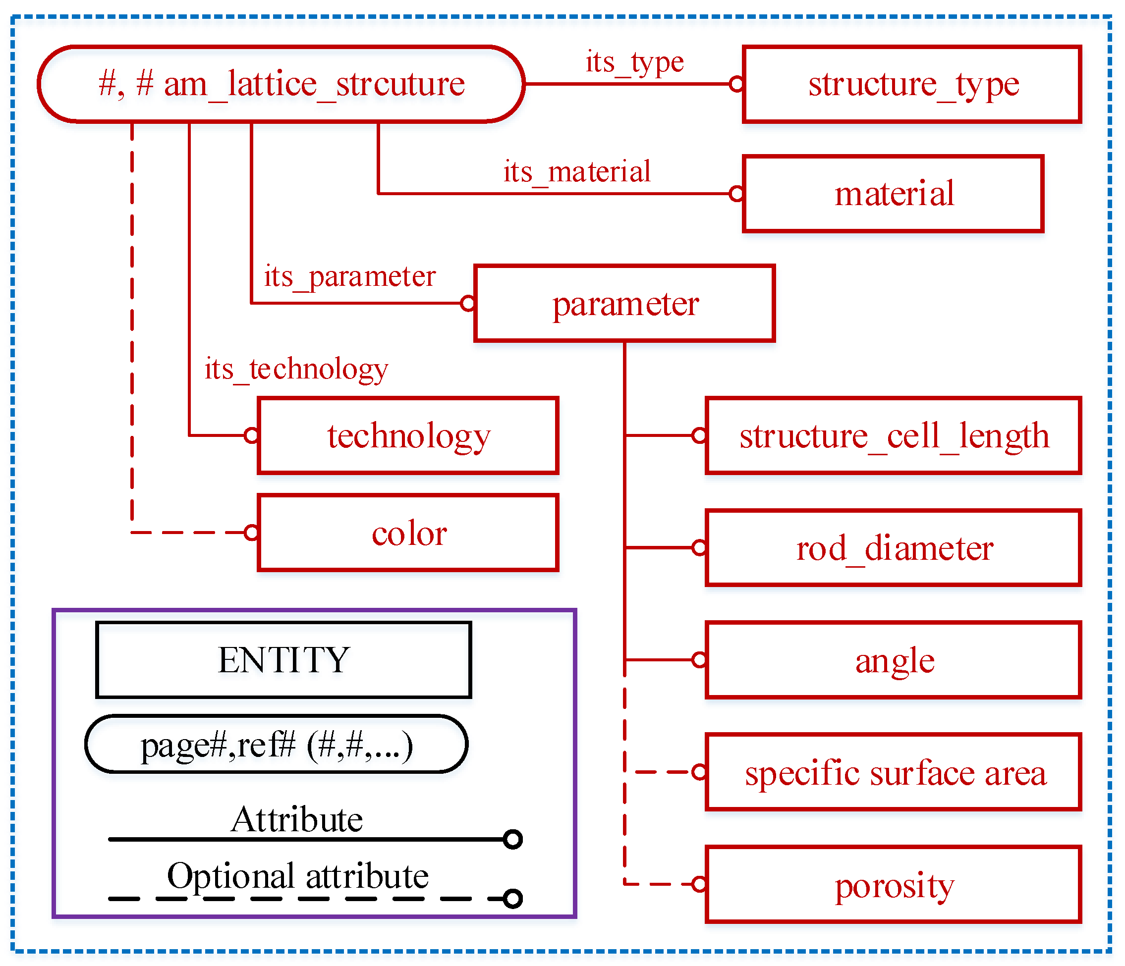
  • There is no data model to represent the AM geometry features, such as a lattice structure, honey structure, foam structure, etc. Therefore, the related data model needs to be proposed based on the current STEP-NC Part 17 to complete the syntax and semantics of the AM feature definitions.
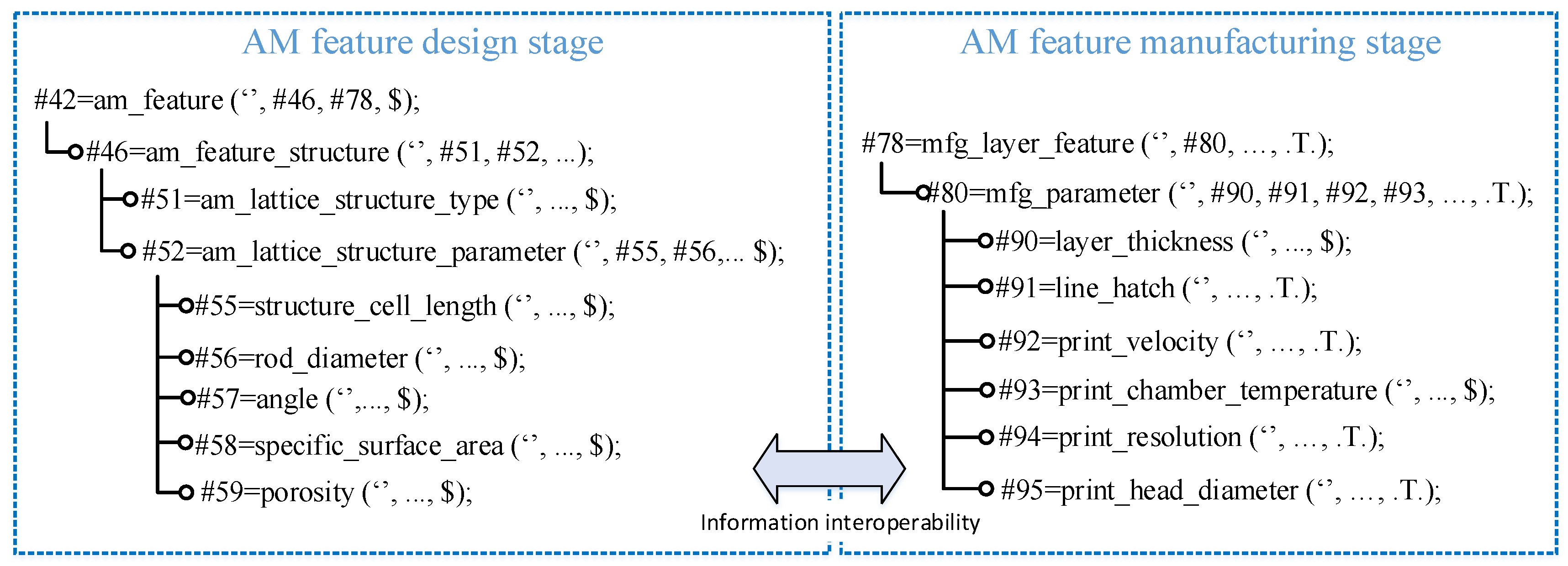
  • Owing to the complexity of the loads of the AM feature data entities, it will cause poor compatibility and interoperability when they are transferred in different application systems. Therefore, it is necessary to integrate the information of the AM features in the CAD/CAPP/CAM/CNC systems, which can be easily transferred without any mistakes and redundancies.
In order to accomplish the high efficiency of the data exchange, the AM feature information needs to redefine and propose the compatible data model to represent the design and manufacturing information of the AM features. Next, we will introduce the manufacturing feature and process parameters for AM in Section 2. An extended STEP/STEP-NC-compliant data model will be presented in Section 3. We will give a discussion about the conformance analysis and implementations for a specific application in Section 4. Finally, the conclusion will be given.

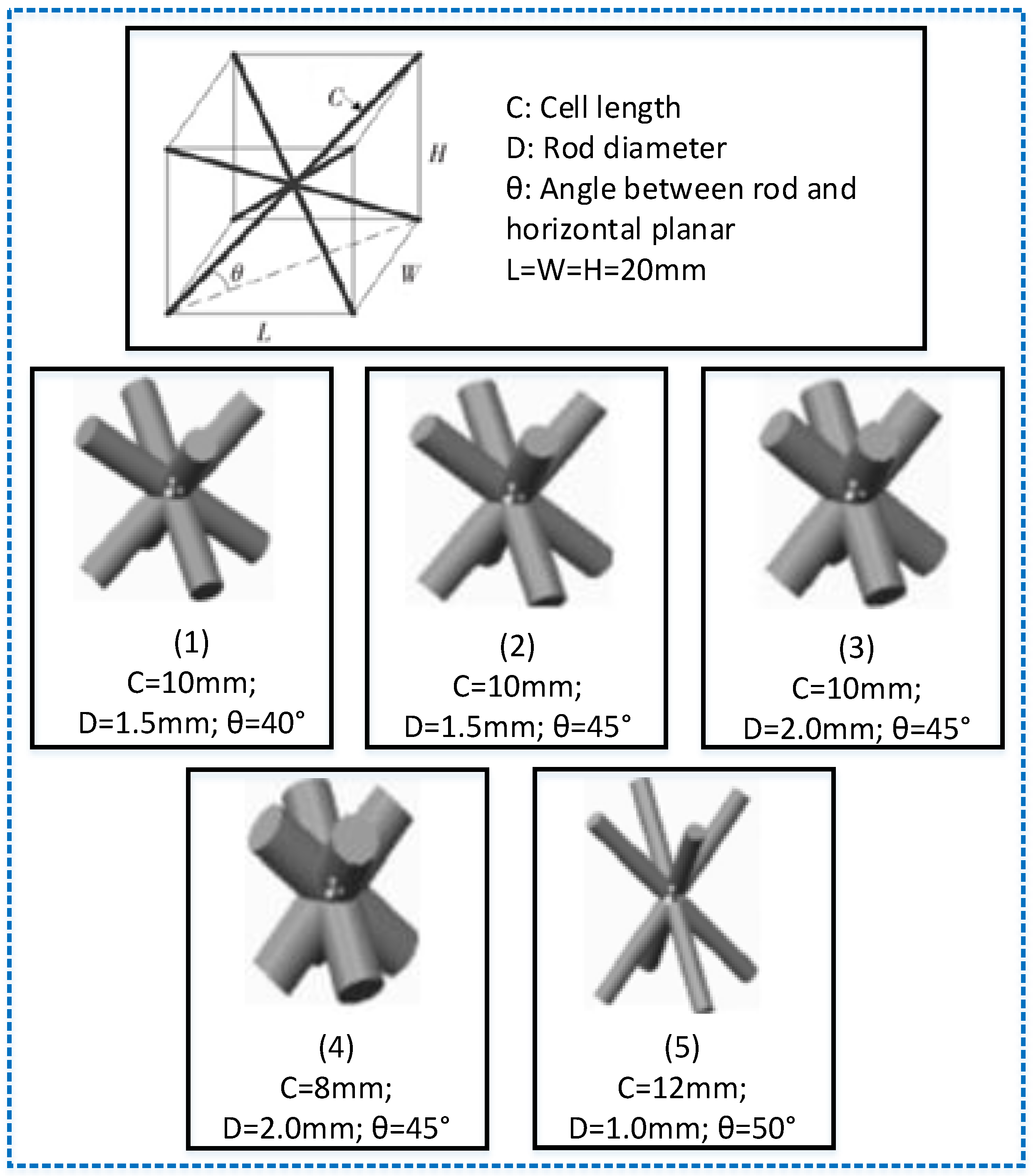
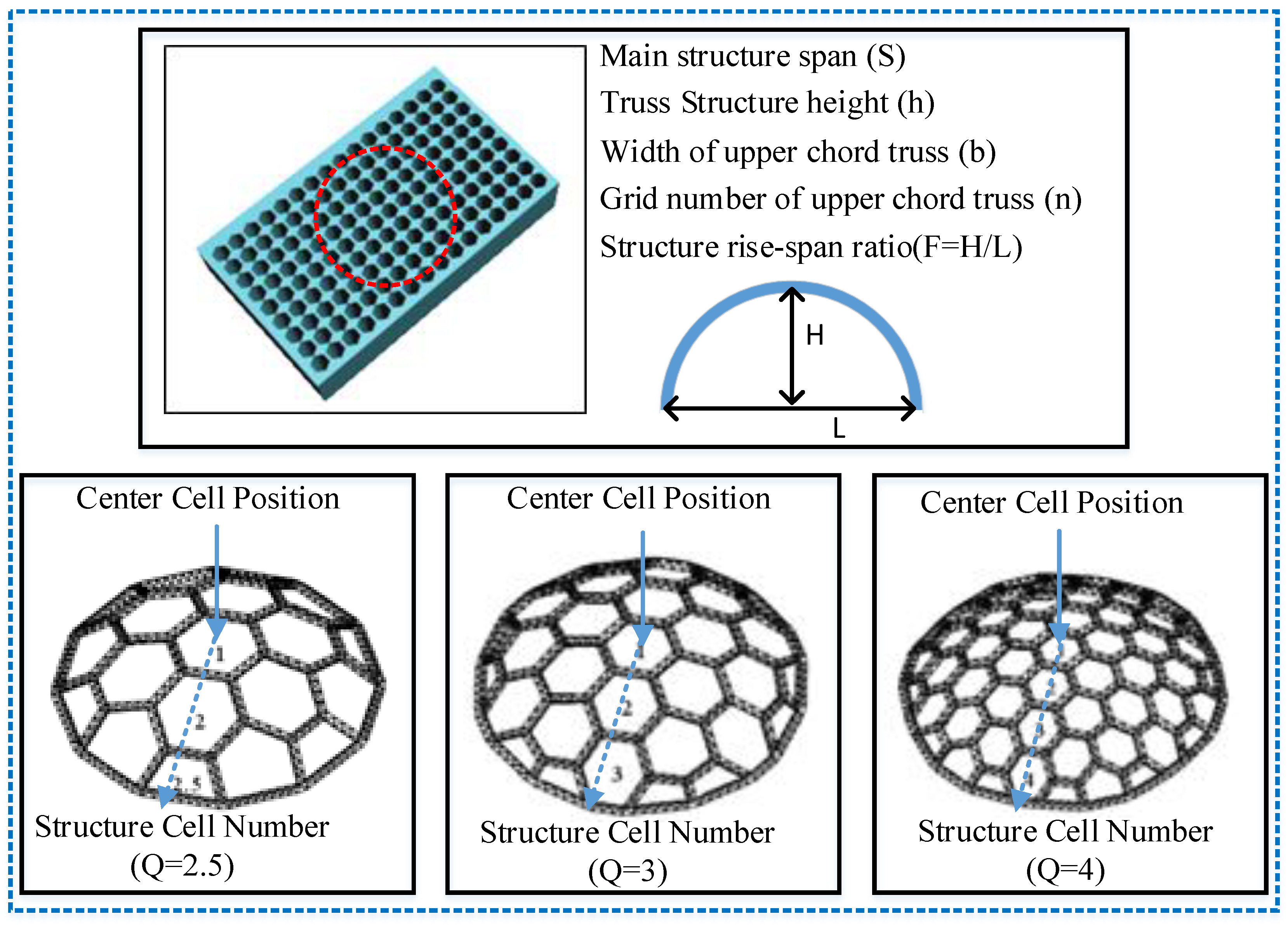
2. Manufacturing Features and Parameters

According to the particularity of the geometry feature and structure in AM, we can summarize the specific AM features into a lattice structure, honeycomb structure, foam structure, and general geometry structure. Owing to the complexity of the manufacturing features in the AM process, it is necessary to define its parameters and properties in actual application. However, its properties have little involvement in specifying the manufacturing features that we will give more attention to in the manufacturing features and parameters. As shown in Figure 1, the AM design and manufacturing information architecture can be built to describe the data interoperability from the design application system and process planning system to the manufacturing execution system. In the application systems, we need to extend the data models and related entity definitions to enrich the contents of the AM data files. Owing to the specific AM feature in design and manufacturing, it is necessary to define the AM feature information in various application stages that can make it easier to accomplish the high-efficiency data transfer.
As mentioned above, it is necessary to focus on the extent of the STEP/STEP-NC-compliant data models and the entities definitions for the AM geometry features and manufacturing features. Therefore, we need to discuss the research on different AM features, such as the lattice structure, honey structure, and foam structure, which will pay more attention to its parameters and properties in the real design and manufacturing stages. However, we know that the lattice structure is a lattice truss structure, including panels, bars, and other elements. It can realize functional design through the related parameters and geometric size for each cell. It is characterized by a light weight, high specific strength, and low density. The lattice structure includes many similar structures, including the Octet-truss lattice structure, 3D Kagome lattice structure, triangular sandwich lattice structure, etc. Generally, we can establish the spatial structure through the panel and rod element and define the related parameters, such as the cell length, rod diameter, and the angle between the rod and the horizontal plane, as shown in Figure 2. Furthermore, the rod element structure can be generated, and the parameters of the cell rod can be defined by the optimal design. The fundamental structure of a rod cell can be periodically generated into an array according to specific design rules. By adjusting various parameters of the lattice structure cell, the micro geometry model can be obtained with different, specific surface area and porosity.
As known, we can calculate the specific surface area and porosity of various parameters for the specific lattice structure. Therefore, the specific design parameters can be used to optimize the desired structure according to the related requirements and application scenario. For example, the high porosity of the lattice structure can be used to reduce the volume of the printing materials in order to ensure the physical performances and requirements in lightweight application and design. Similarly, the honeycomb structure includes multiple honeycomb units by a seal material layer; each honeycomb unit has multiple holes that are arranged side by side in a longitudinal direction and separated from each other. It is known that the 3D honeycomb structure is composed of the main hexagonal structures and substructures, which is characterized by the advantages of averaged scattered stress, high bearing capacity, structure stability, and material saving. However, we know that the main structure design defines the number of structure cells (Q), the main structure span (S), the rise-to-span ratio (F), the 3D truss height (h), the upper chord width (b) of the 3D truss structure, and the grid number of the upper chord (n), as shown in Figure 3. We know that the main structure span defines the size of the printing area for the manufacturing features of the print part. According to the specific requirements of a 3D structure, we can optimize and obtain the related parameters under the design constraints. Based on the optimal parameters of the main structure, the corresponding honeycomb structure information can be generated and finally obtain a complete cellular honeycomb structure model.
The foam structure is formed by the structure with stomata. The formation of pores is an important factor in the manufacturing process that determines the related parameters of size, location, and thickness in the foam structure. We know that structure parameters will affect the performance of the foam structure. The characteristics of the foam structure are lightweight, efficient, and broadband microwave absorbing properties. When we design the foam structure in a certain space, solid model parameters firstly need to be ensured, including the pore position, pore diameter, pore trajectory, etc. Owing to the complexity of foam structure manufacturing, the foam structure parameter needs to integrate more information to support the optimal formation of the foam structure. However, apart from the lattice structure, honeycomb structure, and foam structure, we should also consider a general layer structure as a manufacturing feature in AM. The general layer structure can be represented by STEP IRs’ standards that define the contour, line, and curve and even the layer thickness by a STEP-compliant data model [14]. However, we know that the particular AM features need to be extended for their application objects and data entities. The manufacturing process parameters in specific AM technology are very important as they affect the information interoperability in various application systems. Therefore, we need to consider the manufacturing features and process parameters for the specific information exchange and sharing.

3. Extended STEP-Compliant Data Model

Additive manufacturing technology as a supplementary manufacturing method can be used to fabricate some particular structure, such as a lattice structure, honeycomb structure, foam structure, etc. Owing to the advantages of the AM printing structure, it can provide the least materials to ensure the physical performance and structure stability in engineering application. By comparing the differences between AM processes and traditional manufacturing, the particular structures for AM could be a better manufacturing technology that can make it easier to accomplish the complex part manufacturing. However, the particular structures for AM need to redefine them as AM features that provide the manufacturing information for specific AM operations. We referred to the related standard known as the ISO 14649 Part 17 additive manufacturing data model that has defined the related AM features, but it is necessary to enrich the semantics and syntax of the particular structure as an AM geometry and printing feature rather than only considering a heterogeneous feature [15]. We know that traditional manufacturing considers the machining features (i.e., round hole, pocket, slot, planar face, etc.), which are mainly used to specify the machining methods and strategy according to the geometry and shape features. Similarly, when we consider the AM geometry and shape features, the particular structures (lattice structure, honeycomb, foam, etc.) are necessary to deeply discuss its information integration and parameter representation [16]. Therefore, it is necessary to propose the extended STEP/STEP-NC-compliant data model to represent the information interoperability of the AM features and its structure parameters as shown in Figure 4.
In order to easily solve the information interoperability for AM special geometry structures, we extend their related parameter information to specify the data models and a conformance analysis in actual information exchange and sharing [17]. AM features can be generated by adjusting the related parameter information and automatically transferring the structure data to downstream manufacturing. We know that the lattice structure is broadly used to reduce the printing material volume in order to keep the physical performance in industrial applications. However, we know that the lattice structure is very popular in the actual AM printing structure. Therefore, it is important to represent its extended data entities and application objects for various application systems.
As shown in Figure 5, we define the entity of the lattice structure in AM, which includes the information of various materials, related colors, structure types, related parameters, and even the AM function and technology. However, the structure parameters have huge effects on manufacturing planning and specific printing operations in AM, which specify the information of the structure cell length, the rod diameter of the lattice structure, the angle between the structure rod and cell planar, and even the specific surface area and porosity. Many researchers have proposed the evaluation of structural element parameters for each lattice structure [18], such as the elastic module, ultimate strength, stiffness, strut diameter, strut length, joint diameter, etc. Furthermore, it is also very necessary for an AM process to consider the relationships between the feature parameters and process parameters, which can affect the final determination of the AM feature structure in the AM printing process. The lattice structure, as one of the most popular AM feature structures, can provide an efficient solution to AM technology to accomplish the high performance of an AM printing part. Therefore, it is necessary to define its related data model to support the data exchange and sharing. Similarly, honeycomb and foam structures can also build related data models to facilitate the information interoperability in various application systems. In terms of the honeycomb structure, we know that honeycomb can be divided into a planar and curve surface structure, which the former can easily be fabricated by traditional manufacturing technology and the latter might consider more AM technology. Therefore, it is necessary to consider the honeycomb as the AM feature structure in the actual manufacturing process. As shown in Figure 3, we know the related parameters of the honeycomb structure (i.e., main structure span, truss structure height, width of upper chord truss, grid number of upper chord truss, structure rise-to-span ratio, etc.), which finally determines the specific honeycomb structure by specifying the defined parameters in the AM feature structure design. Certainly, the foam structure can also be determined by optimizing the related parameters in the design process, which can be transferred to the manufacturing process to provide the printing data. In summary, the AM feature structure (i.e., lattice structure, honeycomb structure, foam structure, etc.) can be used as peculiar AM features to represent the product design and manufacturing parameter information of the structure from the product design and process planning to the manufacturing stage.

4. Conformance Analysis and Implementation

The conformance analysis and implementation of the data model should be considered to verify the information interoperability between various application systems. The functional requirements of the data model determine its conformation analysis that supports all of its functions for each entity or application object for the information transfer when certain an entity is executed from one system to another. As known, the lattice structure parameters include the fundamental information of the design structure to determine the manufacturing process parameters according to the intelligent algorithms. For example, the rod diameter of a lattice structure determines the physical property of the printing structure, which affects the print thickness, print resolution, print head diameter, etc., under the requirements of the printing quality. The conformance analysis considers more functional requirements for each entity in the actual information interoperability, which ensure the correct and complete data transfer of each of the entity data in various application systems. Therefore, each entity can be correctly transferred to another system and keep its original functions completely. However, it is a huge project to verify and validate its conformance analysis for each entity, which can be used to partially assess its functional requirements in the system interoperability process. Moreover, the implementation of data models is an efficient way to evaluate the correctness of the proposed data models. However, it is impossible to completely verify the implementation of a data model without any test platform that can support the function of each defined entity in the interoperability system. Therefore, it becomes a necessary process to deduce the interoperability process based on the data exchange methods.
As shown in Figure 6, the implementation of an AM feature for the lattice structure is accomplished by the related data model and STEP Part 21 language to represent the related information in product design and manufacturing. The AM feature includes various applied structures for AM that are used to reduce the material volumes of print parts while ensuring its physical performance in AM. However, a conformance analysis for AM feature information mainly focuses on the corrected data transfer and the completed data representation. All defined parameter data can be correctly transferred and there are not any mistakes for all the defined entities in the various application systems. For specific information interoperability, the structure design information actually determines the manufacturing parameters that can be calculated by various optimization methods. Therefore, the implementation of AM feature information should be transferred by a STEP physical file to downstream manufacturing that provides the related data entities and parameter data in application manufacturing systems [19]. The implementation is to focus on the executions of the printing process and the operations of print tools that specify the functions of each entity and application object. However, the real implementation for AM feature information is a huge feat of engineering to accomplish all the data interoperability in the various application systems, which needs to create the test tools and related software. Therefore, the demonstration of AM implementation provides the possibility of transferring all the related data functions without any information loss or mistakes. In summary, the conformance analysis and the implementation of the data model mainly accomplish the verification and validation of the functional data entities and application objects in interoperable application systems.

5. Discussion

The data model of the AM features has been extended to represent the relationships between the data entities and their related definitions, which can provide an information system framework for all specific AM features that can be easily transferred to downstream manufacturing with high efficiency and compatibility. The proposed data model can represent the data of the geometry feature parameters and its properties. In addition, it is necessary to verify its conformance for all the defined data entities that determines the correctness and completeness of the proposed data models. In order to simplify the conformance process for all the related data entities and models, the conformance analysis can be deduced by analyzing the related functions of each entity. However, we know that it is difficult to verify all the defined entities without any test tools and an application platform. Therefore, we will discuss the future development and possible further research points.
  • The implementation of the STEP/STEP-NC-compliant data model for AM features needs to build the platform of the application system. As known, STEP-NC Part 17 does not have enough to define the special AM features to support the high-efficiency data interoperability that can directly select the suitable AM features according to the product design requirements. Therefore, the future development for our proposed method will improve the intelligence and compatibility of CNC machining for AM features.
  • The requirements of the AM information integration and intelligent application make the proposed models necessary to develop a knowledge application system that can help designers or manufacturers determine the selection of the AM features with respect to the product or customer requirements. For further research, by combining an ontology-based modeling method and STEP/STEP-NC data models, the intelligent knowledge application system can further enhance the ability of data transfer and system decision making [20].
In a word, the proposed data models for special AM features have huge meanings to further explore the high-efficiency data interoperability and system integration. However, it is also necessary to develop an intelligent AM machining system that needs to integrate the related data models, including AM geometry features, manufacturing features, etc.

6. Summary

In this paper, we proposed the method of an extended data model to enrich the information of AM feature and process parameters based on STEP/STEP-NC standards, which specifies the information of data entities and application objects for an AM feature structure. We deeply analyzed the special AM structure and the related parameters, including the lattice structure, honeycomb structure, and foam structure, which are broadly applied in aerospace and automatic manufacturing fields. Furthermore, we extended the STEP/STEP-NC-compliant data model for AM features that detailed the information of the lattice structure and its parameters. Finally, the conformance analysis and implementation of the proposed data model for the lattice structure was simply explained by its related functional requirements and the STEP Part 21 physical file.

Author Contributions

Conceptualization, J.X. and Y.L.; methodology, J.X.; software, J.X.; validation, J.X. and Y.L.; formal analysis, J.X.; investigation, J.X.; resources, J.X.; data curation, J.X.; writing—original draft preparation, J.X.; writing—review and editing, J.X.; visualization, J.X.; supervision, J.X.; project administration, J.X.; funding acquisition, J.X. and Y.L. All authors have read and agreed to the published version of the manuscript.

Funding

This research received no external funding.

Institutional Review Board Statement

Not applicable.

Informed Consent Statement

Not applicable.

Data Availability Statement

Not applicable.

Conflicts of Interest

The authors declare no conflict of interest.

References

  1. Kim, D.B.; Witherell, P.; Lipman, R.; Feng, S.C. Streamlining the additive manufacturing digital spectrum: A systems approach. Addit. Manuf. 2015, 5, 20–30. [Google Scholar] [CrossRef]
  2. Williams, C.B.; Simpson, T.W.; Hripko, M. Additive Manufacturing Technical Workshop Summary Report NIST Technical Note 1823 Additive Manufacturing Technical Workshop Summary Report. In Proceedings of the ASME Design Engineering Technical Conferences—Design Education Conference, St. Louis, MI, USA, 2 August 2015; pp. 1–59. [Google Scholar]
  3. Xiao, J.; Eynard, B.; Anwer, N.; le Duigou, J.; Durupt, A. Geometric Models and Standards for Additive Manufacturing: A Preliminary Survey. In Proceedings of the Virtual Concept International Workshop-major Trends in Product Design, Bordeaux, France, 12 September 2016. [Google Scholar]
  4. Bonnard, R.; Hascoët, J.-Y.; Mognol, P.; Stroud, I. STEP-NC digital thread for additive manufacturing: Data model, implementation and validation. Int. J. Comput. Integr. Manuf. 2018, 31, 1141–1160. [Google Scholar] [CrossRef]
  5. Rodriguez, E.; Alvares, A. A STEP-NC implementation approach for additive manufacturing. Procedia Manuf. 2019, 38, 9–16. [Google Scholar] [CrossRef]
  6. Lu, Y.; Choi, S.; Witherell, P. Towards an Integrated Data Schema Design for Additive Mnaufacturing: Conceptual Modeling. In Proceedings of the IDETC/CIE Conference, Boston, MA, USA, 2–5 August 2015; pp. 1–11. [Google Scholar]
  7. Um, J.; Rauch, M.; Hascoët, J.Y.; Stroud, I. STEP-NC compliant process planning of additive manufacturing: Remanufacturing. Int. J. Adv. Manuf. Technol. 2016, 31, 1141–1160. [Google Scholar] [CrossRef]
  8. Wang, Z.; Liu, P.; Xiao, Y.; Cui, X.; Hu, Z.; Chen, L. A Data-Driven Approach for Process Optimization of Metallic Additive Manufacturing under Uncertainty. J. Manuf. Sci. Eng. Trans. ASME 2019, 141, 081004. [Google Scholar] [CrossRef]
  9. Habib, M.A.; Khoda, B. Attribute driven process architecture for additive manufacturing. Robot. Comput. Integr. Manuf. 2017, 44, 253–265. [Google Scholar] [CrossRef]
  10. Zhang, Z.; Joshi, S. Slice data representation and format for multi-material objects for additive manufacturing processes. Rapid Prototyp. J. 2017, 23, 149–161. [Google Scholar] [CrossRef]
  11. Ding, D.; Pan, Z.; Cuiuri, D.; Li, H.; Larkin, N.; van Duin, S. Automatic multi-direction slicing algorithms for wire based additive manufacturing. Robot. Comput. Integr. Manuf. 2016, 37, 130–150. [Google Scholar] [CrossRef]
  12. Zhou, M.Y. STEP-based approach for direct slicing of CAD models for layered manufacturing. Int. J. Prod. Res. 2005, 43, 3273–3285. [Google Scholar] [CrossRef]
  13. Witherell, P. Toward Metamodels for Composable and Reusable Additive Manufacturing Process Models. J. Manuf. Sci. Eng. 2014, 136, 105–126. [Google Scholar] [CrossRef]
  14. Xiao, J.; Eynard, B.; Anwer, N.; Durupt, A.; le Duigou, J.; Danjou, C. STEP/STEP-NC-compliant manufacturing information of 3D printing for FDM technology. Int. J. Adv. Manuf. Technol. 2021, 112, 1713–1728. [Google Scholar] [CrossRef]
  15. ISO 14649 Part 17; Industrial Automation Systems and Integration—Physical Device Control—Data model for computerized numerical controllers—Part 17: Process data for additive manufacturing. ISO: Geneva, Switzerland, 2018.
  16. Xiao, J.; Anwer, N.; Durupt, A.; le Duigou, J.; Eynard, B. Definition, parameterisation and standardisation of machine-specified data process in additive manufacturing, Advances in Manufacturing Technology XXXI. In Proceedings of the 15th International Conference on Manufacturing Research, Incorporating the 32nd National Conference on Manufacturing Research, London, UK, 5–7 September 2017. [Google Scholar]
  17. Xiao, J.; Durupt, A.; le Duigou, J.; Anwer, N.; Eynard, B. STEP-based Process Information Models for Additive Manufacturing: Application to Fused Deposition Modelling. Dyna 2019, 94, 197–202. [Google Scholar] [CrossRef]
  18. Park, S.I.; Rosen, D.W.; Choi, S.k.; Duty, C.E. Effective mechanical properties of lattice material fabricated by material extrusion additive manufacturing. Addit. Manuf. 2014, 1, 12–23. [Google Scholar]
  19. Xiao, X.; Roh, B.M.; Hamilton, C. Porosity management and control in powder bed fusion process through process-quality interactions. CIRP J. Manuf. Sci. Technol. 2022, 38, 120–128. [Google Scholar] [CrossRef]
  20. Roh, B.M.; Kumara, S.R.; Witherell, P.; Simpson, T.W. Ontology-based process map for metal additive manufacturing. J. Mater. Eng. Perform. 2021, 30, 8784–8797. [Google Scholar] [CrossRef]
Figure 1. AM design and manufacturing information architecture based on various data layers.
Crystals 12 01154 g001
Figure 2. Comparison of different parameters for lattice structure.
Crystals 12 01154 g002
Figure 3. Honeycomb structure and related parameters.
Crystals 12 01154 g003
Figure 4. Extended STEP-compliant AM feature data model [15].
Crystals 12 01154 g004
Figure 5. Data model for lattice structure based on EXPRESS-G.
Crystals 12 01154 g005
Figure 6. STEP physical file for AM feature design and manufacturing.
Crystals 12 01154 g006
Publisher’s Note: MDPI stays neutral with regard to jurisdictional claims in published maps and institutional affiliations.

