Article

Electrochemical Discharge Behavior of As-Cast Mg-x Sn Alloys as Anodes for Primary Mg-Air Batteries

1
Key Lab of Electromagnetic Processing of Materials, Ministry of Education, Northeastern University, Shenyang 110819, China
2
College of Chemistry and Material Science, Longyan University, Longyan 366300, China
3
Fujian Key Laboratory for Rare Earth Functional Materials, Longyan 366300, China
4
College of Materials Science and Engineering, Shenyang University of Technology, Shenyang 110870, China
*
Author to whom correspondence should be addressed.
Crystals 2022, 12(8), 1053; https://doi.org/10.3390/cryst12081053
Submission received: 22 June 2022 / Revised: 21 July 2022 / Accepted: 25 July 2022 / Published: 28 July 2022
(This article belongs to the Special Issue State-of-the-Art Magnesium Alloys)

Abstract

:
The microstructural characteristics of cast Mg-x Sn (x = 0.5, 1.0, 2.5 wt.% and 4.0 wt.%) alloys were systematically evaluated, as well as the electrochemical behavior and discharge properties in 3.5 wt.% NaCl solution. The micro-morphological results show that the grains are obviously refined and the Mg2Sn phase distribution is uniform with the increase of Sn content. In the four tested alloys, the effect of Sn content on the corrosion resistance of the alloys was found to be bidirectional by using the loss-in-weight method and electrochemical measurements. Among them, Mg-2.5Sn exhibits higher corrosion resistance in 3.5 wt.% NaCl solution. The decrease of the self-corrosion rate of Mg-x Sn alloy is mainly due to the formation of a SnO2 protective film, which inhibits the expansion of pitting corrosion. In addition, an appropriate amount of Mg2Sn can weaken the self-corrosion behavior. Mg-1Sn exhibits the highest anode efficiency and discharge capacity of 56.11% and 1245.72 mAh·g−1, respectively. Mg-0.5Sn shows the highest peak energy density, which is 1258.78 mWh·g−1.The maximum average discharge voltage of Mg-2.5Sn is 1.461 V.

1. Introduction

With the increase of world energy consumption, the emissions of carbon dioxide, dust particles, nitrogen oxides and other environmental pollutants increase. The impact of fossil energy on environmental pollution and climate change will become more and more serious. Therefore, in order to solve the above energy problems, researchers are looking for and developing low-cost, high-efficiency, pollution-free, safe and reliable energy storage systems [1,2]. The metal–air battery is a good choice. The anode is metal alloy and the cathode is oxygen in the air. Therefore, the weight of the battery can be reduced to make room for energy storage. Compared with the lithium (Li)-air battery, the zinc (Zn)-air battery and the aluminum (Al)-air battery, the primary magnesium–air battery is a promising power supply [1,3], because of its high reaction activity, low toxicity, high safety and low density [1,2,4,5,6].
However, the self-corrosion, corrosion and bulk effect of the magnesium anode discharge process may cause capacity loss [2,7,8,9,10]. These are all factors that limit the application of magnesium–air batteries. Alloying is one of the most effective means to improve the performance of magnesium–air batteries. Chen et al. [11] reported that a Mg-0.5Bi anode shows excellent discharge performance. A magnesium–air battery using Mg-0.1wt.% Ca alloy as an anode provides higher cell voltage and specific energy than high-purity Mg, AM50 and AZ31 alloys [12]. The corrosion resistance and discharge properties of Mg-2Zn alloy were reported to be higher than those of recast magnesium [13]. Therefore, there is a continuing need to develop environmentally friendly, low-cost anodes with high discharge activity and anode efficiency.
In recent years, the addition of Sn to magnesium has attracted great attention. Sn element can easily combine with Mg to form a thermally stable Mg2Sn phase. It can promote the formation of micro-cracks on the surface of the alloy during the discharge process, enhance the reactivity of the alloy, realize the self-stripping of the discharge product, act as an activation point to promote the dissolution of the magnesium anode, and finally improve the discharge activity [14,15,16]. However, too much Mg2Sn phase will lead to severe self-corrosion [17,18], which significantly reduces the anode efficiency. Tong et al. [19] studied the discharge performance and electrochemical behavior of as-cast Mg-Sn binary alloys, and found that Sn can improve the overall performance of magnesium anodes, and used impedance modulus to evaluate its corrosion resistance. Generally, Mg-5Sn has the highest impedance modulus and the best corrosion resistance. Han et al. [20] concluded that the best performance and corrosion resistance is achieved for the Mg-1Sn anode. The weight loss, hydrogen evolution, and electrochemical measurements carried out by Yu et al. [21] indicated that Mg-3Al-1Sn had a low corrosion rate. Song et al. [22] found that AM70 magnesium alloy with 2 wt.% Sn addition is more prone to uniform corrosion, but the corrosion resistance of AT72 is worse according to weight loss and hydrogen evolution measurements. Yang et al. [23] showed that Mg-5Sn has higher corrosion resistance than Mg-2Sn, which was attributed to the Sn-rich layer. It could decrease the cathode hydrogen evolution rate, and help to improve corrosion resistance. A study by Jiang et al. [24] found that the effect of Sn addition on the corrosion performance of Mg-4Zn alloys is bidirectional. Li et al. [25] studied four as-cast Mg-xSn alloys, and the Mg-1.5Sn alloy had the best corrosion resistance due to the formation of Mg(OH)2 /SnO2 corrosion product films and Mg(OH)2 /MgSnO3 clusters, in which Mg(OH)2/MgSnO3 clusters are dense, which greatly inhibits the cathodic effect of impurity inclusions. Xiong et al. [26] found that the Mg-6Al-1Sn anode material has excellent discharge performance.
However, the effect of Sn content on the electrochemical behavior and the discharge performance of Mg-Sn binary alloys is not clear. The purpose of this work is to investigate the effect of increasing Sn content on the microstructure, corrosion behavior, and discharge performance of the Mg-Sn-based anodes. This research can provide some basis for the performance optimization of Mg-Sn-based alloys as anode materials in the future.

2. Experimental Procedures

2.1. Materials

The magnesium anode materials used in this experiment are all as-cast magnesium alloys, and Mg-x Sn (x = 0.5, 1, 2.5, 4.0 wt.%) binary alloys are prepared by melting and casting. Before smelting, ensure that the surface of ingredients is clean to avoid introducing sundries and moisture. During smelting, the resistance furnace temperature was set to 973 K, and under the protection of CO2 and SF6 gas, pure Mg (99.99%) and an appropriate amount of pure Sn (99.99%) were melted in a graphite crucible in the resistance furnace. After the metal in the crucible is completely melted, the slag is removed, and it is fully stirred, and then allowed to stand for 10–15 min to ensure its uniformity. The molten metal is poured into the mold under a protective atmosphere. After the smelting, two strip-shaped blocks were obtained at the upper, middle and lower positions of the obtained ingot, and then the chemical composition of the alloy was detected by using an inductively coupled plasma analyzer. The composition of the upper, middle and lower positions of the ingot is uniform. The chemical compositions of the alloys were listed in Table 1.

2.2. Microstructure

Specimens for microstructure analysis need to be ground and polished, and etched in picric acid. The microstructure of the magnesium alloy was observed by optical microscopy (OM, DMI5000M, Leica, Wetzlar, Germany) and the grain size was counted in combination with Image-proplus software. The phase structure of each magnesium alloy electrode was analyzed by X-ray diffractometer (XRD, X Pertpro, Japan Shimadzu Co., Ltd., Tokyo, Japan). In addition, the surface morphology of the samples was examined by scanning electron microscopy (SEM, Quanta 250 FEG, FEI Ltd., Eindhoven, The Netherlands) and the composition was characterized by X-ray energy spectrometry (EDS, JXA-8530F, Jieou Road Technology and Trade Co., Ltd., Beijing, China). The samples after immersion testing were also analyzed by X-ray photoelectron spectroscopy (XPS, Kratos-Axis Supra, Manchester, UK).

2.3. Electrochemical Tests

The experiment samples were cut into small squares of 10 × 10 × 10 mm3 in size. Samples for electrochemical testing also needed to be ground to 4000 mesh (to reduce the effect of scratches on the surface area of the sample). ChenHua CHI660E (Shanghai, China) electrochemical workstation was used for the electrochemical testing of magnesium alloy anode, using a three-electrode system, in which the working electrode is the magnesium alloy anode, a platinum electrode was the counter electrode, and the reference electrode is saturated calomel electrode (SCE). The tests were conducted in 3.5 wt.% NaCl at room temperature, and included testing of the open circuit potential (OCP), electrochemical impedance spectra (EIS) and potentiodynamic polarization. First, the working electrode is soaked in solution for 3600 s, a stable open circuit potential can be obtained, followed by the electrochemical impedance spectra test, and the frequency range should be set to 100 kHz–10 mHz. Before the polarization curve test, the instantaneous open-circuit potential value should be recorded, and then the voltage amplitude should be set to 0.5 V and the scan rate to 1 mV s−1. Equivalent circuit and electrochemical parameters are obtained by fitting the EIS curve using ZSimpWin software (AMETEK SI, Berwyn, Pennsylvania, USA). Tests for weight loss were performed by first immersing the alloy samples in 3.5 wt.% NaCl solution at 25 °C for 110 h. Then, samples were soaked in solution of 20% CrO3 for 10 min to remove corrosion products. Finally, samples were cleaned in alcohol, then dried in air and weighed. The above tests were performed at least five times to ensure repeatability of the results.

2.4. Mg-Air Battery Tests

The NEWARE battery test system (Belleville, IL, USA) can be used to test the performance of magnesium alloy batteries. The preparation of magnesium alloy anode is the same as that of magnesium alloy anode in an electrochemical test. The discharge curve was measured at room temperature, and a constant current density of 1, 2, 5, 10, 20, 40, and 80 ma cm−2 was applied to the magnesium anode during 10 h discharge to measure the change of discharge voltage. Samples after discharge were soaked in solution of 20% CrO3 for 10 min to remove discharge products. The above tests at least three times to ensure repeatability of the results. The discharge morphology was also observed using SEM.

3. Results and Discussion

3.1. Microstructures

Figure 1 shows the optical micrographs of the Mg-x Sn alloys and average grain size statistics. The Sn contents of the alloys were 0.5, 1, 2.5 and 4 wt.%, respectively, and the average grain size decreased from 595.795μm to 508.631 μm, 281.784 μm and 154.185 μm. When the Sn content is ≤1 wt.%, the second phase is hardly seen, and when the Sn content is ≥2.5 wt.%, the distributed second phase can be seen on the grain boundaries and inside the grains.
The XRD results are shown in Figure 2. All four alloys studied contain only α-Mg and Mg2Sn phases. It can be observed from the figure that the intensity of the Mg2Sn phase peaks of Mg-0.5Sn and Mg-1Sn alloys is relatively weak, and it increases gradually with the increasing Sn content. To further confirm the phase composition of the experimental alloys, the morphologies and compositions of the Mg-2.5Sn and Mg-4Sn alloys were examined by SEM and EDS. Figure 3 presents SEM images of Mg-2.5Sn and Mg-4Sn anode, and chemical composition at different positions analyzed by EDS. These are the strips and balls Mg2Sn phase, the chemical composition of which is identified by the EDS, and shown in Figure 3f,j,h,l (Points A, B, C and D). Furthermore, it can be seen from Figure 3a,c that most of the Mg2Sn phase is distributed on the grain boundaries. The distribution of Mg2Sn phase in Mg-2.5Sn is relatively dispersed, while the Mg2Sn phase of Mg-4Sn forms a continuous network. At the same time, the more Mg2Sn phase, the more obvious grain refinement effect.

3.2. Polarization Behavior

The polarization curves of the Mg-x Sn (x = 0.5, 1, 2.5, 4 wt.%) alloys measured in the 3.5 wt.% NaCl solution after 1 h stabilization are presented in Figure 4a, and the fitting results obtained by Tafel extrapolation are shown in Table 2. Anode reactions result from magnesium alloy dissolution, and cathode reactions are related to hydrogen evolution. The corrosion potential of Mg-1Sn is the most negative, which is −1.533 V (vs. SCE), implying the Mg-1Sn alloy has higher electrochemical activity [27]. Mg-2.5Sn has the lowest corrosion current density of 6.315 μA·cm−2. Even though the polarization curve may not give an accurate measurement of the corrosion rate for most magnesium alloys, it can provide a qualitative evaluation [27,28]. Thus, corrosion resistance is affected on both sides by Sn content; the alloy with the lowest corrosion density has the best corrosion performance. The corrosion current density of Mg-4Sn increased to 9.463 μA·cm−2. As described in [24], the Mg-x Sn alloy demonstrates a clear tendency to passivate before meeting the pitting potential (Ept) on the anode side, which means a protective films forms on its surface. The Mg2Sn phase has a higher volt potential than the α-Mg matrix, which leads to galvanic corrosion of the matrix, thereby accelerating the dissolution of the magnesium matrix. However, the Mg2Sn phase can promote grain refinement, resulting in more grain boundaries to act as obstacles for self-corrosion advancement [16]. That is, the Mg2Sn phase has two opposite effect on the corrosive behavior of the Mg-Sn alloys. Figure 1 shows the continuous distribution of Mg2Sn phase and obvious grain refinement in Mg-4Sn alloy. Therefore, the corrosion current density of the Mg-4Sn alloy increases, mainly because the adverse effect of galvanic corrosion caused by the second phase offset the effects of the surface protective film formed by Sn and get rid of the grain boundaries constraint.
Figure 4b shows the average corrosion rate of Mg-x Sn alloys calculated by weight loss after the 110 h immersion test. The corrosion rate from high to low is as follows: Mg-0.5Sn > Mg-1Sn > Mg-4Sn > Mg-2.5Sn. When the Sn content reaches 2.5 wt.%, the self-corrosion rate of the alloy is the lowest. However, when the Sn content reaches 4 wt.%, the corrosion rate starts to increase. For example, the corrosion rates of Mg-2.5Sn and Mg-4Sn alloys are 2.965 × 10⁻² mg/cm2·h and 3.380 × 10⁻² mg/cm2·h, respectively. This is consistent with the change rule of the corrosion rate determined by polarization curve.

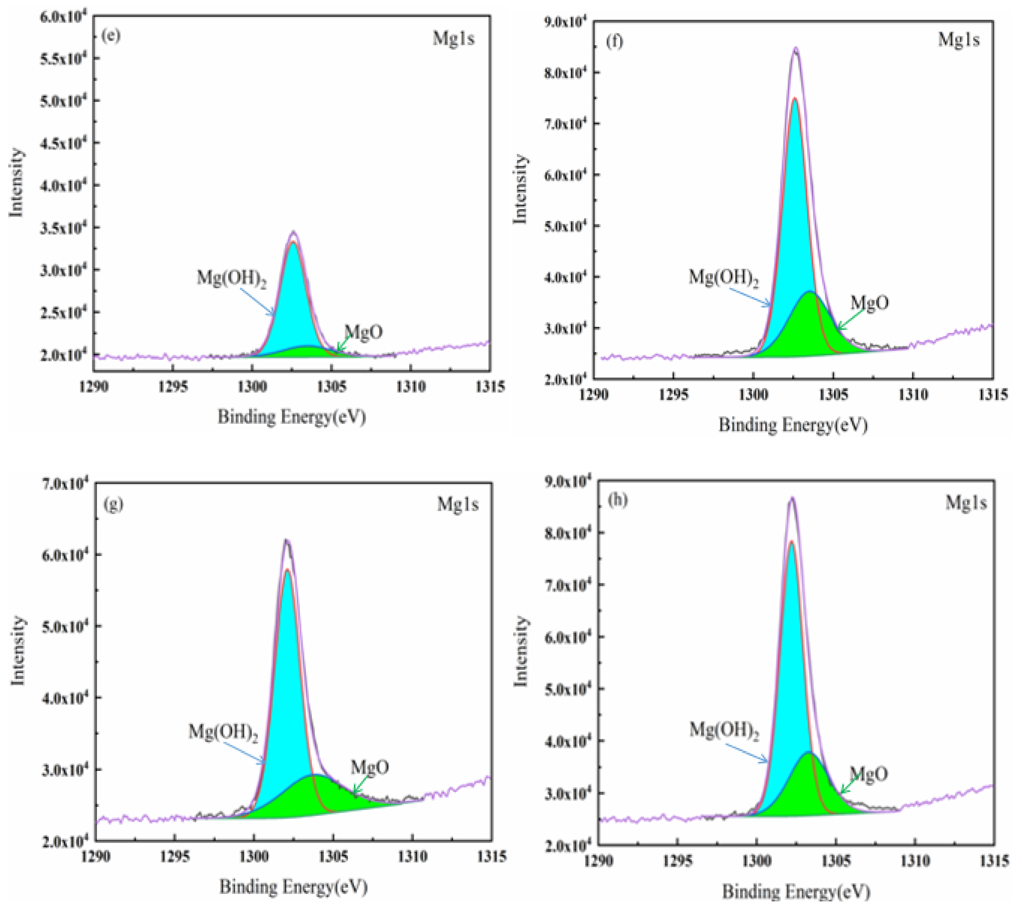
3.3. Surface Analysis

In order to further analyze the corrosion behavior of the Mg-x Sn alloys, after the samples were immersed in the 3.5 wt.% NaCl solution for 1 h at 25 °C, followed by XPS detection. The results are shown in Figure 5. The Sn3d spectrum shows Sn3d3/2 (binding energy ≈ 495.37 eV), which is typically corresponding to SnO2 [29]. As for Mg 1s, it is divided into two peaks, one corresponds to Mg(OH)2 with a binding energy of about 1302.70 eV; the other is MgO with a binding energy of about 1303.90 eV. The content of Sn has a significant effect on the intensity and area of the SnO2 peaks. Among them, the content of SnO2 in the Mg-2.5Sn alloy reaches the maximum value. SnO2 is more stable than MgO and Mg(OH)2 in neutral salt solution, and is dense and insoluble in water. Thus, SnO2 is beneficial to improve the compactness and corrosion resistance of thin films [23]. The SnO2 film on the surface can resist the penetration of corrosion ions into the Mg matrix, weaken the pitting corrosion caused by the Mg2Sn phase, and reduce the corrosion rate. Therefore, this is the main reason why Mg-2.5Sn has the best corrosion resistance.

3.4. Electrochemical Impedance Spectra

Figure 6a presents the EIS Nyquist plots for Mg-x Sn. Figure 6b shows the Bode plot in terms of the modulus value of impedance vs. frequency. According to general theory, the higher the modulus of an alloy, the higher its corrosion resistance. Mg-2.5Sn has the highest modulus, showing a high corrosion resistance, which is consistent with Icorr in Table 2. The equivalent circuit was fitted to further quantitatively elucidate the corrosion mechanism of the Mg-x Sn alloys. The equivalent circuits fitted to the EIS results are shown in Figure 6c. All four alloys have one high frequency capacitive loop, two mid-frequency capacitive loops and one inductive loop. Rs is the solution resistance. Rct is a charge transfer resistance, and it forms a high-frequency capacitor circuit with capacitor C1. The capacitor circuit at high frequency is caused by the charge transfer resistance, and the diameter of the capacitor circuit related to Rct determines the size of the impedance and corrosion resistance. Generally, the mid-frequency capacitance loop is related to the accumulation of corrosion products and the surface film on the sample surface. A double-layer capacitance CPEdl is associated with the mid-frequency capacitive loop. The dispersion coefficient n of CPEdl represents how smooth the electrical double layer is, which varies from 0 to1. The inhomogeneity of the surface due to the accumulation of corrosion products causes dispersion effects, and this capacitive behavior is represented by CPEdl instead of an ideal capacitor. C2 and R2 also form an intermediate frequency capacitor circuit, which is related to the corrosion product film formed on the surface. RL and L describe the induced behavior at low frequencies, indicating the appearance of pitting or cracking of the film.
Table 3 presents the electrochemical parameters after equivalent circuit fitting. The charge transfer resistors are listed in their descending order:
Mg-2.5Sn (1233 Ω·cm2) > Mg-4Sn (867.6 Ω·cm2) > Mg-1Sn (457.3 Ω·cm2) > Mg-0.5Sn (334.6 Ω·cm2), the reduction of the capacitance loop radius and the reduction of the charge transfer resistance means that the self-corrosion rate is accelerated [30]. This result is in good agreement with the fitting of the polarization curve and the results obtained by the weight loss method. Table 4 summarizes the electrochemical performance of several Mg-Sn-based anode materials. Corrosion resistance of Mg-Sn-based alloys changes significantly with increasing Sn content. In this work, Mg-2.5Sn has the highest corrosion resistance and Mg-0.5Sn has the worst corrosion resistance.

3.5. Discharge Behavior

Figure 7 presents the discharge curves for the Mg-x Sn alloys in 3.5 wt.% NaCl solution for 10 h at different applied current densities. Table 5 exhibits average discharge potential of the Mg-air batteries discharged for 10 h. In contrast, the discharge voltage of Mg-2.5Sn anode is more stable, and the average discharge voltage can reach up to 1.461 V. When the Sn content is ≤1%, the content of the Mg2Sn phase is small, and its uniform distribution cannot be guaranteed during the casting process. The grain size of the matrix is different, and there are many coarse grains. Therefore, the dissolution rates of the magnesium matrix differ in the discharge process, which will lead to severe corrosion in local areas and the formation of a large number of corrosion products, and the discharge products formed by coarse grains are more difficult to self-stripping [14]. It means that the discharge product Mg(OH)2 of Mg-0.5Sn and Mg-1Sn accumulates faster than Mg-2.5Sn and Mg-4Sn when the current density is ≤5 mA cm−2, resulting in lower operating voltage. In addition, with the increase of Sn content, the volume fraction of Mg2Sn phase increases, which can improve its discharge activity by promoting the self-exfoliation of discharge products, however, this phenomenon is particularly pronounced at small current densities. Figure 8 shows the surface of macroscopic products formed after Mg-x Sn anode was discharged at different current densities for 10 h. When the current density is ≤5 mA cm−2 and Sn ≥ 2.5%, Figure 8c1–c3,d1,d2 can be seen, after 10 h of discharge, the discharge products are not completely covered on the anode. On the surface, there are still active areas that can participate in the discharge, and the formation and exfoliation of discharge products can achieve a dynamic balance at this time.
The cast Mg-2.5Sn and Mg-4Sn anodes have dense saw tooth voltage fluctuations starting from a current density of 20 mA cm−2, and the fluctuation range increases with the applied current density. With the increase of current density, the formation rate of discharge products is also accelerated, which has offset the effect of Mg2Sn phase on improving the discharge activity of the alloy. Moreover, the average discharge voltages of all alloys showed a downward trend, which may be due to the fact that insoluble SnO2 closed the porous Mg(OH)2 to a certain extent, making Mg(OH)2 accumulate on the surface of the matrix, resulting in a decrease in battery voltage. The average discharge voltages of Mg-0.5Sn and Mg-1Sn show a gentle downward trend with increasing current density. The drop of Mg-2.5Sn and Mg-4Sn fluctuates greatly.
The performance of Mg-x Sn anode in a magnesium–air battery under different current densities is shown in Figure 9. Discharge capacity, anode efficiency and specific energy are important criteria to evaluate the discharge performance of magnesium anode. According to the average weight loss before and after discharge, the discharge capacity (C) and anode utilization efficiency can be calculated (η). The specific energy is related to discharge capacity and average discharge voltage.
For all anodes, Mg-1Sn exhibits the highest discharge capacity and anode efficiency among the four anode materials, which are 1245.72 mAh·g−1 and 56.11%, respectively. Figure 9b (right) shows the specific energy of the four anodes, presenting the energy output capability. The specific energy of Mg-0.5Sn reaches a peak value of 1258.78 mWh·g−1 when the current density is 40 mA cm−2.

3.6. Anode Surface Analysis after Battery Discharging

In order to further understand the discharge behavior of the Mg-x Sn anode, the discharge products after 10 h anode discharge were removed, and then the discharge morphology was analyzed, as shown in Figure 10. At a current density of 1 mA cm−2, the surface of Mg-0.5Sn is mostly relatively flat, but locally shows deep pits and a step-like layered structure, that is, there is severe local dissolution, which may be caused by the crystal orientation of [31,32]. There were many grooves with the same shapes in the cast Mg-2.5Sn anode, and the smooth surface is conducive to the exfoliation of discharge products. Mg-0.5Sn and Mg-1Sn have no obvious cracks on the surface after discharge. On the contrary, cracks are formed on the surface of Mg-2.5Sn and Mg-4Sn, which the red arrows in Figure 10g,j refer to. As the Sn content increases, the second phase increases, and the Mg2Sn secondary phase and the segregation of Sn along the dendritic region lead to a faster dissolution rate than the Mg matrix, resulting in the separation of intermetallic compounds and the formation of deep cracks at the grain boundaries. The formation of cracks helps to form a larger active area, and the electrolyte also penetrates easily, thereby improving the discharge activity.
It can be seen from Figure 10c,f,i,l that when the current density increases to 40 mA cm−2, the depth and density of pits formed after discharge increase significantly. Uniform and flat pits are formed on the surface of the Mg-1Sn anode, which helps to improve the discharge performance. Mg-0.5Sn and Mg-2.5Sn showed larger deep pits and voids on the surface after discharge, while Mg-4Sn showed more high convex structures. In aqueous magnesium batteries, the bulk effect is unavoidable, especially at small current densities [2]. The formation of the bulk effect is closely related to the applied current density and the microstructure of the magnesium anode [31]. As the current density increases, the dissolution rate of the anode gradually increases, which can weaken the influence of the bulk effect; however, at a current density of 40 mA cm−2, there are still many uneven areas on the surface of Mg-0.5Sn, Mg-2.5Sn and Mg-4Sn, and wasteful dissolution, which reduces the discharge performance.

4. Conclusions

The electrochemical behavior of the Mg-x Sn alloys was investigated by a weight loss method and electrochemical measurements. The results show that Mg-2.5Sn has the best corrosion resistance. The SnO2 film on the surface has a protective effect, which can effectively inhibit the expansion of pitting corrosion, and improve the corrosion resistance. In addition, an appropriate amount of Mg2Sn phase can also reduce the self-corrosion rate.
At low current density, the presence of an appropriate amount of Mg2Sn phase can promote the dynamic balance between the formation and exfoliation of the discharge products, and conversely, the influence of galvanic corrosion and bulk effect is aggravated. Compared with other alloys, the average discharge voltages of Mg-0.5Sn and Mg-1Sn decreased steadily with increasing current density. Mg-1Sn exhibits the highest anode efficiency and discharge capacity of 56.11% and 1245.72 mAh g−1, respectively. The maximum average discharge voltage of Mg-2.5Sn is 1.461 V.

Author Contributions

C.G.: Writing—original draft, Writing—review & editing, Methodology. T.W.: Formal analysis, Funding acquisition, Project administration. W.H.: Methodology, Resources. Q.L.: Methodology, Funding acquisition, Project administration. Y.Z.: Resources, Project administration. Q.Z.: Formal analysis, Supervision. T.L.: Formal analysis, Supervision. All authors have read and agreed to the published version of the manuscript.

Funding

This research was financially supported by National Natural Science Foundation of China (Grant No. 51974082), and National Natural Science Foundation of China (Grant No. 51901037), and the 111 Project 2.0 of China, (No. BP0719037).

Data Availability Statement

Not applicable.

Conflicts of Interest

The authors declare no conflict of interest.

References

  1. Chen, X.; Liu, X.; Le, Q.; Zhang, M.; Liu, M.; Atrens, A. A comprehensive review of the development of the magnesium anode for primary batteries. J. Mater. Chem. A 2021, 9, 12367–12399. [Google Scholar] [CrossRef]
  2. Deng, M.; Wang, L.; Vaghefinazari, B.; Xu, W.; Feiler, C.; Lamaka, S.V.; Höche, D.; Zheludkevich, M.L.; Snihirova, D. High-energy and durable aqueous magnesium batteries: Recent advances and perspectives. Energy Storage Mater. 2021, 43, 238–247. [Google Scholar] [CrossRef]
  3. Cheng, F.; Chen, J. Metal–air batteries: From oxygen reduction electrochemistry to cathode catalysts. Cheminform 2012, 41, 2172–2192. [Google Scholar] [CrossRef] [PubMed]
  4. Xuan, L.; Liu, S.; Xue, J. Discharge performance of the magnesium anodes with different phase constitutions for Mg-air batteries. J. Power Source 2018, 396, 667–674. [Google Scholar]
  5. Chen, X.; Zou, Q.; Le, Q.; Zhang, M.; Liu, M.; Atrens, A. Influence of heat treatment on the discharge performance of Mg-Al and Mg-Zn alloys as anodes for the Mg-air battery. Chem. Eng. J. 2021, 433, 133797. [Google Scholar] [CrossRef]
  6. Yang, Y.; Xiong, X.; Chen, J.; Peng, X.; Chen, D.; Pan, F. Research advances in magnesium and magnesium alloys worldwide in 2020. J. Magnes. Alloys 2021, 9, 705–747. [Google Scholar] [CrossRef]
  7. Gu, X.-J.; Cheng, W.-L.; Cheng, S.-M.; Liu, Y.-H.; Wang, Z.-F.; Yu, H.; Cui, Z.-Q.; Wang, L.-F.; Wang, H.-X. Tailoring the microstructure and improving the discharge properties of dilute Mg-Sn-Mn-Ca alloy as anode for Mg-air battery through homogenization prior to extrusion. J. Mater. Sci. Technol. 2020, 60, 77–89. [Google Scholar] [CrossRef]
  8. Chen, X.; Zou, Q.; Le, Q.; Hou, J.; Guo, R.; Wang, H.; Hu, C.; Bao, L.; Wang, T.; Zhao, D.; et al. The quasicrystal of Mg–Zn–Y on discharge and electrochemical behaviors as the anode for Mg-air battery. J. Power Source 2020, 451, 227807. [Google Scholar] [CrossRef]
  9. Zou, Q.; Le, Q.; Chen, X.; Jia, Y.; Ban, C.; Wang, T.; Wang, H.; Guo, R.; Ren, L.; Atrens, A. The influence of Ga alloying on Mg-Al-Zn alloys as anode material for Mg-air primary batteries. Electrochim. Acta 2021, 401, 139372. [Google Scholar] [CrossRef]
  10. Deng, M.; Wang, L.; Höche, D.; Lamaka, S.V.; Jiang, P.; Snihirova, D.; Scharnagl, N.; Zheludkevich, M.L. Corrigendum to “Ca/In micro alloying as a novel strategy to simultaneously enhance power and energy density of primary Mg-air batteries from anode aspect”. J. Power Source 2020, 472, 228528. [Google Scholar] [CrossRef]
  11. Chen, Y.; Cheng, W.; Gu, X.; Yu, H.; Wang, H.; Niu, X.; Wang, L.; Li, H. Discharge performance of extruded Mg-Bi binary alloys as anodes for primary Mg-air batteries. J. Alloys Compd. 2021, 886, 161271. [Google Scholar] [CrossRef]
  12. Deng, M.; Hoeche, D.; Lamaka, S.V.; Snihirova, D.; Zheludkevich, M.L. Mg-Ca binary alloys as anodes for primary Mg-air batteries. J. Power Source 2018, 396, 109–118. [Google Scholar] [CrossRef]
  13. Tong, F.; Chen, X.; Wang, Q.; Wei, S.; Gao, W. Hypoeutectic Mg–Zn binary alloys as anode materials for magnesium-air batteries. J. Alloys Compd. 2020, 857, 157579. [Google Scholar] [CrossRef]
  14. Xiong, H.; Yu, K.; Yin, X.; Dai, Y.; Yan, Y.; Zhu, H. Effects of microstructure on the electrochemical discharge behavior of Mg-6wt%Al-1wt%Sn alloy as anode for Mg-air primary battery. J. Alloys Compd. 2016, 708, 652–661. [Google Scholar] [CrossRef]
  15. Gu, X.J.; Cheng, W.L.; Cheng, S.M.; Yu, H.; Wang, Z.F.; Wang, H.X.; Wang, L.F. Discharge Behavior of Mg–Sn–Zn–Ag Alloys with Different Sn Contents as Anodes for Mg-air Batteries. J. Electrochem. Soc. 2020, 167, 020501. [Google Scholar] [CrossRef]
  16. Liu, H.; Yan, Y.; Wu, X.; Fang, H.; Chu, X.; Huang, J.; Zhang, J.; Song, J.; Yu, K. Effects of Al and Sn on microstructure, corrosion behavior and electrochemical performance of Mg–Al-based anodes for magnesium-air batteries. J. Alloys Compd. 2020, 859, 157755. [Google Scholar] [CrossRef]
  17. Liu, X.; Shan, D.; Song, Y.; Chen, R.; Han, E. Influences of the quantity of Mg2Sn phase on the corrosion behavior of Mg–7Sn magnesium alloy. Electrochim. Acta 2011, 56, 2582–2590. [Google Scholar] [CrossRef]
  18. Ha, H.Y.; Kang, J.Y.; Kim, S.G.; Kim, B.; Park, S.S.; Yim, C.D.; You, B.S. Influences of metallurgical factors on the corrosion behaviour of extruded binary Mg–Sn alloys. Corros. Sci. 2014, 82, 369–379. [Google Scholar] [CrossRef]
  19. Tong, F.; Chen, X.; Teoh, T.E.; Wei, S.; Waterhouse, G.I.N.; Gao, W. Mg–Sn Alloys as Anodes for Magnesium-Air Batteries. J. Electrochem. Soc. 2021, 168, 110531. [Google Scholar] [CrossRef]
  20. Han, L.; Zhang, Y.; Guo, Y.; Wan, Y.; Fan, L.; Zhou, M.; Quan, G. Electrochemical behaviors and discharge performance of Mg-Sn binary alloys as anodes for Mg-air batteries. Mater. Res. Express 2021, 8, 126531. [Google Scholar] [CrossRef]
  21. Yu, Z.; Huang, Q.; Zhang, W.; Luo, C.; Guan, H.; Chen, Y.; Song, H.; Hu, Z.; Luc, C. Effect of Sn content on the mechanical properties and corrosion behavior of Mg-3Al-xSn alloys. Mater. Res. Express 2020, 7, 076505. [Google Scholar] [CrossRef]
  22. Song, G.L. Effect of tin modification on corrosion of AM70 magnesium alloy. Corros. Sci. 2009, 51, 2063–2070. [Google Scholar] [CrossRef]
  23. Yang, J.; Yim, C.D.; You, B.S. Characteristics of Surface Films Formed on Mg–Sn Alloys in NaCl Solution. J. Electrochem. Soc. 2016, 163, C395–C401. [Google Scholar] [CrossRef]
  24. Jiang, W.; Wang, J.; Zhao, W.; Liu, Q.; Jiang, D.; Guo, S. Effect of Sn addition on the mechanical properties and bio-corrosion behavior of cytocompatible Mg–4Zn based alloys. J. Magnes. Alloys 2019, 7, 15–26. [Google Scholar] [CrossRef]
  25. Wang, J.; Yang, L.; Song, H.; Zhou, X. Study of the corrosion behavior and the corrosion films formed on the surfaces of Mg–xSn alloys in 3.5 wt.% NaCl solution. Appl. Surf. Sci. 2014, 317, 1143–1150. [Google Scholar] [CrossRef]
  26. Yu, K.; Xiong, H.Q.; Wen, L.; Dai, Y.-L.; Yang, S.-H.; Fan, S.-F.; Teng, F.; Qiao, X.-Y. Discharge behavior and electrochemical properties of Mg–Al–Sn alloy anode for seawater activated battery. Trans. Nonferrous Met. Soc. China 2015, 25, 1234–1240. [Google Scholar] [CrossRef]
  27. Chen, X.; Jia, Y.; Le, Q.; Wang, H.; Zhou, X.; Yu, F.; Atrens, A. Discharge properties and electrochemical behaviors of AZ80-La-Gd magnesium anode for Mg-air battery. J. Magnes. Alloys 2020, 9, 2113–2121. [Google Scholar] [CrossRef]
  28. Wang, N.; Wang, R.; Peng, C.; Feng, Y.; Chen, B. Effect of hot rolling and subsequent annealing on electrochemical discharge behavior of AP65 magnesium alloy as anode for seawater activated battery. Corros. Sci. 2012, 64, 17–27. [Google Scholar] [CrossRef]
  29. Cheng, W.; Chen, Y.; Gu, X.; Feng, J.; Yu, H.; Wang, H.; Niu, X.; Wang, L.; Li, H. Revealing the influence of crystallographic orientation on the electrochemical and discharge behaviors of extruded diluted Mg–Sn–Zn–Ca alloy as anode for Mg-air battery. J. Power Source 2021, 520, 230802. [Google Scholar] [CrossRef]
  30. Chen, X.; Liao, Q.; Le, Q.; Zou, Q.; Wang, H.; Atrens, A. The influence of samarium (Sm) on the discharge and electrochemical behaviors of the magnesium alloy AZ80 as an anode for the Mg-air battery. Electrochim. Acta 2020, 348, 136315. [Google Scholar] [CrossRef]
  31. Deng, M.; Wang, L.; Hoeche, D.; Lamaka, S.V.; Snihirova, D.; Vaghefinazari, B.; Zheludkevich, M.L. Clarifying the decisive factors for utilization efficiency of Mg anodes for primary aqueous batteries. J. Power Source 2019, 441, 227201. [Google Scholar] [CrossRef]
  32. Song, G.L.; Xu, Z. Crystal orientation and electrochemical corrosion of polycrystalline Mg. Corros. Sci. 2012, 63, 100–112. [Google Scholar] [CrossRef]
Figure 1. Optical microscopy metallographs of as-cast: (a) Mg-0.5Sn, (b) Mg-1Sn, (c) Mg-2.5Sn, (d) Mg-4Sn and (e) statistic of average grain size.
Crystals 12 01053 g001
Figure 2. XRD patterns of the investigated alloys: (a) Mg-0.5Sn, (b) Mg-1Sn, (c) Mg-2.5Sn and (d) Mg-4Sn.
Crystals 12 01053 g002
Figure 3. SEM images of (a) Mg-2.5Sn, (c) Mg-4Sn and (b,d) the marked region of Mg-4Sn; and EDS images of (e,i) Mg-2.5Sn; (g,k) Mg-4Sn; (f) EDS from spot A; (j) EDS from spot B; (h) EDS from spot C; and (l) EDS from spot D.
Crystals 12 01053 g003
Figure 4. (a) Polarization curves in 3.5 wt.% NaCl solution of the Mg-x Sn. (b) Weight loss rates of the Mg-x Sn alloys after immersion in a 3.5% NaCl solution for 110 h.
Crystals 12 01053 g004
Figure 5. XPS surface analysis results of Mg-x Sn: (a,e) Mg-0.5Sn; (b,f) Mg-1Sn; (c,g) Mg-2.5Sn; and (d,h) Mg-4Sn.
Crystals 12 01053 g005aCrystals 12 01053 g005b
Figure 6. (a) EIS Nyquist plots for Mg−x Sn; (b) Bode plots of impedance modulus vs. frequency; and (c) equivalent circuits used for fitting the EIS spectra.
Crystals 12 01053 g006
Figure 7. Discharge curves of the Mg−x Sn alloys anodes in 3.5 wt.% NaCl solution for 10 h at a current density of: (a) 1 mA cm −2, (b) 2 mA cm−2, (c) 5 mA cm−2, (d) 10 mA cm−2, (e) 20 mA cm−2, (f) 40 mA cm−2 and (g) 80 mA cm−2.
Crystals 12 01053 g007aCrystals 12 01053 g007b
Figure 8. Macroscopic surfaces of the four studied anodes after 10 h of discharge at different current densities in 3.5 wt.% NaCl solution: (a1a7) Mg-0.5Sn, (b1b7) Mg-1Sn, (c1c7) Mg-2.5Sn, and (d1d7) Mg-4Sn.
Crystals 12 01053 g008
Figure 9. The discharge performance of Mg-x Sn anode in magnesium–air battery under different current densities: (a) anodic efficiency, and (b) discharge capacity and specific energy.
Crystals 12 01053 g009
Figure 10. The surface morphologies of (a,b) Mg-0.5Sn, (d,e) Mg-1Sn, (g,h) Mg-2.5Sn and (j,k) Mg-4Sn anodes after 10 h of discharge at 1 mA cm−2 without the discharge products; surface morphologies of (c) Mg-0.5Sn, (f) Mg-1Sn, (i) Mg-2.5Sn, and (l) Mg-4Sn anodes after 10 h of discharge at 40 mA cm−2 without the discharge products.
Crystals 12 01053 g010
Table 1. Chemical compositions of experimental alloy (wt.%).
AlloySn
Mg-0.5Sn0.46
Mg-1Sn0.94
Mg-2.5Sn2.47
Mg-4Sn3.87
Table 2. Fitting results of polarization curves.
AlloyEcorr (vs. SCE)/VJcorr/(μA·cm−2)
Mg-0.5Sn−1.45215.187
Mg-1Sn−1.53310.131
Mg-2.5Sn−1.5066.315
Mg-4Sn−1.4719.463
Table 3. Electrochemical parameters of the fitted equivalent circuits.
AlloyRSC1RctCPEdlR1C2R2LRL
Ω·cm2μF·cm−2Ω·cm2Y0 × 10−5Ω−1 cm2 SnnΩ·cm2μF·cm−2Ω·cm2HΩ·cm2
Mg-0.5Sn4.5090.295334.60.7180.9667.7905.84466.941294121.1
Mg-1Sn4.4362.513457.31.1520.9090.7713.27258.381753164.2
Mg-2.5Sn4.8350.64312331.7070.9171.070321.72928108,0002465
Mg-4Sn4.9040.395867.61.8660.9154.222204.952794449537.9
Table 4. Literature survey of electrochemical performance of several Mg-Sn-based anode materials.
AlloyFabricationSolutionCorrosion Resistance (from High to Low)Ref.
Mg-x Sn (x = 0.5, 1.0, 2.5 wt.% and 4.0 wt.%)Casting3.5 wt.% NaClMg-2.5Sn > Mg-4Sn > Mg-1Sn > Mg-0.5SnThis work
recast Mg, Mg-x Sn (x = 1.0, 3.0, 5.0 wt.%)Casting3.5 wt.% NaClMg-5Sn > Mg-3Sn > recast Mg > Mg-1Sn[19]
Mg-x Sn (x = 1.0, 5.0, 9.0 wt.%)Casting3.5 wt.% NaClMg-1Sn > Mg-5Sn > Mg-9Sn[20]
Mg-3Al-xSn (x = 0, 1.0, 1.5, 2.0 wt.%)Homogenization + hot extrusion3.5 wt.% NaClMg-3Al-1Sn > Mg-3Al > Mg-3Al-1.5Sn > Mg-3Al-2Sn[21]
AM70, AT72Casting5 wt.% NaClAM70 > AT72[22]
Mg-x Sn (x = 2.0, 5.0 wt.%)Solution-heat-treated + water cooled0.6 M NaClMg-5Sn > Mg-2Sn > Mg[23]
Mg-4Zn-x Sn (x = 0, 1.0, 1.5, 2.0 wt.%)Saltwater quenching + extrusionPBS (37 ± 0.5 °C)Mg–4Zn–1.5Sn > Mg–4Zn–1.0Sn > Mg–4Zn–2.0Sn > Mg–4Zn[24]
Mg-x Sn (x = 0.5, 1.0, 1.5, and 2.0 wt.%)Casting3.5 wt.% NaClMg-1.5Sn > Mg-2.0Sn > Mg-0.5Sn > Mg-1.0Sn[25]
Mg-6Al-xSn (x = 1.0, 5.0 wt.%)Homogenization + hot-rollingArtificial sea waterMg-6Al-5Sn > Mg-6Al-1Sn[26]
Table 5. Average discharge voltage of the studied anode at different current densities.
Current Densities/mA cm−2Average Discharge/V
Mg-0.5SnMg-1SnMg-2.5SnMg-4Sn
11.4221.3941.4611.437
21.3911.3781.4031.379
51.3841.3481.3651.303
101.3331.2931.2981.192
201.2171.1721.0761.05
401.0861.0230.9940.878
800.8150.9630.7930.765
Publisher’s Note: MDPI stays neutral with regard to jurisdictional claims in published maps and institutional affiliations.

