Article

Intergranular Cracking in Mg-Gd-Y Alloy during Tension Test

1
School of Mechanical and Electronic Engineering, Shandong Jianzhu University, Jinan 250101, China
2
Research Center of High Performance Materials Forming, Shandong Jianzhu University, Jinan 250101, China
*
Author to whom correspondence should be addressed.
Crystals 2022, 12(8), 1040; https://doi.org/10.3390/cryst12081040
Submission received: 10 July 2022 / Revised: 20 July 2022 / Accepted: 25 July 2022 / Published: 27 July 2022
(This article belongs to the Special Issue Applications of Crystal Plasticity in Forming Technologies)

Abstract

:
The intergranular cracking in the Mg-Gd-Y alloy was investigated by an in situ tension test combined with an electron backscattered diffraction (EBSD) measurement and digital image correlation (DIC). During the tension test, the crack was found at the triangle point of the grain boundary area with profuse slip traces. DIC results show that inhomogeneous strain distribution can be found at the triangle point area, leads to serious deformation incompatibility at this point. This also leads to a weak point for crack initiation, and as tension strain increases, the crack would extend from the weak point along the grain boundary.

1. Introduction

The elongation of wrought magnesium at ambient temperature can achieve 20% or even more, which is larger than that of traditional aluminum alloys [1,2,3,4]. However, the formability of wrought magnesium still cannot be compared with aluminum alloys at ambient temperature, which impedes the development of wrought magnesium.
It is common to think that damage nucleation during the deformation process occurs at locations with large strain concentrations, where substantial heterogeneous deformation occurs. If large local strains are effective in accommodating the required geometry changes, they may prevent damage nucleation, whereas it is conceivable that damage may nucleate where insufficient strain or shape accommodation occurs. Such variability in shape accommodation is connected to crystal orientations and crystallographic deformation mechanisms. In previous studies, cracking was thought to be related to {10–12} tension twinning [5], {10–11}–{10–12} double twinning [6,7], persistent slip bands [8] or grain boundaries [9]. J. Koike et al. [7] thought {10–11}–{10–12} double twinning would lead to the formation of large surface steps, cracks and final failure. An Luo et al. [10] thought that fatigue cracks mainly exist as transgranular cracks, and the crack propagation path is related to the orientation of target grains and the loading direction. Small cracks usually initiate on basal planes in grains with a larger Schmid factor.
This paper focused on the microstructure evolution and fracture behavior in the Mg-Gd-Y alloy, which is critical to its ductility. In situ tension tests were used in combination with electron backscattered diffraction (EBSD) and digital image correlation (DIC) to correlate the activation of deformation modes and fracture behavior. Strain accommodation in the grain boundary area was carefully analyzed, and the effects of grain orientation and grain boundary compatibility were discussed.

2. Experimental Procedure

The alloy used had a chemical composition of Mg-8.0Gd-3.0Y (wt%) (GW83). It was prepared by extrusion at 450 °C with an extrusion ratio of 25:1.
The in situ tensile test was performed using a micro-test system provided by Deben UK Ltd, Suffolk UK. with a load cell of 5 KN capacity, installed inside an FEI Quanta 250 FEG SEM. Before tensile tests, the sample surfaces were mechanically polished using a sequence of ethanol-based diamond suspensions of 6, 3 and 1 μm. This was followed by fine-polishing using a colloidal silica suspension (OPS), and a final 2–4 s etching using a solution of 5% HNO3, 15% acetic acid, 20% H2O and 60% ethanol before SEM and EBSD observations. The microstructure and grain orientation analysis was performed via EBSD (TSLTM OIM) measurements. Micro grids, illustrated in this study that had a 1 μm step size and 20 μm width were deposited on polished surfaces of the tension samples by using an FEI Nova 600 I dual-beam focused ion beam miller. During the tensile test, the samples were deformed at room temperature at a displacement rate of 0.5 mm/min along the loading direction. The loading test was carried out in steps. SEM pictures from the same area of the sample surface were collected during interrupted loading with the displacement held.

3. Results and Discussion

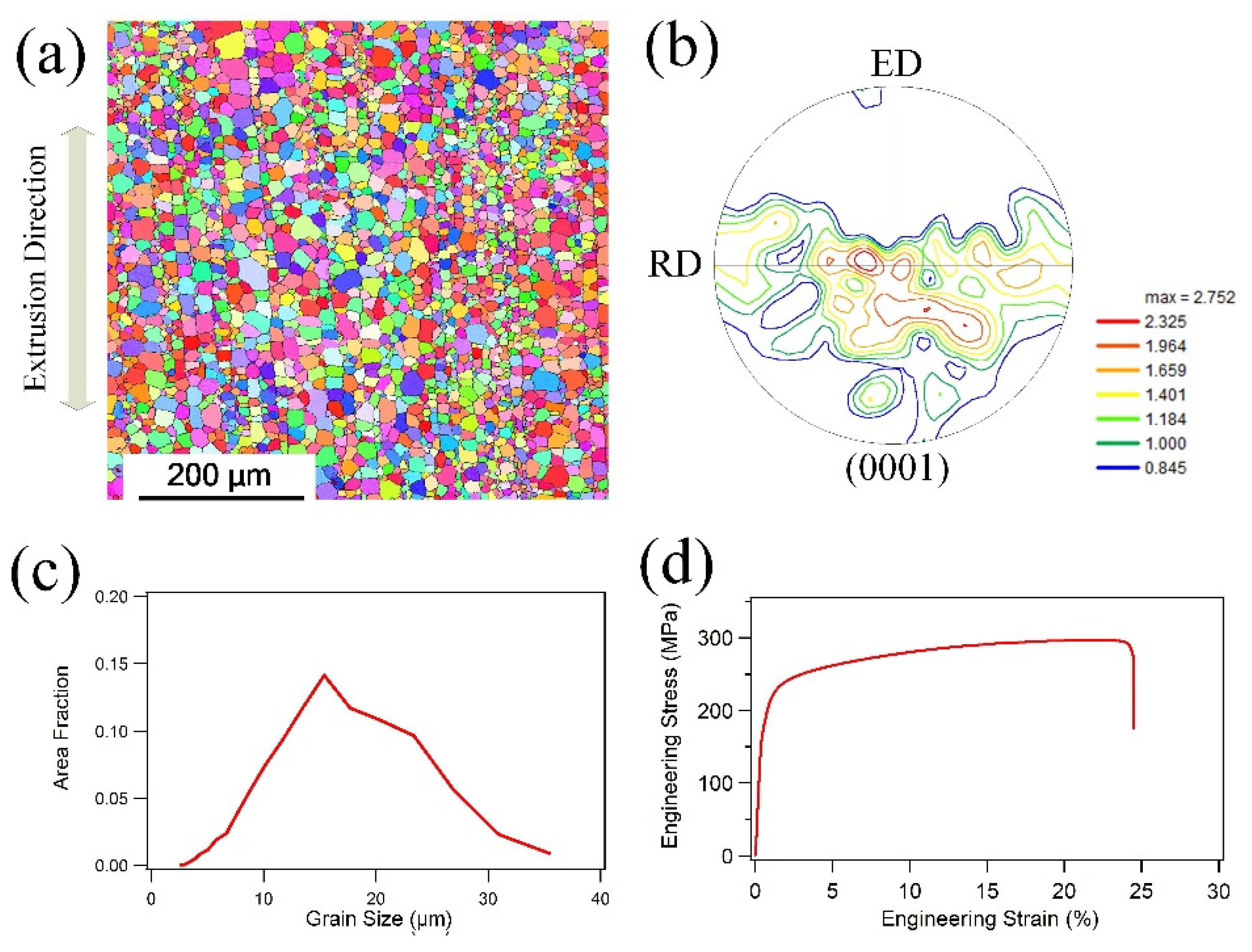
3.1. Initial Microstructure

Figure 1a shows the microstructure from the longitudinal section of the extruded bar. The specimen exhibits a full recrystallization microstructure with obvious extrusion streaks along the extrusion direction. Figure 1b shows the (0001) PF (pole figure) of the extruded tube. The texture intensity is only 2.752, which is much lower than that of an extruded AZ31 alloy. Figure 1c shows the grain size distribution of this alloy, and the average grain size is 15 μm. Figure 1d shows the stress–strain curve of this alloy. Yield strength and ultimate strengths are 180 MPa and 295 MPa, respectively. The elongation of this alloy reached 24% due to the randomized texture.

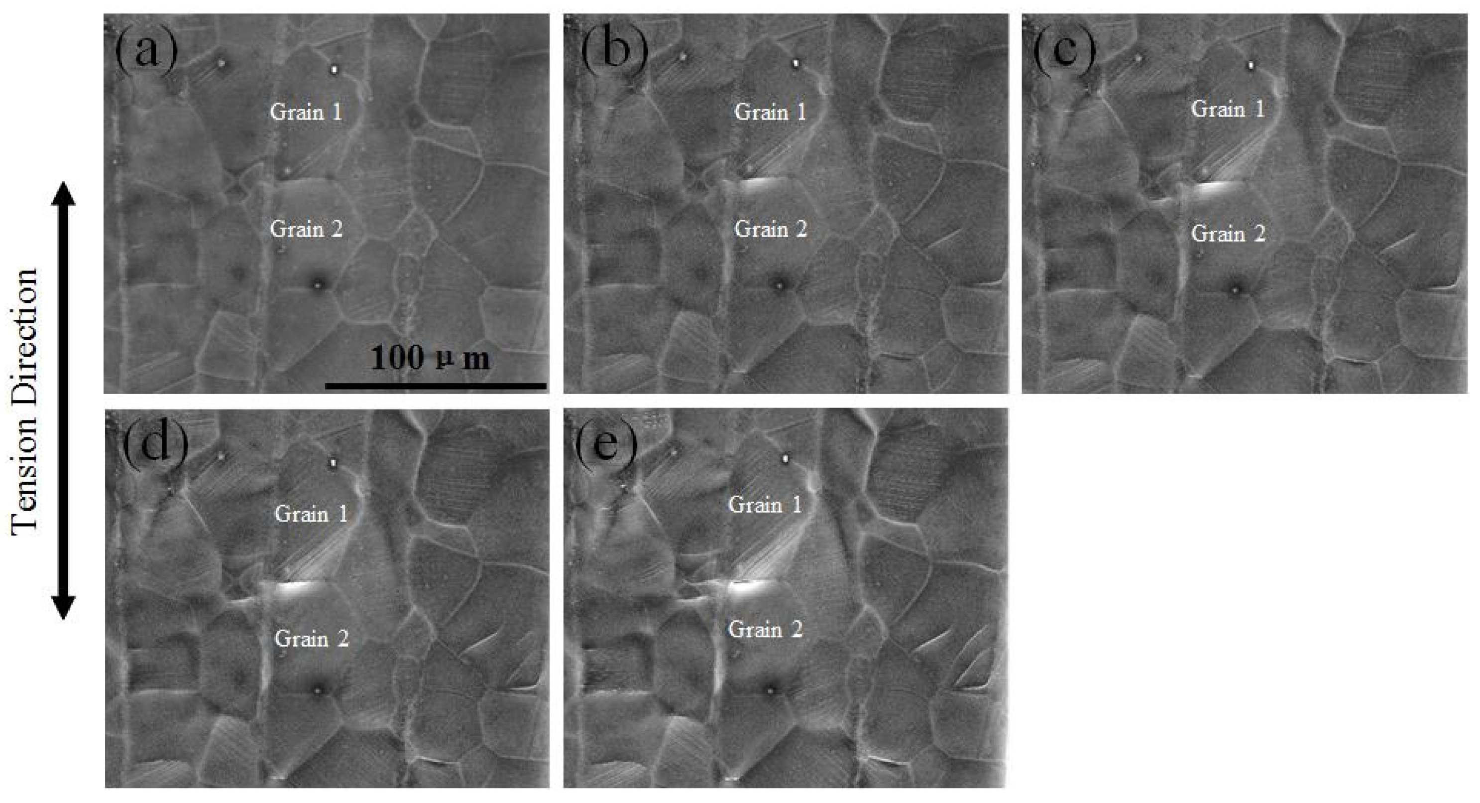
3.2. Microstructure Evolution during Tension Test

Figure 2 shows the microstructure during the in situ tension test. At the strain of 9.5% (Figure 2a), a small amount of slip trace can be observed in Grain 1. This kind of straight slip trace was thought to be a basal slip trace. However, no obvious slip trace can be found in Grain 2. At a strain of 11.5% (Figure 2b), the slip trace in Grain 1 becomes denser at the boundary close to Grain 2. As the strain increases to 12.5%, the slip trace grows much denser than before and an obvious change in the shape of the grain boundary can be found between Grain 1 and Grain 2. At the strain of 13.5%, a crack initiated at the boundary between Grain 1 and Grain 2 with an obvious slip trace in Grain 1 and negligible shape change in Grain 2. As the strain increases to 15.5%, the crack starts to propagate. Due to the in situ observation at the initiation of the grain boundary crack, it can be deduced that the slip close to the boundary and strain concentration had a significant effect on the initiation of the grain boundary crack. Moreover, noticeable fluctuation at the grain boundaries can be found as the strain increased. This indicates that strain accommodation is incompatible at the grain boundary area, which causes strain concentration during the deformation process.
In order to quantitatively analyze the effect of the slip and strain concentration of the initiation of the grain boundary crack, the grid was marked on the surface of the polished tension sample to calculate the strain distribution after deformation. Figure 3 shows the deformed microstructure during tension at the strain of 0.15. Profuse slip traces can be found in grains and transferred slip traces can be found in grain boundary areas. The red lines in Figure 3 indicate basal slip traces, which were drawn by OIM software, and the blue lines indicate prismatic slip traces. An obvious crack can be found between Grain 1 and Grain 2. Furthermore, this crack was linked to the triangle point among Grain 1, Grain 2 and Grain 3.
The strain tensor caused by the activation of a single slip (x-axis is the a-axis in the crystallography coordinates and z-axis is the c-axis in the crystallography coordinates) is assumed as:
ε = [ 0 0 1 0 0 0 1 0 0 ]
The direction of the crack is set as the y-axis and the direction perpendicular to the crack is set as the x-axis (the crack coordinate); the y-axis is approximately perpendicular to the tension direction. The strain caused by the basal slip can be calculated and the results are:
ε 1 = [ 0.7294 0.6368 0.0481 0.6368 0.5651 0.3912 0.0481 0.3912 0.1643 ]   ε 2 = [ 0.0903 0.3818 0.8464 0.3818 0.2953 0.2630 0.8464 0.2630 0.2051 ]
ε1 is the strain tensor caused by the basal slip in Grain 1 and ε2 is the strain tensor caused by the basal slip in Grain 2. εyy in Grain 1 is −0.5651 and the absolute value is much higher than that in Grain 2. The negative value indicates a compressive strain, which is induced by the activity of the basal slip. Thus, a large compressive strain is induced by the activity of the basal slip in Grain 1. The DIC analysis shown in Figure 4 confirmed the calculation above, that a large compressive strain exists at Grain 1 close to the boundary. The macro engineering strain is 0.15 and the local strain achieves −0.2 along the x-axis, which shows a huge strain concentration.

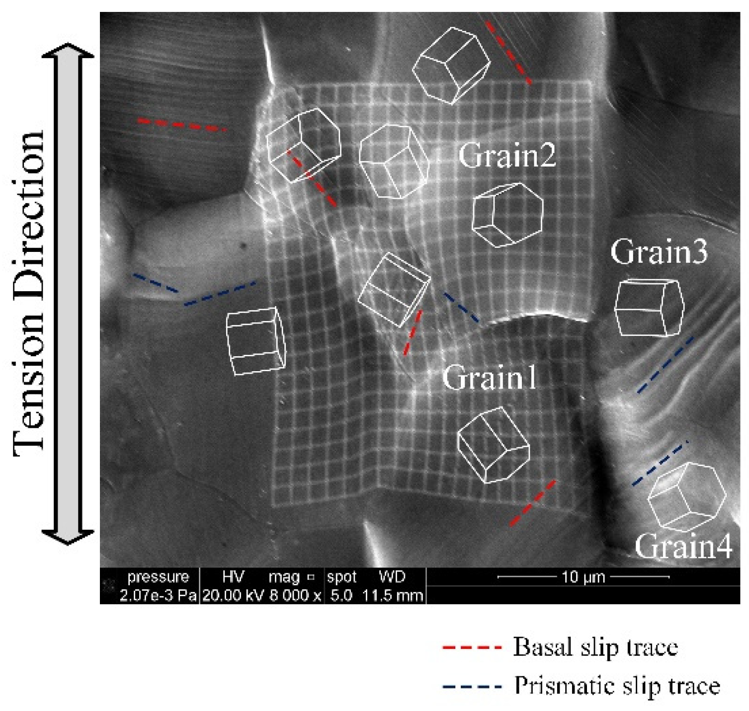
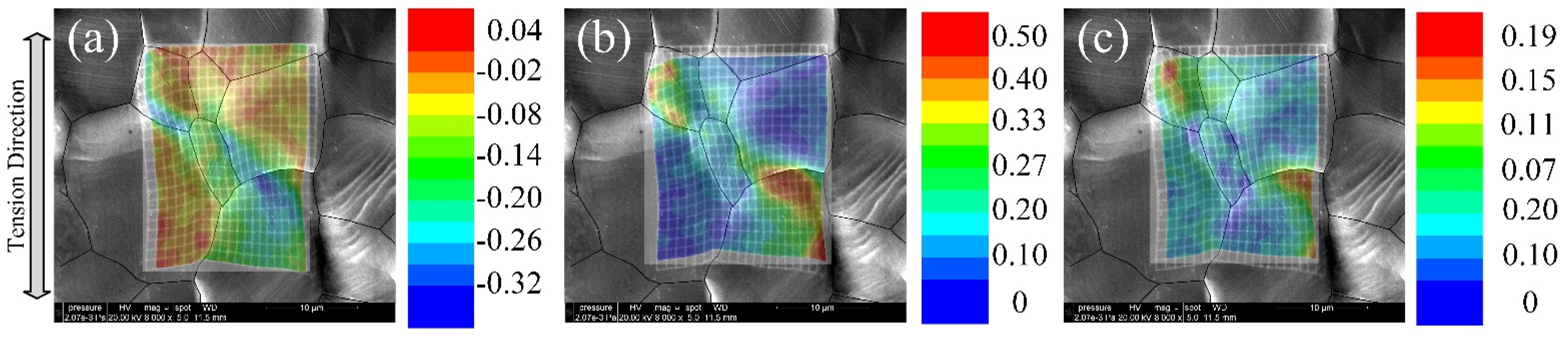
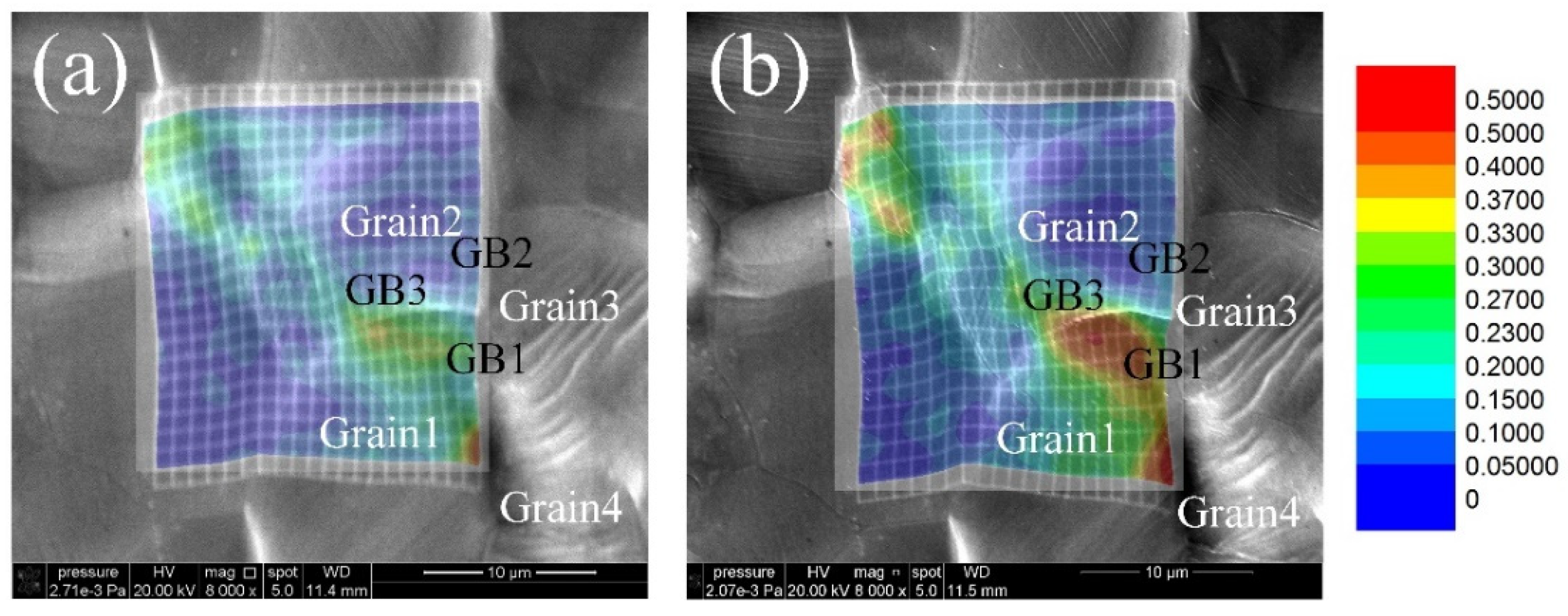
3.3. Analysis of Crack Initiation

Figure 5a,b show microstructure evolution during tension at the strain of 0.1 and 0.15 superimposed with grain maps. Strain concentration can be found at the grain boundary area between Grain 1 and Grain 2, especially at the strain of 0.15. This is because the crack extended along the grain boundary as the strain increased. Strain amplitude at the GB1 area is also high compared to that at the GB2 area. Moreover, both cracks at these two strain conditions are linked to the triangle point among Grain 1, Grain 2 and Grain 3.
It is a common thought that crack initiation is related to the activation of deformation modes in the surrounding area. Therefore, firstly, the Schmid factors of basal slip systems and prismatic systems in Grains 1–4 were calculated and shown in Table 1. The Schmid factor of the basal slip system in Grain 1 is 0.486, which is close to 0.5. Additionally, a large amount of basal slip traces can be found in Grain 1, especially in the grain boundary area near Grain 3 and Grain 4 in Figure 3. Conversely, in Grain 2, the Schmid factor of the prismatic slip system shows the highest value at 0.483. However, slip traces cannot be found obviously in Grain 2, especially at the grain boundary area near Grain 3 in Figure 3. This is because activation of the slip in the magnesium alloy needs not only its preferred grain orientation, but also needs good deformation compatibility in the adjacent grains.
In our previous study [11,12], strain accommodation at the grain boundary area was found to be related to both grain orientation and grain boundary misorientation. Grain orientation is quantified by the Schmid factor and grain boundary misorientation is quantified by deformation compatibility parameter m′ [13,14]. Therefore, the m′ values of two slip systems were calculated and shown in Table 2. Because three different prismatic slip systems own different slip planes, the activated prismatic slip system was identified as the (1–100) {11−20} slip system by slip trace analysis. This method was fully introduced in our previous paper [15]. The m′ value between the (0001) {1−210} slip system in Grain 1 and the (1–100) {11−20} slip system in Grain 3 is 0.425, which shows good deformation compatibility between these two slip systems. The Schmid factors for these two slip systems are 0.330 and 0.467, which are also high numbers. Both high values of the Schmid factor and m′ value indicated high strain amplitudes at the grain boundary area. Because the activation of basal slip systems is not favored in Grain 2 and Grain 3, and because of the relatively high CRSS of the prismatic slip, strain amplitudes are low at the grain boundary area.
It appears that the GB1 area shows high strain amplitudes and the GB2 area shows low strain amplitudes. This leads to serious deformation incompatibility at the junction point, which is a weak point for crack initiation. Thereafter, as the tension strain-increased crack extends from the weak point along GB3, it leads to intergranular cracking as seen in the results shown in Figure 5a,b. This kind of crack can also be found in the Mg-2% Gd (wt%) alloy used in a previous study [16] that used a predictive fracture initiation parameter to evaluate the probability of microcrack nucleation at the grain boundary.
There are other researchers who have studied grain boundary cracking behavior. Ashmawi and Zikry [17,18] used the slip transfer criteria to correlate dislocation density with damage based upon two assumptions: (1) damage occurs due to the dislocation accumulated and (2) the slip transfer mitigates dislocation accumulation. Because there is no reason to correlate concentrated dislocation activity with damage (concentrated dislocation activity could either mitigate or cause damage), this approach may not be effective. Ma et al. [19,20] also developed grain boundary elements that increase deformation resistance in boundaries and allow some slip transfer, but this has not been used to examine damage nucleation. There is clearly a need for an effective but simple way to identify how damage nucleates that takes into account the active slip system history in the vicinity of the boundary. In this study, intergranular cracking was found to be related to deformation incompatibility at the triangle grain boundary. If inhomogeneous strain distribution at the triangle grain boundary can be quantified, the prediction of intergranular cracking would be more accurate. Furthermore, this would provide a new perspective for preventing cracking and achieve higher ductility in magnesium alloys.

4. Conclusions

In situ tension in SEM combined with EBSD and DIC techniques was applied to investigate fracture behavior in a Mg-Gd-Y alloy. Intergranular cracking was found at the triangle grain boundary area with serious inhomogeneous strain distribution conditions. The difference in strain amplitude between linked grain boundaries along the tension direction led to severe deformation incompatibility at the triangle point, which makes it a weak point for crack initiation. As the tension strain increases, the crack extends from the weak point along the grain boundary and causes intergranular cracking.

Author Contributions

Formal analysis, J.S.; Methodology, J.S., J.L., Q.C. and L.L.; Project administration, J.S.; Writing—original draft, J.S. All authors have read and agreed to the published version of the manuscript.

Funding

This work was supported by the National Natural Science Foundation of China (Grant No. 52001188) and the Natural Science Foundation of Shandong Province (ZR2020QE161).

Conflicts of Interest

The authors declare no conflict of interest.

References

  1. Jin, L.; Mishra, R.K.; Sachdev, A.K. Texture modification during extrusion of some Mg alloys. Metall. Mater. Trans. A 2012, 43, 2148–2157. [Google Scholar] [CrossRef]
  2. Zhou, N.; Zhang, Z.; Jin, L.; Dong, J.; Chen, B.; Ding, W. Ductility improvement by twinning and twin–slip interaction in a Mg-Y alloy. Mater. Des. 2014, 56, 966–974. [Google Scholar] [CrossRef]
  3. Sandlöbes, S.; Pei, Z.; Friák, M.; Zhu, L.F.; Wang, F.; Zaefferer, S.; Raabe, D.; Neugebauer, J. Ductility improvement of Mg alloys by solid solution: Ab initio modeling, synthesis and mechanical properties. Acta Mater. 2014, 70, 92–104. [Google Scholar] [CrossRef]
  4. Luo, A.; Wu, W.; Mishra, R.; Jin, L.; Sachdev, A.; Ding, W. Microstructure and Mechanical Properties of Extruded Magnesium-Aluminum-Cerium Alloy Tubes. Metall. Mater. Trans. A 2010, 41, 2662–2674. [Google Scholar] [CrossRef]
  5. Prasad, N.S.; Kumar, N.N.; Narasimhan, R.; Suwas, S. Fracture behavior of magnesium alloys—Role of tensile twinning. Acta Mater. 2015, 94, 281–293. [Google Scholar] [CrossRef]
  6. Niknejad, S.; Esmaeili, S.; Zhou, N.Y. The role of double twinning on transgranular fracture in magnesium AZ61 in a localized stress field. Acta Mater. 2016, 102, 1–16. [Google Scholar] [CrossRef]
  7. Koike, J.; Fujiyama, N.; Ando, D.; Sutou, Y. Roles of deformation twinning and dislocation slip in the fatigue failure mechanism of AZ31 Mg alloys. Scr. Mater. 2010, 63, 747–750. [Google Scholar] [CrossRef]
  8. Wang, F.; Dong, J.; Jiang, Y.; Ding, W. Cyclic deformation and fatigue of extruded Mg–Gd–Y magnesium alloy. Mater. Sci. Eng. A 2013, 561, 403–410. [Google Scholar] [CrossRef]
  9. Tian, J.; Deng, J.-F.; Chang, Y.; Shi, Q.-X.; Liang, W.; Ma, J. A study of unstable fracture of a magnesium alloy caused by uneven microstructure. Mater. Lett. 2022, 314, 131799. [Google Scholar] [CrossRef]
  10. Luo, A.; Deng, Y.; Guan, L.; Guo, X. Role of twinning and texture on fatigue resistance enhancement of Mg-6Gd-3Y-1Nd-0.5Zr alloys. Int. J. Fatigue 2021, 153, 106471. [Google Scholar] [CrossRef]
  11. Sun, J.; Jin, L.; Dong, J.; Ding, W.; Luo, A.A. Microscopic deformation compatibility during monotonic loading in a Mg-Gd-Y alloy. Mater. Charact. 2016, 119, 195–199. [Google Scholar] [CrossRef]
  12. Sun, J.; Jin, L.; Dong, J.; Wang, F.; Dong, S.; Ding, W.; Luo, A.A. Towards high ductility in magnesium alloys—The role of intergranular deformation. Int. J. Plast. 2019, 123, 121–132. [Google Scholar] [CrossRef]
  13. Luster, J.; Morris, M.A. Compatibility of deformation in two-phase Ti-Al alloys: Dependence on microstructure and orientation relationships. Metall. Mater. Trans. A 1995, 26, 1745–1756. [Google Scholar] [CrossRef]
  14. Xin, R.L.; Liang, Y.C.; Ding, C.H.; Guo, C.F.; Wang, B.S.; Liu, Q. Geometrical compatibility factor analysis of paired extension twins in extruded Mg-3Al-1Zn alloys. Mater. Des. 2015, 86, 656–663. [Google Scholar] [CrossRef]
  15. Wang, F.; Liu, M.; Sun, J.; Feng, M.; Jin, L.; Dong, J.; Jiang, Y. Effects of initial {10–12} twins on cyclic deformation and fatigue of magnesium alloy at low strain amplitudes. Mater. Charact. 2019, 149, 118–123. [Google Scholar] [CrossRef]
  16. Liu, C.; Jin, L.; Dong, J.; Wang, F. The use of the fracture initiation parameter F1 to predict microcrack nucleation at grain boundaries in Mg-2%Gd alloy. Mater. Des. 2016, 111, 369–374. [Google Scholar] [CrossRef]
  17. Ashmawi, W.M.; Zikry, M.A. Single void morphological and grain-boundary effects on overall failure in F.C.C. polycrystalline systems. Mater. Sci. Eng. A 2003, 343, 126–142. [Google Scholar] [CrossRef]
  18. Ashmawi, W.M.; Zikry, M.A. Grain boundary effects and void porosity evolution. Mech. Mater. 2003, 35, 537–552. [Google Scholar] [CrossRef]
  19. Ma, A.; Roters, F.; Raabe, D. A dislocation density based constitutive model for crystal plasticity FEM including geometrically necessary dislocations. Acta Mater. 2006, 54, 2169–2179. [Google Scholar] [CrossRef]
  20. Ma, A.; Roters, F.; Raabe, D. On the consideration of interactions between dislocations and grain boundaries in crystal plasticity finite element modeling—Theory, experiments, and simulations. Acta Mater. 2006, 54, 2181–2194. [Google Scholar] [CrossRef]
Figure 1. (a) Initial microstructure, (b) (0001) pole figure (c) grain size distribution and (d) stress-strain curve of this alloy.
Crystals 12 01040 g001
Figure 2. Microstructure during in situ tension test at strain of (a) 9.5%, (b) 11.5%, (c) 12.5%, (d) 13.5%, (e) 15.5%.
Crystals 12 01040 g002
Figure 3. Microstructure after 0.15 tension strain.
Crystals 12 01040 g003
Figure 4. DIC analysis of (a) εyy, (b) εxx and (c) γyx at the strain of 0.15 (x-axis is parallel to the tension direction).
Crystals 12 01040 g004
Figure 5. (a) Strain map after 0.1 tension strain and (b) strain map after 0.15 tension strain.
Crystals 12 01040 g005
Table 1. Schmid factors of basal slip systems and prismatic slip systems in Grains 1–4.
Grain 1
Basal
{11−20}
Basal
{1−210}
Basal
{2−1−10}
Prismatic
{11−20}
Prismatic
{1−210}
Prismatic
{2−1−10}
0.4860.3300.1560.2200.0880.132
Grain 2
Basal
{11−20}
Basal
{1−210}
Basal
{2−1−10}
Prismatic
{11−20}
Prismatic
{1−210}
Prismatic
{2−1−10}
0.1610.1250.0350.4830.2840.199
Grain 3
Basal
{11−20}
Basal
{1−210}
Basal
{2−1−10}
Prismatic
{11−20}
Prismatic
{1−210}
Prismatic
{2−1−10}
0.0200.0190.0020.4670.3880.079
Grain 4
Basal
{11−20}
Basal
{1−210}
Basal
{2−1−10}
Prismatic
{11−20}
Prismatic
{1−210}
Prismatic
{2−1−10}
0.2160.2660.0500.2900.4500.160
Table 2. m′ value between different slip systems from Grain 1 and Grain 3.
m′ ValueGrain 3
Basal
{11−20}
Basal
{1−210}
Basal
{2−1−10}
Prismatic
{11−20}
Prismatic
{1−210}
Prismatic
{2−1−10}
Grain 1Basal
{11−20}
0.4270.3410.0860.2580.1350.092
Basal
{1−210}
0.0370.5620.5260.4250.0120.563
Basal
{2−1−10}
0.3910.2210.6120.1670.1230.655
Prismatic
{11−20}
0.0350.5450.5090.6290.0160.364
Prismatic
{1−210}
0.0130.0110.0030.3760.6050.027
Prismatic
{2−1−10}
0.3670.2070.5740.0040.3870.617
Publisher’s Note: MDPI stays neutral with regard to jurisdictional claims in published maps and institutional affiliations.

