Article

A Numerical Simulation and Experimental Study on the Ultrafast Double-Laser Precision Cutting of Sapphire Materials

1
School of Intelligent Manufacturing and Equipment, Shenzhen Institute of Information Technology, Shenzhen 518172, China
2
Guangdong Provincial Key Laboratory of Nanophotonic Functional Materials and Devices, South China Normal University, Guangzhou 510006, China
*
Authors to whom correspondence should be addressed.
Crystals 2022, 12(6), 867; https://doi.org/10.3390/cryst12060867
Submission received: 22 May 2022 / Revised: 13 June 2022 / Accepted: 14 June 2022 / Published: 19 June 2022
(This article belongs to the Special Issue Advanced Laser Technology and Applications)

Abstract

:
To effectively improve the cutting quality of sapphire and optimize ultrafast picosecond laser cutting technology, this paper presents a new numerical simulation method and an experimental study of the ultrafast double-laser cutting of sapphire materials. The optimal cutting technology and the numerical simulation of the temperature field of the ultrafast picosecond laser cutting of sapphire were designed independently. The principle is based on double-laser-beam cutting using an ultrashort pulse and a CO2 beam; the ultrashort pulse is focused on the material through a laser filamentous cutting head and perforated, and it moves at a speed of up to 200 mm/s to form the desired cutting line. Then, a CO2 beam is used for heating, and the principle of heat bilges and cold shrink causes the rapid separation of products. Furthermore, an SEM tester was used to characterize and analyze the microstructure and properties of sapphire materials. A microscope was used to analyze the composition of the cutting micro-area and explore the general mechanism of laser cutting sapphire. The results showed that the proposed method greatly improves efficiency and precision; in addition, the chipping size of sapphire is less than 4 μm.

1. Introduction

Sapphire materials have become important materials widely used in many industries due to their excellent characteristics; however, their high hardness also presents cutting difficulties. As such, it is crucial to improve the cutting technologies used for sapphire. In recent years, with the rapid development of laser technology, information technology, and computer technology, great progress has been made in ultrafast laser cutting. Since the invention of chirped pulse amplification (CPA) technology in 1985 [1], it has led the development of laser technology. Ultrafast laser cutting mainly causes phase transition through electrons, which leads to material removal [2,3]. Depending on the mechanism, ionization can be divided into linear and nonlinear ionization. Linear ionization occurs when the laser energy density is less than 1012 W/cm2 and the photon energy is greater than the bound barrier, which follows the Beer–Lambert law [4]. Laser cutting technology and cutting methods for nonmetallic materials have been studied [5,6]. The field in which the double-pulse laser is most studied is laser-induced breakdown spectroscopy (LIBS). In LIBS, the double-pulse laser can blend laser energy into the material more effectively [7,8]. Kondratenko V. S. et al. [9] are devoted to developing new cutting technologies for semiconductor wafers on crystals using laser-controlled thermocracking. Some scholars have researched sapphire cutting by means of a femtosecond laser [10] and a picosecond laser [11]. Cai Z. et al. [12] proposed a new method for the fiber laser cutting of sapphire substrates in 2015. Yan T. et al. [13] established the modification characteristics of filamentary traces induced by a loosely focused picosecond laser used to cut sapphire. Hao Y. et al. [14] investigated the picosecond laser damage growth behavior of multilayer dielectric gratings by the 1053 nm pulses. The characteristics of a nanosecond double-pulse laser and the processing parameters for the presented technique were studied, and the processing parameters for realizing the high-precision cutting of sapphire were obtained [15,16]. Numerous studies have investigated the material removal and surface formation mechanisms of C-Plane sapphire in multipass ablation by means of picosecond laser and nanosecond UV laser [17,18,19]. Lin J. et al. [20] investigated a molecular dynamics simulation of nanoindentation on C-Plane sapphire. Zhang Q. et al. [21] studied the surface micro-structuring of sapphire by a Q-switched nanosecond pulsed laser, the results indicate that the nanosecond pulsed laser is high-efficiency for micro-structuring of sapphire material. Walton C. D. et al. [22] conducted micro-machining of sapphire using a pulsed nanosecond laser. Wen Q. et al. [23] showed that a femtosecond laser was an effective tool for processing sapphire materials.
In previous research, sapphire crystal materials exhibited easy edge breakage in mechanical cutting, and a single-beam laser was used in laser machining; the direct laser processing of sapphire using ultrafast lasers still presents some challenges. In summary, researchers have studied the mechanisms of the ultrashort pulsed-laser processing of brittle materials. With existing single-laser processing technology, it is easy to cause material surface damage or even produce defects due to excessive laser heat input. In this work, we establish a new processing model for the ultrafast laser machining of sapphire using ultrafast double-laser cutting, and we establish, using an ABAQUS simulation, a finite element model of the hot-crack cutting of a sapphire microcrack. In the picosecond laser-cutting experiment, sapphire material is taken as the test object, the laser process parameters are optimized, and the microstructure and properties of sapphire are characterized and analyzed. The general mechanism of ultrafast double-laser cutting sapphire is discussed, and the surface morphology characteristics and evolution rules of ultrafast double-lasers are revealed.

2. Machining Principle of Ultrashort Laser Cutting and Numerical Simulation

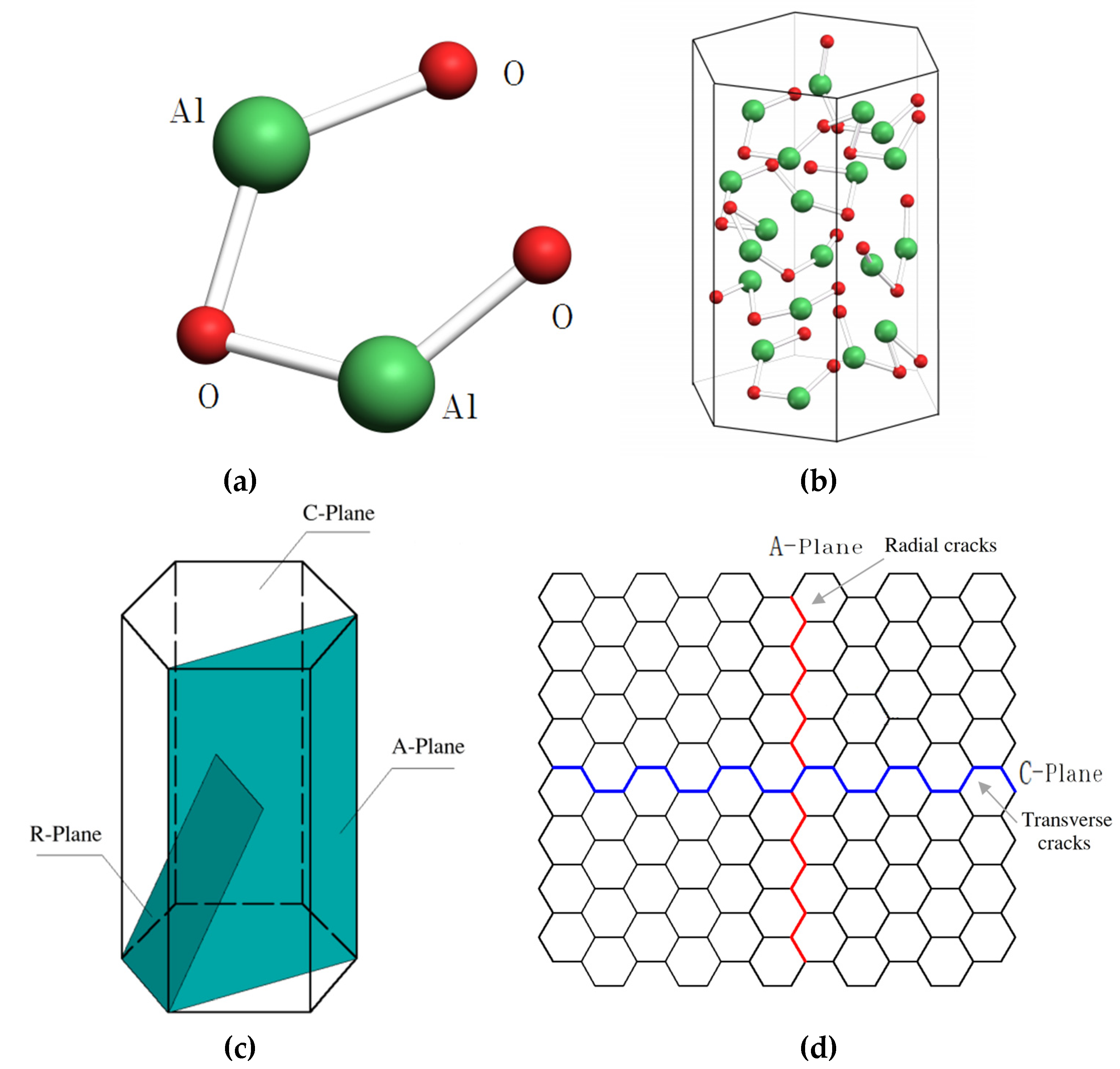
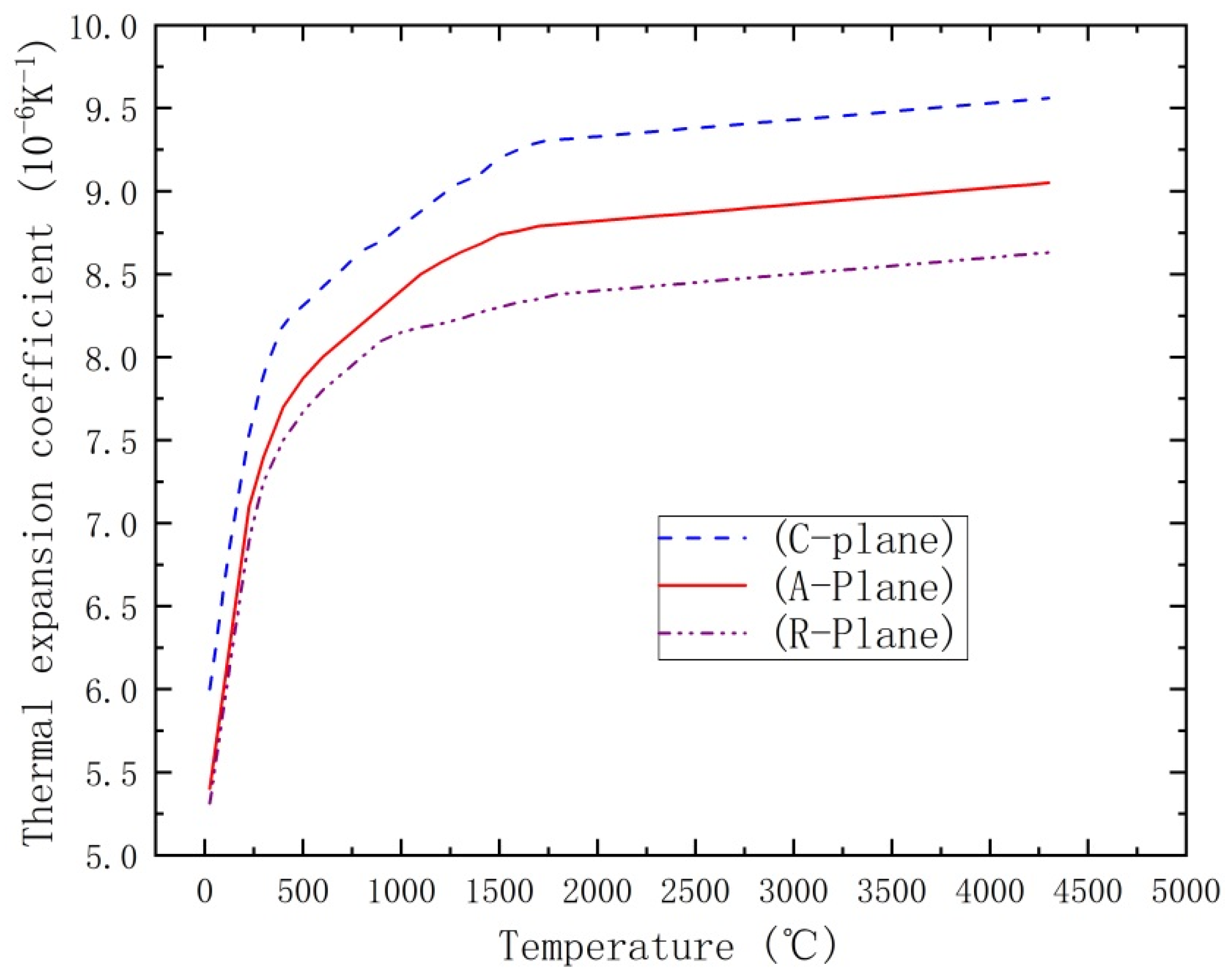
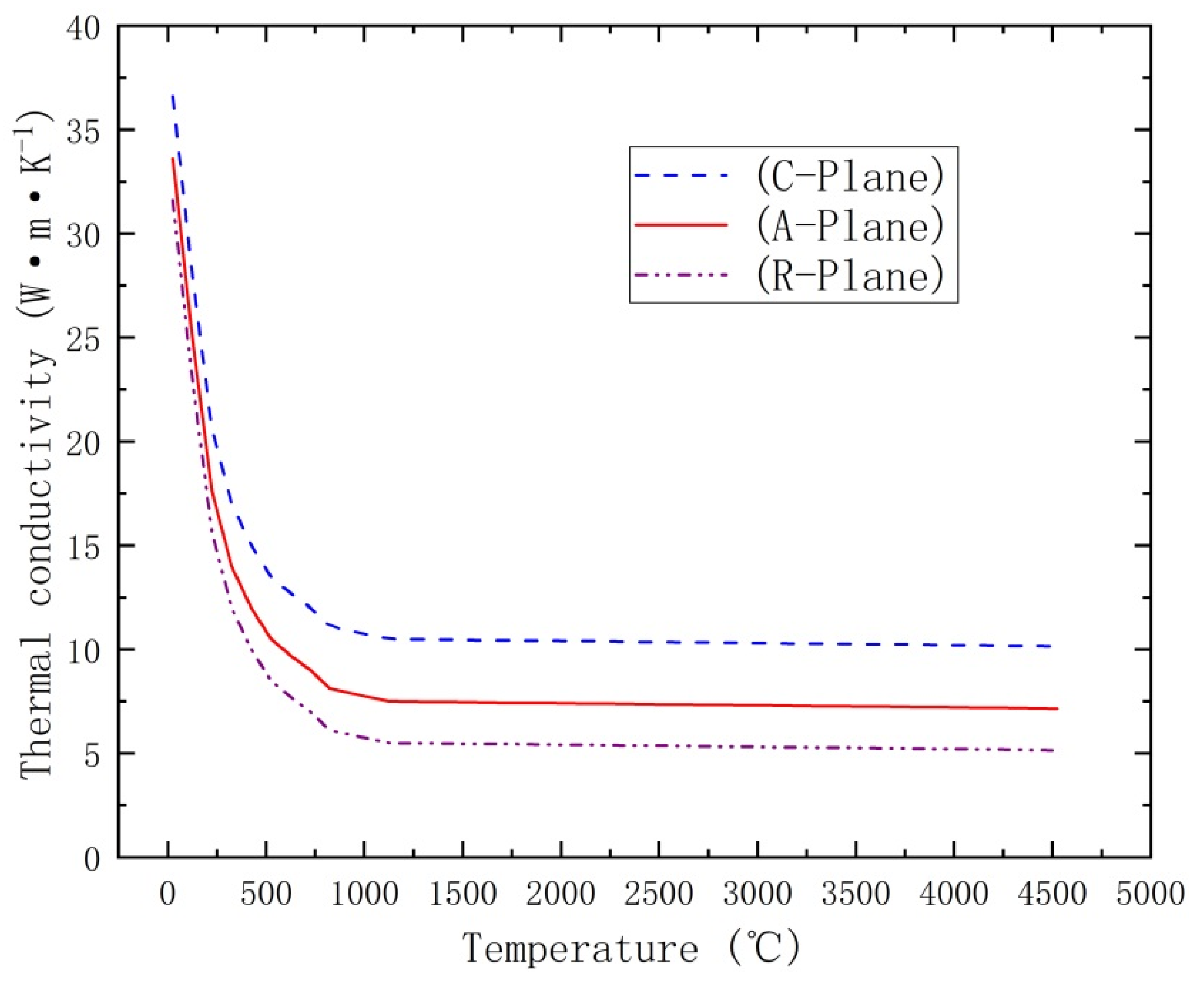
2.1. Sapphire Material

Sapphire material is composed of Al2O3, which has a hexagonal lattice structure. The physical and chemical parameters of sapphire are shown in Table 1. It is commonly used in A and C sections. Figure 1a shows a molecule formed by the covalent bonding of three oxygen atoms and two aluminum atoms; Figure 1b shows the crystal structure of sapphire material, where the red dots are oxygen ions, and the green dots are aluminum ions. The cut surface of sapphire material is shown in Figure 1c, and Figure 1d is the cutting schematic diagram. The c-direction cutting is flat and easily cut; in addition, it does not easily split. However, the cutting edge collapses easily, and the cutting process is not mature. In addition, the processing modes of planes C and A are different, and the efficiency and quality of processing are also affected.
Some studies indicate that the cutting surface cracks of A-Plane sapphires include radial and transverse cracks, while the cutting subsurface cracks of C-Plane sapphires are mainly transverse cracks [24,25,26]. This is shown in Figure 1d, where red lines are radial cracks and blue lines are transverse cracks. Due to sapphire being a hard and brittle material, it easily cracks, fragments, and delaminates; in addition, problems such as edge collapse, edge fracture, tool wear, and other defects are observed during traditional mechanical processing. Moreover, it is difficult to process sapphire by traditional mechanical processing methods. Figure 2 shows microscope photos of sapphire processed by mechanical action at 50 times, 100 times, and 200 times magnification.

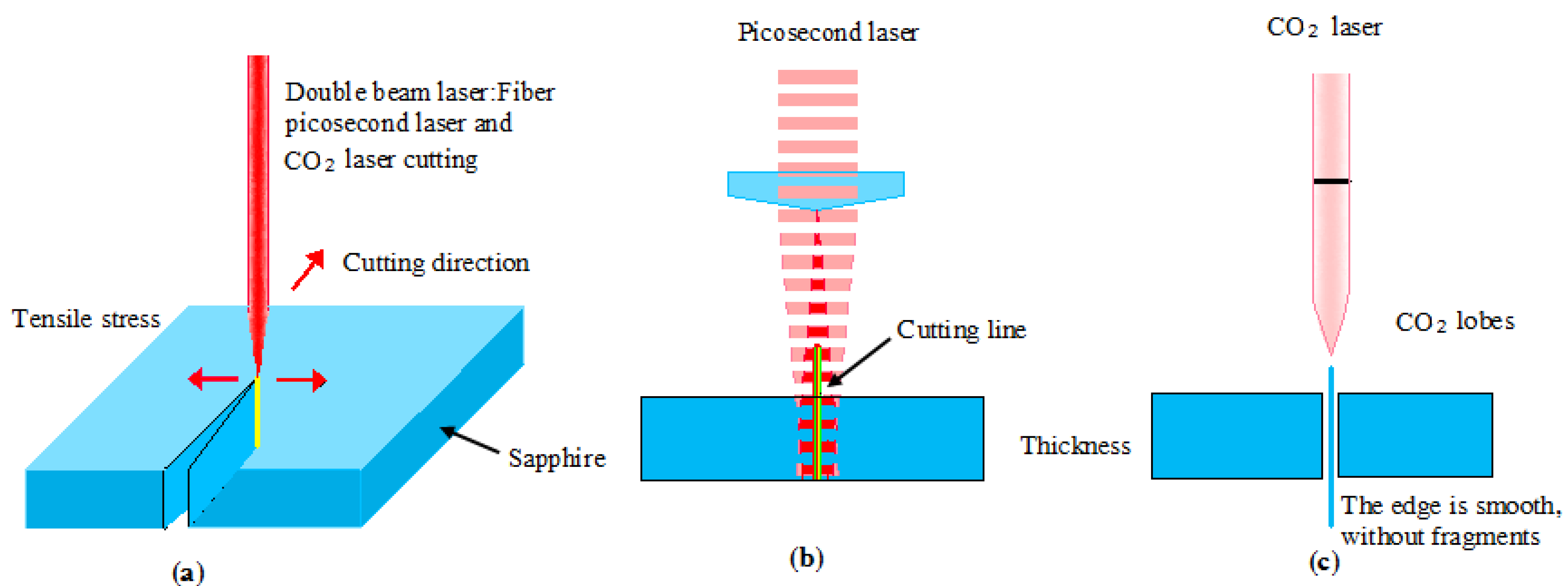
2.2. Principles of Ultrafast Double-Laser Cutting Machining

In the process of ultrafast laser photochemical processing, energy is injected into a very small action area very quickly. The instantaneous deposition of high energy density changes the electron absorption and motion mode, which avoids the linear absorption, energy transfer, and diffusion of other laser-based methods and fundamentally changes the interaction mechanism between laser and matter. In the removal process, effective control and machining accuracy are realized according to the dynamic law of the material and the ultrashort pulse photon.
Updated from previous studies [27,28,29,30], Figure 3a shows that the double-laser-beam cutting method controls the picosecond laser beam through the laser cutting head, focusing on material perforation; with the X/Y high-speed platform moving at a speed of up to 200 mm/s, it forms the required cutting line. A CO2 laser is then used to heat the cutting line; Figure 3b shows a picosecond laser beam focused according to the preset cutting path and the sapphire material’s relative movement. The laser beam is focused on the sapphire material to form a cutting layer by controlling the laser’s spot energy; the focal depth of the laser beam focuses on the sapphire material, and the laser energy and action time directly affect the temperature gradient of the action area. Figure 3c shows that the two lasers cutting path of are the same, and the cutting lines completely overlap. The rapid separation of sapphire was carried out by the CO2 laser that repeated the picosecond laser’s cutting route. By using this method that combines a fiber picosecond laser with a CO2 cutting laser, the cutting of sapphire material was greatly improved, particularly in terms of efficiency and accuracy.

2.3. Analysis of Laser Cutting

The change in the temperature field during the interaction between the ultrafast laser and the sapphire material was simulated. The modified three-dimensional heat conduction equation is as follows (Ref. [31]):
ρ c T t x ( K T x ) y ( K T y ) z ( K T z ) = Q 1 ( x , y , z , t ) + Q 2 ( x , y , z , t )
where K is the thermal conductivity, ρ is the density, c is the specific heat capacity, T is the temperature, t is the time, Q 1 ( x , y , z , t ) is the intensity of the picosecond laser heat source, and Q 2 ( x , y , z , t ) is the intensity of the CO2 laser heat source. In practice, the above parameters are different under different temperature conditions. Assuming that each parameter is independent of temperature, the equation can be simplified as follows:
ρ c T t K 2 T = Q 1 ( x , y , z , t ) + Q 2 ( x , y , z , t )
According to the spatial distribution of Gaussian beams, the ultrashort pulse and the CO2 beam pulse can be expressed as follows (Refs. [32,33]):
I ( x , y , z ) = 2 I 0 π R L 2 ( Z ) exp ( 2 ( x 2 + y 2 ) R L 2 ( Z ) )
where I 0 is the peak power and R L is the spot radius. R L ( Z ) is expressed as in [33,34].
R L ( Z ) = R 0 L 2 + 4 θ L 2 ( z 0 z ) 2
The finite element method is used to solve for the cutting temperature distribution of sapphire material at the next moment for cases involving short time intervals. In this way, the finite element method is used to divide the grid in the spatial domain. The finite element equation of temperature control is as follows:
[ K ] { T } + [ C ] { T ˙ } = { Q 1 } + { Q 2 }
where [ C ] is the ultrafast double-laser specific heat capacity matrix; [ K ] is the ultrafast double-laser heat conduction matrix; { T } and { T ˙ } are column vectors of node temperature change and node temperature change rate, respectively; { Q 1 } and { Q 2 } is the ultrafast laser and CO2 laser energy vector.
It is assumed that there is no radiation or heat convection on the surface of the processed sapphire materials, and the sapphire is regarded as an adiabatic surface. Different models and methods are adopted to obtain approximate analytical or numerical calculations for determining temperature field changes. Our hypotheses were made as follows: (1) the sapphire material being heated is isotropic; (2) each thermal parameter of the sapphire material is treated as a constant; (3) for the radiation and convection of the surface, only the heat conduction of the sapphire material surface is considered. By setting double-laser cutting parameters consistent with the design to simulate the changes in the temperature field, the temperature changes in the sapphire slices along the thickness direction are observed.
Sapphire cracking depends on technological parameters, such as the temperature gradient. If the temperature gradient in the sapphire is too large, it increases the thermal stress, causes an increase in dislocation density, and leads to sapphire cracking. If the temperature field is not reasonable, then the temperature gradient is too large, the cooling rate is too fast, etc. This can cause thermal stress on the sapphire material; relative deformations can be produced, and sapphire cracking occurs. Therefore, the temperature gradient in the sapphire material must be reduced to prevent sapphire cracking.

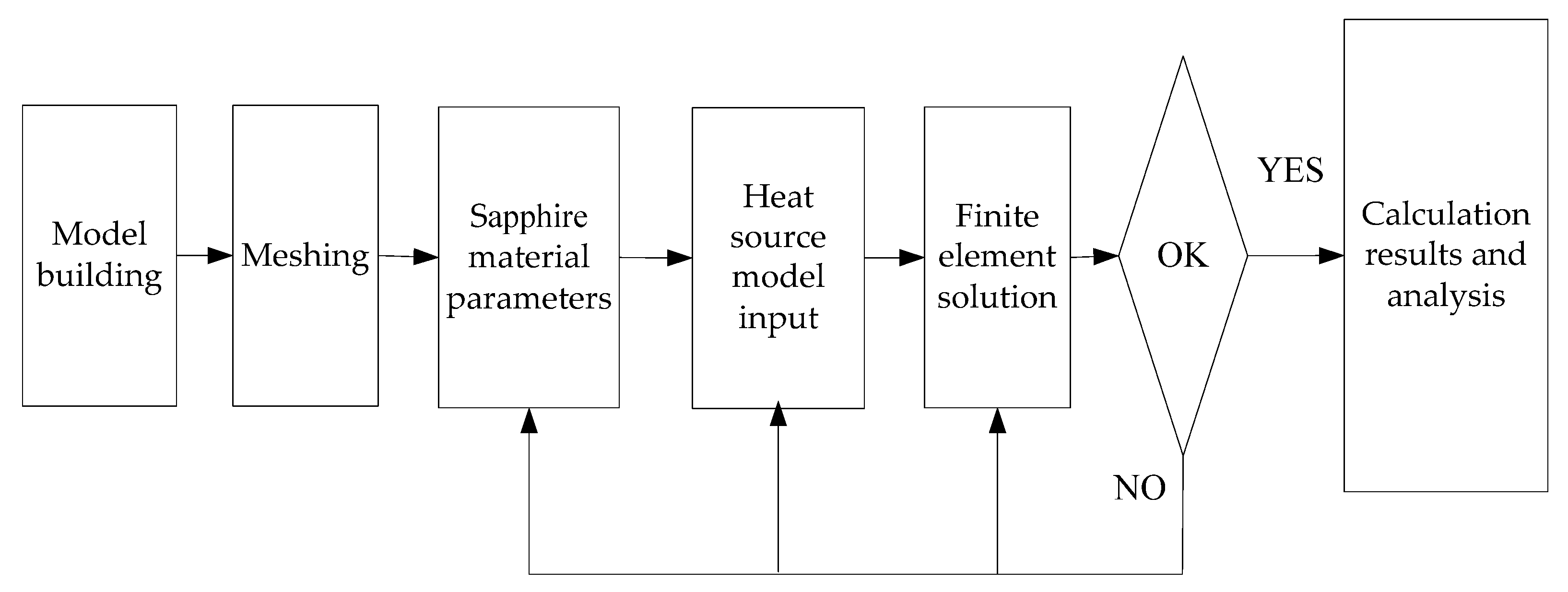
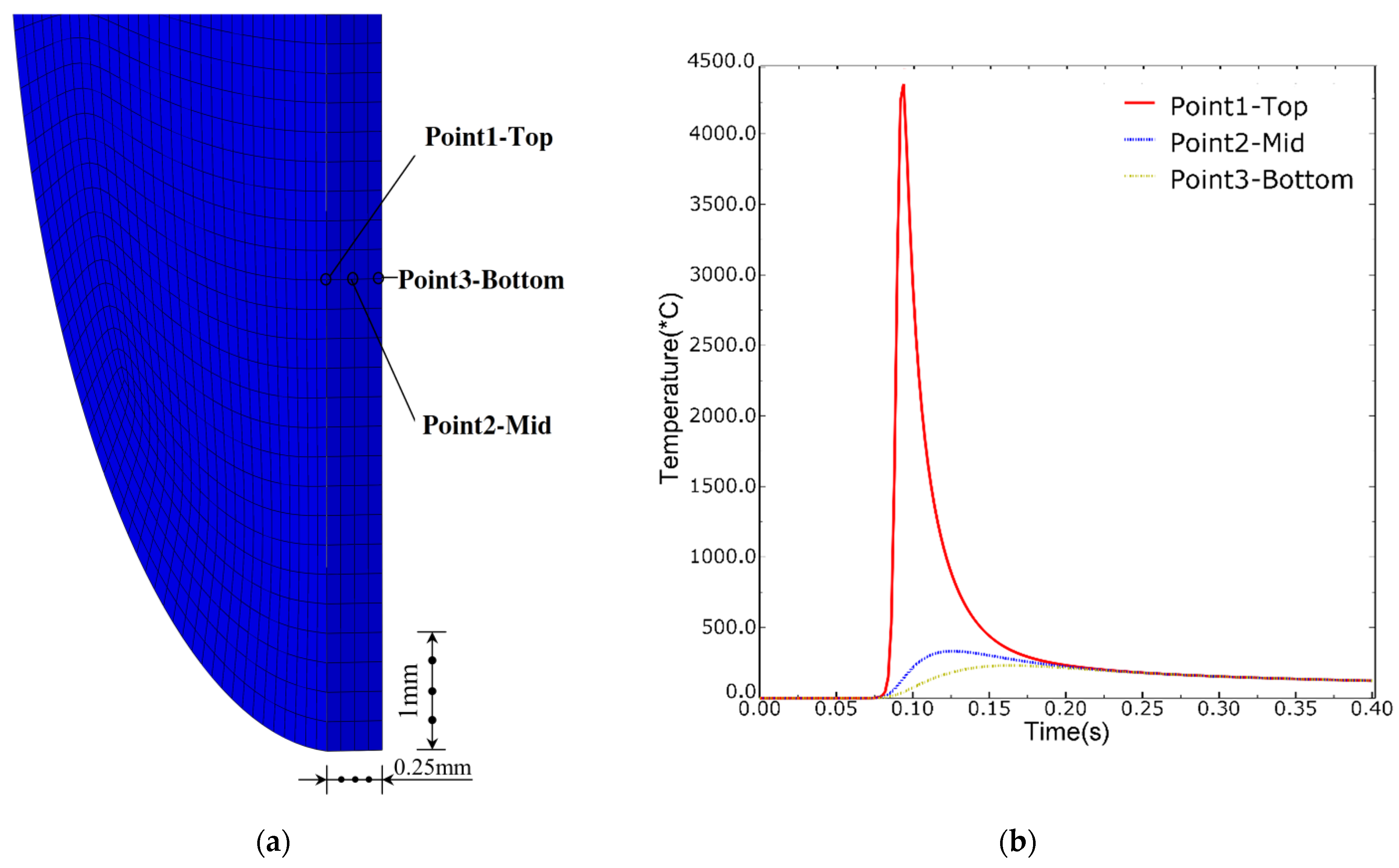
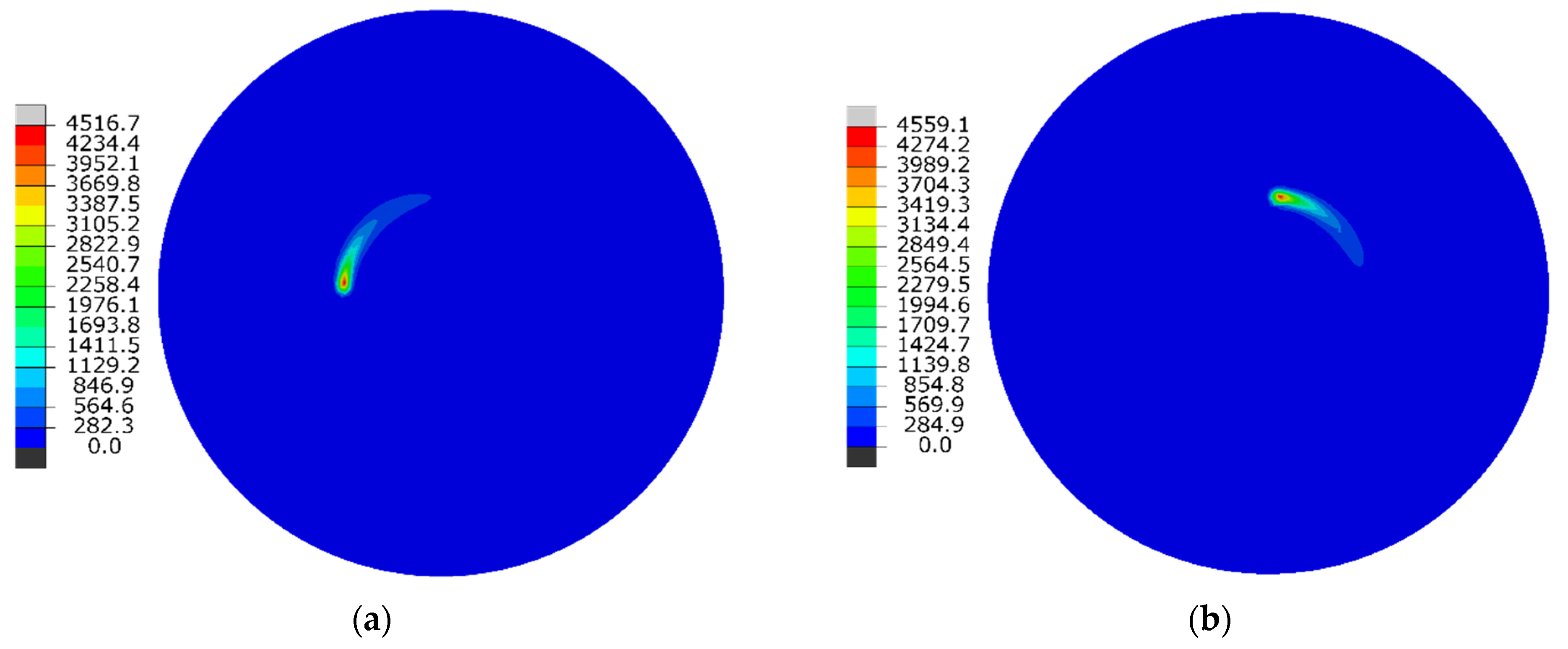
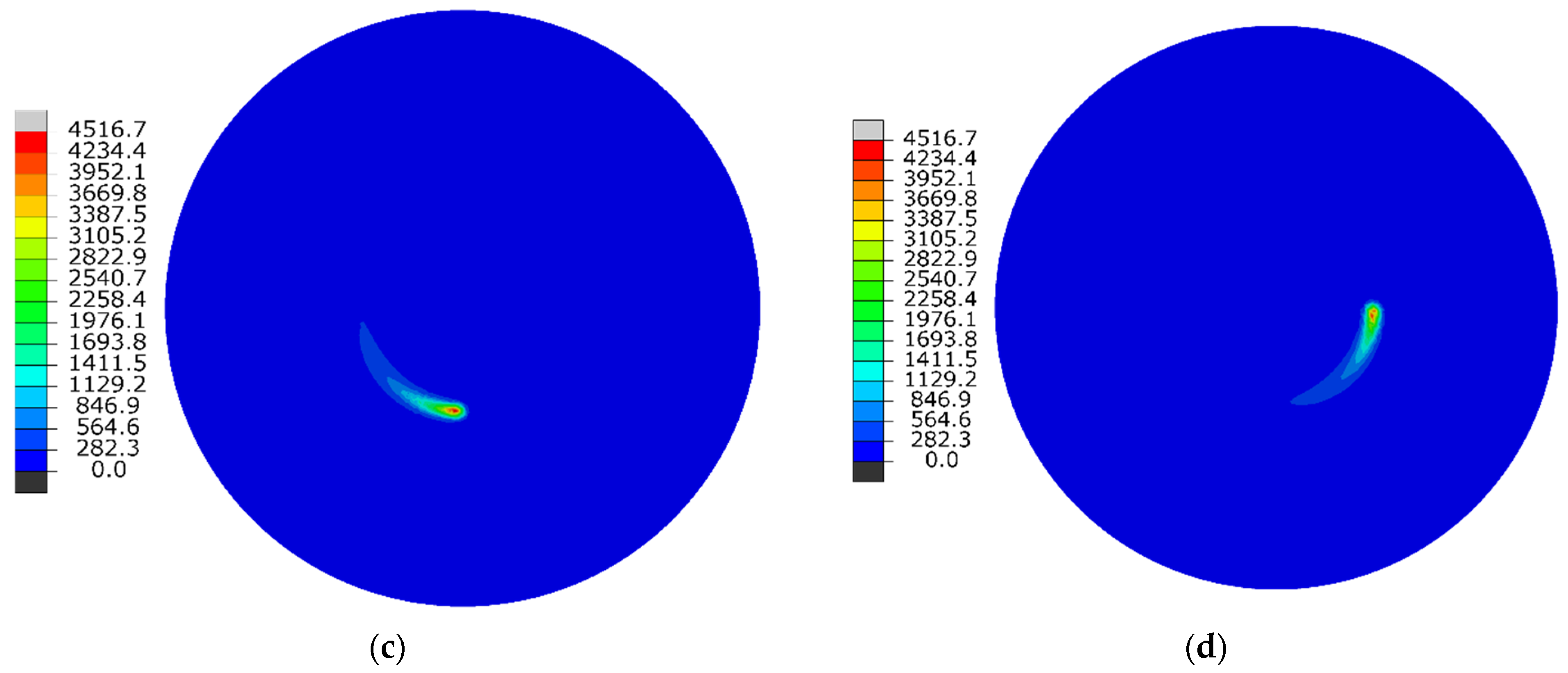
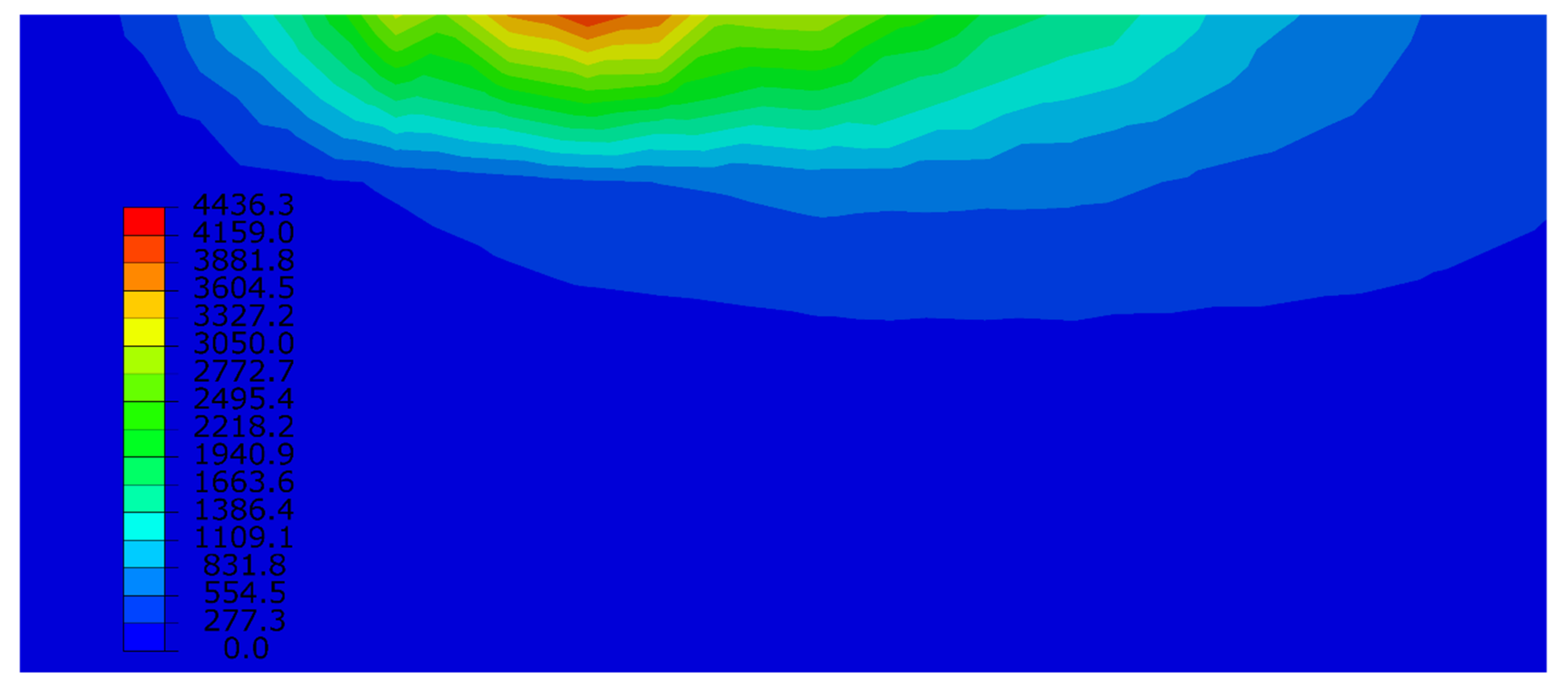
2.4. Temperature Simulation and Analysis

The change in the temperature field during the interaction between the ultrafast laser and the sapphire material was simulated. In the simulation process, parameters such as temperature, heat flux, thermal conductivity, and the specific heat of the surrounding environment were defined. The initial temperature field of the solid module was defined in ABAQUS software. When the initial temperature field of the shell element is defined, the temperature of the cross-section and the temperature in the element plane must also be defined. Like the body element, the temperature of the shell element can be read from existing heat transfer analysis results. ABAQUS provides definitions of conductivity, specific heat, density, modulus of elasticity, Poisson's ratio, and other parameters that vary with the temperature field and field variables. The temperature simulation flow diagram is shown in Figure 4.
In terms of types of thermal analysis, ABAQUS provides steady-state analysis, transient analysis, and nonlinear analysis. The numerical simulation parameters are shown in Table 2.
ABAQUS provides various forms of temperature designation, heat flux designation, convective boundary condition designation, definitions of radiation in the surrounding environment, and the setting of natural boundary conditions and initial conditions. For the contact problem in thermal analysis, ABAQUS provides a thermal “contact” method that simulates heat transfer in the contact position through interfacial heat transfer, thermal interaction, gap heat transfer, gap radiation, and other methods.
The relationships between the thermal expansion coefficient varies with the temperature of sapphire crystal are shown in Figure 5. It can be seen from Figure 5 that the thermal expansion coefficients of these three crystal directions all increase with increases in temperature. In the temperature range of 50–750°C, the thermal expansion coefficients increase greatly with increases in temperature. Such large increases promote the generation of strong thermal stress in the crystal and make the crystal more likely to crack. It can be seen that at the same temperature, the coefficient of thermal expansion in the c-direction is the largest. This is consistent with the reports in [35,36,37]. Curves illustrating the thermal diffusivity vs. the temperature of sapphire are shown in Figure 6. It can be seen from Figure 6 that the thermal conductivity of sapphire crystal decreases with increases in temperature. Regarding heat conduction in sapphire crystal, the main mechanism is phonon heat conduction. With increases in temperature, phonon vibration energy increases and frequency accelerates, so the phonon free path further reduces, thus reducing the thermal conductivity.
The finite element simulation mesh model of sapphire is shown in Figure 7a, and it is a finite element mesh division; the temperature simulation is shown in Figure 7b. It can be seen from Figure 7 that the temperature gradient changes differently in the top and bottom regions of the laser. At Point 1-Top, the temperature is 4300 degrees, which is greater than the boiling point; this value is higher than the temperature change at Point 3-Bottom.
Figure 8 shows the distribution map of the sapphire temperature field at a certain time; it is symmetrically cut along the center of one side of the model. The dark color is the temperature field, and the light color is the laser’s heat-affected zone. The heat-affected zone on the sapphire surface is small, and its outer edge is parallel to the cutting line. The temperature field describes the relationship between temperature distribution and time at a given point in the sapphire. As can be seen from Figure 8a–d, the laser cutting completed one circle in 0.4 s. The temperature field of the cut surface of the sapphire material at 0.1 s is shown in Figure 9, where the ultrafast laser’s energy is transferred to the inside in 0.1 s, which is a very short period of time, and the temperature of the laser’s heat-affected area is gradually reduced.

3. Experimental Equipment and Method

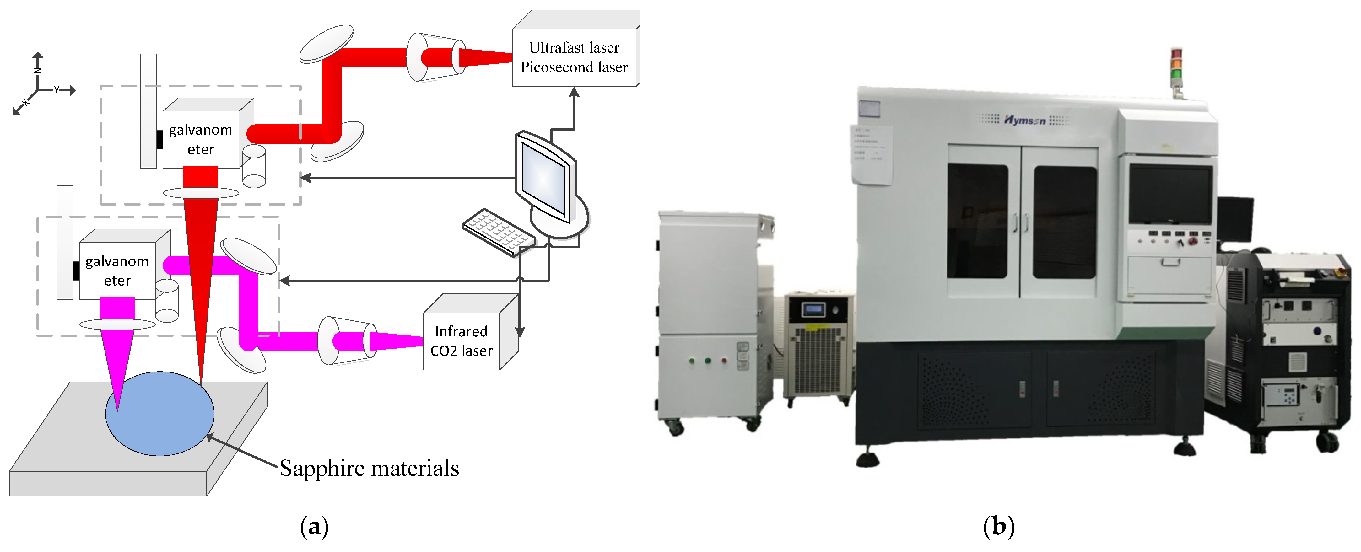
3.1. Experimental Equipment

The test-bed consisted of an ultrafast picosecond laser, a CO2 laser, a beam conversion system, a cooling system, a control system, a working system, etc. The maximum power of the picosecond laser was 40 W. The experimental equipment was an SEM and an optical microscope, and the edge-breaking size [38,39] and edge visual effect of the cutting edge were evaluated. Details of the ultrafast double-beam test are shown in Figure 10. A schematic diagram of dual-beam picosecond laser cutting is shown in Figure 10a, and a photograph of the laser-cutting equipment is shown in Figure 10b.

3.2. Test Materials, Laser Parameters, and Methods

To remove the brittle material more uniformly and improve the removal efficiency, the trajectory was scanned several times in a cycle, and the focus compensation was realized using a dual beam. Sapphire materials were selected for the experiment. Laser parameters were as follows: the picosecond laser wavelength was 1064 nm, the picosecond power was 40 W, the repetition frequency was 100 kHz, the beam quality M2 was 1.3, and cycle scanning times were 10–100. The CO2 laser power was 100 W, the wavelength was 10,600 nm, and the single-pulse energy was 1 mJ. The parameters are shown in Table 3. After the experiment, the surface cutting precision of the samples was observed and measured by field emission scanning electron microscopy and an optical microscope. The influences of average power, scanning speed, repetition frequency, and scanning times on the heat-affected zone were studied. The overall focus was the optimization, by experimental research, of double-beam laser processing parameters for edge preparation in the cutting of sapphire materials using a picosecond laser and CO2 laser.

4. Results and Discussion

With an increase in the intensity of the ultrafast picosecond laser, the chipping size of the top and bottom regions of sapphire increases, but the chipping size of sapphire is less than 4 μm. The serrated surface of the top after machining is mainly caused by the spot separation phenomenon due to the low laser frequency. The serrated surface can be avoided by changing the cutting speed of the ultrafast picosecond laser as well as its repetition frequency; when the laser energy density increases to a certain level, the front edge collapse size reaches saturation.

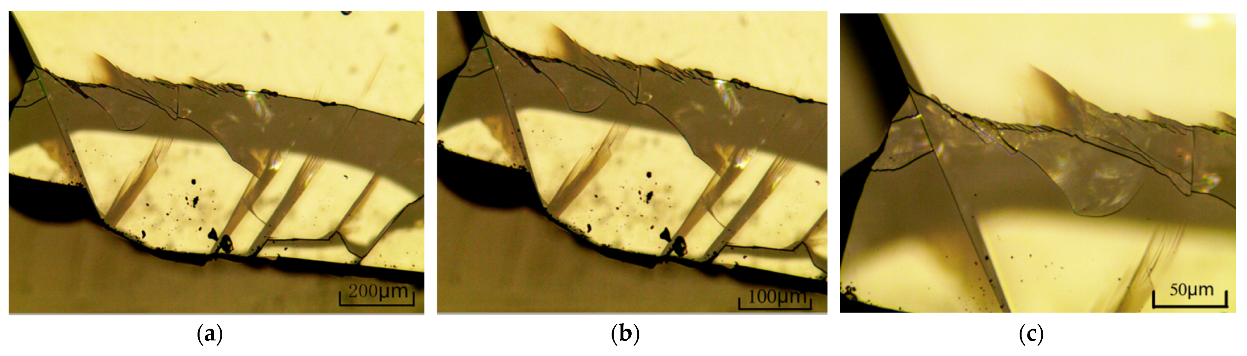
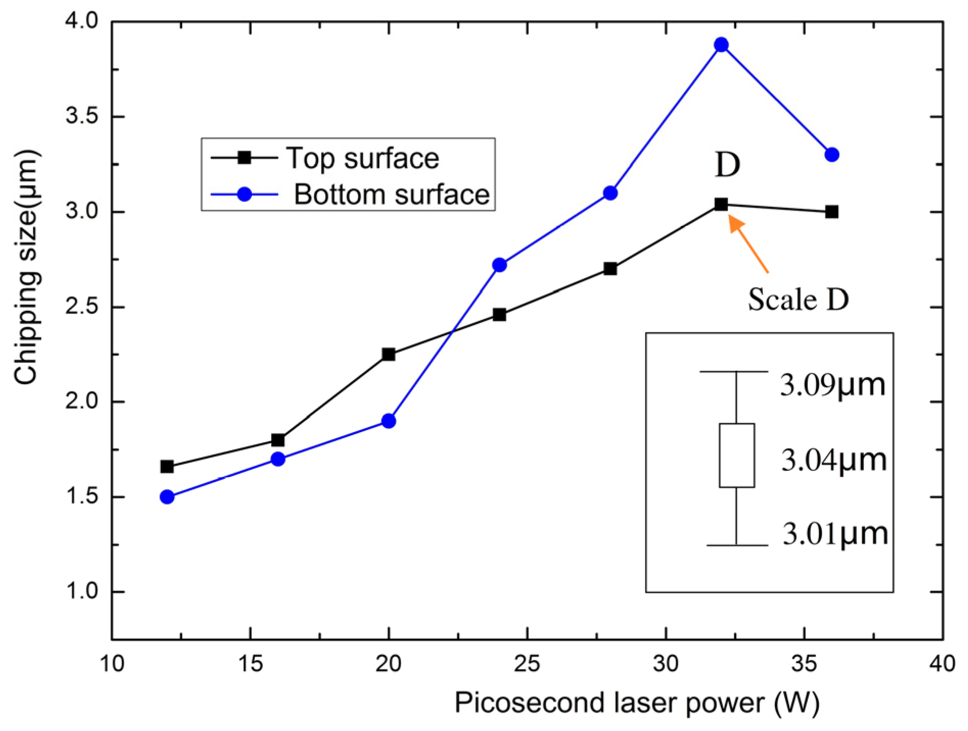
4.1. Influence of the Laser Cutting of Sapphire on the Chipped Edge Phenomenon

The power and cutting speed of the double laser affect the quality of sapphire cutting. Laser energy is the main energy source in the laser cutting of sapphire [40,41]. The energy of sapphire irradiated per unit of time is determined by the laser power and scanning speed, and laser power has an important impact on cutting quality. For a given sapphire material and laser power, the cutting speed of sapphire is proportional to the laser power as long as it is above the threshold value. That is, increasing the power of the picosecond laser can improve the cutting speed. When cutting sapphire materials with a picosecond double-laser beam, if other process parameters remain unchanged, the picosecond laser cutting speed has a relative adjustment range, and the CO2 laser slices through the material by cutting along the same path as the picosecond laser.
The chipping size test, as analyzed by microscope, is shown in Figure 11. Chipping size under varying laser powers is shown in Figure 12, which shows the changes in edge breakage on the top and bottom sapphire surfaces. Laser energy is a very important factor affecting the amount of sapphire edge breakage. The greater the laser energy density is, the more obvious the edge breakage phenomenon is, and the larger the edge size is. It can be seen from the figure that the edge breakage length is very small, less than 4 μm, after picosecond and CO2 cutting. Under the same material conditions, the laser power directly determines the change in the temperature gradient. This is seen in Figure 12, the results of which represent experiments that were each repeated more than three times in different regions to form error bars for the roughness measurements. Point D’s error bar, with scale, is shown in Figure 12 to reveal the difference in roughness.

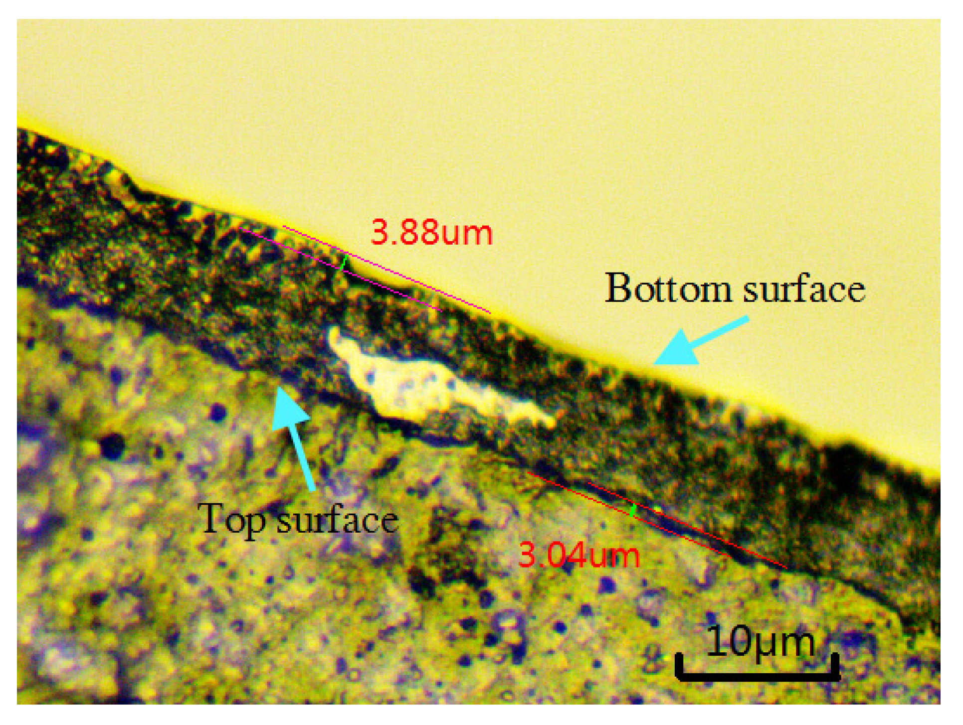
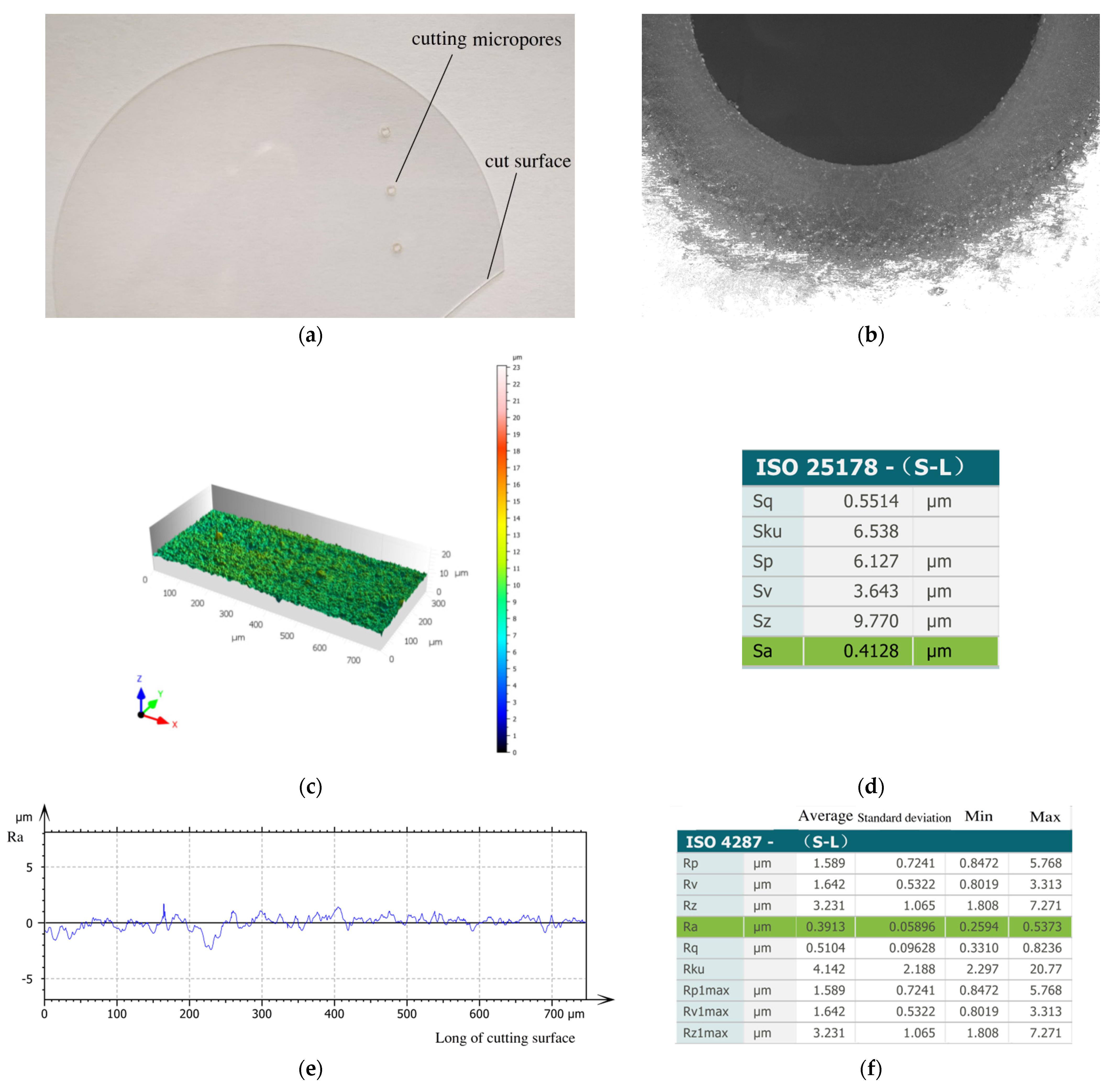
4.2. Test for Sapphire Cutting

After optimizing the process parameters and comparing picosecond single-beam cutting with infrared picosecond and CO2 laser double-beam cutting, the test for sapphire ultrafast double-laser beam cutting is shown in Figure 13.
A photograph of cutting micropores is shown in Figure 13a. SEM scanning images of the sapphire microporous cutting surface are shown in Figure 13b. A microscope observation edge collapse effect test is shown in Figure 13c, with a cutting surface length of 700 microns; surface roughness changes are evaluated by means of the confocal microscope test. Surface 3D morphology and Sa are shown in Figure 13c,d, respectively. Sa is roughness based on cutting regional topography, which was found to be as high as 0.4128 μm. Ra is a parameter used to evaluate roughness based on the line contour method, and its values are shown in Figure 13e,f. This represents the shape and roughness of the cut end face area. The average Ra is as high as 0.3913 μm, and the minimum Ra is 0.2594; because this is a low roughness number, we can clearly see that the cutting quality is very good. It can be seen that the cutting surface quality produced by the picosecond double-beam method is smooth and exhibits no obvious carbonization, with low thermal stress and thermal influence.

5. Conclusions

The simulation of the laser cutting temperature field provided guidance for the experiment and was consistent with the experimental results. Using an ultrafast double-laser-beam cutting test-bed and employing optimized matching with reasonable laser process parameters, the characteristic size and micro-morphology of sapphire materials after processing were studied. The new ultrafast double-laser processing method proposed in this paper can prevent the problem of cutting edge breakage in sapphire crystal materials and provide an effective processing method for the cutting of hard and brittle materials, as demonstrated by the fact that the average Ra of the cutting surface was 0.3913 μm and the chipping size was less than 4 μm.

Author Contributions

Conceptualization, H.X. and W.Z.; methodology, Y.Z. and M.L.; investigation, G.Z.; writing—original draft preparation, H.X.; writing—review and editing, W.Z.; supervision, M.L. and G.Z. All authors have read and agreed to the published version of the manuscript.

Funding

This work was financially supported by the Shenzhen Science and Technology Plan (grant nos. GJHZ20180416164715805 and JSGG20210420091802007), the Science and Technology Project of Guangdong Province (grant no. 2021A0505030013), the Scientific Research Project of General Universities in Guangdong Province (grant no. 2021KCXTD058), and the Department of Science and Technology of Guangdong Province (grant no. 2020B1212060067).

Institutional Review Board Statement

Not applicable.

Informed Consent Statement

Not applicable.

Data Availability Statement

Data underlying the results presented in this paper are available upon request by contact with the corresponding author.

Acknowledgments

We would like to acknowledge the contributions of the theory of ultrafast lasers and cutting technology of sapphire materials to this paper.

Conflicts of Interest

The authors declare no conflict of interest.

References

  1. Strickland, D.; Mourou, G. Compression of amplified chirped optical pulse. Opt. Commun. 1985, 56, 219–221. [Google Scholar] [CrossRef]
  2. Ashkenasi, D.; Rosenfeld, A.; Varel, H.; Wähmer, M.; Campbell, E.E.B. Laser processing of processing of sapphire with picosecond and sub-picosecond pulses. Appl. Surf. Sci. 1997, 120, 65–80. [Google Scholar] [CrossRef]
  3. Kaiser, A.; Rethfeld, B.; Vicanek, M.; Simon, G. Microscopic processes in dielectrics under irradiation by sub-picosecond laser pulses. Phys. Rev. B 2000, 61, 11437–11450. [Google Scholar] [CrossRef]
  4. He, C.; Zibner, F.; Fornaroli, C.; Ryll, J.; Holtkamp, J.; Gillner, A. High-precision Helical Cutting Using Ultra-short Laser Pulses. Phys. Procedia 2014, 56, 1066–1072. [Google Scholar] [CrossRef]
  5. Wang, Z.; Zhao, Q. Friction reduction of steel by laser-induced periodic surface nanostructures with atomic layer deposited TiO2 coating. Surf. Coat. Technol. 2018, 344, 269–275. [Google Scholar] [CrossRef]
  6. Pronko, P.P.; VanRompay, P.; Horvath, A.; Loesel, C.F.; Juhasz, T.; Liu, X.; Mourou, G. Avalanche ionization and dielectric breakdown in silicon with ultrafast laser pulses. Phys. Rev. B 1998, 58, 2387–2390. [Google Scholar] [CrossRef]
  7. Stonge, L.; Detalle, V.; Sabsabi, M. Enhanced laser-induced breakdown spectroscopy using the combination of fourth-harmonic and fundamental Nd:YAG laser pulses. Spectrochim. Acta Part B 2002, 57, 121–135. [Google Scholar] [CrossRef]
  8. Scaffidi, J.M.; Angel, S.; Cremers, D.A. Emission enhancement mechanisms in dual pulse LIBS. In Analytical Chemistry; American Chemical Society: Washington, DC, USA, 2006; pp. 25–32. [Google Scholar]
  9. Kondratenko, S.V.; Borisovskiy, V.Y.; Naumov, A.S. New Laser Cutting Technology of Sapphire Wafers on Crystals. Adv. Mater. Res. 2013, 2291, 30–34. [Google Scholar] [CrossRef]
  10. Li, C.Q.; Wu, W.L.; Zuo, H.B.; Zhang, M.F. Analysis of Fracture Surface for Sapphire Cut by Long Pulse Laser. J. Synth. Cryst. 2010, 39, 997–1001. [Google Scholar]
  11. Fang, X.; Dou, J.; Dong, X.; Duan, W. Research on sapphire micro-blind-hole machining based on femtosecond laser. Ferroelectrics 2020, 563, 31–44. [Google Scholar] [CrossRef]
  12. Cai, Z.; Gao, X.; Yang, W.; Sun, Z.; Ye, Y. Study on Fiber Laser Cutting of Sapphire Substrate. Laser Optoelectron. Prog. 2015, 52, 081403. [Google Scholar]
  13. Yan, T.; Ji, L.; Ma, R.; Lin, Z. Modification characteristics of filamentary traces induced by loosely focused picosecond laser in sapphire. Ceram. Int. 2020, 46, 16074–16079. [Google Scholar] [CrossRef]
  14. Hao, Y.; Sun, M.; Guo, Y.; Shi, S.; Pan, X.; Pang, X.; Zhu, J. Asymmetrical damage growth of multilayer dielectric gratings induced by picosecond laser pulses. Opt. Express 2018, 26, 8791–8799. [Google Scholar] [CrossRef] [PubMed]
  15. Wang, X.D.; Michalowski, A. Laser drilling of stainless steel with nanosecond double-pulse. Opt. Laser Technol. 2009, 41, 148–153. [Google Scholar] [CrossRef]
  16. Pan, Y.; Zhang, H.; Ni, X. Millisecond laser machining of transparent materials assisted by nanosecond laser. Opt. Express 2015, 23, 765–771. [Google Scholar] [CrossRef]
  17. Yan, T.; Ji, L.; Li, L.; Wang, W.; Lin, Z.; Yang, Q. Submicron Fine Cutting-Surface of Sapphire Obtained by Chemical Corrosion Assisted Picosecond Laser Filamentation Technology. Chin. J. Lasers 2017, 44, 1002002. [Google Scholar]
  18. Wang, Q.; Zhang, Q.; Zhang, Z.; Wang, W.; Xu, J. Material removal and surface formation mechanism of C-plane sapphire in multipass ablation by a nanosecond UV laser. Ceram. Int. 2020, 46, 21461–21470. [Google Scholar] [CrossRef]
  19. Haloui, H.; Lee, T.; Müllers, L. Cutting Glass, Sapphire, Ceramics and Other Brittle Materials. Photonics Views 2020, 3, 23–25. [Google Scholar] [CrossRef]
  20. Lin, J.; Jiang, F.; Xu, X.; Lu, J.; Tian, Z.; Wen, Q.; Lu, X. Molecular dynamics simulation of nanoindentation on C-plane sapphire. Mech. Mater. 2021, 154, 103716. [Google Scholar] [CrossRef]
  21. Zhang, Q.; Wang, Q.; Zhang, Z.; Su, H.; Fu, Y.; Xu, J. Surface micro-structuring of Sapphire by a Q-switched DPSS nanosecond pulsed laser. Mater. Sci. Semicond. Process. 2020, 107, 104864. [Google Scholar] [CrossRef]
  22. Waugh, D.G.; Walton, C.D. Micro-Machining of Diamond, Sapphire and Fused Silica Glass Using a Pulsed Nano-Second Nd:YVO4 Laser. Optics 2021, 2, 169–183. [Google Scholar] [CrossRef]
  23. Wen, Q.; Wang, H.; Cheng, G.; Jiang, F.; Lu, J.; Xu, X. Improvement of ablation capacity of sapphire by gold film-assisted femtosecond laser processing. Opt. Lasers Eng. 2020, 128, 106007. [Google Scholar] [CrossRef]
  24. Wen, Q.; Wei, X.; Jiang, F.; Lu, J.; Xu, X. Focused Ion Beam Milling of Single-Crystal Sapphire with A-, C-, and M-Orientations. Materials 2020, 13, 2871. [Google Scholar] [CrossRef] [PubMed]
  25. Wan, L.; Dai, P.; Li, L.; Deng, Z.; Hu, Y. Investigation on ultra-precision lapping of A-plane and C-plane sapphires. Ceram. Int. 2019, 45, 12106–12112. [Google Scholar] [CrossRef]
  26. Wang, N.; Jiang, F.; Xu, X.; Lu, X. Effects of Crystal Orientation on the Crack Propagation of Sapphire by Sequential Indentation Testing. Crystals 2017, 8, 3. [Google Scholar] [CrossRef] [Green Version]
  27. Pan, A.; Wang, W.; Liu, B.; Mei, X.; Yang, H.; Zhao, W. Formation of high-spatial-frequency periodic surface structures on indium-tin-oxide films using picosecond laser pulses. Mater. Des. 2017, 121, 126–135. [Google Scholar] [CrossRef]
  28. Mishchik, K.; Beuton, R.; Caulier, O.D.; Skupin, S.; Chimier, B.; Duchateau, G.; Chassagne, B.; Kling, R.; Hönninger, C.; Mottay, E.; et al. Improved laser glass cutting by spatio-temporal control of energy deposition using bursts of femtosecond pulses. Opt. Express 2017, 25, 33271–33282. [Google Scholar] [CrossRef]
  29. Zibner, F.; Fornaroli, C.; Ryll, J.; He, C.; Holtkamp, J.; Gillner, A. Ultra-high-precision helical laser cutting of sapphire. In Proceedings of the 2014 33rd International Congress on Laser Materials Processing, Laser Microprocessing and Nanomanufacturing, San Diego, CA, USA, 19–23 October 2014. [Google Scholar] [CrossRef]
  30. Li, Y.; Liu, H.; Hong, M. High-quality Sapphire Microprocessing by Dual-beam Laser Induced Plasma Assisted Ablation. Opt. Express 2019, 28, 6242–6250. [Google Scholar] [CrossRef]
  31. Chichkov, B.N.; Momma, C.; Nolte, S.; Von Alvensleben, F.; Tünnermann, A. Femtosecond, picosecond and nanosecond laser ablation of solids. Appl. Phys. 1996, 63, 109–115. [Google Scholar] [CrossRef]
  32. Yuze, H.; Khamesee, M.B.; Toyserkani, E. A comprehensive analytical model for laser powder-fed additive manufacturing. Addit. Manuf. 2016, 12, 90–99. [Google Scholar]
  33. DebRoy, T.; Wei, H.L.; Zuback, J.S.; Mukherjee, T.; Elmer, J.W.; Milewski, J.O.; Beese, A.M.; Wilson-Heid, A.; De, A.; Zhang, W. Additive manufacturing of metallic components–process, structure and properties. Prog. Mater. Sci. 2018, 92, 112–224. [Google Scholar] [CrossRef]
  34. Toyserkani, E.; Khajepour, A.; Corbin, S. Laser Cladding; CRC Press: Boca Raton, FL, USA, 2004. [Google Scholar]
  35. Jun, S.C.; Lianhan, Z.; Jiaqi, H.; Fangfang, Z.; Shilie, P.; Yin, H. Study on Thermal Properties of Sapphire Crystal. J. Synth. Cryst. 2015, 44, 2652–2657. [Google Scholar]
  36. Nye, J.F. Physical Properties of Crystals: Their Representation by Tensors and Matrices; Oxford University Press: Oxford, UK, 1998; Volume 106, p. 195. [Google Scholar]
  37. Lu, C.W.; Chen, J.C.; Chen, C.H.; Chen, C.H.; Hsu, W.C.; Liu, C.M. Effects of RF Coil Position on the Transport Processes during the Stages of Sapphire Czochralski Crystal Growth. J. Cryst. Growth 2010, 312, 1074–1079. [Google Scholar] [CrossRef]
  38. Wang, J.; Feng, P.; Zhang, J.; Zhang, C.; Pei, Z. Modeling the dependency of edge chipping size on the properties and cutting force for rotary ultrasonic drilling of brittle materials. Int. J. Mach. Tools Manuf. 2016, 101, 18–27. [Google Scholar] [CrossRef]
  39. Shi, H.; Liu, G.; Yang, G.; Bi, Q.; Zhao, Y.; Wang, B.; Sun, X.; Liu, X.; Qi, H.; Xu, W.; et al. Analytical modelling of edge chipping in scratch of soda-lime glass considering strain-rate hardening effect. Ceram. Int. 2021, 47, 26552–26566. [Google Scholar] [CrossRef]
  40. Link, S.; Burda, C.; Nikoobakht, B.; El-Sayed, M.A. Laser-Induced Shape Changes of Colloidal Gold Nanorods Using Femtosecond and Nanosecond Laser Pulses. J. Phys. Chem. B 2000, 104, 104–6152. [Google Scholar] [CrossRef]
  41. Kang, Y.; Derouach, H.; Berger, N.; Herrmann, T.; L’huillier, J. Experimental research of picosecond laser based edge preparation of cutting tools. J. Laser Appl. 2020, 32, 022043. [Google Scholar] [CrossRef]
Figure 1. Structure of sapphire material. (a) Al2O3 covalent bonding. (b) Sapphire crystal structure. (c) Cutting surface of sapphire material. (d) Cutting schematic diagram.
Crystals 12 00867 g001
Figure 2. The fragmentation of sapphire material under mechanical action. (a) 50×. (b) 100×. (c) 200×.
Crystals 12 00867 g002
Figure 3. Schematic diagram of ultrafast double-laser-beam cutting. (a) Double-laser-beam cutting method; (b) Picosecond laser cutting; (c) CO2 laser cutting.
Crystals 12 00867 g003
Figure 4. The temperature simulation flow diagram.
Crystals 12 00867 g004
Figure 5. Thermal expansion coefficient varies with temperature of sapphire crystal.
Crystals 12 00867 g005
Figure 6. Thermal conductivity varies with temperature of sapphire crystal.
Crystals 12 00867 g006
Figure 7. Simulation of the temperature field of brittle sapphire material based on ABAQUS. (a) Finite element mesh division. (b) Temperature curve varies with time.
Crystals 12 00867 g007
Figure 8. Temperature field variation of sapphire laser cutting material based on ABAQUS at different times. (a) t = 0.1 S. (b) t = 0.2 S. (c) t = 0.3 S. (d) t = 0.4 S.
Crystals 12 00867 g008aCrystals 12 00867 g008b
Figure 9. Temperature field variation of cut surface at 0.1 S.
Crystals 12 00867 g009
Figure 10. Ultrafast double-laser beam cutting machine equipment. (a) Schematic diagram of ultrafast double-laser beam cutting. (b) photograph of the laser-cutting equipment.
Crystals 12 00867 g010
Figure 11. Chipping size test analyzed by microscope.
Crystals 12 00867 g011
Figure 12. Chipping size under varying laser powers.
Crystals 12 00867 g012
Figure 13. Test for double-beam cutting sapphire. (a) Photograph of cutting micropores. (b) SEM scanning of microporous sapphire surface. (c) 3D roughness of the cut surface. (d) Sa roughness of the cut surface. (e) Roughness of the cut surface. (f) Ra roughness of the cut surface.
Crystals 12 00867 g013
Table 1. Physical and chemical parameters of sapphire.
Chemical ElementsDensity
(g/cm3)
Hardness (HV)Thermal Coefficient of ExpansionRefractive IndexMelting
Point (°C)
Boiling Point (°C)
Al2O33.95–4.117005~40 W/(m·°C)1.762~1.77020503500
Table 2. Numerical simulation parameters.
ParametersNumerical ValueParametersNumerical Value
Diameter51 mmLaser spot radius0.05 mm
Thickness0.3 mmCutting speed200 mm/s
Thermal coefficient of expansion5 W/m2The grid size0.25 mm
Picosecond laser power40 WDensity4000 Kg/(m3)
Conductivity5~40 W/(m·°C)Specific heat0.7788 J/(g·K)
Indoor temperature25 °CExpansion coefficient5.2~9.51/10−6 K−1
Table 3. Double-beam laser processing parameters.
Picosecond LaserCO2 Laser
Wavelength1064 nmWavelength10,600 nm
Optical quality<1.2Optical quality<1.3
Power>40 WPower100 W
Pulse width<10 psPulse width1 ns
Cutting speed100–200 mm/sCutting speed50–200 mm/s
Pulse frequency200 kHz–8 MHzPulse frequency10–600 kHz
Publisher’s Note: MDPI stays neutral with regard to jurisdictional claims in published maps and institutional affiliations.

