Article

Stoichiometric Growth of Monolayer FeSe Superconducting Films Using a Selenium Cracking Source

1
Beijing Academy of Quantum Information Sciences, Beijing 100193, China
2
State Key Laboratory of Low Dimensional Quantum Physics, Department of Physics, Tsinghua University, Beijing 100084, China
3
State Key Laboratory of High Performance Computing, College of Computer Science and Technology, National University of Defense Technology, Changsha 410073, China
4
Frontier Science Center for Quantum Information, Beijing 100084, China
*
Authors to whom correspondence should be addressed.
Crystals 2022, 12(6), 853; https://doi.org/10.3390/cryst12060853
Submission received: 27 May 2022 / Revised: 14 June 2022 / Accepted: 15 June 2022 / Published: 17 June 2022
(This article belongs to the Special Issue Superconductors: Materials, Microstructures and Applications)

Abstract

:
As a novel interfacial high-temperature superconductor, monolayer FeSe on SrTiO3 has been intensely studied in the past decade. The high selenium flux involved in the traditional growth method complicates the film’s composition and entails more sample processing to realize the superconductivity. Here we use a Se cracking source for the molecular beam epitaxy growth of FeSe films to boost the reactivity of the Se flux. Reflection high-energy electron diffraction shows that the growth rate of FeSe increases with the increasing Se flux when the Fe flux is fixed, indicating that the Se over-flux induces Fe vacancies. Through careful tuning, we find that the proper Se/Fe flux ratio with Se cracked that is required for growing stoichiometric FeSe is close to 1, much lower than that with the uncracked Se flux. Furthermore, the FeSe film produced by the optimized conditions shows high-temperature superconductivity in the transport measurements without any post-growth treatment. Our work reinforces the importance of stoichiometry for superconductivity and establishes a simpler and more efficient approach to fabricating monolayer FeSe superconducting films.

1. Introduction

Monolayer FeSe grown on SrTiO3 (STO) exhibits a surprisingly high superconducting temperature (40–80 K) in a merely half-nanometer-thick film [1,2,3]. It distinguishes itself from its bulk counterpart in terms of band structure, fermiology, orbital order, magnetic excitations, topological states, and possible pairing symmetry [4,5,6,7,8]. Interfacial charge transfer [9] and electron–phonon coupling [10,11] are thought to play an important role. Intensive investigations have been carried out in the past ten years although more efforts are needed to unravel the mechanisms of superconductivity. One of the challenges that hinder the study has come from the difficulties in sample growth.
Molecular beam epitaxy (MBE) and pulsed laser deposition (PLD) are popular techniques for thin-film growth. PLD has been successful and efficient in growing FeSe films with a moderate thickness (hundred nanometers). The transition temperature Tc is usually close to or below that of the bulk and drops further with decreasing film thickness [12]. PLD has not been able to grow superconducting FeSe films thinner than 10 nm and has suffered from difficulties in controlling the film’s stoichiometry, nucleation, and bonding to the substrate [13]. So far, FeSe films in a monolayer form have been exclusively grown by MBE using a well-known strategy called “adsorption-controlled growth”. The substrate temperate (~400 °C) sits below the evaporating temperatures of Fe and above that of Se [14]. Therefore, the Fe atoms landing on the surface are fully sticking, whereas Se has a low sticking coefficient [15]. As for the Se source, most of the documented experiments used ordinary effusion cells or crackers at uncracking temperatures [1,11,16]. The majority of the thermally evaporated Se species are Se6 and Se5, which are less reactive than smaller ones [17]. As a result, the flux ratio Se:Fe needed to be as high as 5–20 in previous studies to compensate for the low reaction rate [1,10,16,18,19,20].
However, this growth strategy is not exactly applicable to obtaining a stoichiometric FeSe phase, since there could be substantial Fe-vacant phases such as Fe4Se5 and Fe9Se10 in the Se-rich cases [21,22]. Recent studies have clarified that the Fe vacancies lead to a non-superconducting phase of the as-grown films and one must either post-anneal the film or deposit additional Fe atoms to remove the vacancies [20,23,24], which complicates the sample preparation process. The uncertainties in the high Se flux (plus the resulting high Se background pressure), the density of the Fe vacancies, and the post-growth treatment recipe create challenges to obtaining high-quality FeSe films.
In this article, we present a systematic study on FeSe film growth using a Se cracking source. The cracker consists of a reservoir crucible that contains and evaporates the materials, and a cracking tube that breaks the molecules into smaller ones (see the inset of Figure 1). It has been used for MBE growth of other selenide films and found to enhance the reaction efficiency and improve the quality of the films [25,26]. We find the Se flux threshold for FeSe growth is considerably reduced when Se is cracked. Fe vacancies develop in close association with the Se flux, revealed by the intensity oscillations of reflection high-energy electron diffraction (RHEED). An optimized recipe is provided, which yields superconducting monolayer FeSe films without post-growth treatments.

2. Materials and Methods

The sample growth was carried out in a home-built standard MBE system with a base vacuum below 5 × 10⁻¹⁰ mbar. Nb-doped (0.05 wt%) SrTiO3(001) substrates were annealed in the vacuum by direct current heating at 970 °C for 15 min to obtain flat surfaces. For the samples for transport experiments, Fe atoms were deposited on the substrate at 750 °C, forming an insulating Fe-oxide buffer layer. FeSe films and 10-layer FeTe caps were grown by codepositing individual elements. The substrate temperature was ~430 °C for FeSe growth and ~250 °C for FeTe growth, measured by a pyrometer. High-purity Fe and Te were evaporated from Knudsen cells and Se was evaporated from a cracking source.
The source fluxes were measured by a water-cooled quartz crystal microbalance (QCM). The quartz crystal with gold electrodes (INFICON) was operated at 6 MHz. The QCM head was moved to the sample position using a linear motion for the measurements. The Fe flux was kept at ~0.19 layer/min throughout the study at the typical cell temperature of 1090 °C. Samples were monitored during growth by in situ RHEED. The electron energy was 15 keV and the electron beam was along the <100> direction of the substrates for all experiments.
Transport experiments were carried out in an Oxford Instruments TeslatronPT system. Indium lumps were cold-pressed onto the sample as contacts. Standard lock-in techniques were employed to determine the sample resistance in a four-terminal configuration with an excitation current of 1 μA at 13.333 Hz.

3. Results

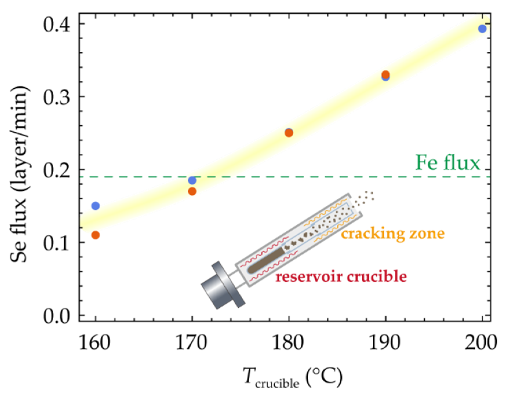
3.1. Source Flux Calibration

To obtain the estimation of the actual source flux for the growth, we first calibrate it using a QCM. The QCM head is maintained at room temperature so that the sticking coefficient can be taken as 1 [15]. We choose the Fe flux equivalent to 0.19 layer FeSe per minute (or 5.3 min per layer) and keep it constant in the following experiments. For the Se source, the vapor mass is primarily determined by the temperature of the crucible (Tcrucible) at the bottom where all the source materials are stored. Hence, we fix the temperature of the cracking zone (Tcracker) at 1000 °C and measure the flux as the function of Tcrucible, as shown in Figure 1. For convenience, the Se source temperature is denoted as Se(Tcrucible/Tcracker) in the unit of °C hereafter.
As expected, the flux of Se increases monotonically with increasing crucible temperature from 160 °C to 200 °C, which is a reliable tuning parameter for optimizing the growth conditions. The two sets of measurements taken a month apart exhibit good agreement for Tcrucible > 170 °C and a larger discrepancy for Tcrucible < 170 °C, as both the stability of the cell and the precision of the QCM are lower for lower fluxes. According to the level of Fe flux, we anticipate that the Se crucible temperature should be higher than 170 °C when growing FeSe films, where the flux is reliable.

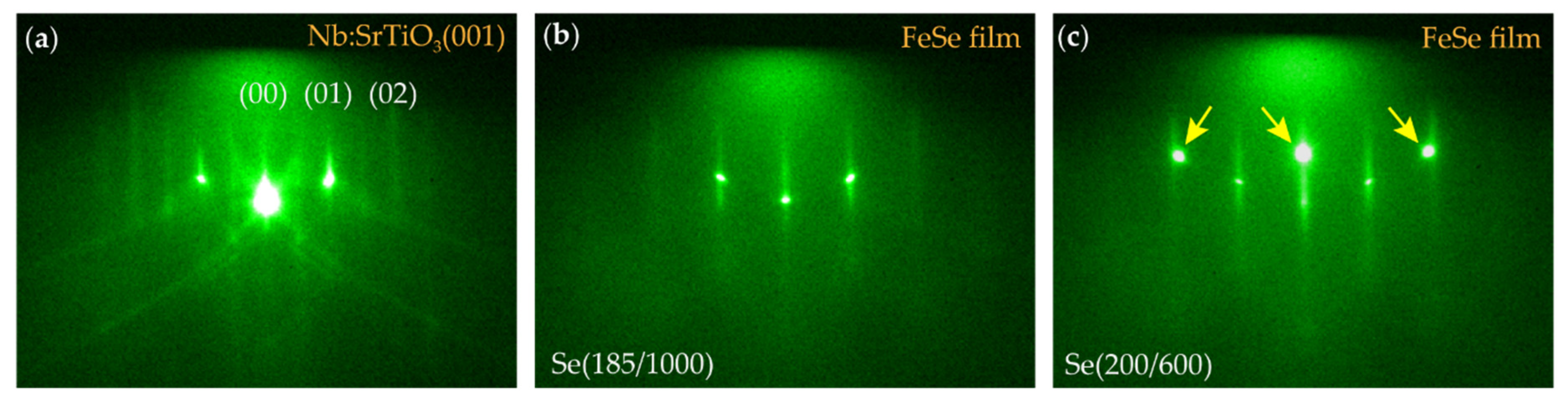
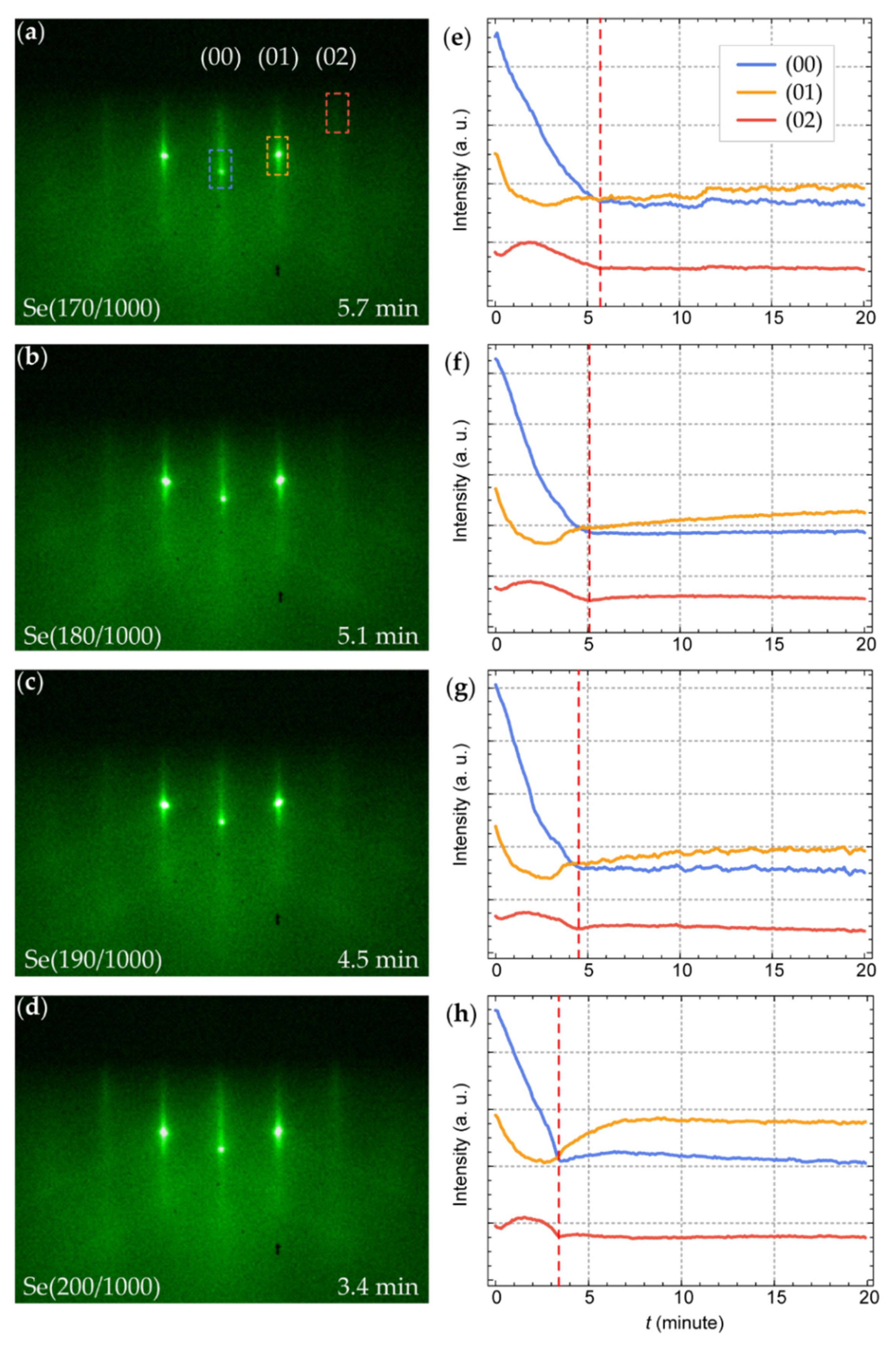
3.2. Impact of Cracked Se Flux on the Growth

The typical RHEED pattern of treated STO is shown in Figure 2a. The bright diffraction spots located on a Laue circle and the clear Kikuchi lines indicate a highly flat surface. After codepositing Fe and Se(185/1000) for 5 min (~1 monolayer), the RHEED image (Figure 2b) indicates the formation of the single-crystalline FeSe film aligned with the STO substrate, which agrees with previous observations [20]. The current Se flux supports the successful growth of monolayer FeSe.
To examine the extent of the effects of cracking Se, we grow another sample using the same conditions but changing the Se to (200/600). Increasing the crucible temperature should increase the quantity of Se exiting the cell, whereas decreasing the cracker temperature to 600 °C disables the cracking. As shown in Figure 2c, intense three-dimensional diffraction spots now pop up (marked by the arrows) in addition to weakened two-dimensional patterns, which is a typical result caused by Se insufficiency. Although the total Se mass is increased, the uncracked Se molecules are not active enough to combine with all the Fe atoms to form into FeSe films, leaving excess Fe clusters or islands. If one were to grow FeSe normally without cracking, the flux should be considerably increased, similar to the traditional method. The contrast between Figure 2b,c demonstrates that the cracking has enhanced the reactivity of Se substantially so that the FeSe films can be grown with a much lower Se flux.
To sort out the optimal conditions for FeSe growth, we carefully adjust the Se flux and observe its effects. When the Se flux is above the threshold, assuming an ideal adsorption-controlled growth of stoichiometric FeSe, the growth rate should be solely determined by the Fe flux regardless of the Se flux. However, we observe clear dependence of the growth rate on the Se flux (Figure 3).
We grow a series of samples using various Tcrucible at 170–200 °C while keeping Tcracker at 1000 °C. All samples show similar RHEED patterns (Figure 3a–d) suggesting a decent two-dimensional growth of FeSe films. We further extract the integrated intensity of the diffraction spots/streaks as the function of the deposition time for each sample (Figure 3e–h). The curves follow a similar trend among different samples. The simultaneous minimum or saturation points on the (02) and (00) lines are the hallmark of the completion of the monolayer [27]. Intriguingly, this point moves earlier in time as the Se flux increases. According to the Fe flux by QCM, it should have taken ~5.3 min to finish the monolayer FeSe film if the composition were stoichiometric. However, in practice, this process is shortened to 3.4 min with a larger amount of Se at (200/1000) and when the amount of Fe is not changed. This behavior can be naturally explained by lower Fe occupation, i.e., the formation of Fe vacancies, which confirms the scenario given by previous studies [20,24]. The higher background intensity in Figure 3d also hints at more disorder caused by defects.
Having understood the behaviors of the growth rate, the stoichiometric growth can be identified when the actual growth time coincides with that calculated by the Fe flux—5.3 min—which is close to the cases in Figure 3e,f. Thus, the optimal Se flux lies around Se(170–180/1000). Comparing the QCM measurements in Figure 1, the flux for Se(170–180/1000) is right around the Fe flux, suggesting that the appropriate Se:Fe flux ratio is no larger than 1.3 when the cracking is operating. A great portion of the Se coming to the sample surface has participated in the reaction.

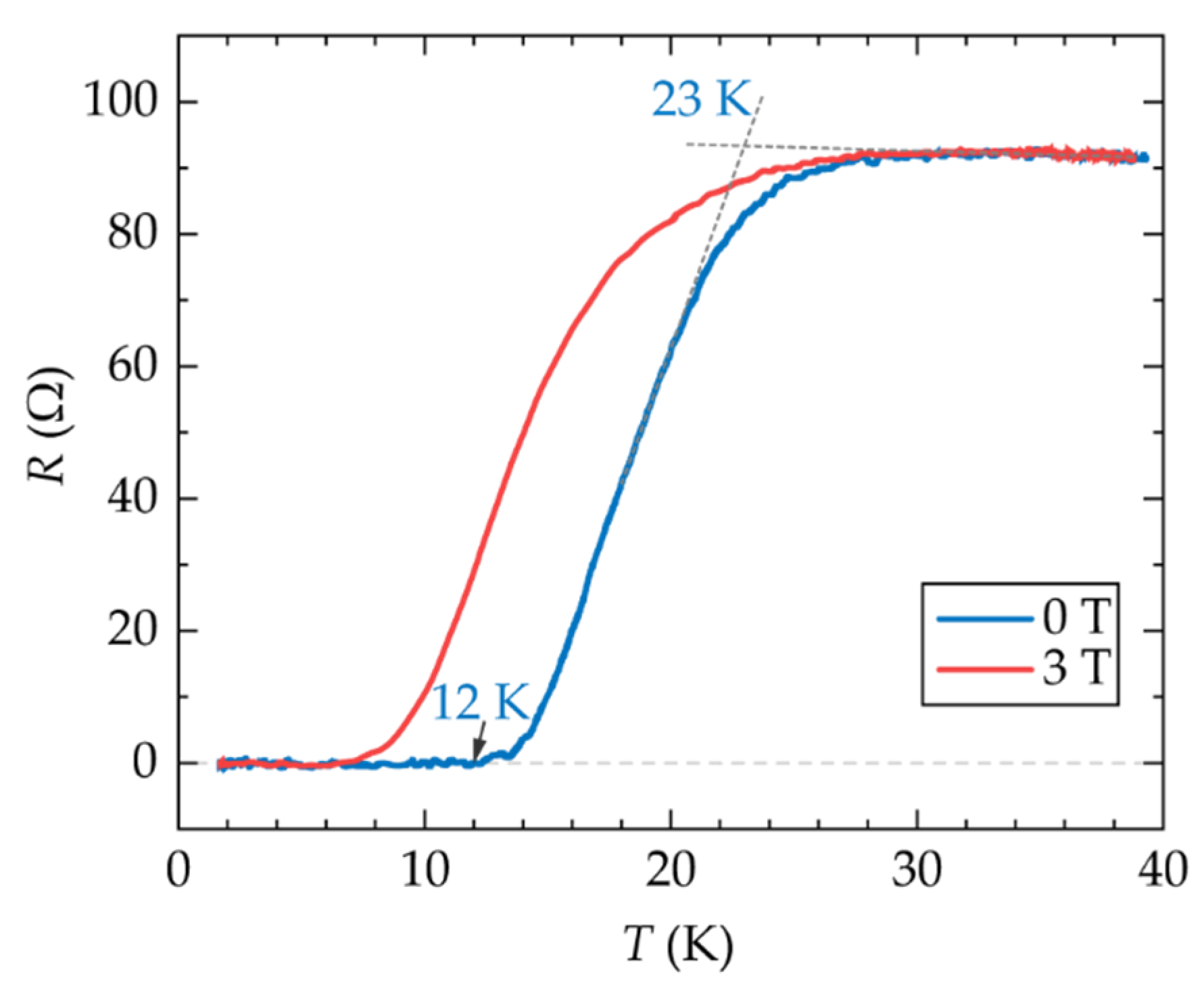
3.3. Transport Measurements

To confirm the above analysis and confirm the updated growth conditions, we grow a FeSe film with Se(180/1000) for 7.5 min (~1.5 layers), cap it with 10 layer FeTe as the protection, and carry out electric transport measurement at low temperatures. The results are displayed in Figure 4. A clear superconducting transition is observed and it is suppressed in a magnetic field. In zero fields, the onset transition temperature is ~23 K and the zero-resistance temperature is ~12 K, which is higher than that of the bulk FeSe. Also of note is that no post-growth annealing or other treatment is applied to this sample, which would certainly lead to nonsuperconducting or even insulating behaviors if it were grown in traditional ways [20,28]. Using the new method, the high-Tc superconductivity of monolayer FeSe can be directly obtained by adjusting the flux ratio.

4. Discussion

Combining careful flux control, RHEED observations, and transport measurements, we conclude that FeSe films can be grown more efficiently when a Se cracking source is used and direct stoichiometric growth is achievable. The cracker makes it possible to restrict the Se:Fe flux ratio close to 1. The lower Se flux could be beneficial in two ways—(1) it creates fewer Fe vacancies during the growth; and (2) it reduces the Se background pressure since the residual Se atmosphere can corrode the film after growth at lower temperatures [24]. Both will help to stabilize the superconducting phase in the as-grown film.
It is worth pointing out that the final Tc obtained by the transport measurements is not solely determined by the flux ratio in the growth, considering the sensitivity of the single-layer film and the complicated sample preparation process [29]. It is still challenging to reproduce the record onset Tc of ~40 K [30,31] in the ex situ macroscopic transport measurements and the results often vary among different samples in different studies [20,32,33,34]. Multiple aspects, including the substrate crystal quality, the substrate temperature, the uniformity of sample heating and flux distribution, the stability of the source flux, the growth conditions for capping layers, the chamber vacuum level during growth, etc., need to be carefully handled so as to improve the resulting superconductivity.
Nevertheless, this work clarifies that stoichiometry control in the growth process is the key to the superconductivity of FeSe films. Also, we have established a feasible workflow to optimize the growth conditions and simplified the procedures for preparing FeSe superconducting films. The ideas could be migrated to the MBE growth of other two-dimensional selenide/telluride materials [35,36].

Author Contributions

Conceptualization, C.L.; Data curation, K.Z. and H.W.; Formal analysis, K.Z. and C.L.; Funding acquisition, Y.Z. (Yunyi Zang), X.X., K.C. and K.H.; Investigation, K.Z., H.W., Y.Z. (Yuying Zhu), Y.Z. (Yunyi Zang), Y.F., B.T. and C.L.; Methodology, K.Z. and C.L.; Project administration, K.H. and C.L.; Resources, Y.Z. (Yuying Zhu), D.Z. and K.C.; Software, K.Z. and C.L.; Supervision, K.H. and C.L.; Visualization, K.Z., H.W. and C.L.; Writing—original draft, C.L.; Writing—review & editing, K.Z. and C.L. All authors have read and agreed to the published version of the manuscript.

Funding

This research was supported by the Beijing Natural Science Foundation (Grant No. 1222034) and the State Key Laboratory of High Performance Computing, National University of Defense Technology (Grant No. 2021101-27). K.C. acknowledges the funding from the National Natural Science Foundation of China (Grant No. 12074038 and No. 92165104).

Institutional Review Board Statement

Not applicable.

Informed Consent Statement

Not applicable.

Data Availability Statement

The data presented in this study are available on request from the corresponding authors.

Conflicts of Interest

The authors declare no conflict of interest.

References

  1. Wang, Q.-Y.; Li, Z.; Zhang, W.-H.; Zhang, Z.-C.; Zhang, J.-S.; Li, W.; Ding, H.; Ou, Y.-B.; Deng, P.; Chang, K.; et al. Interface-induced high-temperature superconductivity in single unit-cell FeSe films on SrTiO3. Chin. Phys. Lett. 2012, 29, 037402. [Google Scholar] [CrossRef] [Green Version]
  2. Faeth, B.D.; Yang, S.L.; Kawasaki, J.K.; Nelson, J.N.; Mishra, P.; Parzyck, C.T.; Li, C.; Schlom, D.G.; Shen, K.M. Incoherent Cooper pairing and pseudogap behavior in single-layer FeSe/SrTiO3. Phys. Rev. X 2021, 11, 021054. [Google Scholar] [CrossRef]
  3. Xu, Y.; Rong, H.; Wang, Q.; Wu, D.; Hu, Y.; Cai, Y.; Gao, Q.; Yan, H.; Li, C.; Yin, C.; et al. Spectroscopic evidence of superconductivity pairing at 83 K in single-layer FeSe/SrTiO3 films. Nat. Commun. 2021, 12, 2840. [Google Scholar] [CrossRef] [PubMed]
  4. Liu, D.; Zhang, W.; Mou, D.; He, J.; Ou, Y.B.; Wang, Q.Y.; Li, Z.; Wang, L.; Zhao, L.; He, S.; et al. Electronic origin of high-temperature superconductivity in single-layer FeSe superconductor. Nat. Commun. 2012, 3, 931. [Google Scholar] [CrossRef] [PubMed] [Green Version]
  5. Liu, X.; Liu, D.; Zhang, W.; He, J.; Zhao, L.; He, S.; Mou, D.; Li, F.; Tang, C.; Li, Z.; et al. Dichotomy of the electronic structure and superconductivity between single-layer and double-layer FeSe/SrTiO3 films. Nat. Commun. 2014, 5, 5047. [Google Scholar] [CrossRef] [Green Version]
  6. Pelliciari, J.; Karakuzu, S.; Song, Q.; Arpaia, R.; Nag, A.; Rossi, M.; Li, J.; Yu, T.; Chen, X.; Peng, R.; et al. Evolution of spin excitations from bulk to monolayer FeSe. Nat. Commun. 2021, 12, 3122. [Google Scholar] [CrossRef]
  7. Ge, Z.; Yan, C.; Zhang, H.; Agterberg, D.; Weinert, M.; Li, L. Evidence for d-wave superconductivity in single layer FeSe/SrTiO3 Probed by quasiparticle scattering off step edges. Nano Lett. 2019, 19, 2497–2502. [Google Scholar] [CrossRef] [PubMed] [Green Version]
  8. Liu, C.; Wang, J. Heterostructural one-unit-cell FeSe/SrTiO3: From high-temperature superconductivity to topological states. 2D Mater. 2020, 7, 022006. [Google Scholar] [CrossRef] [Green Version]
  9. Zhang, H.; Zhang, D.; Lu, X.; Liu, C.; Zhou, G.; Ma, X.; Wang, L.; Jiang, P.; Xue, Q.K.; Bao, X. Origin of charge transfer and enhanced electron-phonon coupling in single unit-cell FeSe films on SrTiO3. Nat. Commun. 2017, 8, 214. [Google Scholar] [CrossRef] [PubMed] [Green Version]
  10. Liu, C.; Day, R.P.; Li, F.; Roemer, R.L.; Zhdanovich, S.; Gorovikov, S.; Pedersen, T.M.; Jiang, J.; Lee, S.; Schneider, M.; et al. High-order replica bands in monolayer FeSe/SrTiO3 revealed by polarization-dependent photoemission spectroscopy. Nat. Commun. 2021, 12, 4573. [Google Scholar] [CrossRef] [PubMed]
  11. Lee, J.J.; Schmitt, F.T.; Moore, R.G.; Johnston, S.; Cui, Y.T.; Li, W.; Yi, M.; Liu, Z.K.; Hashimoto, M.; Zhang, Y.; et al. Interfacial mode coupling as the origin of the enhancement of Tc in FeSe films on SrTiO3. Nature 2014, 515, 245–248. [Google Scholar] [CrossRef] [PubMed]
  12. Feng, Z.; Yuan, J.; He, G.; Hu, W.; Lin, Z.; Li, D.; Jiang, X.; Huang, Y.; Ni, S.; Li, J.; et al. Tunable critical temperature for superconductivity in FeSe thin films by pulsed laser deposition. Sci. Rep. 2018, 8, 4039. [Google Scholar] [CrossRef] [PubMed]
  13. Obata, Y.; Karateev, I.A.; Pavlov, I.; Vasiliev, A.L.; Haindl, S. Challenges for pulsed laser deposition of FeSe thin films. Micromachines 2021, 12, 1224. [Google Scholar] [CrossRef] [PubMed]
  14. Li, Z.; Peng, J.P.; Zhang, H.M.; Zhang, W.H.; Ding, H.; Deng, P.; Chang, K.; Song, C.L.; Ji, S.H.; Wang, L.; et al. Molecular beam epitaxy growth and post-growth annealing of FeSe films on SrTiO3: A scanning tunneling microscopy study. J. Phys. Condens. Matter 2014, 26, 265002. [Google Scholar] [CrossRef]
  15. Liu, D.S.H.; Hilse, M.; Engel-Herbert, R. Sticking coefficients of selenium and tellurium. J. Vac. Sci. Technol. A 2021, 39, 023413. [Google Scholar] [CrossRef]
  16. Tan, S.; Zhang, Y.; Xia, M.; Ye, Z.; Chen, F.; Xie, X.; Peng, R.; Xu, D.; Fan, Q.; Xu, H.; et al. Interface-induced superconductivity and strain-dependent spin density waves in FeSe/SrTiO3 thin films. Nat. Mater. 2013, 12, 634–640. [Google Scholar] [CrossRef] [PubMed] [Green Version]
  17. Viswanathan, R.; Balasubramanian, R.; Darwin Albert Raj, D.; Sai Baba, M.; Lakshmi Narasimhan, T.S. Vaporization studies on elemental tellurium and selenium by Knudsen effusion mass spectrometry. J. Alloys Compd. 2014, 603, 75–85. [Google Scholar] [CrossRef]
  18. Zhao, W.; Chang, C.-Z.; Xi, X.; Mak, K.F.; Moodera, J.S. Vortex phase transitions in monolayer FeSe film on SrTiO3. 2D Mater. 2016, 3, 024006. [Google Scholar] [CrossRef]
  19. Huang, D.; Webb, T.A.; Song, C.L.; Chang, C.Z.; Moodera, J.S.; Kaxiras, E.; Hoffman, J.E. Dumbbell Defects in FeSe Films: A scanning tunneling microscopy and first-principles investigation. Nano Lett. 2016, 16, 4224–4229. [Google Scholar] [CrossRef] [PubMed] [Green Version]
  20. Liu, C.; Zou, K. Tuning stoichiometry and its impact on superconductivity of monolayer and multilayer FeSe on SrTiO3. Phys. Rev. B 2020, 101, 140502(R). [Google Scholar] [CrossRef] [Green Version]
  21. Yeh, K.-Y.; Chen, Y.-R.; Lo, T.-S.; Wu, P.M.; Wang, M.-J.; Chang-Liao, K.-S.; Wu, M.-K. Fe-vacancy-ordered Fe4Se5: The insulating parent phase of FeSe superconductor. Front. Phys. 2020, 8, 567054. [Google Scholar] [CrossRef]
  22. Chen, T.K.; Chang, C.C.; Chang, H.H.; Fang, A.H.; Wang, C.H.; Chao, W.H.; Tseng, C.M.; Lee, Y.C.; Wu, Y.R.; Wen, M.H.; et al. Fe-vacancy order and superconductivity in tetragonal beta-Fe1-xSe. Proc. Natl. Acad. Sci. USA 2014, 111, 63–68. [Google Scholar] [CrossRef] [PubMed] [Green Version]
  23. Liu, C.; Mao, J.; Ding, H.; Wu, R.; Tang, C.; Li, F.; He, K.; Li, W.; Song, C.-L.; Ma, X.-C.; et al. Extensive impurity-scattering study on the pairing symmetry of monolayer FeSe films on SrTiO3. Phys. Rev. B 2018, 97, 024502. [Google Scholar] [CrossRef] [Green Version]
  24. Yu, X.-Q.; Ren, M.-Q.; Zhang, Y.-M.; Fan, J.-Q.; Han, S.; Song, C.-L.; Ma, X.-C.; Xue, Q.-K. Stoichiometry and defect superstructures in epitaxial FeSe films on SrTiO3. Phys. Rev. Mater. 2020, 4, 051402(R). [Google Scholar] [CrossRef]
  25. Cammack, D.A.; Shahzad, K.; Marshall, T. Low-temperature growth of ZnSe by molecular beam epitaxy using cracked selenium. Appl. Phys. Lett. 1990, 56, 845–847. [Google Scholar] [CrossRef]
  26. Lee, J.J.; Schmitt, F.T.; Moore, R.G.; Vishik, I.M.; Ma, Y.; Shen, Z.X. Intrinsic ultrathin topological insulators grown via molecular beam epitaxy characterized by in-situ angle resolved photoemission spectroscopy. Appl. Phys. Lett. 2012, 101, 013118. [Google Scholar] [CrossRef] [Green Version]
  27. Zhang, M.-L.; Ge, J.-F.; Duan, M.-C.; Yao, G.; Liu, Z.-L.; Guan, D.-D.; Li, Y.-Y.; Qian, D.; Liu, C.-H.; Jia, J.-F. Molecular beam epitaxy growth of multilayer FeSe thin film on SrTiO3(001). Acta. Phys. Sin. 2016, 65, 127401. [Google Scholar] [CrossRef]
  28. Zhang, W.; Li, Z.; Li, F.; Zhang, H.; Peng, J.; Tang, C.; Wang, Q.; He, K.; Chen, X.; Wang, L.; et al. Interface charge doping effects on superconductivity of single-unit-cell FeSe films on SrTiO3 substrates. Phys. Rev. B 2014, 89, 060506(R). [Google Scholar] [CrossRef] [Green Version]
  29. Huang, D.; Hoffman, J.E. Monolayer FeSe on SrTiO3. Annu. Rev. Condens. Matter Phys. 2017, 8, 311–336. [Google Scholar] [CrossRef] [Green Version]
  30. Zhang, W.-H.; Sun, Y.; Zhang, J.-S.; Li, F.-S.; Guo, M.-H.; Zhao, Y.-F.; Zhang, H.-M.; Peng, J.-P.; Xing, Y.; Wang, H.-C.; et al. Direct observation of high-temperature superconductivity in one-unit-cell FeSe films. Chin. Phys. Lett. 2014, 31, 017401. [Google Scholar] [CrossRef] [Green Version]
  31. Sun, Y.; Zhang, W.; Xing, Y.; Li, F.; Zhao, Y.; Xia, Z.; Wang, L.; Ma, X.; Xue, Q.K.; Wang, J. High temperature superconducting FeSe films on SrTiO3 substrates. Sci. Rep. 2014, 4, 6040. [Google Scholar] [CrossRef] [PubMed]
  32. Zhao, W.; Li, M.; Chang, C.-Z.; Jiang, J.; Wu, L.; Liu, C.; Moodera, J.S.; Zhu, Y.; Chan, M.H.W. Direct imaging of electron transfer and its influence on superconducting pairing at FeSe/SrTiO3 interface. Sci. Adv. 2018, 4, eaao2682. [Google Scholar] [CrossRef] [PubMed] [Green Version]
  33. Yang, M.; Yan, C.; Ma, Y.; Li, L.; Cen, C. Light induced non-volatile switching of superconductivity in single layer FeSe on SrTiO3 substrate. Nat. Commun. 2019, 10, 85. [Google Scholar] [CrossRef]
  34. Pedersen, A.K.; Ichinokura, S.; Tanaka, T.; Shimizu, R.; Hitosugi, T.; Hirahara, T. Interfacial superconductivity in FeSe ultrathin films on SrTiO3 probed by in situ independently driven four-point-probe measurements. Phys. Rev. Lett. 2020, 124, 227002. [Google Scholar] [CrossRef]
  35. Wang, Z.; Zhou, T.; Jiang, T.; Sun, H.; Zang, Y.; Gong, Y.; Zhang, J.; Tong, M.; Xie, X.; Liu, Q.; et al. Dimensional crossover and topological nature of the thin films of a three-dimensional topological insulator by band gap engineering. Nano Lett. 2019, 19, 4627–4633. [Google Scholar] [CrossRef]
  36. Sun, H.; Jiang, T.; Zang, Y.; Zheng, X.; Gong, Y.; Yan, Y.; Xu, Z.; Liu, Y.; Fang, L.; Cheng, X.; et al. Broadband ultrafast photovoltaic detectors based on large-scale topological insulator Sb2Te3/STO heterostructures. Nanoscale 2017, 9, 9325–9332. [Google Scholar] [CrossRef] [PubMed]
Figure 1. Selenium flux measured by a QCM as a function of the reservoir temperature while keeping the cracking zone at 1000 °C. Red and blue data points are from two sets of measurements a month apart. The yellow band is a guide for the eye. The Fe flux is fixed in this study, indicated by the green dashed line. The flux unit is converted to number of layers per minute, considering the density of the element in the tetragonal FeSe. The inset is a schematic of the Se cracker.
Crystals 12 00853 g001
Figure 2. RHEED images of (a) treated STO substrate, (b) FeSe film grown for 5 min with Se(185/1000), and (c) FeSe film grown for 5 min with Se(200/600). The additional spots marked by the arrows in (c) indicate the formation of Fe islands.
Crystals 12 00853 g002
Figure 3. RHEED characterization on the growth of FeSe for different Se fluxes. (ad) RHEED images of monolayer FeSe grown with various Se flux as labeled on the figures. (eh) Real-time RHEED intensity of (00), (01), and (02) diffractions during growth, corresponding to the samples in (ad). The integrated areas are marked on (a) and are the same for (bd). The red dashed lines in (eh) indicate the time at which the first layer FeSe is completed.
Crystals 12 00853 g003
Figure 4. Resistance-temperature curves of a 1.5-layer FeSe film grown with Se(180,1000) in the magnetic field of 0 T and 3 T (B//c). The film is capped with 10 layer FeTe.
Crystals 12 00853 g004
Publisher’s Note: MDPI stays neutral with regard to jurisdictional claims in published maps and institutional affiliations.

