1. Introduction
Transition metal nitrides are robust materials with large mechanical hardness, excellent corrosion- and wear-resistance, and thermal stability. Titanium nitride (TiN), for example, is a prominent transition metal nitride whose properties include high hardness (Vickers Hardness: 18–21 GPa), low resistivity (~25 μΩ·cm), and chemical inertness [
1]. TiN has also been reported as a thermally-stable plasmonic material, demonstrating plasmonic response at wavelengths larger than 500 nm for temperatures as high as 900 °C [
2]. Interestingly, other transition metal nitrides such as iron nitrides may exhibit even larger magnetizations and improved corrosion- and wear-resistance compared to pure Fe [
3,
4]. Due to their excellent mechanical and physical properties, numerous nitride-based materials have been used as super-hard, decorative, and biocompatible coatings as well as CMOS-compatible conductive diffusion barriers for integrated circuit interconnects [
1]. Transition metal nitrides continue to generate significant research interests as the materials enter the nanoscale. For example, nanostructured nitride coatings have been reported to have tunable mechanical properties [
5], tailorable plasmonic properties in TiN nanoparticles [
6], hyperbolic optical properties in TiN–Au/TaN–Au multilayers [
7], and enhanced the ion radiation tolerance properties in nanostructured TiN, AlN, ZrN, and their multilayer coatings [
8,
9,
10]. However, most of these nanostructures have been focused on single layers or multilayer structures with very limited reports on vertical nanostructures [
11,
12].
To this end, two-phase vertically aligned nanocomposites (VANs) have emerged as an attractive vertical framework to introduce additional interface-driven functionalities and further enhance the anisotropic nature of nitride material systems. These VAN structures possess an array of nanopillars in a matrix phase, both epitaxially grown on substrates. The advantages of VANs compared to other types of nanocomposites include a high density of vertical heterointerfaces, lateral and vertical strain control, coupling effects, and self-assembled nanostructures [
13]. Several nitride-based VANs with fascinating properties have recently been demonstrated such as highly anisotropic reflectance and nonlinear optical properties in TaN–Au and enhanced optical sensing in TiN–Au hybrid metamaterials [
11,
12]. However, the coupling of the functionalities in nitride-based VANs has mostly focused on the mechanical, plasmonic, and optical properties with very limited reports on magnetic structure integration [
14]. Furthermore, despite the success of the integration of oxide–oxide and oxide–metal VANs on Si [
15,
16,
17,
18,
19,
20], there have been limited demonstrations of nitride-based VANs integrated on Si.
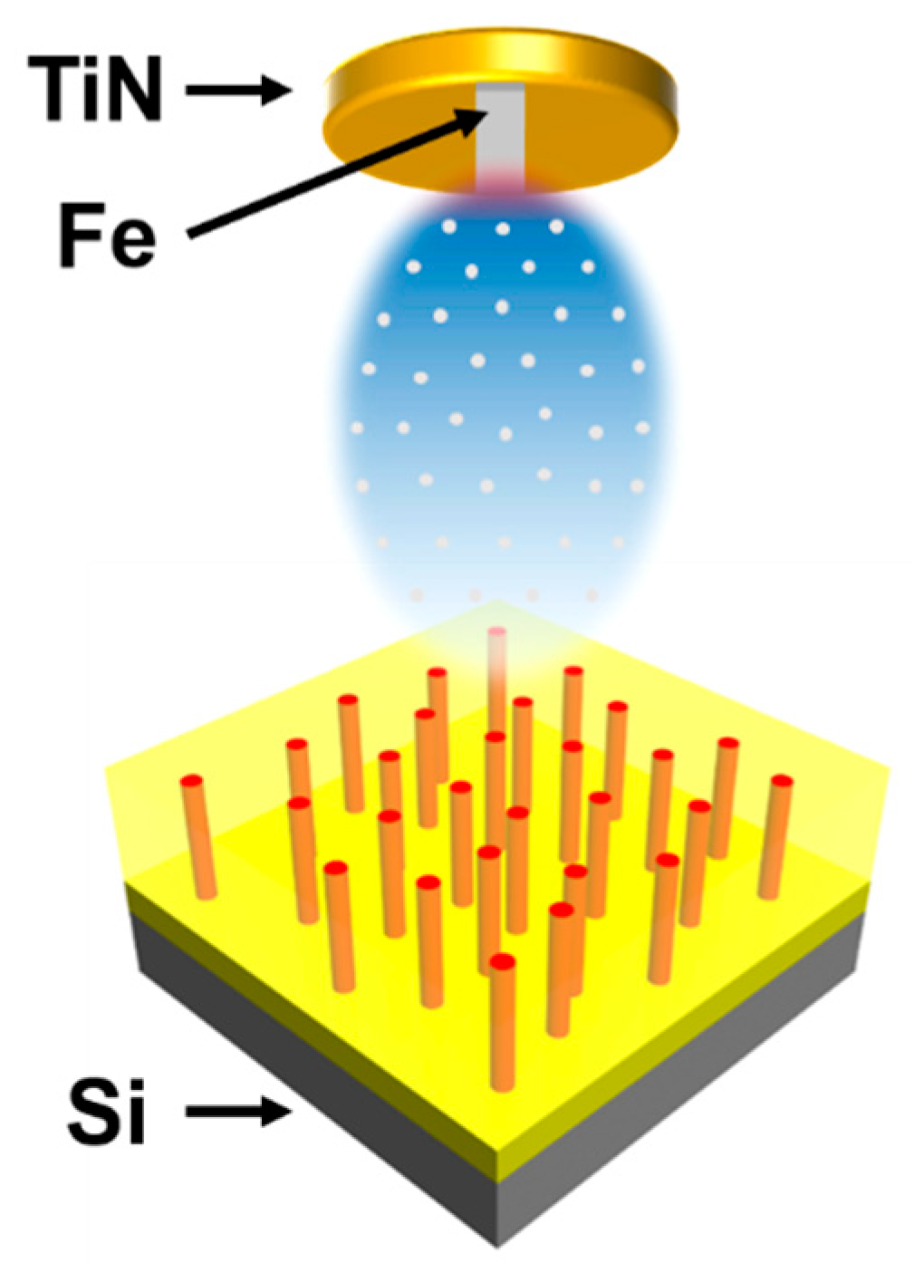
In this work, we report for the first time a TiN–Fe VAN thin film fabricated with pulsed laser deposition on conductive (1–10 Ω-cm) Si substrates. TiN was chosen as the matrix nitride considering its epitaxial growth of TiN on Si through the domain matching epitaxy (i.e., four TiN (200) lattices matching well with three Si (200) lattices) [
5,
21]. Fe was selected as the secondary phase considering its magnetic properties and potential to grow epitaxially with TiN and Si. A schematic of the target geometry and proposed VAN system with Fe nanopillars in a TiN matrix is shown in
Figure 1. From a functional standpoint, TiN serves as the matrix nitride for its ability to act as a diffusion barrier and for its reported plasmonic properties, while Fe introduces ferromagnetic properties. From an epitaxial growth standpoint, Si (100) substrates were chosen for the deposited TiN (a
TiN = 4.24 Å) to achieve domain matching epitaxy with Si (a
Si = 5.43 Å). For instance, four TiN (200) lattices (8.48 Å) matched well with three Si (200) lattices (8.15 Å) [
5,
21]. Similarly, the interplanar distance of Fe (110) matched fairly well to that of TiN (200) (2.03 Å and 2.12 Å, respectively). Given that the basic conditions for in-plane and out-of-plane epitaxy between Si, TiN, and Fe are met, a VAN structure can be reasonably predicted. A detailed microstructural analysis coupled with the physical property measurements including optical and magnetic properties was conducted to explore their potential in tunable magneto-optical anisotropy and integration with Si.
2. Methods
Thin films were produced by pulsed laser deposition (PLD) of a pseudo-composite TiN–Fe target (prepared by attaching a 4 mm-wide strip of Fe onto a pure, commercially-obtained TiN target) with a KrF excimer laser (λ = 248 nm). Prior to deposition, 1 cm2 pieces of conductive (1–10 Ω) Si (001) substrates were cleaned ultrasonically with acetone and methanol, followed by an HF etch (49 wt.%) for 40 s. Upon cleaning, the substrates were loaded into the PLD chamber and pumped to high vacuum (<1.0 10−6 mTorr). The substrates were then heated to 700 °C. During deposition, the TiN–Fe target was continuously rotated and laser ablated at a frequency of 5 Hz in high vacuum. The track, or path of laser ablation on the target, had a diameter of 1.5 cm, resulting in the nominal target composition of TiN0.9:Fe0.1. The pure TiN buffer layer was deposited under the same conditions, but without the Fe strip attached. After deposition, the samples were cooled to room temperature in high vacuum. The crystallinity, phases, and nanostructure of the deposited thin films were characterized using X-ray diffraction (XRD, Panalytical Empyrean, Westborough, MA, USA), transmission electron microscopy (TEM, Thermo Fisher Scientific (FEI) Talos F200X, Hillsboro, OR, USA), scanning transmission electron microscopy (STEM), and electron-dispersive X-ray spectroscopy (EDS). In-plane and out-of-plane magnetic properties were measured with a superconducting quantum interference device (SQUID, Quantum Design MPMS-3, San Diego, CA, USA) in a vibrating sample mode. Reflectance spectra were obtained with a spectroscopic ellipsometer (J.A. Woollam RC2, Lincoln, NE, USA) with variable incident angles of 30–70°. The optical permittivity was extracted from the measured ellipsometric data, Psi () and Delta () at variable angles (55°, 65°, and 75°) by choosing appropriate models and oscillators on CompleteEASE software.
3. Results and Discussion
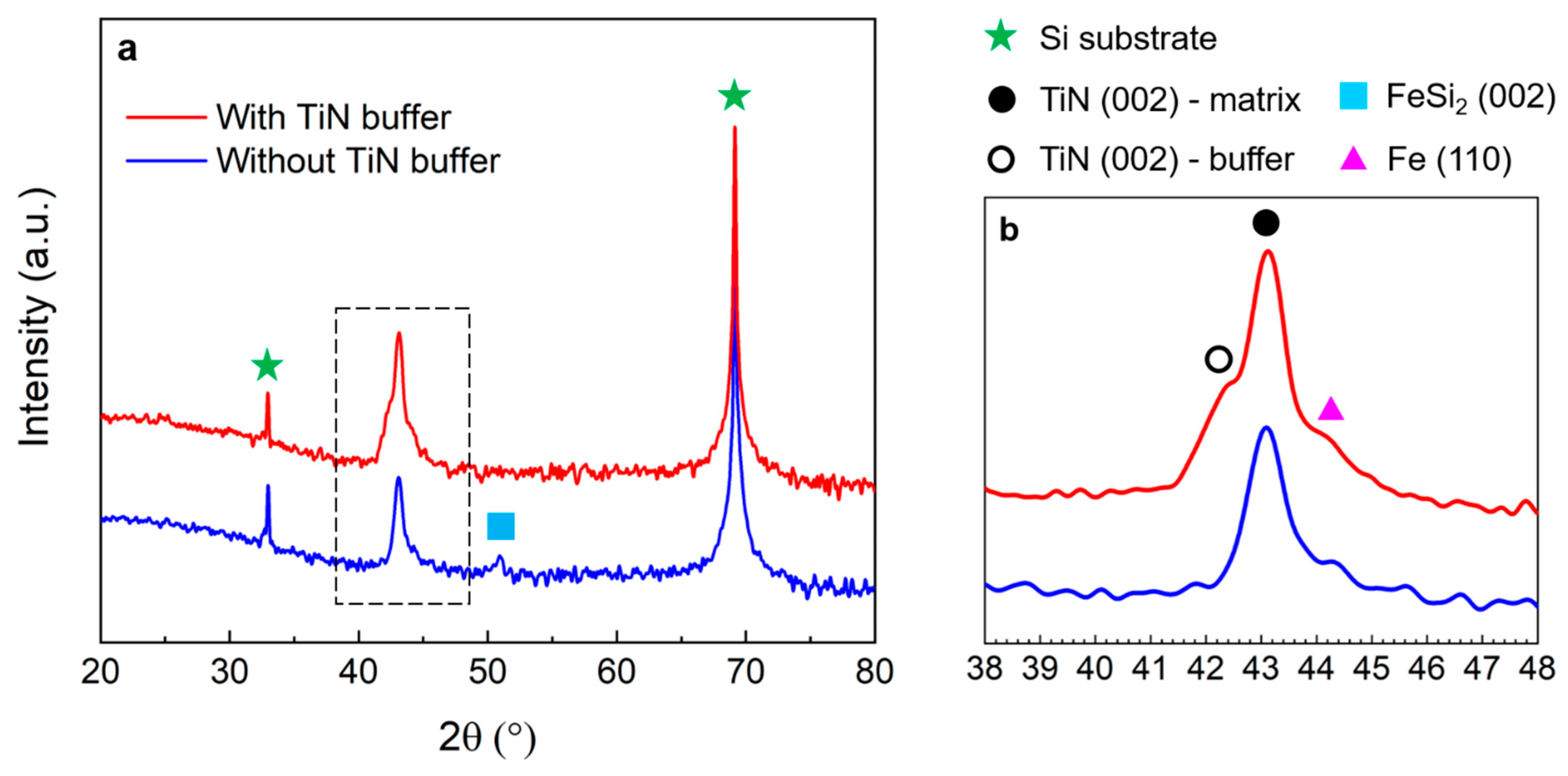
To discern the crystallinity and identify the phases present within the samples, the deposited thin films were initially characterized using X-ray diffraction (XRD). The Fe and TiN phases were determined by matching the measured X-ray diffractograms to crystallographic data. The XRD
θ–2θ patterns of the films grown with and without a TiN buffer on Si are compared in
Figure 2. The film grown without a buffer showed a prominent diffraction peak for TiN (002) as well as smaller Fe (110) and FeSi
2 (002) peaks. The presence of TiN (002) indicates that the nitride matrix grew epitaxially, albeit with a slightly smaller lattice parameter of 4.19 Å compared to the bulk value of 4.24 Å, corresponding to a strain of about −1.2%. Furthermore, the Fe (110) peak, seen more clearly in the local area
θ–2θ pattern of
Figure 2b confirms the nanocomposite nature of the film. However, evidence of a FeSi
2 (002) phase suggests that some of the deposited Fe diffused into the Si substrate, which is reasonable considering the high diffusivity of Fe in Si at the deposition temperature (
D ≈ 3 × 10
−7 cm
2/s at 700 °C) [
22]. Apart from a few niche applications, this diffusion is typically undesired as it severely deteriorates the electrical properties and reliability in electrical devices.
To prevent this type of diffusion and promote the growth of a crystalline iron nitride phase, a second sample was grown with a pure TiN buffer layer deposited before the nanocomposite film. The θ–2θ pattern of this sample showed two pronounced TiN (002) peaks and a small Fe (110) shoulder peak. Moreover, no FeSi2 diffraction peaks were observed for this sample, further validating the crucial role of the buffer layer. The TiN (002) peak centered around 42.5° can be attributed to the buffer layer for two main reasons. First, the peak position suggests that there is minimal strain (<0.2%) in this layer, which is in accordance with the domain matching epitaxy paradigm of TiN (002) on the Si (001) substrates. Second, this peak intensity was relatively lower than the other TiN (002) peak centered at 43.1° for the nanocomposite matrix, which is reasonable considering the buffer layer thickness should be about one-third the thickness of the nanocomposite film. It is interesting to note that the crystallinity of the nanocomposite films was fairly independent of the TiN buffer layer. Specifically, the TiN (002) and Fe (110) peaks for each of the VAN films remained at roughly the same value of 2θ, regardless of whether the VAN was grown directly on the Si substrate or on a TiN buffer. The XRD analysis of the samples highlights the importance of the TiN buffer layer in preventing the diffusion of Fe into the Si substrate as well as the crystallinity of the TiN and Fe phases in the nanocomposite layer.
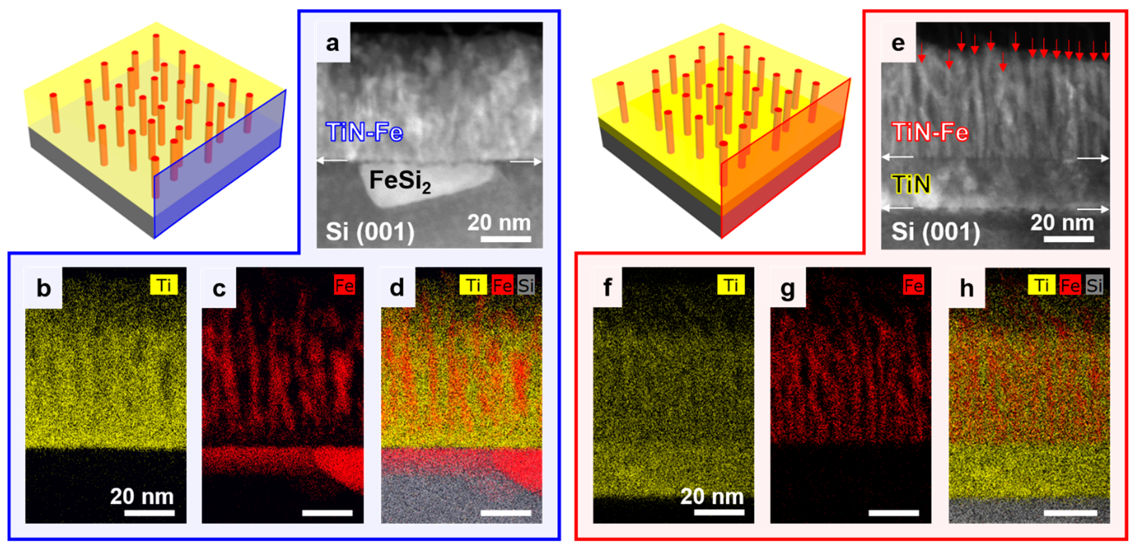
The nanostructure of the TiN–Fe thin films grown without and with a TiN buffer is presented in
Figure 3. Representative schematics for each sample are shown on the left side of the figure. To verify the VAN structure and distribution of elements throughout the films, scanning transmission electron microscopy (STEM) under high-angle annular dark-field (HAADF) mode coupled with electron-dispersive X-ray spectroscopy (EDS) was used. A STEM image of the TiN–Fe film grown directly on the Si substrate is presented in
Figure 3a, indicating a film thickness of about 60 nm. This image also clearly shows that Fe diffused into Si to form FeSi
2 just below the film–substrate interface, which is in agreement with the previously obtained XRD data. Elemental mappings of Ti and Fe were obtained and are displayed in
Figure 3b,c, respectively, and a composite mapping including the Ti, Fe, and Si elements is shown in
Figure 3d. These elements were selected due to their significant content in the film and reliable detection through EDS. Nitrogen was not included in the elemental maps as it falls below the typical detection limit for EDS and would not be reliably quantifiable. Since the enthalpy of the formation of titanium nitride is much lower than that of iron nitride and silicon nitride, it is reasonable to assume that the distribution of nitrogen closely follows that of titanium. The Fe elemental map, in particular, emphasizes the Fe nanopillars within the film, which have diameters of about 4–5 nm.
A STEM image of the TiN–Fe film grown on the TiN buffer layer is shown in
Figure 3e. The Fe nanopillars, whose positions are indicated by the red arrows, are more evident in the STEM image of this film compared to that of the film grown directly on the Si substrate. The TiN buffer layer was about 20 nm thick while the VAN layer was 60 nm, having essentially the same thickness as the TiN–Fe film grown directly on the Si substrate. The ratio of the VAN layer thickness to the buffer layer thickness agreed well with the ratio of pulses used for the deposition of the VAN layer and buffer layer (3:1). For the TiN–Fe film grown on the TiN buffer, elemental mappings of Ti and Fe are shown in
Figure 3f,g, respectively, and a composite of the Ti, Fe, and Si maps is shown in
Figure 3h. Furthermore, elemental maps of the sample grown with a TiN buffer confirm a complete lack of Fe in the buffer layer and substrate, which suggests that the TiN layer indeed acts as a diffusion barrier. Two additional observations can be made regarding the TiN–Fe in both samples. First, the pillar morphologies appeared to be similar. However, the sample grown with the pure TiN buffer provided better epitaxial conditions for Fe considering a smaller lattice mismatch between the Fe and TiN compared to Fe and Si, and the very limited diffusion of Fe in Si, as evidenced previously in the XRD results. Second, although Fe may not form idealized pillars as presented in the schematics, the elemental maps of Fe emphasize its preferred columnar growth with ultra-fine structures. Regarding this point, some overlap in the Ti and Fe distributions in the elemental maps was observed. This can be attributed to the very fine Fe nanopillar structures. Since the electron beam interacts through a sample thickness of ~10 nm or more, it is likely for small portions of the TiN matrix to be in front of or behind the Fe nanopillars, causing some Ti signal to appear in the Fe-rich regions. It is unlikely that phases such as TiFe or FeN formed due to those having much greater enthalpies of formation compared to that of TiN. Furthermore, there is no evidence of the former two phases from the XRD results, so it is reasonably assumed that the TiN and Fe phases were well separated.
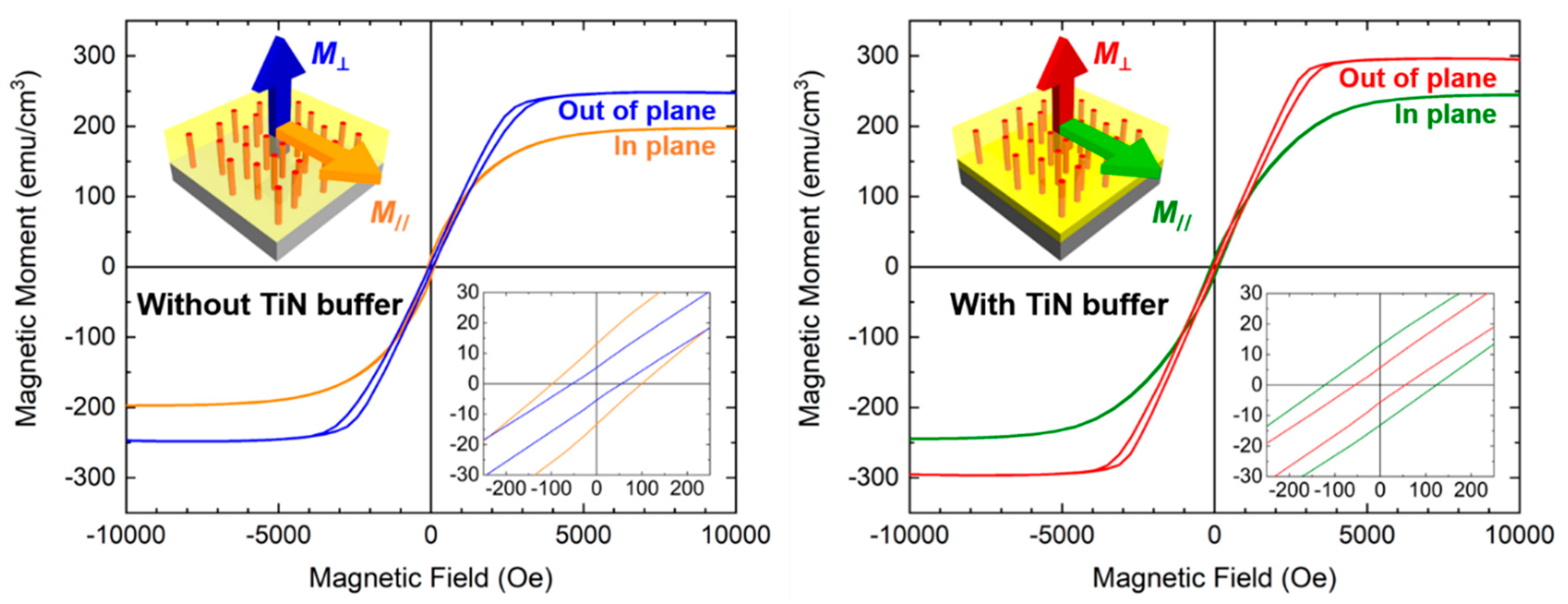
Having determined the composition and nanostructure of the TiN–Fe thin films, the magnetic properties of the samples were subsequently explored. In-plane and out-of-plane
M–
H responses were measured at room temperature for the two samples. The results, presented in
Figure 4, indicate that both samples exhibited similar ferromagnetic properties such as large magnetization saturation
MS, low coercivity
HC, and perpendicular magnetic anisotropy. Large magnetization saturations and low coercivities are characteristic of Fe—a soft ferromagnetic material in its bulk form. Here, the magnetic anisotropy is largely attributed to the shape anisotropy of the Fe pillars, which have an aspect ratio (i.e., height/diameter) significantly greater than one. These highly anisotropic nanostructures are formed by a self-assembly process during deposition, in which the two different phases (e.g., TiN and Fe) form columnar domains with a preferred out-of-plane growth orientation. Magnetic anisotropy was evident from the
M–
H data in that the out-of-plane measurement revealed an easy axis of magnetization (i.e., parallel to the alignment of Fe nanopillars), while the in-plane measurement showed a hard axis. The similar magnetic behavior of both films can be explained by their comparable crystallinity and morphology, as evidenced by the XRD and EDS analysis. The results obtained from the XRD and EDS help explain the inherent magnetic anisotropy as well as the larger saturation magnetization for the sample grown with the TiN buffer layer. Previous reports on Fe-doped TiN materials showed similar ferromagnetic properties and other properties compared to the TiN–Fe VANs presented in this study. For example, in one such work, the Fe-doped TiN nanocrystals prepared by calcinating titanic acid demonstrated ferromagnetism and unique microwave absorption properties [
23]. In another two studies, the Fe-doped TiN thin films were deposited by magnetron sputtering and exhibited low electrical resistivity and varying magnetoresistance, depending on the concentration of Fe [
24,
25]. Overall, the magnetization measurements of the thin films are good indicators of anisotropic and soft ferromagnetic behavior, which are often used in device components such as magnetic read heads for memory storage or free (i.e., easily switchable) layers for magnetic tunnel junctions.
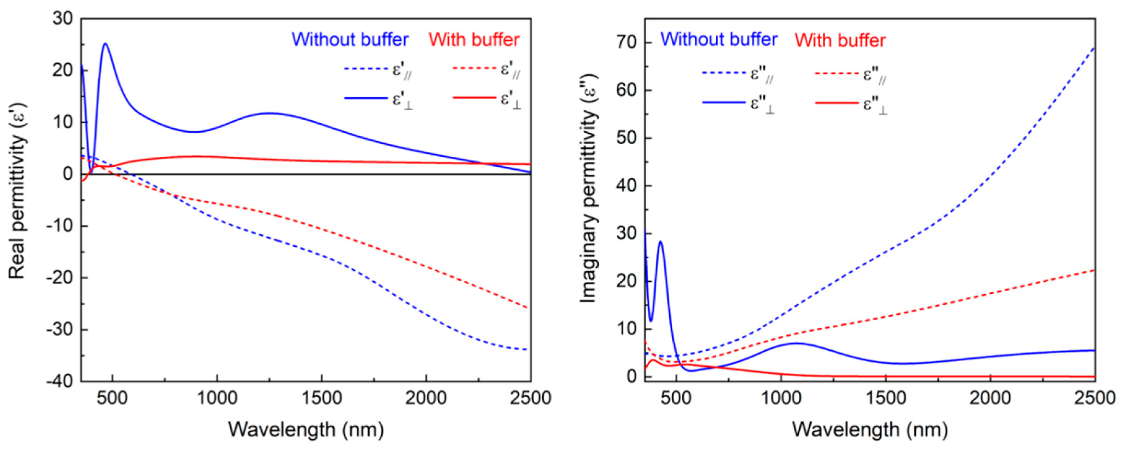
Based on recent reports of optical properties such as plasmonic response in pure TiN and TiN-based VAN thin films, the optical properties of the TiN–Fe thin films integrated on Si were also investigated in this study. Due to the anisotropic structure of the TiN–Fe films, in-plane and out-of-plane real and imaginary permittivity values of the TiN–Fe VANs, plotted in
Figure 5, were retrieved using a uniaxial anisotropy model due to the anisotropic morphology of the VAN films. For both films, the in-plane permittivity was clearly different from the out-of-plane permittivity values, confirming that the anisotropic nature of the TiN–Fe films also extends to the optical domain. Moreover, the in-plane real permittivity component (
) of both the TiN–Fe films showed a metallic response (i.e., negative permittivity values in the visible to near-infrared (vis-NIR) wavelength region), which can be explained by the metallic TiN matrix. In fact, the real (
) and imaginary (
) in-plane permittivity for both the TiN–Fe films exhibited similar trends compared to previous studies on pure TiN films grown on various substrates including Si [
26]. On the other hand, the real out-of-plane permittivity components (
) for both the TiN–Fe films remained positive throughout the vis-NIR region, which is consistent with the previous study of the BTO-Fe VAN film where the positive
was maintained despite the ultra-fine conductive Fe nanopillars [
27]. Moreover, the higher positive value for the TiN–Fe film grown without the TiN buffer indicates more dielectric characteristics along the out-of-plane direction, which may be caused by the poorer film growth quality and the large quantity of defects that may restrict the light propagation along the z-direction. Therefore, the TiN–Fe VAN film demonstrated Type II hyperbolic dispersion in the vis-NIR wavelength region [
28].
To validate that the calculated permittivity values of the TiN–Fe films were indeed meaningful, the same model was used to simulate the reflectance spectra at various angles. The simulated reflectance spectra were then compared to the experimentally-obtained angular-dependent reflectance (R%) measurements performed at various incident angles (e.g., 30°, 40°, 50°, 60°, and 70°). The simulated and measured data, shown in
Figure S1 in Supplementary Materials, were mostly similar. In general, the measured and simulated R% spectra for both films exhibited good agreement in the 400–800 nm visible wavelength region. The minor discrepancy between the experimented and simulated R% data for the TiN–Fe film grown on buffered TiN at a longer wavelength (800–2500 nm) can be attributed to the relatively large roughness at the surface and interface areas as well as the simplified biaxial model used in data fitting and simulation.
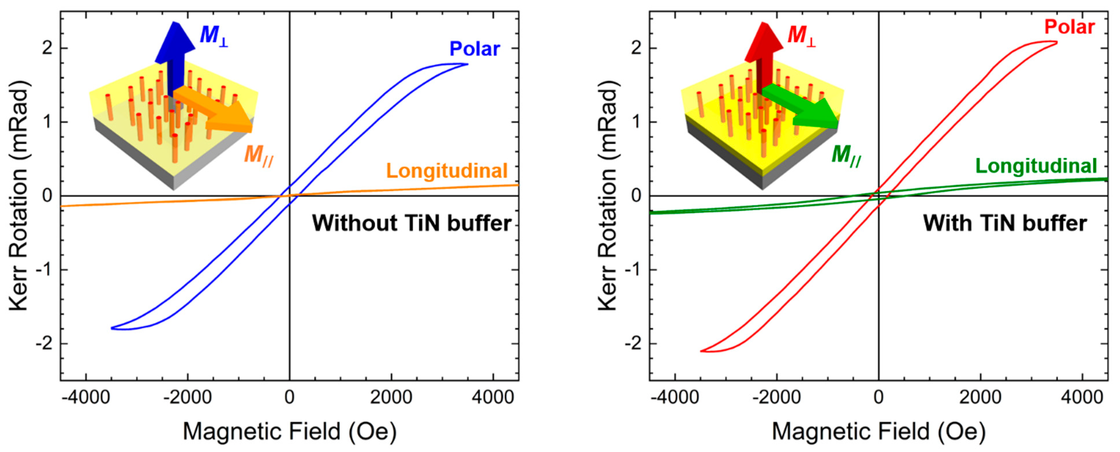
Considering the plasmonic properties of TiN, the ferromagnetic properties of Fe, and the overall optical and magnetic anisotropy, the TiN–Fe nanocomposite films were further characterized to explore the potential magneto-optical coupling via magneto-optical Kerr effect (MOKE) measurements. Polar and longitudinal MOKE measurements for both samples were obtained at room temperature, as shown in
Figure 6. In the polar MOKE measurement, the magnetic field was applied perpendicular to the substrate surface while in the longitudinal MOKE, the magnetic field was parallel to the substrate surface. Magnetic field-induced changes in the polarization of incident light were then recorded as a Kerr rotation. Data from these measurements performed on both the TiN–Fe films provide evidence that the samples indeed showed obvious MOKE responses. Differences between the polar and longitudinal MOKE results are attributed to the highly anisotropic nature of the TiN–Fe thin films and corroborate the magnetic anisotropy. Specifically, a significantly greater degree of Kerr rotation was obtained for the samples measured in polar MOKE compared to longitudinal MOKE. This can be explained by the magneto-optical coupling occurring predominantly along the vertical TiN–Fe interfaces as well as the preferred (“easy”) axis of magnetization being parallel to the Fe nanopillars. Slight differences between the TiN–Fe films grown with and without a TiN buffer are mainly the result of changes in morphology. It is also interesting to note that the MOKE in these TiN–Fe films was considerably stronger than that of the recently demonstrated VAN systems such as NiO–TiN, NiO–TiN–Au, and La
0.
5Sr
0.
5FeO
3–Au–Fe [
14,
29,
30], possibly due to the larger ferromagnetic response in Fe (compared to NiO) or the higher density of magneto-optical coupling interfaces between the TiN and Fe nanopillars.
Overall, the demonstration of the TiN–Fe VANs integrated on Si is of great importance for several reasons. The ability to fabricate epitaxial nitride-metal VANs on Si presents a low-cost and CMOS-compatible alternative to typical VAN depositions on single-crystal oxide substrates such as MgO. Furthermore, this nitride and ferromagnetic metal VAN platform can be extended to various other combinations of AlN, ZrN, Ni, Co, and others to form entirely new nanostructured systems whose properties are yet to be explored. Additional work can be directed toward creating more uniform, templated, or patterned VANs, especially as these materials enter the realm of devices.


 ,
, 


