Article

Narrow Gap Welding of X80 Steel Using Laser-CMT Hybrid Welding with Misaligned Laser and Arc

1
School of Materials Science and Engineering, Tianjin University, Tianjin 300350, China
2
PetroChina International Welding Technology Training Center, Daqing 163712, China
3
Central Research Institute of Building and Construction Co., Ltd., MCC Group, Beijing 100088, China
4
Department of Mechanical Engineering, Faculty of Engineering, Bayero University, Kano 3011, Nigeria
*
Author to whom correspondence should be addressed.
Crystals 2022, 12(6), 832; https://doi.org/10.3390/cryst12060832
Submission received: 9 May 2022 / Revised: 5 June 2022 / Accepted: 7 June 2022 / Published: 12 June 2022
(This article belongs to the Special Issue Determinants of Welding Performance of Crystalline Materials)

Abstract

:
The feasibility of using laser-cold metal transfer (CMT) misaligned hybrid welding to join an X80 line-pipe steel in a narrow gap configuration was investigated. The laser beam interacted with the sidewall and its bottom at a small angle, while the CMT arc acted on the backside of the laser beam. The influence of the distance parameter between the laser spot and the tip of the welding wire on the formation and defects of the filled weld were investigated. Narrow gap bevel welds were performed, and the joints were tensile and had a satisfactory Charpy impact score. The tensile fracture is located in the base metal, and the impact fracture is a ductile fracture. Under this condition, the heat input could be efficiently reduced, preventing the formation of defects such as lack of fusion and reducing the number of pores. Additionally, welds with a narrow heat affect zone (HAZ) could be obtained. The results reveal that the hybrid process, as a low-heat input method, is suitable for narrow gap welding.

1. Introduction

Welding technology is often used for processing and connection in the manufacturing of thick metal plates [1,2,3,4,5]. Thick plates are difficult to penetrate through, and multi-layer multi-pass welding is usually employed to join thick metal plates. The traditional welding process requires a wide groove on the thick plate [6,7,8,9,10], and the welding of the wide groove has the disadvantages of a long time-cutting process, requires a large amount of metal filling, has large residual stress and a low welding efficiency. The application of narrow gap welding in the manufacturing of thick plate structures has several advantages, such as a reduction in the use of filler metals and low stress development, which improve the welding efficiency [11,12]. However, the narrow gap poses certain challenges to the currently available welding methods, such as the restriction of the welding angle by the narrowness of the gap [13]. Li et al. [14] used arc oscillating GTAW as the heat source in narrow gap welding, and indicated that the fusion defects can be reduced. However, the size of the heat affect zone (HAZ) increased. As an alternative solution, Sokolov et al. [15] employed a 30k IPG fiber laser to conduct narrow gap welding of 30 mm-thick S355 steel plates, and encouraging results were obtained. However, the method requires the use of plates that are manufactured with high precision. Laser-arc hybrid welding [16,17,18,19,20] integrates the advantages of both laser and arc. Compared with arc welding, the phenomenon that the arc may climb upward to the sidewall of groove can be restricted by the laser, i.e., the stiffness of the arc can be improved by the laser [16]. The deposition efficiency is also increased. Compared with laser welding, the tolerance requirement is reduced [17]. However, the heat input in the existing laser-arc hybrid welding methods for narrow gap welding is still too high, leading to an increased HAZ size and reduced joint quality [21]. Therefore, it is crucial to develop a new strategy to control the heat input in narrow gap welding, thereby reducing the HAZ size and achieving defect-free welding.
Laser-cold metal transfer (laser-CMT) hybrid welding is a relatively new welding method with low heat input. It is reported that laser-CMT welding could increase the stability of the welding process, leading to good weld formation [22,23]. However, there is a scarcity of published literature using laser-CMT welding to join thick metal plates in narrow gap configuration. This paper proposes novel laser-CMT hybrid welding with a misaligned laser and arc, which realizes a narrow HAZ and a defect-free welded joint of a thick X-80 pipeline steel in the form of narrow gap configuration. In this method, the sidewall of the groove was melted by the laser, and its bottom was melted by the arc. The melting pool characteristics and weld formation as a function of the laser and arc interactions were investigated.

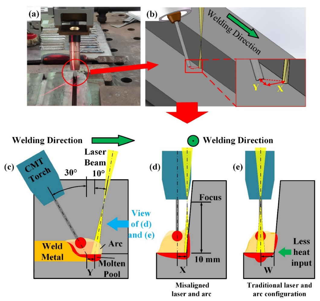
2. Experimental Procedure

The X80 line-pipe steel was used as the base material. The ER80S Lincoln Electric company welding wire with a diameter of 1.2 mm was selected as the welding wire. The compositions of the base material and welding wire are given in Table 1. Figure 1a shows the schematic diagram of the sidewall fusion experiment. One plate whose edge is machined at an angle of 85° was placed on a flat plate to simulate the angle of the sidewall. Figure 1b shows the weld groove in the narrow gap welding. The gap root face has a thickness of 4 mm, a sidewall angle of 5°, and a 6.5 mm bottom width.
The laser-CMT hybrid welding system was equipped with an LSJR-FL10000 fiber laser with a maximum power of 10,000 W and a CMT 4000 Adv welding machine, as shown in Figure 2a. The welding method proposed in this study is shown in Figure 2b. The laser was set to be in front of the wire (arc) during the welding, and the laser-wire distance (dL-W) in the welding direction is marked as “Y”. The laser and the arc were misaligned with a distance of “X”, as shown in Figure 2b,d. The laser irradiated the sidewall and bottom of the sidewall at a small angle. Part of the laser energy was irradiated on the sidewall, while the CMT acted on the backside of the laser. The relative position of the laser and wire in traditional laser-arc hybrid welding are illustrated in Figure 2e. The laser and the arc were set to be in the same straight line parallel to the welding direction. The distance between the laser and the sidewall was set as W. During welding, the laser parameters were as follows: a laser power of 1000 W and defocus distance of 10 mm. The CMT parameters were as follows: a wire feed rate of 5.5 m/min, welding current of 180 A, and speed of 0.6 m/min. Metallographic samples were cut from the cross-section of the weld, ground, polished and etched with 4% nitrate alcohol. The joint macrostructures were observed with a Zeiss ultra-depth-of-field microscope. According to the standard SY/T 0452-2012, tensile and impact samples were made to test the mechanical properties of the weld (Figure 3).

3. Results and Discussion

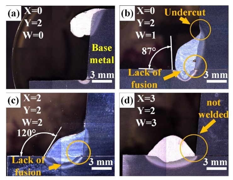
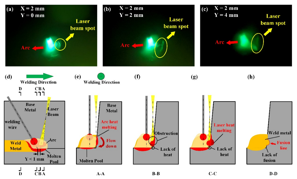
3.1. Sidewall Fusion Experiments

Figure 4 shows the macroscopic morphology of the weld under different laser and wire distances in a traditional laser-arc configuration. As shown in Figure 4a, when the distance between the laser and the groove sidewall was 0 mm, the arc was generated at the apex of the sidewall due to the insufficient distance from the sidewall to the laser. When W was 1 mm, an undercut defect appeared at the top of the weld, and a lack of fusion appeared at the bottom end of the sidewall, as shown in Figure 4b. This is mainly due to the fact that the arc was located on the sidewall of the groove but not on the bottom of the gap during welding, resulting in the formation of undercuts. In addition, on the left side of the weld, when the forming angle was less than 90°, it was not able to fill the next weld in the multi-pass welding. Figure 4c presents the weld when the distance W was 2 mm. The weld was well-formed; and no undercut appeared. The forming angle at the lower weld toe also improved. However, a lack-of-fusion defect was observed at the bottom end of the sidewall, indicating that the heat input was small and the base metal was not fully melted. In Figure 4d, it can be seen that the sidewall did not melt at all.
Figure 5 shows the macroscopic morphology of the weld under a misaligned laser-arc configuration. A phenomenon similar to the one observed in Figure 4b was also observed when X = 1 mm and Y = 0~4 mm, as shown in Figure 5a–e. Lack of fusion was observed at the weld root in Figure 5b,c. However, the fusion of the sidewall improved and the severity of the undercut defect at the top weld toe reduced. In Figure 5e, there is an obvious lack of fusion between the molten pool generated by the laser and the CMT arc. It shows that under this distance parameter, the hybrid effect of laser and CMT disappears, and the two melt pools exist independently.
For X = 2 mm and Y = 0~4 mm, the weld bottom width barely changed as the value of Y changed (Figure 5f–j), indicating that the hybrid condition between the arc and the laser was more stable than the previous case. The wetting angle on the left side of the weld increased with an increasing Y value, indicating that reducing the distance between the laser and the arc could increase the heating of the arc space and reduce the wetting angle. Overall, the wetting of weld significantly improved compared to the case when X = 1 mm, providing a suitable filling condition for the next layer. However, in Figure 5j, the weld pool separation is similar to that in Figure 5e, which leads to the generation of pores.
When X = 3 mm and Y = 0~4 mm (Figure 5k–o), the wetting of the weld in the horizontal direction was better than X = 1 and 2 mm, forming an even smaller wetting angle and providing a much more suitable filling condition for the next layer. Lack of fusion was observed at the weld root in Figure 5k,l and will be further discussed in the following paragraph. The appearance of a fusion line in the weld in Figure 5n–o indicates that the distance between the laser and the arc was too great to form a hybrid action and led to the generation of pores.
Figure 5p–t provide the macroscopic metallographic images of Y = 0~4 mm when the distance X = 4 mm. The wetting of weld in the horizontal direction is better. However, the width of the weld in these experiments was close to or longer than 6.5 mm, which is the narrowest distance of the narrow gap groove. Under this condition, and due to the excessively wide weld, defects in the narrow gap or the arc may occur that act on the opposite sidewall, resulting in defects.
Figure 6 shows the angle at the edge of the weld in Figure 5 and the width of the bottom of the weld. It can be seen that as the misaligned distance (X) increases, the width of the bottom of the weld and the forming angle tend to increase, indicating the wetting angle decreases and the weld forming improves. As the distance between the laser and the wire tip (Y) increases, the width of the bottom of the weld and the forming angle tend to decrease. This is due to the weakening of the hybrid effect, which reduces the wetting of the weld and reduces the width.

3.2. Formaion Mechanism of Lack of Fusion Defect

According to Figure 5b,g,k,I,p,q, a semicircular melt depth can be observed at the sidewall of the groove. Lack of fusion was apparent at the bottom of the weld. The phenomenon described above occurred when the distance between the laser and the arc was small (Y = 0 or 1 mm). As shown in Figure 7a, when the laser and the arc were very close to each other, the arc was attracted to the sidewall, i.e., the laser spot. In this case, a molten pool forms at the sidewall of the groove under the combined action of laser and arc, as shown in Figure 7e,f. This molten pool obstructed the laser beam, preventing the laser from reaching the bottom of the narrow gap groove, as shown in Figure 7g. As a result, a semicircular molten pool facing the sidewall of the original plate formed and the lack of fusion defect formed at the bottom of the sidewall, as shown in Figure 7h. The sidewall molten pool can be avoided when the distance between the laser and arc is larger than 2 mm (Figure 7b,e), and therefore, the lack-of-fusion defect can be prevented.

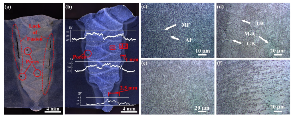
3.3. Joint Microstructure and Microhardness

According to the sidewall fusion experimental results, in laser-CMT misaligned hybrid welding, good weld formation can be obtained and lack of fusion can be prevented with suitable laser-arc configuration. Narrow gap welding was conducted using the laser-CMT misaligned hybrid welding method. A laser power of 2000 W was used for the bottom welding. Figure 8a,b show the macrographs of the narrow gap welds when X = 0 and when X = Y = 2 mm, respectively. Referring to Figure 3a, obvious lack-of-fusion regions and air pores can be seen in the weld in traditional laser-arc configuration. These defects directly affect the weld quality. In Figure 8b, lack-of-fusion defects cannot be observed, and the number of air pores decreased significantly. The maximum HAZ width was about 1 mm. The sidewall fusion quality significantly improved in laser-CMT-misaligned hybrid welding. When using arc welding alone for narrow gap welding, lack-of-fusion defects can be avoided by increasing the heat input, but a large HAZ will form [14]. When laser welding is used, a high machining accuracy of the groove is required, otherwise lack-of-fusion defects will likely occur [21]. In traditional laser–arc hybrid welding, the arc may lead to the deflection and burning of the sidewall, thereby causing defects [24]. All the above issues can be avoided in the proposed laser-CMT hybrid welding method by using a misaligned laser and arc.
The microstructure of the weld is shown in Figure 8c–f. Figure 8c shows the microstructure of the weld zone. The grain microstructure is composed of large amount of acicular ferrite (AF) and a small amount of massive ferrite (MF). During the welding process, the low heat input results in a faster cooling rate of the molten metal in the weld. Figure 8d–f provide the microstructure of the HAZ. Figure 8d shows the microstructure of the intercortical HAZ. The darker area on the left is the weld zone with a clear fusion line. In the middle of the picture, the coarse grains contain granular bainite (GB) and lath bainite (LB), and some martensite-austenite (M-A). Figure 8e is the microstructure of the fine-grained HAZ. The highest temperature in this area was 1100 °C-Ac3, and the base metal structure underwent recrystallization during thermal cycling, resulting in uniform and fine ferrite and granular bainite structures. Figure 8f shows the coarse-grained HAZ, where the brighter polygonal ferrite structure of the base metal was mixed with the fine-grained HAZ microstructure.
The white horizontal line in Figure 8b shows the location of the hardness test. The line graph shows the hardness distribution of the weld. The hardness of the base metal was approximately 250 HV. At the HAZ, the coarse grains led to an increment in hardness. The AF inside of the welding zone was produced by a rapid cooling environment, which obtained greater hardness, producing an average hardness of 326 HV. The hardness of the position between the layers in the welding seam decreased. This was due to the reheating effect that acted on the next welding seam from the previous welding seam during the multi-layer welding process, which softened the interlayer structure and reduced the hardness, respectively.

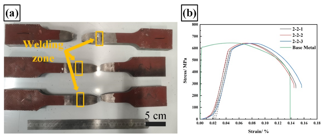
3.4. Mechanical Performance

Figure 9 shows the fracture tensile specimens and the stress-strain curves. The fracture positions of the tensile specimens were all located in the base metal and away from the welding zone (Figure 9a). The tensile strength of the weld reached 641.8 MPa, which was close to the 645 MPa of the base metal. The narrow HAZ reduced the possibility of fractures in the HAZ, increasing the strength and toughness of the joint. From the stress-strain curves, it can be seen that the elongation at break was weakened relative to the base metal. The average elongation of welds was approximately 92.2% of that of the base metal.
Figure 10 shows the fracture morphologies of a weld after the Charpy impact test. The notch of the impact specimen is located in the center of the weld. From Figure 10a, it can be seen that the structure had a ductile fracture. The impact toughness was also high, reaching an average of 172.6 J. Figure 10b presents the SEM image of the center of the fracture surface. There were several slight cracks on the surface. Figure 10c is the SEM image of one crack. It shows small-sized dimples on both sides of the crack, indicating that the material still maintains plasticity on both sides of the crack. Smaller dimples indicate higher material strength in the weld area. This is due to the weld structure being dominated by AF caused by rapid cooling, which was the result of the low heat input in the weld area. Therefore, the welding area has higher strength and lower toughness than other areas. Figure 8d is the SEM image of the impact fracture of the weld under high magnification. The size of the dimples was uniformly distributed. In addition, spherical particles can be observed in the dimples. The energy dispersive spectroscopy (EDS) analysis conducted shows that the spherical particles were composed of Fe-Mn-Si-O. This was the result of using the carbon dioxide-argon gas mixture as shielding gas during welding, which produces an oxidizing arc environment. In such an environment, Mn combines with oxygen to produce hard spherical oxides to deoxidize the weld. During deformation, plasticity was achieved through dislocation slip [25]. Stress concentration occurred between the oxide surface and the base metal of the weld, resulting in a break in microcracks, while the spherical Mn-Si-O compound remained inside the dimple. The size of the uniform dimples proved that the uniform distribution of manganese oxides in the weld was capable of producing the effect of dispersion strengthening, which improved the strength and hardness of the weld.

4. Conclusions

This study proposed a laser-CMT hybrid welding process with a misaligned laser and arc for the narrow gap welding. The sidewall of the narrow gap was melted by the laser, and its bottom was melted by the arc. The main conclusions are as follows:
(1)
The effects of different distance parameters (welding direction and perpendicular to welding direction) between the laser and the wire tip (arc) on the weld formation were compared and analyzed. A well-formed and defect-free weld can be obtained with the distance of X = 2 mm, Y = 2 mm.
(2)
When the laser was too close to the wire tip in the welding direction, the arc melted the sidewall, causing the molten metal to flow down and accumulate. The bottom of the sidewall was blocked from irradiating the laser light, resulting in a lack-of-fusion defect.
(3)
A weld with a narrow HAZ and without lack-of-fusion defects can be obtained in the narrow gap welding. The microstructure is dominated by acicular ferrite with an average hardness of 326 HV. The fracture position in the tensile test was located at the base metal, and the impact fracture mode was ductile fracture.

Author Contributions

Funding acquisition, Z.L. and D.Z.; investigation, D.Z. and X.Z.; methodology, Z.L. and B.Z.; visualization, Y.Y. and Y.B.; writing—original draft, B.Z. and Y.L.; formal analysis, B.Z. and S.A.; writing—review & editing, S.M.M. and Y.L. All authors have read and agreed to the published version of the manuscript.

Funding

This research was funded by the National Natural Science Foundation of China grant number 52075378 and 51771238 and the Natural Science Foundation of Tianjin City grant number 18JCQNJC04100.

Data Availability Statement

Data is contained within the article.

Conflicts of Interest

The authors declare no conflict of interest.

References

  1. Bagger, C.; Olsen, F.O. Review of laser hybrid welding. J. Laser Appl. 2005, 17, 2–14. [Google Scholar] [CrossRef]
  2. Shankar, S.; Mehta, K.P.; Chattopadhyaya, S.; Vilaça, P. Chapter 9—Hybrid welding technologies. In Advanced Welding and Deforming; Paulo Davim, J., Gupta, K., Gupta, K., Paulo Davim, J., Eds.; Elsevier: Amsterdam, The Netherlands, 2021. [Google Scholar] [CrossRef]
  3. Ribic, B.; A Palmer, T.; DebRoy, T. Problems and issues in laser-arc hybrid welding. Int. Mater. Rev. 2009, 54, 223–244. [Google Scholar] [CrossRef]
  4. Mehta, K. Advanced Joining and Welding Techniques: An Overview. In Advanced Manufacturing Technologies: Modern Machining, Advanced Joining, Sustainable Manufacturing; Gupta, K., Ed.; Springer International Publishing: Cham, Switzerland, 2017. [Google Scholar] [CrossRef]
  5. Mehta, K.P. Sustainability in welding and processing. In Innovations in Manufacturing for Sustainability; Springer: Berlin/Heidelberg, Germany, 2019; pp. 125–145. [Google Scholar]
  6. Serindağ, H.T.; Tardu, C.; Kirçiçek, I.; Çam, G. A study on microstructural and mechanical properties of gas tungsten arc welded thick cryogenic 9% Ni alloy steel butt joint. CIRP J. Manuf. Sci. Technol. 2022, 37, 1–10. [Google Scholar] [CrossRef]
  7. Chaturvedi, M.; Vendan, S.A. Decision Making in Welding Design. In Advanced Welding Techniques; Springer: Singapore, 2021; pp. 17–33. [Google Scholar] [CrossRef]
  8. Yu, Y.C.; Yang, S.L.; Yin, Y.; Wang, C.M.; Hu, X.Y.; Meng, X.X.; Yu, S.F. Multi-pass laser welding of thick plate with filler wire by using a narrow gap joint configuration. J. Mech. Sci. Technol. 2013, 27, 2125–2131. [Google Scholar] [CrossRef]
  9. Pandey, C.; Narang, H.K.; Saini, N.; Mahapatra, M.M.; Kumar, P. Microstructure and transverse shrinkage stress analysis in GTA welds of P91 steel pipe. Int. J. Steel Struct. 2017, 17, 763–774. [Google Scholar] [CrossRef]
  10. Standfuss, J.; Beyer, E.; Brenner, B.; Schedewy, R.; Dittrich, D.; Strohbach, R. Laser-multi-pass-welding of aluminiun and steel with sheet thickness above 50 mm. In International Congress on Applications of Lasers & Electro-Optics; Laser Institute of America: Orlando, FL, USA, 2015; Volume 2015, pp. 626–631. [Google Scholar]
  11. Ramakrishna R, V.S.M.; Amrutha, P.H.S.L.R.; Rahman Rashid, R.A.; Palanisamy, S. Narrow gap laser welding (NGLW) of structural steels—A technological review and future research recommendations. Int. J. Adv. Manuf. Technol. 2020, 111, 2277–2300. [Google Scholar] [CrossRef]
  12. Hnninen, H.; Aaltonen, P.; Brederholm, A.; Ehrnstén, U.; Virkkunen, I. Dissimilar metal weld joints and their performance in nuclear power plant and oil refinery conditions. VTT TIEDOTTEITA 2006, 2347, 208. [Google Scholar]
  13. Zhang, G.; Shi, Y.; Zhu, M.; Fan, D. Arc characteristics and metal transfer behavior in narrow gap gas metal arc welding process. J. Mater. Process. Technol. 2017, 245, 15–23. [Google Scholar] [CrossRef]
  14. Li, F.; Sun, Q.; Jin, P.; Liu, Y.; Chen, M.; Li, J.; Hou, S.; Wang, M.; Ji, Y. Wetting behavior of melt and its effect on lack of fusion in arc oscillating NG-GTAW. J. Mater. Process. Technol. 2021, 296, 117176. [Google Scholar] [CrossRef]
  15. Sokolov, M.; Salminen, A.; Kuznetsov, M.; Tsibulskiy, I. Laser welding and weld hardness analysis of thick section S355 structural steel. Mater. Des. 2011, 32, 5127–5131. [Google Scholar] [CrossRef]
  16. Zhang, X.; Mi, G.; Chen, L.; Jiang, P.; Shao, X.; Wang, C. Microstructure and performance of hybrid laser-arc welded 40 mm thick 316 L steel plates. J. Mater. Process. Technol. 2018, 259, 312–319. [Google Scholar] [CrossRef]
  17. Sharma, S.K.; Maheshwari, S. A review on welding of high strength oil and gas pipeline steels. J. Nat. Gas Sci. Eng. 2017, 38, 203–217. [Google Scholar] [CrossRef]
  18. Markushov, Y.; Evtihiev, N.; Grezev, N.; Murzakov, M. Multipass Narrow Gap of Heavy Gauge Steel with Filler Wire. Phys. Procedia 2015, 71, 267–271. [Google Scholar] [CrossRef]
  19. Zhengwu, Z.; Xiuquan, M.; Chunming, W.; Gaoyang, M. Grain refinement and orientation alternation of 10 mm 316L welds prepared by magnetic field assisted narrow gap laser-MIG hybrid welding. Mater. Charact. 2020, 164, 110311. [Google Scholar] [CrossRef]
  20. Mathieu, A.; Tkachenko, I.; Tomashchuk, I.; Cicala, E.; Bolot, R. Laser-assisted narrow gap arc welding of an 18MND5 steel thick plate. Procedia CIRP 2020, 94, 551–556. [Google Scholar] [CrossRef]
  21. Yang, T.; Liu, J.; Zhuang, Y.; Sun, K.; Chen, W. Studies on the formation mechanism of incomplete fusion defects in ultra-narrow gap laser wire filling welding. Opt. Laser Technol. 2020, 129, 106275. [Google Scholar] [CrossRef]
  22. Gao, M.; Chen, C.; Gu, Y.; Zeng, X. Microstructure and Tensile Behavior of Laser Arc Hybrid Welded Dissimilar Al and Ti Alloys. Materials 2014, 7, 1590–1602. [Google Scholar] [CrossRef]
  23. Zhang, C.; Li, G.; Gao, M.; Yan, J.; Zeng, X.Y. Microstructure and process characterization of laser-cold metal transfer hybrid welding of AA6061 aluminum alloy. Int. J. Adv. Manuf. Technol. 2013, 68, 1253–1260. [Google Scholar] [CrossRef]
  24. Wang, C.; Mi, G.; Zhang, X. Welding stability and fatigue performance of laser welded low alloy high strength steel with 20 mm thickness. Opt. Laser Technol. 2021, 139, 106941. [Google Scholar] [CrossRef]
  25. Wang, X.; Guan, R.; Misra, R.; Wang, Y.; Li, H.; Shang, Y. The mechanistic contribution of nanosized Al3Fe phase on the mechanical properties of Al-Fe alloy. Mater. Sci. Eng. A 2018, 724, 452–460. [Google Scholar] [CrossRef]
Figure 1. (a) Schematic diagram of sidewall fusion experiment; (b) schematic diagram of weld groove in the narrow gap welding.
Crystals 12 00832 g001
Figure 2. The schematic diagram of the welding process. (a) Experimental set-up. (b) The relative position of the laser and the wire (arc). (c) Side view of welding process. (d) Misaligned laser and arc in the front view of welding direction. (e) Traditional laser and arc configuration in the front view of welding direction.
Crystals 12 00832 g002
Figure 3. Size of (a) tensile test sample; (b) impact test sample.
Crystals 12 00832 g003
Figure 4. Macroscopic morphology of the weld with traditional distribution (X = 0, Y = 2 mm).
Crystals 12 00832 g004
Figure 5. Macroscopic morphology of the weld with different misaligned laser–arc distances (W = 0).
Crystals 12 00832 g005
Figure 6. Different distance parameters with (a) weld edge forming angle (b) weld bottom width.
Crystals 12 00832 g006
Figure 7. (ac) images of welding process; (dh) schematic diagram of the lack of fusion defects formed at the weld root.
Crystals 12 00832 g007
Figure 8. Joint macro/microstructure and microhardness: (a) joint with tradition distribution; (b) joint with misaligned distribution and microhardness; (cf) microstructure of the joint.
Crystals 12 00832 g008
Figure 9. (a) Tensile specimen after fracture; (b) Stress-strain curves.
Crystals 12 00832 g009
Figure 10. Charpy impact fracture of weld: (a) macrostructure; (bd) SEM.
Crystals 12 00832 g010
Table 1. The chemical composition of X80 steel and ER80-S welding wire (wt.%).
Materials (wt.%)CSiMnPSCrMoNiVTiCuAlFe
X800.090.191.770.0100.0010.30.20.130.0010.010.10.03Bal.
ER80-S0.080.71.310.0140.0141.220.510.02--0.12-Bal.
Publisher’s Note: MDPI stays neutral with regard to jurisdictional claims in published maps and institutional affiliations.

