1. Introduction
Ni-based single crystal superalloys have been designed to maximise the combination of significantly high mechanical strength and surface stability at high operating temperatures, allowing severe mechanical stressing to nearly 80% of the melting point, and are thus ideal for turbine blade applications [
1,
2,
3,
4]. The superior properties of the superalloy are mainly due to two hardening mechanisms: one is solid-solution hardening by the addition of different soluble elements, such as cobalt, chromium, molybdenum, tungsten and rhenium, and the other is precipitation hardening by the relatively uniform precipitation of high volume fractions of the ordered γ′ phase (Ni
3(Al, Ta, Ti)) in the face-centred cubic structure matrix (γ phase) [
1,
3,
4,
5,
6,
7,
8,
9]. To maximise design flexibility and minimise manufacturing cost, current Ni-based superalloy turbine blades are produced by investment casting, which can produce hollow aerofoils with complex internal cooling passages, and for the highest performance, eliminate grain boundaries [
4]. The casting process forms dendrites, containing the primary phase of γ and fine γ′ precipitates, with a specific direction of {001}, followed by eutectic γ and γ′ in the interdendritic region. This mixed microstructure is undesirable in the highest performing turbine components, due to an inhomogeneous chemical distribution, which consequently requires homogenisation during the subsequent heat treatment [
10]. Therefore, a number of studies have investigated the interdendritic γ and γ′, and the casting microsegregation, in order to tune the homogenisation cycle to remove them [
11,
12].
EPMA (electron probe micro-analysis) using X-ray wavelength dispersive spectroscopy (WDS) has been widely used to analyse the chemical composition of the interdendritic γ and γ′ due to the size of the dendritic microstructure in an as-cast turbine blade. For accurate analysis, multiple WDX points scans were performed, and the compositions of γ and γ′ in dendrite core and interdendritic regions, and the partitioning behaviour of alloying elements, were then averaged [
11,
12]. During EPMA analysis, a focused electron beam (typical energy = 5–30 keV) bombards a micro-volume of a targeted sample, and X-ray photons emitted near the surface are then collected and identified by WDS spectra [
13]. Generally, the spot size of the electron beam is 10 μm at an accelerating voltage of 20 kV and a beam current of 100 nA [
11] or, in an extreme analysis case, the beam diameter is approximately 1 to 2 μm [
14]. In addition, when the electron beam bombards the target, there is an interaction volume of beam/sample with a depth range of a few micrometres depending on the acceleration voltage of the electron beam and the atomic number of the targeted sample [
15,
16]. However, in nickel-based single crystal superalloy turbine blades, the size of the γ phase, formed as γ channels, is just a few hundreds of nanometres, which means that the spot size of the electron beam and the interaction volume of beam/sample are much larger than that of the γ phase. As a result, even though the electron beam is targeted to bombard just the thin γ phase, it is inevitable that the analysis includes a number of X-ray photons emitted from the surrounding bulky γ′ in the chemical composition analysis using EPMA.
Another analysis technique for the compositions of γ and γ′ is the use of TEM due to their fine sizes. As it is hard to access the correct location, i.e., the dendrite core or the interdendritic region, with conventional TEM sample preparation techniques, a focused ion beam (FIB) lift-out technique has been widely used to fabricate TEM samples [
17,
18,
19,
20,
21,
22]. Even though a lamella can be fabricated precisely from the core or the interdendritic region, its size is usually just about 10 μm, which means that one lamella cannot completely contain the two regions. Therefore, two different lamellae need to be fabricated—one from the core, the other from the interdendritic region—in order to investigate the microstructure and the compositions of γ and γ′ in the core and the interdendritic region. However, there is the possibility of the contamination of the first lamella during the fabrication of the second sample, even though this contamination may be minor, which may affect the compositional analysis. In addition, it is hard to make two lamellae with almost the same thickness. Importantly, during TEM observation, it is almost impossible to observe two lamellae under the same observation and analysis conditions. Therefore, in this study, a modified TEM sampling method using a FIB lift-out technique was used to make two lamellae on one TEM grid, and the microstructure and the compositions of γ and γ′ in the core and the interdendritic region were investigated by electron microscopy.
2. Experiment
Nickel-based single crystal turbine blades were commercially manufactured in an aerospace production manufacturing facility at Rolls-Royce plc. In this study, a third-generation superalloy (CMSX-10N, Cannon Muskegon Corp., Muskegon, MI, USA) was used and the composition is summarised in
Table 1. The detailed casting condition and procedure have been described elsewhere in detail [
1,
11,
12].
For investigation of the as-cast microstructures of the blades, the components were removed from the gating system prior to heat treatment and cut out by wire-guided electro-discharge machining (EDM). Then, they were mounted, mirror-polished, etched, and ultrasonically cleaned in ethanol for 5 min for microstructural investigation.
Firstly, the as-cast tip of a blade was observed without any polishing or etching process, and the etched samples were then observed using a high-resolution scanning electron microscope (field emission (FE)-SEM, FEI Quanta 3D dual beam FIB-SEM, ThermoFisher Scientific, Hillsboro, OR, USA) equipped with an energy dispersive X-ray spectroscopy (EDX) system and a focused ion beam (FIB) facility. After SEM observation, TEM samples were fabricated in the same chamber by an in situ FIB lift-out technique [
23,
24]. As the superalloy has more than 10 alloying elements and some have close proximity characteristic X-rays (M
α, keV), such as Hf (1.644), Ta (1.709), W (1.774), and Re (1.842) [
6,
25], a high-resolution transmission electron microscope (FE-TEM, FEI Tecnai F20, ThermoFisher Scientific, Hillsboro, OR, USA) equipped with a scanning mode (STEM) and an EDX system was used at an operational voltage of 200 kV. Chemical compositions of the regions of interest were acquired by silicon drift detectors installed into the STEM with a nominal probe size of about 2 nm from more than 10 analysis areas to provide sufficient statistical confidence. These data were quantified using the analysis software (Oxford AZtecTEM, Oxford Instruments, High Wycombe, UK) installed on the equipment, which can perform a standardless analysis [
26] and resolve differences of more than 0.03 keV by the deconvolution of overlapping elements and background removal [
19,
27]. To avoid or minimize microstructural changes in the irradiated area, TEM samples were cooled with liquid nitrogen during observation [
24].
3. Results and Discussion
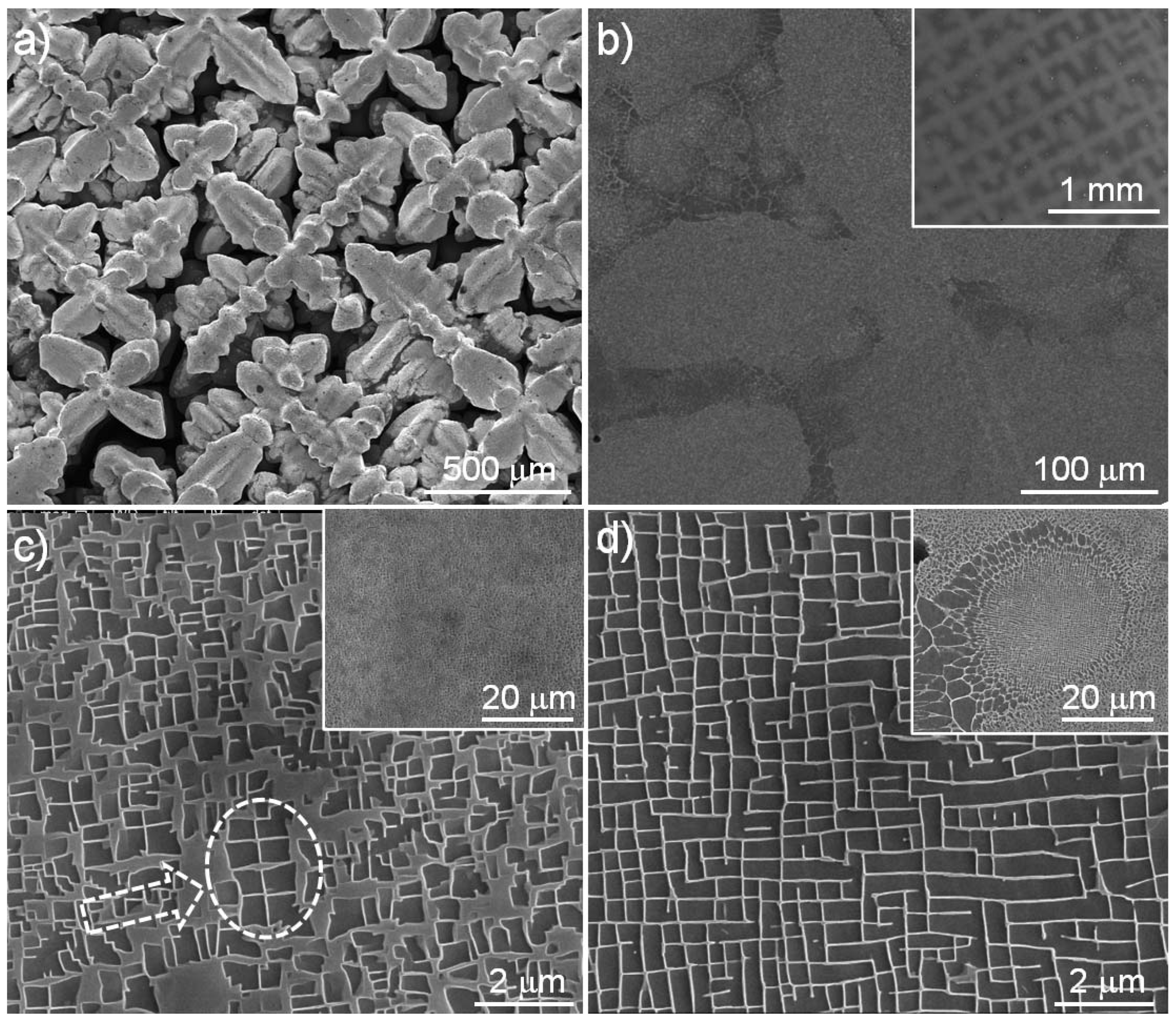
Figure 1 shows a typical microstructure of an as-cast nickel-based single crystal turbine blade. Through the whole turbine blade, dendrites were well developed along the specific {001} direction during casting and they were clearly visible at the tip of a blade, as shown in
Figure 1a. The figure also shows a typical microstructure with mainly one dendrite after epoxy resin mounting, polishing, and etching. The dendrite with bright contrast and the interdendritic region with relatively dark contrast were clearly distinguishable at this magnification. The general dendritic microstructure and its formation mechanism are well understood and have been described elsewhere [
1,
3,
4,
12,
28].
Figure 1c,d clearly show the microstructures at the dendrite core and in the interdendritic region. It should be emphasised that the micrographs were acquired exactly at the same magnification. The dendrite core shows almost uniform bright contrast at a low magnification of 5000× (the insert in
Figure 1c). However, an image acquired at a higher magnification of 25,000× reveals a number of particles (γ′ phase) of dark contrast and this γ′ phase was not uniformly precipitated in the core because the turbine blade was only cast without further processes such as solution and aging heat treatments, which form the more familiar microstructure composed of uniformly precipitated γ’ and thin γ channels. It should be noted that similar micrographs were acquired through the whole core region, which means that the γ′ phase in the core was not well developed during casting. Compared with the core, the interdendritic region showed a quite different microstructure even at a low magnification of 5000× (the insert in
Figure 1d); there are a number of coarse or elongated γ′ particles (see also
Figure 2). The main image in
Figure 1d, which was acquired at the same magnification as
Figure 1c, shows a clearly different morphology of bright γ channels and dark γ′ particles. These observation results suggest that the morphology of the core and the interdendritic regions is quite different and, consequently, the formation mechanism of the core and the interdendritic region is also probably different.
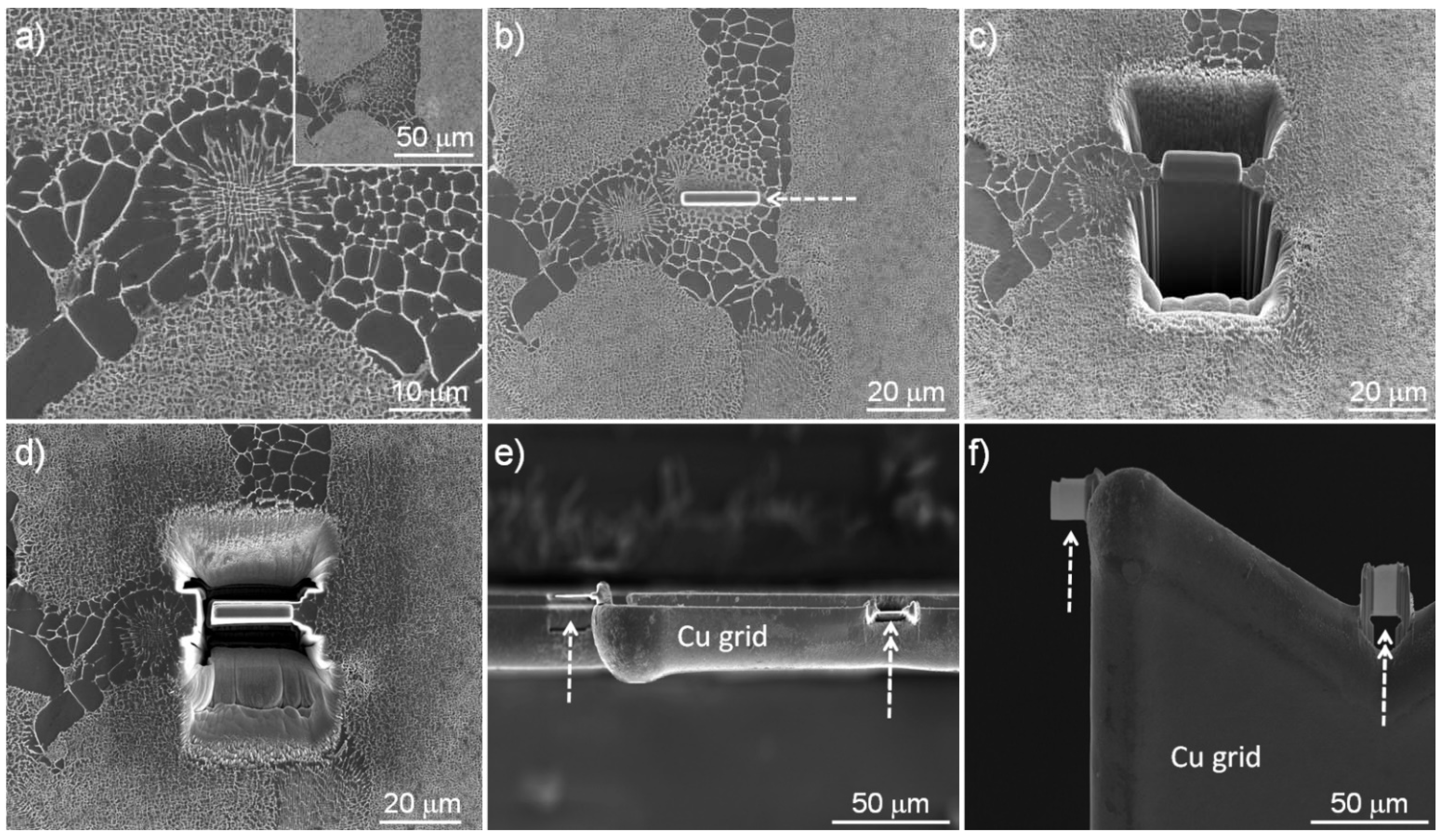
It should be noted that the core region showed a relatively consistent microstructure through the whole turbine blade, while the interdendritic region showed different microstructure depending on the observation region; thus, another representative region was selected and observed, as shown in
Figure 2. In this figure, the central region was the interdendritic region surrounded by three dendrites. Due to the different contrast, the interdendritic region is easily recognised. Compared to the core, there are a smaller number of relatively dark contrast particles. It should be emphasised that the size of these dark contrast particles near the interface of core/interdendritic region is larger than those in the centre of the interdendritic region. In addition, the centre of the interdendritic region shows a similar morphology of γ and γ’ to the core in
Figure 1d.
This formation of the large particles and regular morphology of γ and γ’ has been considered to be probably due to either eutectic or peritectic reaction [
10]. It was necessary to investigate the composition of γ and γ’ in the interdendritic region to confirm the reaction. As previously stated, the inherit interaction volume (a few micrometres) during SEM-EDX analysis makes the measurement of the composition of γ and γ’ difficult. Therefore, a specific TEM sampling method using a focused ion beam (FIB) lift-out technique was used. First of all, a region was selected (
Figure 2a) and a platinum layer, which is marked with an arrow in
Figure 2b, was deposited on the surface to protect the sample from ion beams during FIB milling and thinning. Then, a typical FIB lift-out technique was carried out (
Figure 2c,d), and, finally, the thin lamella was lifted out by a manipulator and placed on the left part of a copper grid (
Figure 2e). Then, unlike the typical TEM preparation process, the lamella on the grid was not thinned further. Instead, in this study, another lamella was fabricated and placed on the same grid in the same chamber without removing the grid. This avoided any contamination of the first lamella during the second sample fabrication, made lamellae with almost the same thickness, and crucially allowed observation of the lamellae under the same observation and analysis conditions. To allow comparison of the compositions of the γ and γ’ phases at the core and the interdendritic region, the second lamella was fabricated from the core and placed on the central part of the grid, which is marked with a double arrow in
Figure 2e. Following this, the lamellae were thinned to almost the same thickness.
Figure 2f shows two lamellae on a copper grid. The bright region in each lamella is electron-transparent during TEM observation. After additional milling and cleaning, the TEM sample preparation was completed and, finally, plain view SEM images from the lamellae were acquired to measure the thickness of two lamellae. Then, the sample was immediately observed by TEM to avoid any air contamination.
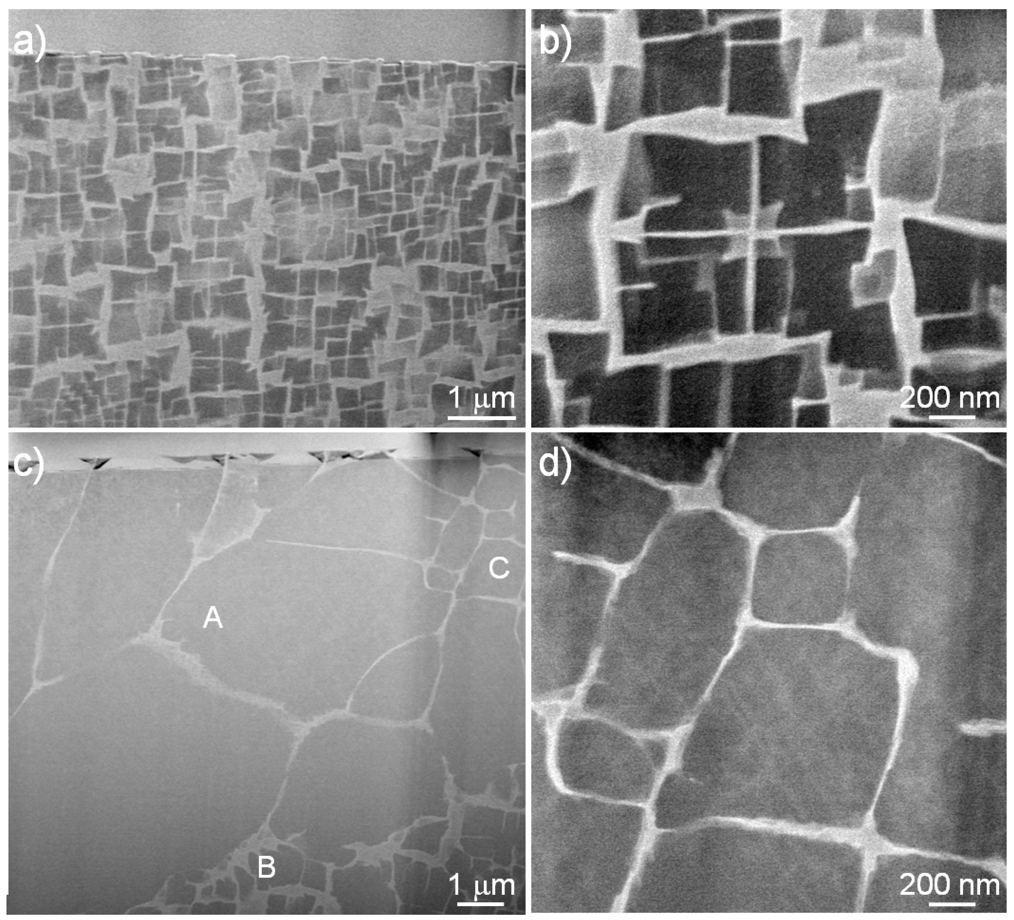
Figure 3 shows STEM-HAADF images acquired from two different regions of the core and the interdendritic region. The top bright layer in
Figure 3a,c, indicates the protective platinum layer, which means that the region was preserved without any critical damage during FIB sampling. It should be noted that compared to a normal TEM sample, the lamellae were thinned less in order to preserve the whole cross section of the region of interest, even though this affected the image quality at high magnification. Nonetheless, it is clear that two different morphologies at the core (
Figure 3a,b) and the interdendritic region (
Figure 3c,d) are visible and distinguishable.
The core region shows an irregular morphology of the γ’ phase in γ. The precipitation of γ’ is affected by the elastic modulus anisotropy in the turbine blade and usually forms a cuboidal morphology [
29]. However, in this study, the turbine blade was not fully heat-treated but as-cast. Therefore, there was not sufficient time to form the complete morphology composed of cuboidal γ’ precipitation in the γ matrix due to the relatively short casting time compared to the aging heat treatment used for this alloy. By comparison, the interdendritic region showed a completely different microstructure. There are primarily three different regions, which were marked as ‘A’, ‘B’, and ‘C’: the first (A) was composed of several elongated γ’ particles shown in the top and middle of
Figure 3c, the second (B) was composed of relatively tiny and irregular γ’ in the bottom of
Figure 3c, and the third (C) contained γ’ with relatively regular morphology on the right of
Figure 3c,d. This observation was in good agreement with other SEM observation results of the interdendritic region, and the previous images in
Figure 1 and
Figure 2.
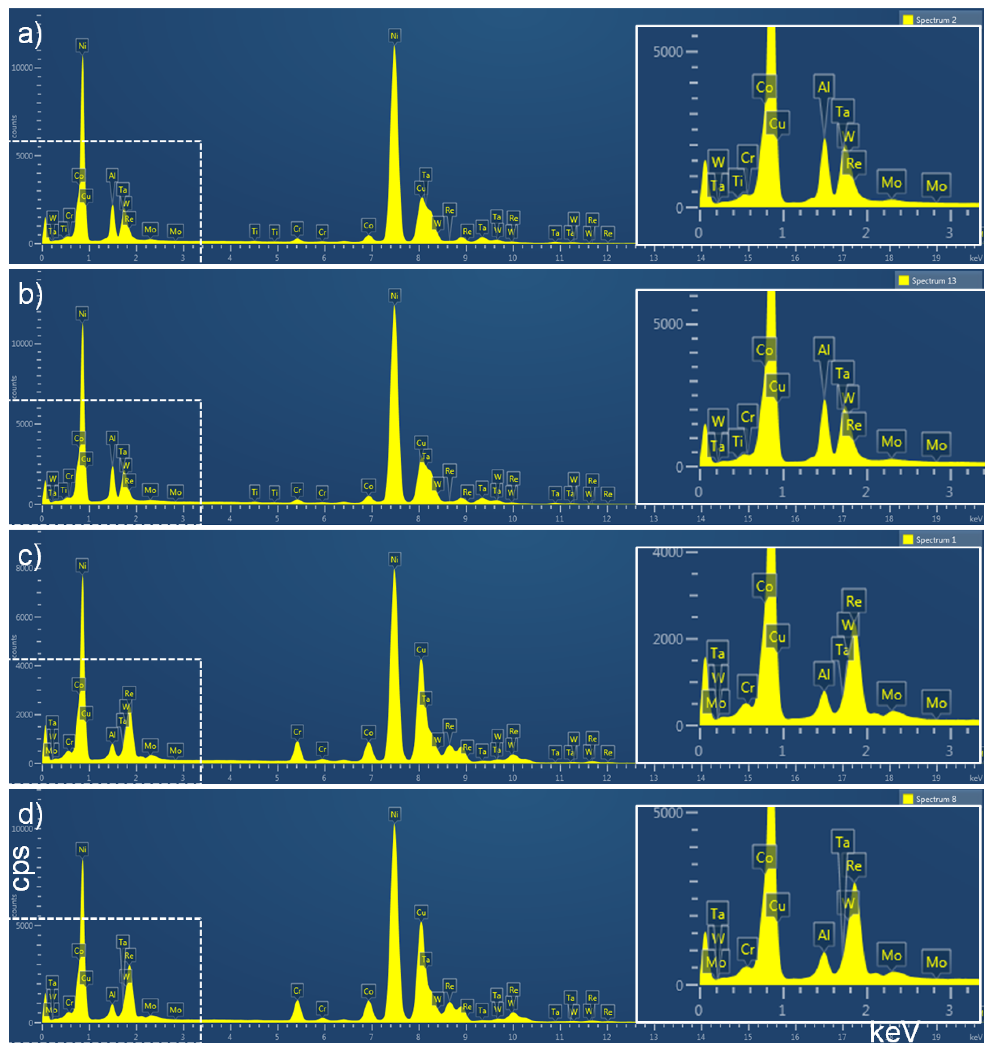
Figure 4 shows several STEM-EDX spectra acquired from the TEM samples in
Figure 3. As a comparison, the core region was also analysed.
Figure 4a,b are spectra of γ’ acquired from the core (
Figure 4a) and the interdendritic region (
Figure 4b), respectively. As expected, strong peaks of nickel, aluminium, and tantalum were detected.
However, it is hard to distinguish the spectrum of the core γ’ from that of the interdendritic γ’ region despite repeating the STEM-EDX analysis in over ten areas. Thus, STEM-EDX point analysis was performed on the γ in the core (
Figure 4c) and in the interdendritic region (
Figure 4d), respectively. Compared to the compositional results of γ’, stronger peaks of chromium, cobalt, and rhenium were acquired.
However, the spectra acquired from the γ also show a similar trend to that of the γ’; specifically, it is hard to distinguish the spectrum acquired from the γ in the core with that from the γ in the interdendritic region. Based on the spectra, the chemical compositions of γ and γ’ in the core and in the interdendritic region were acquired and are summarised in
Table 1. As shown in the spectra, the composition of γ’ in the core is almost the same as that of γ’ in the interdendritic region. In addition, the composition of γ in the core is also the same as that of γ in the interdendritic region. This result shows that when the γ’ forms in the γ matrix, the composition of γ’ is almost uniform regardless of the casting area, despite the bulk composition in these two regions being different due to the segregation during casting. It should be noted that even in the interdendritic region, some heavy alloying elements, such as rhenium and tungsten, were clearly detected, and they are also present in the γ’ particles. For a comparison, the compositions acquired from fully heat-treated turbine blades are also included in
Table 1.
During STEM-EDX analysis, it should be noted that the spectrum and composition of γ’ in the interdendritic region was acquired from the γ’ on the right and the bottom regular type region in
Figure 3c or in
Figure 3d. STEM-EDX point analysis was also carried out on the elongated γ’ in
Figure 3c. The spectrum showed slightly high peaks of aluminium and titanium, but which are similar to the peaks in
Figure 4. The composition acquired from the elongated γ’ is also summarised in
Table 1. It is clear that the amounts of aluminium and tantalum in the elongated γ’ are slightly higher than those in the rest of the interdendritic region or in the core. It should be noted that the compositions of γ and γ’ in the core and the interdendritic region, where there is a mix of γ and γ’, remain the same with the general compositional differences being accommodated through the varying of the proportions of γ and γ’. However, the composition of the elongated γ’ in the interdendritic region was slightly different, with higher aluminium than the other γ’ areas. The general composition in these areas does not sit between the γ and γ’ compositions seen elsewhere, so the microstructure becomes made up of large areas of γ’ in an attempt to reach the preferred composition. The compositions of aluminium and tantalum were shown to be the most variable. These results demonstrate that the last portion to solidify in the casting has to accommodate all the γ’ forming elements at the expense of forming no further γ; hence, the size of the γ’ particles.
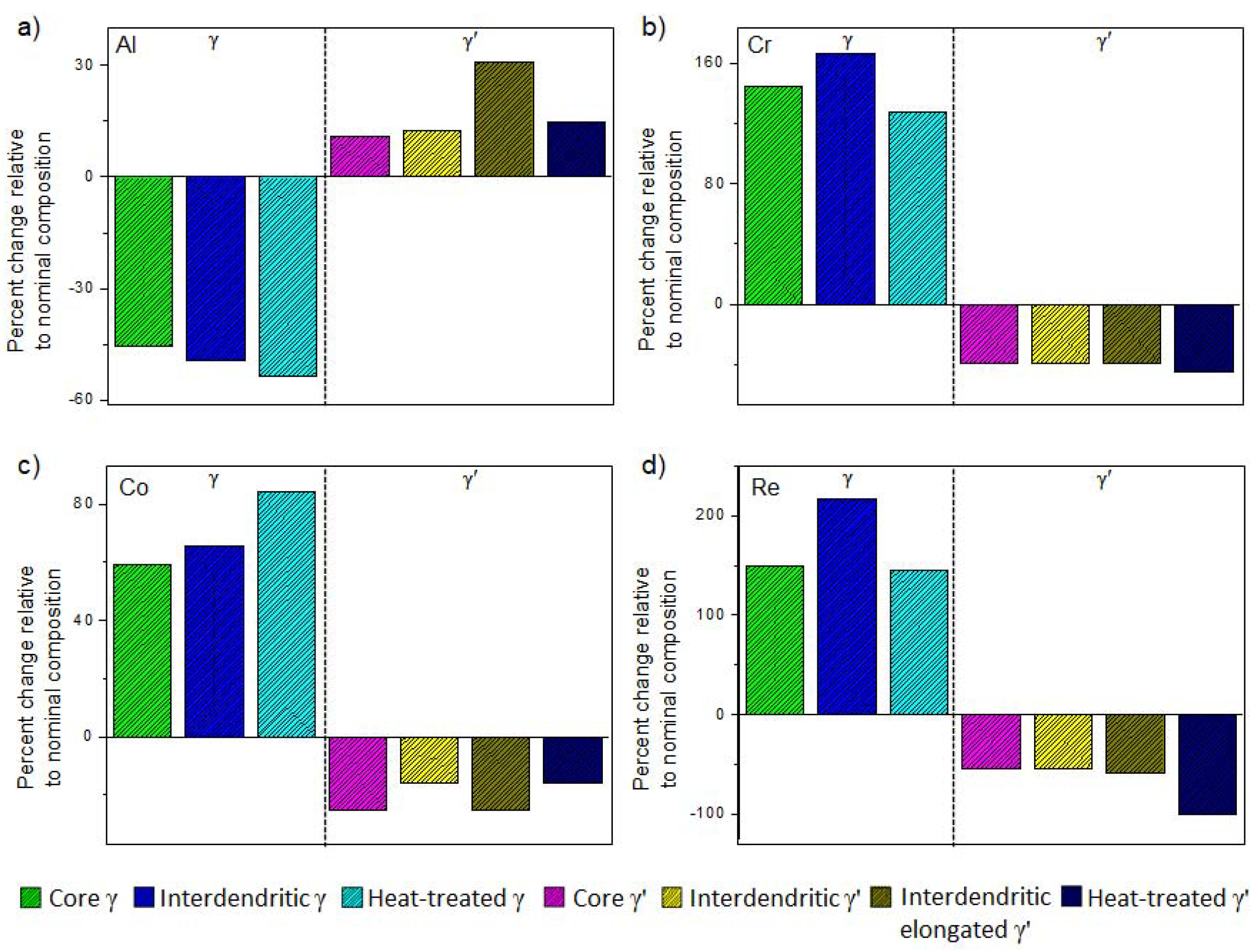
Based on the chemical compositions in
Table 1, the partitioning behaviour of main alloying elements is summarised in
Figure 5. As is well known, aluminium is strongly partitioned to the γ’,
Figure 5a, but is of consistent composition, except for the interdendritic elongated γ’ where there is a higher concentration. Chromium (
Figure 5b) and cobalt (
Figure 5c) show different behaviour to aluminium and it is difficult to identify a trend between the dendrites, the interdendritic regions, and the fully heat-treated material. Rhenium (
Figure 5d) shows relatively high concentrations in the interdendritic γ when compared to γ in other locations and the heat-treated state, but as there is relatively little γ to accommodate the rhenium present, the composition here is increased. The presence of excess rhenium here means that it is not necessary for rhenium, which has the slowest diffusion rate of the alloying elements in the base material [
30,
31,
32], to diffuse long distances from the core to the interdendritic region to enable a uniform microstructure composed of thin γ channels and a fine precipitate of γ’ during subsequent heat treatment.
It is well documented that during solidification through dendritic growth, the higher melting point elements preferentially solidify in the dendrites, whereas the lower melting point elements are preferentially pushed into the interdendritic areas. This is true in nickel-based superalloys but this does not lead to total partitioning, only changes in local composition in line with these drivers [
4]. The alloy can be seen to behave as a pseudo-binary with two preferred compositions; the local composition only changes the proportions of γ and γ’ seen locally rather than changing the compositions of the γ and γ’ to accommodate the local composition. This description explains the formation of the observed microstructures in both the core and interdendritic areas. It also explains the large areas of γ’ that form adjacent to the dendrites, because this is the area of the casting that is richest in aluminium as it is ejected from the solidifying dendrite cores; the amount of aluminium present is higher than the preferred amount of aluminium in equilibrium γ’ and hence γ’ is formed. The rhenium in the interdendritic regions is ejected into the small amount of γ available, hence increasing the rhenium content in the γ in these regions.


