Article

Microstructure and Mechanical Property of a Multi-Scale Carbide Reinforced Co–Cr–W Matrix Composites

1
Institute of Metal Research, Chinese Academy of Sciences, 72 Wenhua Road, Shenyang 110016, China
2
School of Materials Science and Engineering, Harbin Institute of Technology, 92 West Da-Zhi Street, Harbin 150001, China
*
Authors to whom correspondence should be addressed.
Crystals 2022, 12(2), 198; https://doi.org/10.3390/cryst12020198
Submission received: 24 November 2021 / Revised: 7 December 2021 / Accepted: 9 December 2021 / Published: 28 January 2022

Abstract

:
In order to meet the demand for high wear-resistant Co-based material used in fields such as aerospace, energy, medical, etc., this study attempts to improve the comprehensive performance of this material by adding some reinforced phases and adjusting the sintering temperature. Results indicate the pure Co–Cr–W alloy is composed of γ-Co, M29C, and M6C (Ni3W3C), and the Co–Cr–W matrix composites are composed of γ-Co, M29C, M6C (Co2W4C), M23C6, and WC. With increasing the hot-pressing sintering temperature, the element diffusion in the material becomes sufficient, and the microstructure of Co–Cr–W alloy and composites materials becomes denser. When the sintering temperature is over 1150 °C, the bending strength and the toughness of the Co–Cr–W matrix composites are higher than that of the pure Co–Cr–W alloys. The added reinforced phases help the composites to gain a multi-scale strengthening effect, which makes the composites have a more comprehensive performance. Our results emphasize the importance of added reinforced phases and help to optimize the preparing process in preparing the Co–Cr–W alloys.

1. Introduction

In the late 1920s, the United States Stellite company developed a Co-based wear-resistant alloy for the aero-engine exhaust valve. Since the application, many researchers have paid attention to the alloy, and Stellite has gradually developed a series of Co–Cr–W alloys. Co–Cr–W alloy has excellent wear resistance, corrosion resistance, and heat strength and is widely used in aerospace, ships, oil and gas, nuclear industry, and other wear-resistant environments, and it also has broad application prospects in medical treatment, system manufacturing, and many other fields [1,2,3,4,5,6].
Co–Cr–W alloy is a Co-based alloy, and Cr, W, and other elements are added as the reinforcing elements. Its preparation method mainly includes coating, surfacing, casting, and powder metallurgy [7,8,9]. Coating and surfacing Co–Cr–W alloys are only suitable for increasing the surface wear resistance of some parts while casting and powder metallurgy techniques are suitable for the manufacture of integral wear-resistant materials, which has a broader range of applications [10,11,12,13]. Although the casting process is simple, the carbide eutectic structures are easy to form, and the carbides formed grow up rapidly in the smelting process and are concentrated and continuously distributed in the matrix. Therefore, the contribution of the carbides to the wear resistance of the cast alloy is limited. In contrast, the Co–Cr–W alloy prepared by powder metallurgy method is composed of a Co-based solid solution and fine carbides (MC, M23C6, and M6C) [14,15]. The carbides are fine and diffusely distributed in the matrix, making the alloy have good wear resistance and strong toughness [15].
In recent years, the rapid development of aviation, aerospace, energy, medical, and other fields put forward higher requirements for the alloy with better toughness, wear resistance, high-temperature resistance, and corrosion resistance. However, the traditional powder metallurgy prepared Co–Cr–W alloy has been unable to meet the application requirements, and there is an urgent need to develop a Co–Cr–W alloy with better comprehensive performance. The effects of W, Fe, C, and other elements in the Co–Cr–W alloy have been deeply analyzed [16], and it has been found that the microstructure of the Co–Cr–W alloy changes from γ-Co+M7C3 hypoeutectic to primary carbide M7C3+M7C3 hypereutectic when the content of C in the alloy is increased; it is beneficial to increase the volume fraction of the strengthening phase, and increase the macro-hardness and improve the wear resistance. However, with the increase of C content, the primary M7C3 aggregates and grows up, and the impact resistance, weldability, and machinability of the alloy decreases [10,11,12]. Similarly, increasing the content of W in the alloy can also promote the formation of carbide phases and improve the strengthening effect and the wear resistance of the alloy. At the same time, it also increases the content of W in the γ-Co solid solution. This increases the brittleness and decreases the strength and toughness of the matrix, and the cracks and other defects are easily formed in the preparation process [17,18]. Therefore, the collaborative improvement of wear resistance, strength, and toughness just by composition optimization of the Co–Cr–W alloy has encountered a bottleneck. New methods are needed to break the bottleneck in improving the comprehensive performance of the Co–Cr–W alloys.
Considering that the strengthening mechanism of Co–Cr–W alloy is similar to that of metal matrix composites, some researchers tried to introduce the strengthening phases into the Co–Cr–W alloy. Abbas et al. [19] added SiC to the Stellite alloy, and they used the laser-cladding method to make the Stellite6+SiC coating on the En3b steel surface. By comparison, they found the Stellite6+SiC coated material increased the wear resistance three-fold, at the same time, the SiC particles decomposed, increasing the content of carbon and silicon in the cladding layer. Zhong et al. [20] carried out the relevant research on the WC/Stellite laser coated materials and found the solidification of Stellite6+WC has two ways: one is the precipitation of proeutectic, followed by eutectic, and the final structure contains dendritic proeutectic and interdendritic eutectic; the other is the formation of blocky precipitates and matrix directly. Both ways are beneficial to the wear resistance of the alloy. Xiong et al. [21] also studied the microstructure and mechanical properties of the laser-cladding WC/Stellite6 composites. They found the alloy had fine microstructure, and hardness of the cladding layer was up to 57 HRC, which is twice as hard as the matrix.
It can be seen from the previous studies a focus on the Co–Cr–W composites prepared by laser cladding. However, there are several shortcomings of this process, such as high porosity and thermal residual stress, non-uniform microstructure, etc., which make the application of this process confined to the small surface area. By contrast, the vacuum hot-pressing sintering method can conquer those problems and can reduce the sintering temperature, shorten the sintering time, and obtain fine-grain and highly compact materials [8]. An et al. [22] prepared TiBw/Ti6Al4V composites by this method and found the reinforced phases can distribute at the grain boundary, which can improve the hardness, strength, and toughness of the materials at the same time. Based on the above ideas, we propose a microstructural design idea of multi-scale carbide reinforced composites, that is, grain boundary strengthening is realized by adding some large-scale carbides under the condition of high-temperature hot-pressing and sintering, and grain strengthening of the matrix is realized by endogenous fine and uniform granular carbides. The schematic diagram [14] of the structural design is illustrated in Figure 1. The objective of this research is to determine the mechanism of action of the introduced carbides and reveal the formation mechanism of the multi-scale carbides in the Co–Cr–W matrix composites. The completion of this research can provide a theoretical basis and application guidance for structure design of high wear-resistant Co–Cr–W material.

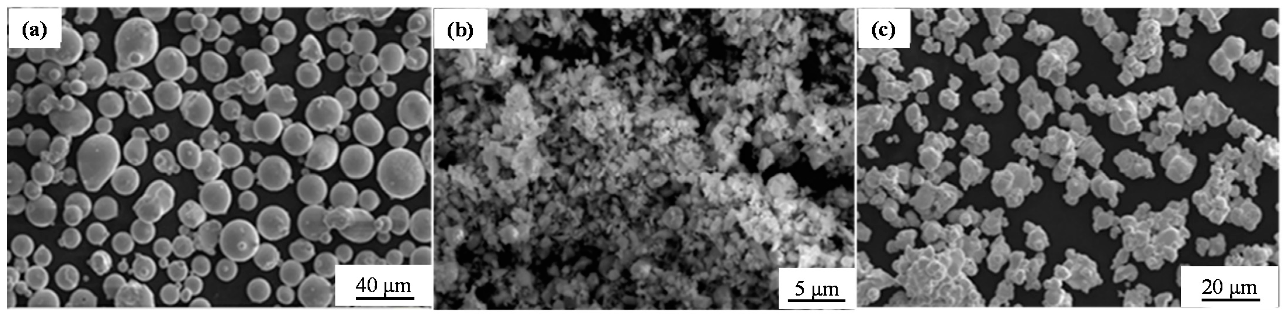
2. Experimental Methods

The Co–Cr–W alloy powder used in this research is prepared by gas atomization method, and the preparation process is as follows: first, we prepared the ingredient (solid pure Co, Cr, W, etc.) according to Table 1 and used vacuum induction melting equipment to prepare the Co–Cr–W alloy ingot with uniform composition; secondly, the alloy ingots were prepared into the spherical alloy powder by vacuum gas atomization method, and the chemical compositions are shown in Table 1; finally, the alloy powder with particle size less than 200 mesh was screened. The alloy powder is spherical and uniform, as shown in Figure 2a. The introduced strengthening phases were the Cr3C2 and WC carbide particles, which are both commercial products. The particle size of WC is less than 10 μm, and that of Cr3C2 is 200~300 nm, as shown in Figure 2b,c.
The Co-Cr-W alloy powder was mixed with 3 wt.% WC and 2 wt.% Cr3C2, and the instrument used for mixing powder was the planetary ball mill. The ball-milling speed was 140 r/min, and the ball-milling time was 3 h. After the powder mixing process, the mixed powder and the pure Co–Cr–W alloy powder were sintered by a vacuum hot-pressing and sintering furnace to make the diffusion more extensive. In this method, the dry mixed powders were filled into a model (Φ60 × 10 mm), and then the powder was pressurized in a uniaxial direction and heated at the same time, so that the molding and sintering were completed at the same time. Different sintering temperatures were set based on the phase transition temperature of the mixed powder, and the sintering temperatures were set as 1000 °C, 1100 °C, 1150 °C, and 1200 °C, respectively. After the sintering temperature was determined, hot-pressing sintering was carried out under the conditions of sintering pressure of 25 MPa and holding time of 1 h. The optimum sintering temperature was determined by analyzing the microstructure and mechanical properties of the sintered materials.
The microstructures of the prepared materials were obtained by an S-3400 scanning electron microscope (SEM). The elements distribution was analyzed by a SHIMADZU-1610 Electron Probing Microanalysis (EPMA). The phases in the prepared materials were analyzed by Tecnai-T20 transmission electron microscopy (TEM) and X-ray diffraction (XRD). The SEM and EPMA samples were cut by wire cutting equipment first, then using 120#, 320#, 600#, 1000#, 1500#, and 2000# abrasive paper to polish the samples manually in turn. Then, the polished samples were mechanically polished with Cr2O3 aqueous solution. TEM samples were prepared by double spray electrolysis. The electrolyte composition was 7% HClO4 + 93% C2H5OH (volume fraction), the coolant was dry ice, the voltage was 50 V, the current was 30 mA, and the temperature was below −20 °C.
The three-point bending experiment was carried out to test the bending strength and the toughness of the materials. The toughness of the material is characterized as follows: the energy absorbed by the material (the toughness) in the bending process was expressed by calculating the area enclosed by the stress–strain curve and the horizontal coordinates, and the unit is energy density (kJ/m3) after conversion. The instrument used for the room temperature three-point bending test was an Instron-5569 universal testing machine, and the test rate was 0.5 mm/min. The specification of the samples for the three-point bending test was 3 × 4 × 35 (mm) and Φ6 × 9 (mm), respectively. At least three samples were measured for each parameter to reduce the error.

3. Results and Discussion

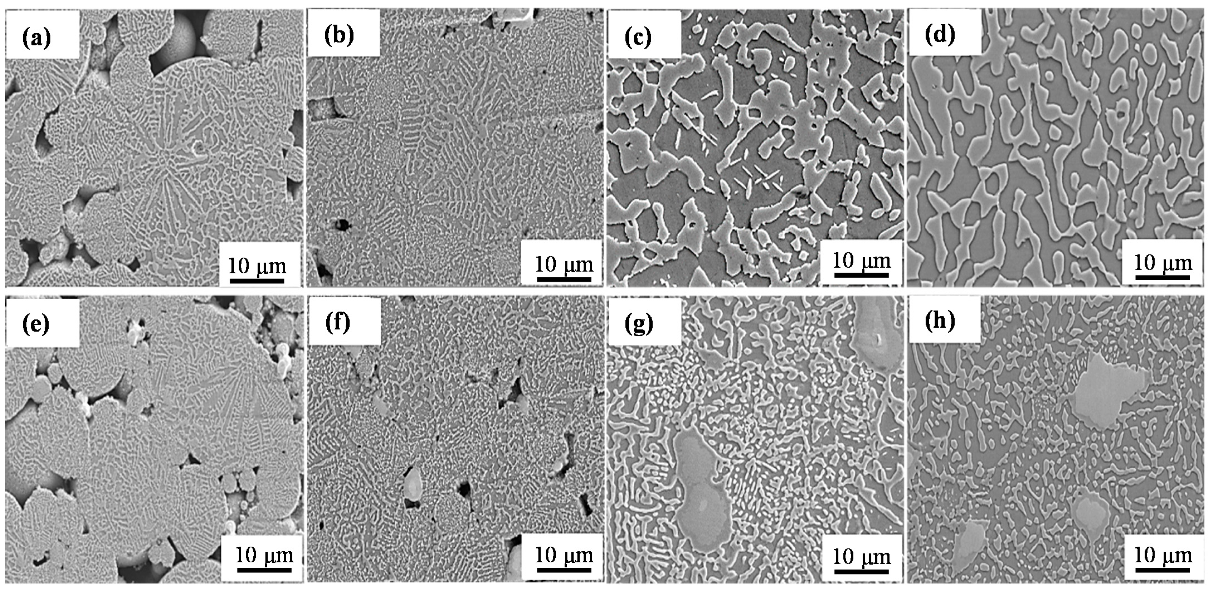
3.1. The Effect of Sintering Temperature on the Microstructures

Figure 3 shows the microstructure of the Co–Cr–W alloy and Co–Cr–W matrix composites prepared at different sintering temperatures. At the sintering temperature of 1000 °C and 1100 °C, there are many hole defects in the Co–Cr–W alloy and the Co–Cr–W matrix composites (Figure 3a,b,e,f), and the added carbides in the composites do not fully bond to the matrix. In addition, the microstructure of the Co–Cr–W alloy is consistent with that of the composites. At the sintering temperature of 1150 °C and 1200 °C, the sintered materials are compact and do not have any holes. The reinforced phases are closely combined with the matrix. Based on the results, it can be determined that the diffusion between the powders increases with the increase of sintering temperature, which increases the compactness of the materials. However, we found the materials were bonded to the mold at 1200 °C, so we inferred the materials could react with the mold at this temperature. Therefore, 1150 °C is the proper sintering temperature. In addition, increasing the sintering temperature could not change the phase constitution of the two materials based on the SEM images (Figure 3). This can also be confirmed by the following the XRD results (see Section 3.2).

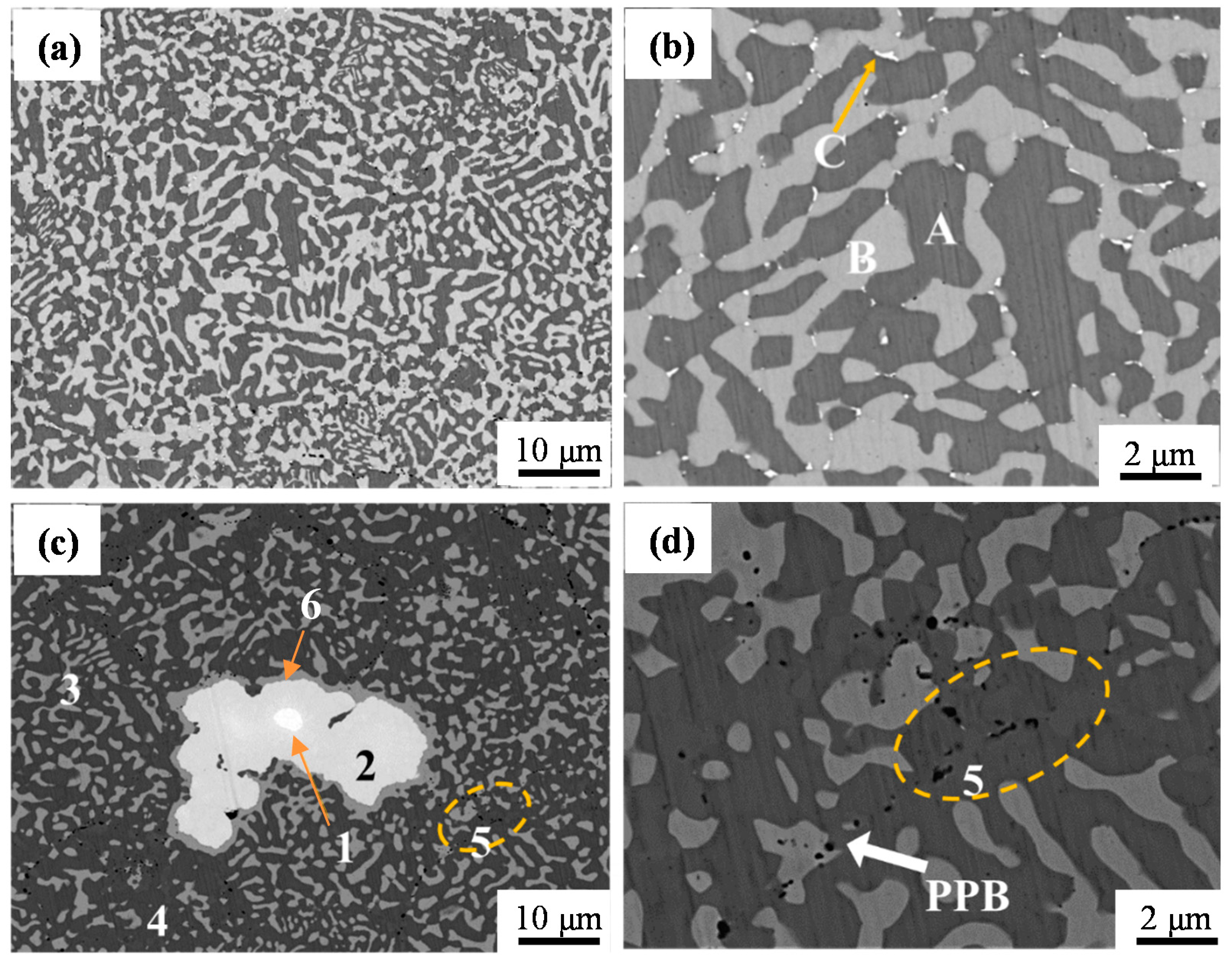
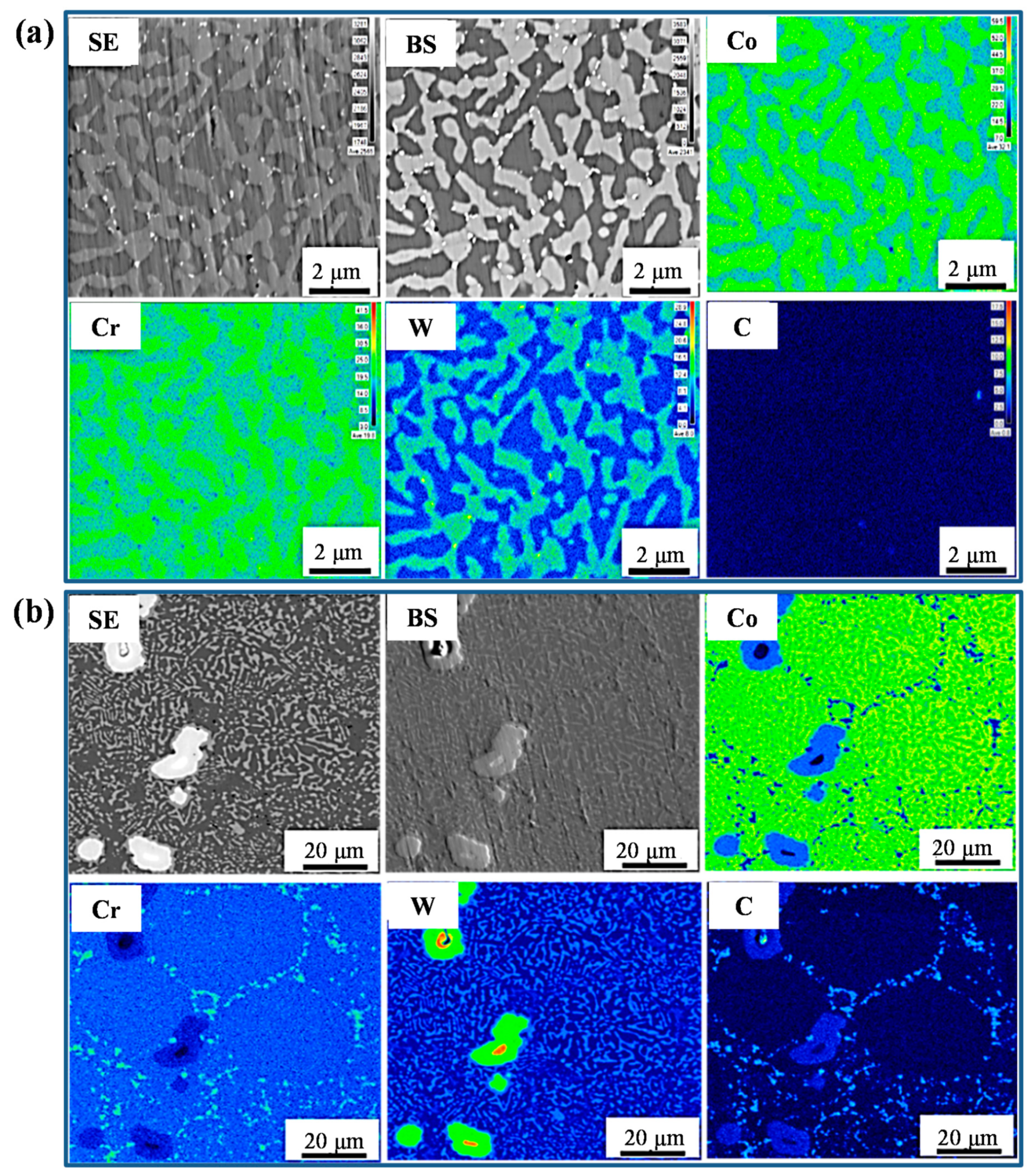
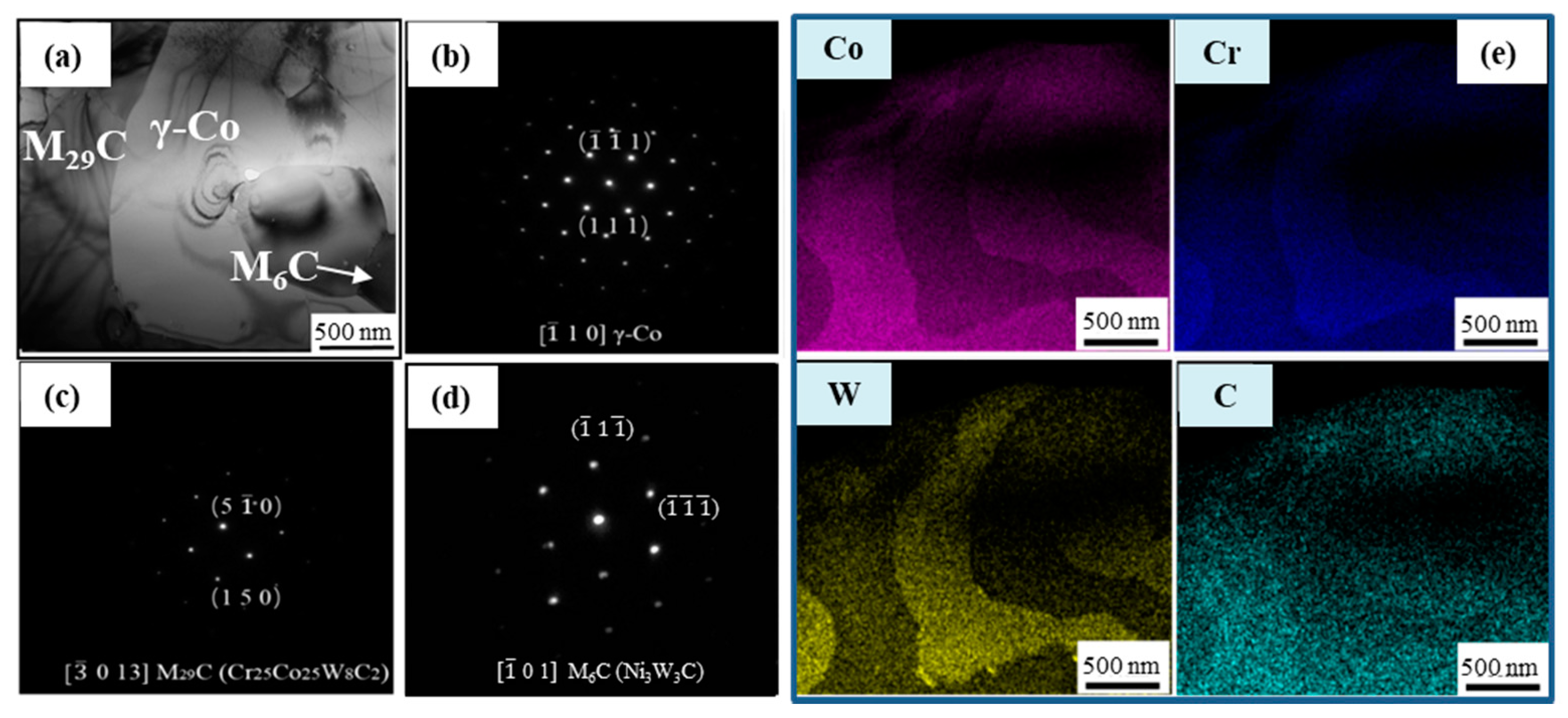
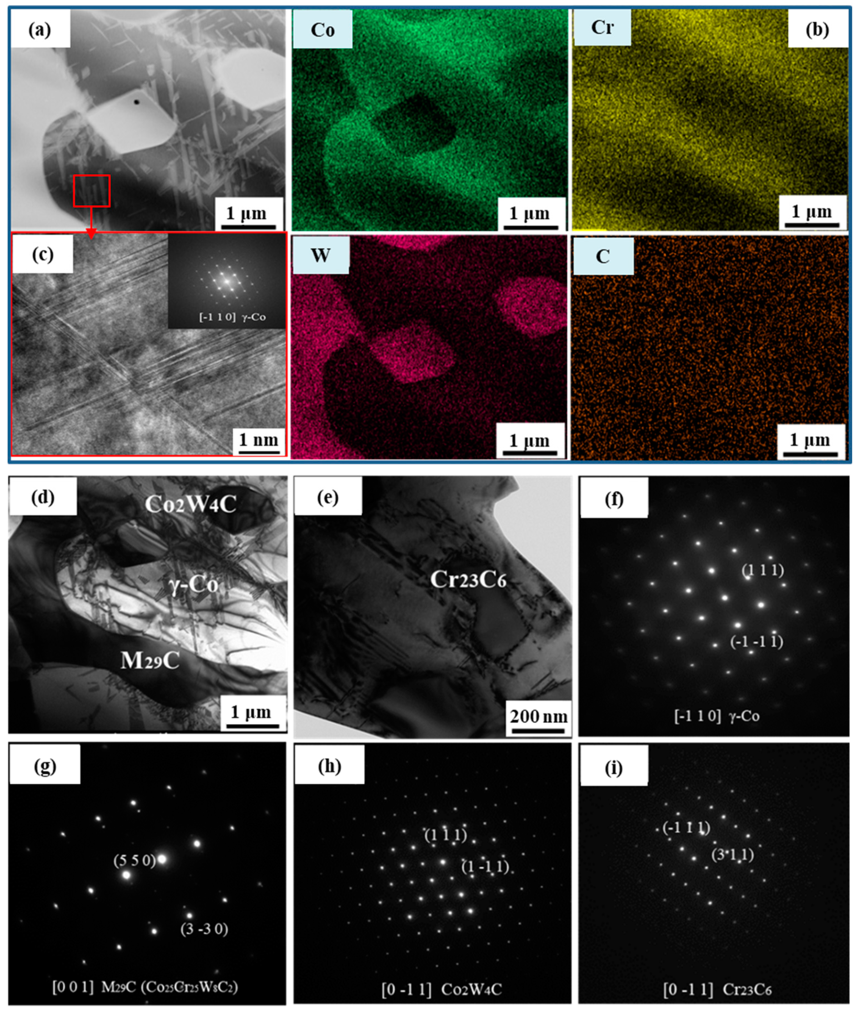
3.2. Microstructure Identification

As the proper sintering temperature is 1150 °C, the microstructures of the Co–Cr–W alloy and Co–Cr–W matrix composites were analyzed with this preparing condition, and the backscattering electron images of the two materials are illustrated in Figure 4. According to the image contrast, there are three and five phases in the Co–Cr–W alloy (Figure 4a,b) and the Co–Cr–W matrix composites (Figure 4c,d), respectively, which are marked by A~C and 1~5, respectively. In the Co–Cr–W alloy, phase-B is dendrite, which is crisscross distributed in the matrix (phase-A). The phase-C is a fine particle, which is distributed at the junction of the phase-A and B. In the Co–Cr–W matrix composites, phase-1 is wrapped by the phase-2. The phase-3 is also dendritic and uniformly distributed in phase-4, and there is a thin layer of gray phase (phase-6) at the boundary of phase-2 and phase-3. The image contrasts of phase-3 and phase-6 are almost the same. In addition, some primary particle boundaries (PPBs) can be observed (Figure 4c,d), and the phase-5 is mainly distributed at the PPBs.
The EPMA elements distribution of the Co–Cr–W alloy and Co–Cr–W matrix composites are shown in Figure 5. The compositions of the micro-areas acquired by the EPMA quantitative analysis are listed in Table 2 and Table 3. In the Co–Cr–W alloy (Figure 5a), phase-A is mainly rich in Co. This indicates phase-A is the matrix, and Cr, Ni, and Fe are the solute elements. Phase-B is mainly rich in Cr and W and contains the higher content of C. This means phase-B is a kind of carbide. The elements enriched in the phase-C are W, Ni, and Cr, and the content of W is very high, and it is inferred to be a W-rich phase. In addition, due to the low content of the C element in the material, there is no obvious C element-rich area. In the Co–Cr–W matrix composites (Figure 5b), Co is uniformly distributed, while W is mainly distributed in the phase-1, phase-2, and phase-3, and the phase-3 has the highest W concentration. The distribution of C and Cr is similar, which are mainly distributed at the PPB (phase-5 is in this region). At the same time, C is also enriched in phase-1 and phase-2. Based on the element distribution and the composition (Table 3) of each phase, it can be inferred the blocky phases (phase-1 and phase-2) are transformed from the added WC particles, and the small particles (phase-5) are generated by the added Cr3C2 particles. The distribution of these phases can further prove this inference. The phase-3 contains Co, Cr, W, and C, and its morphology and composition are similar to that of the phase-B in the Co–Cr–W alloy, so phase-3 and phase-B are inferred to be the same phase. The phase-4 is rich in Co so that it can be identified as the Co-based matrix. The compositions of phase-6 and phase-3 are similar, so phase-6 and phase-3 are inferred to be the same phase.
Figure 6 shows the XRD results of the Co–Cr–W alloy and Co–Cr–W matrix composites. There are three kinds of phases in Co–Cr–W alloy, namely the γ-Co, M6C (Ni3W3C) and M29C (Cr25Co25W8C2), and there are four kinds of phases in the Co–Cr–W matrix composites, namely the γ-Co, M23C6 (Cr23C6), M6C (Co2W4C) and M29C (Cr25Co25W8C2). The result of the Co–Cr–W alloy is consistent with actual observations (Figure 4a,b). However, one phase in the composites is not recognized (five kinds of phases are observed in Figure 4c,d). The reason for this is likely that the content of this phase is too low. In addition, the XRD results cannot identify the specific phases in the two materials, so it needs further experimental verification.
For this, TEM analysis was carried out. In order to make a one-to-one match between the phases in the SEM images and the TEM images, the EDS maps are provided along with the selected area electron diffraction (SAED) patterns. The relevant results are illustrated in Figure 7 and Figure 8. In the Co–Cr–W alloy (Figure 7), the Co-rich region is the phase-A, and the Cr- and W-rich region is the phase-B (Figure 7e). It should be noted that the precision of TEM energy spectrum analysis is slightly lower than that of the EPMA, for the small particle phase (phase-C), the element enrichment cannot be accurately observed, and only some parts of W element enrichment can be seen at the junction of the phase-A and phase-B, which should be the phase-C. Based on this result, the SAED patterns (Figure 7a–d) of the phase-A, phase-B, and phase-C are analyzed. The results indicate phase-A is the γ-Co, phase-B is the M29C, and phase-C is the Ni3W3C. (The phases identified here refer to the phases in the database, which have the same crystal structure.) In the Co–Cr–W matrix composites (Figure 8), the Co-rich region should be the phase-4, and the Cr- and W-rich region is the phase-3 (Figure 8b), which are identified as the γ-Co and the M29C, respectively, by analyzing the SAED patterns (Figure 8f,g). In the TEM bright-field images (Figure 8d,e), another two carbides can be observed. The SAED patterns (Figure 8h,i) indicate they are M6C (Co2W4C) and M23C6 (Cr23C6), respectively. As M6C carbide usually contains a higher content of W [23], phase-2 should be the M6C. Similarly, phase-5 should be the M23C6. It should be pointed out that phase-1 is not observed in the TEM observable field of view. Two reasons may account for this: one is that the content of phase-1 is too low; the other is that the TEM observable field of view is much smaller than that of the SEM. However, phase-1 can be identified according to its composition (Table 3), and it is most likely to be the residual added WC carbides. In addition, the high-angle annular dark field (HAADF) image (Figure 8a) shows there are some stripe-like contrasts in the γ-Co matrix, and the high-resolution electron image (Figure 8c) indicates they are some stacking faults (SFs). This is mainly caused by the low SF energy of Co, and the faults in the Co-based matrix can also reinforce the matrix.

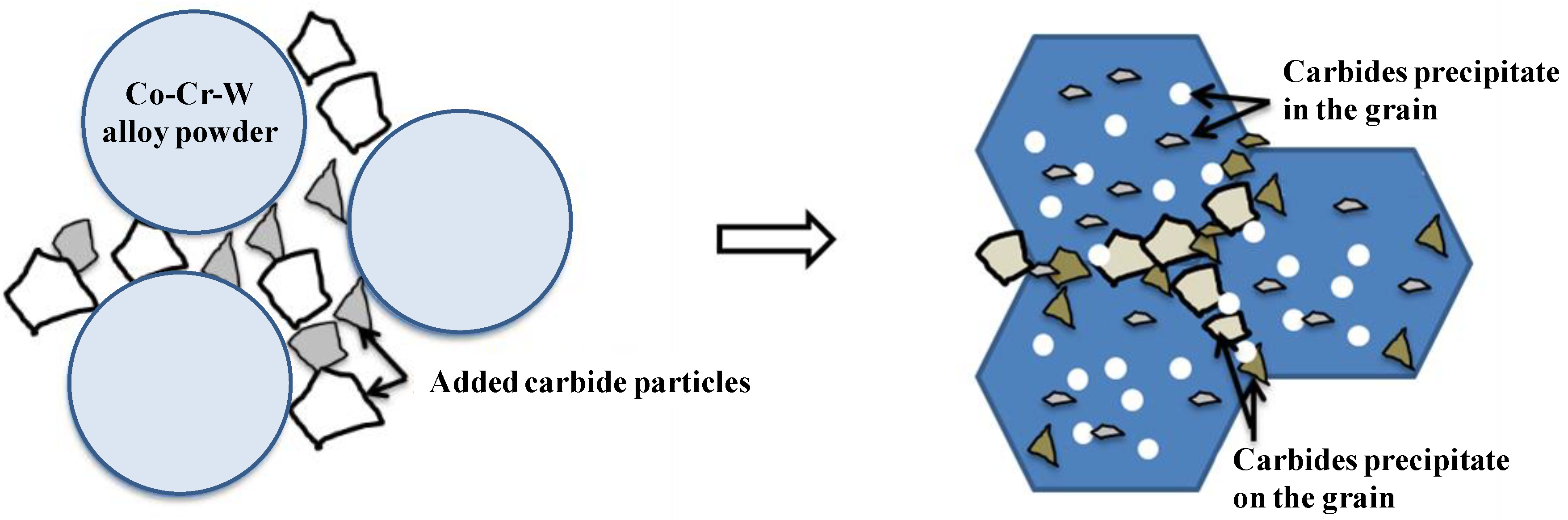
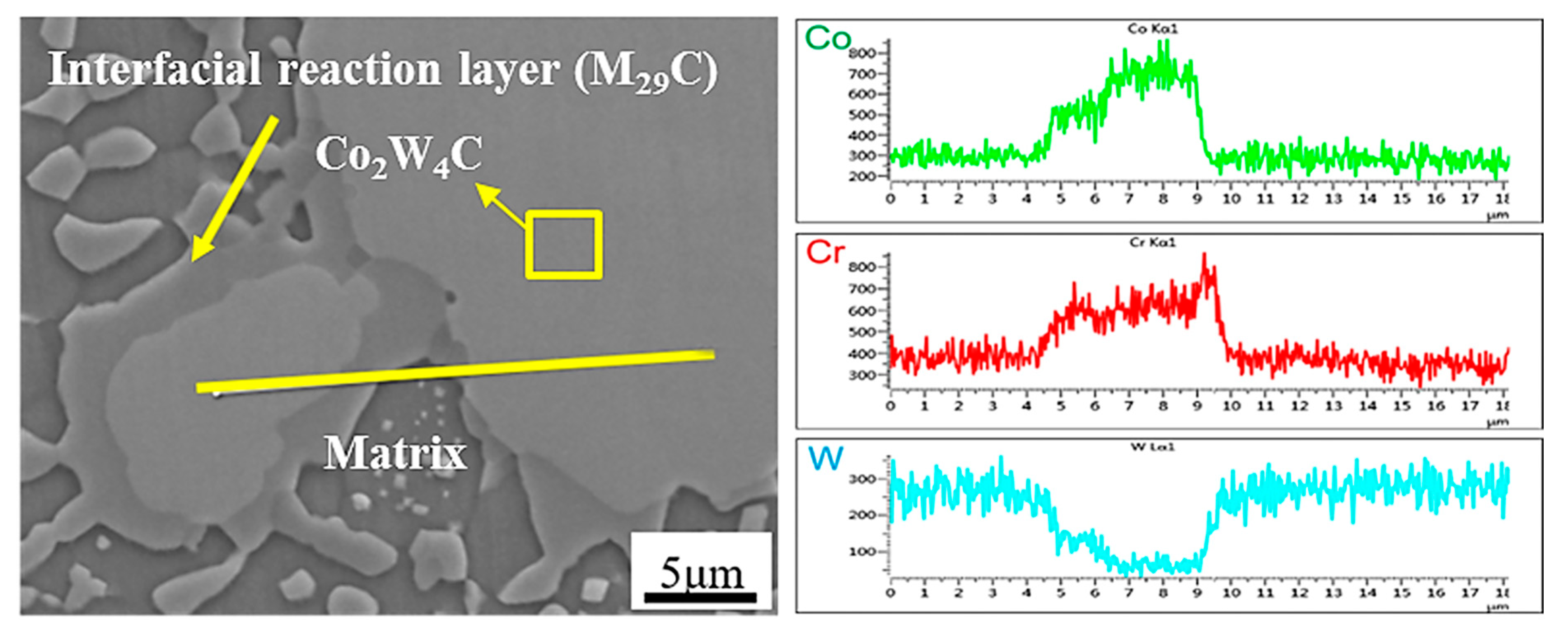
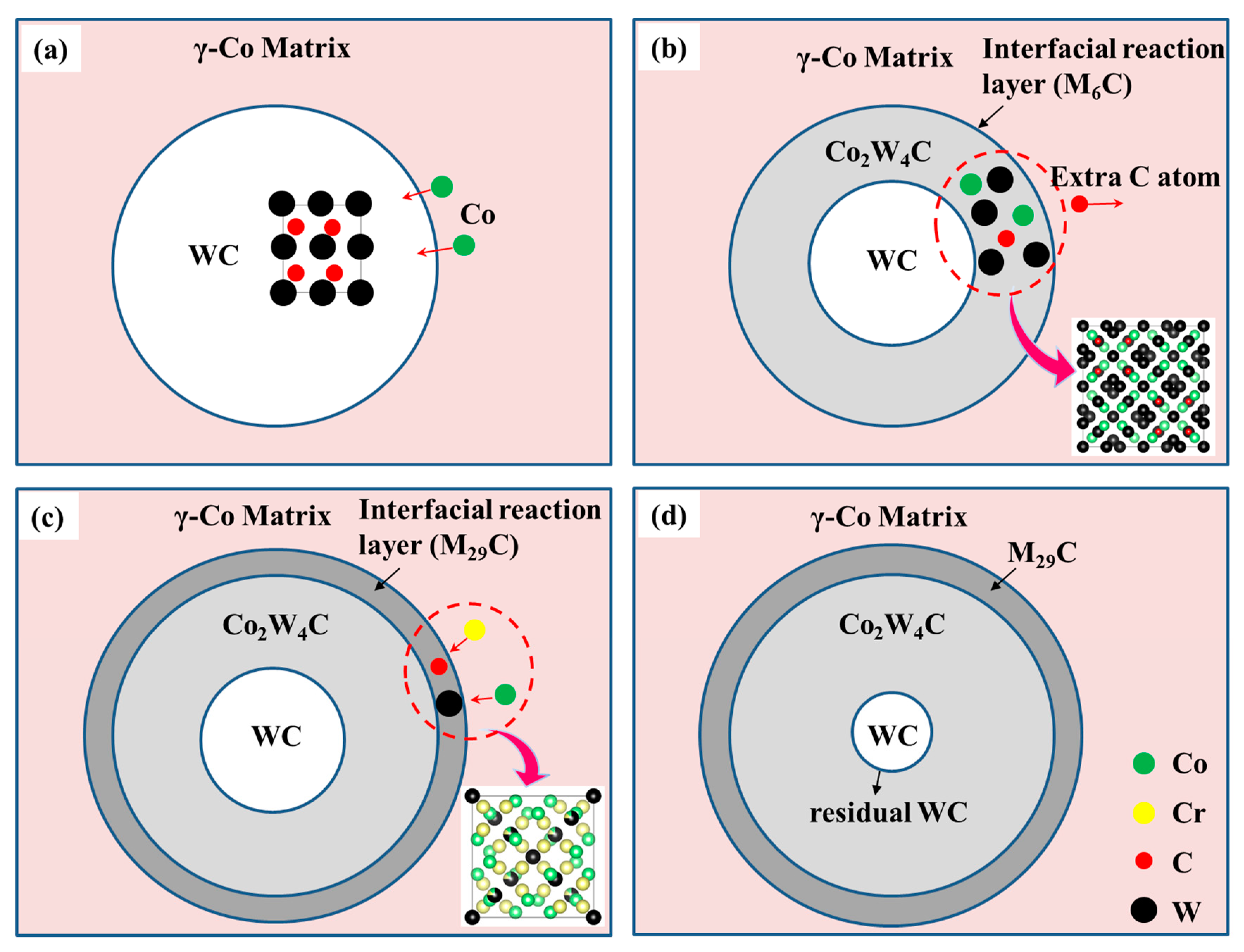
3.3. Formation Mechanisms of the Reinforced Phases

It can be seen from the microstructures of the Co–Cr–W alloy that there are two kinds of reinforced phases, namely the M29C and M6C, and both phases are uniformly distributed in the grains. This proves the two phases are both in situ formed during the hot-pressing sintering process. The formation mechanisms of the M29C and M6C (Ni3W3C) carbides can be understood in this way: first, the W atom has a much larger radius than that of the C, so the diffusion rate of the C in the matrix should be greater than that of the W; secondly, the W element is a strong carbide forming element, so the driving force of the diffusion of C atoms to the W atom rich area is strong. Therefore, the W-rich areas are more likely to form the carbide, and the M29C is thus formed. When the nucleation and growth of the M29C reaches equilibrium, the extra W and C would combine with the Ni and form the Ni3W3C carbide to decrease the system free energy further. In addition, it can be seen from the EPMA results (Table 2) that the Ni atoms tend to converge in the γ-Co rather than the M29C. This means the precipitation of the M29C would expel the Ni atoms, and the Ni atoms tend to combine with the W and C at the grain boundary of the M29C, and this is the reason why most of the Ni3W3C tend to precipitate at the junction of the M29C and γ-Co matrix (Figure 4b). Based on the above discussion, the formation of the M29C and M6C can be illustrated with the following reaction equations:
γ-Co + C → (Ni, W, Cr, Co, Fe)29C
3Ni + 3W + C → Ni3W3C
It has been proven that there are four kinds of carbides in the Co–Cr–W matrix composites, namely the M29C (Cr25Co25W8C2), M23C6 (Cr23C6), M6C (Co2W4C), and WC. As the morphology and distribution of the M29C carbides in the Co–Cr–W alloy and the Co–Cr–W matrix composites are similar, the formation mechanism of the M29C in the two materials should be the same. The M23C6 (Cr23C6), M6C (Co2W4C), and WC are the three carbides that are not contained in the Co–Cr–W alloy. This indicates the formation of the three carbides are all produced by the added carbides (WC and Cr3C2). As the M23C6 contains a higher content of Cr; it distributes at the PPB; the size of it is close to that of the Cr3C2, the M23C6 should be transformed from the Cr3C2, and the reaction equation should be as follows:
3Cr3C2+γ-Co → (Cr, Co, W, Fe)23C6
Similarly, based on the composition, distribution, and size of the Co2W4C, it should be transformed from the WC. Figure 9 shows the EDS line-scan result. It can be seen that the Co and Cr show a gradient rise from the Co2W4C to the γ-Co matrix. This indicates the Co and Cr atoms diffuse from the matrix to the added reinforced phase (WC) and react at the boundary of the reinforced phase to form the Co2W4C. From the reinforced phase to the matrix, the content of the W gradually decreases, and there is almost no element W in the matrix. This indicates the W in the carbide does not diffuse into the matrix. Figure 10 shows the schematic of the formation mechanism of the carbides. In the hot-pressing sintering process, the Co atoms would diffuse into the WC and react with the WC, which leads to the formation of the M6C (Figure 10a,b). Then, the reaction remaining C atoms would diffuse into the nearby matrix and react with the Cr, Co, and W atoms to form the M29C (Figure 10c), and this is why the Co2W4C is surrounded by the M29C. In addition, if the holding time is insufficient, the WC could not react adequately, and there will be some WC left in the Co2W4C (Figure 10d). Therefore, the WC can be observed in the M6C (Figure 4c). Based on the above analysis, the reaction of the WC and the γ-Co can be illustrated with the following equation:
2WC + γ-Co→(W, Co, Cr, Fe)6C + (Ni, W, Cr, Co, Fe)29C
In addition, it should be noted there are not any Ni3W3C carbides in the Co–Cr–W matrix composites, which are observed in the Co–Cr–W alloy (Figure 4). This indicates the added reinforced phases inhibit the precipitation of this carbide. As the result shows, the precipitation of the Ni3W3C consumes the W element in the matrix, this means if there is a phase that can preferentially consume the W element, then the phase can inhibit the precipitation of the Ni3W3C. According to Figure 4c, the size of the Co2W4C is more than 10 μm, while the original particle size of WC is less than 10 μm. This indicates the Co2W4C could grow towards the matrix in the hot-pressing process, and it can consume not only the W element in the WC but also consume the W element in the matrix. In addition, based on the Materials Project database [24], the formation energy of the Co2W4C is −0.067 eV, and the formation energy of the Ni3W3C is −0.033 eV. This means the Co2W4C is easier to form in the view of thermodynamics. Therefore, it can be inferred the precipitation of the Co2W4C inhibits the precipitation of the Ni3W3C.
Based on the above discussion, the reinforced carbides in the Co–Cr–W matrix composites have two formation mechanisms: one is the in situ endogenous mechanism by phase transformation; the other is in situ exogenous mechanism by the reaction. This could make the composites have not only the intragranular strengthening but also the grain boundary strengthening.
Figure 9. EDS line-scan result from the Co2W4C to the matrix in the Co–Cr–W matrix composites.
Crystals 12 00198 g009
Figure 10. Schematic showing the formation mechanism of carbides in the Co–Cr–W matrix composites. (a) Diffusion of Co atoms to the added WC; (b) reaction of the Co with the WC and formation of the M6C; (c) the reaction remaining C atoms diffuse into the matrix and react with the W, Cr and Co atoms to form the M29C; (d) underreaction of the WC lead to the formation of the residual WC in the M6C.
Crystals 12 00198 g010

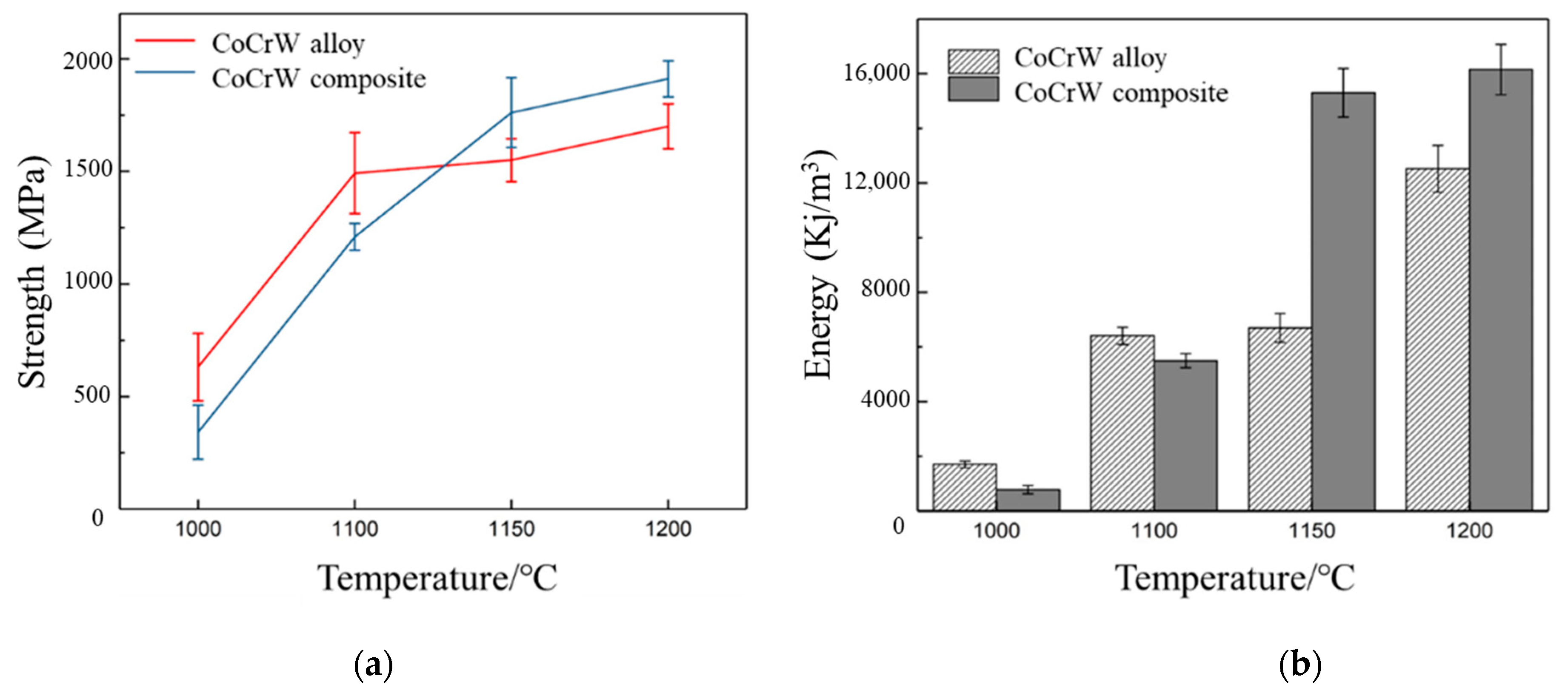
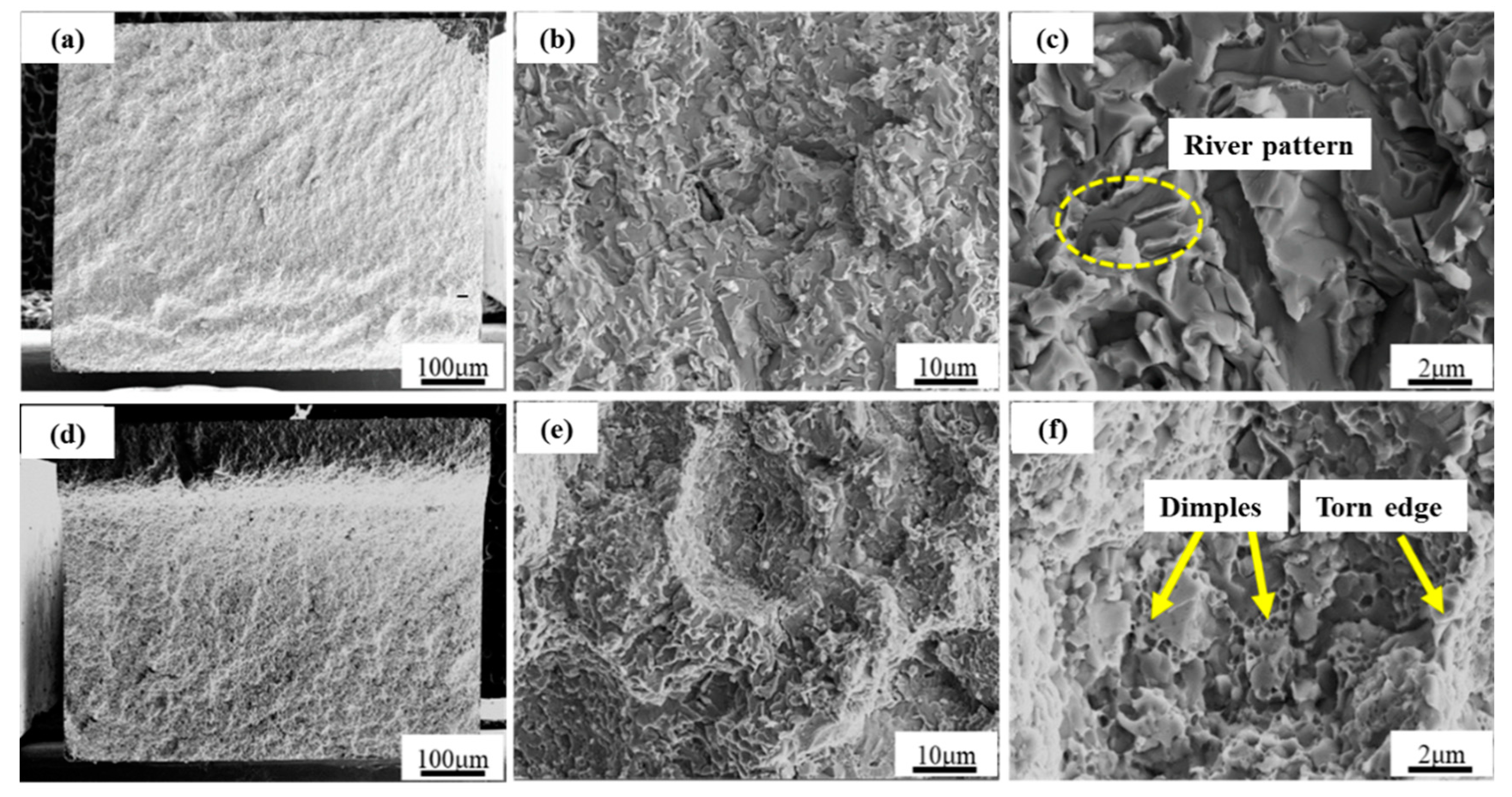
3.4. Mechanical Property

Figure 11 shows the three-point bending experiment results of the Co–Cr–W alloy and Co-Cr-W matrix composites at different sintering temperatures. The bending strengths and of the two materials increase with the increase of the sintering temperature (Figure 11a). This is because increasing the sintering temperature can improve the compactness of the two materials (Figure 3). However, the increasing rates of the two materials are different. When the sintering temperature is below 1150 °C, the bending strength of the Co–Cr–W alloy is higher, while when the sintering temperature is over 1150 °C, the bending strength of the Co–Cr–W matrix composites are higher.
The reason for this should be that the compactness of the two materials is very low at the low sintering temperature, and the reinforced phases are not well combined with the matrix. Thus, the reinforced phases do not enhance the composites, and on the contrary, it is equivalent to introducing impurities into the material, resulting in the bending strength of the composite material being lower than that of the pure alloy. However, when the sintering temperature is high, both materials are fully sintered, and the M23C6 and M6C carbide at the PPB are closely bonded with the matrix material, which can strengthen the grain boundary to a certain extent. In addition, the toughness of the two materials has the same trend as the bending strength with the increase of sintering temperature (Figure 11b). This is not only related to the compactness but also the strength of the matrix of the composites. As the result shows, the addition of the reinforcing phases would make the solid solution elements (W, Ni, and Cr) in the matrix diffuse to the added reinforced phases, which can reduce the strength and improve the plasticity of the matrix, and finally lead to the improvement of the toughness of the composites. According to the fracture of the two materials, it proves that the fracture of the Co–Cr–W alloy is cleavage fracture which is characterized by river pattern (Figure 12a–c), and the composites display the fracture features of the dimple fracture (Figure 12d–f). The results indicate the multi-scale reinforced phases added to the sintered composites can effectively improve the bending strength and toughness.

4. Conclusions

(1)
With the increase of the hot-pressing sintering temperature, the element diffusion in the material becomes sufficient, leading to the denser microstructure of the Co–Cr–W alloy and the composite materials;
(2)
The Co–Cr–W alloy is composed of the γ-Co matrix, the M6C (Ni3W3C) carbide particles, and the dendritic M29C (Cr25Co25W8C2) carbide, and the main reinforced phase is the M29C; the Co–Cr–W matrix composites are composed of the γ-Co matrix, the M23C6 (Cr23C6) carbide particles, the blocky M6C (Co2W4C) carbide and the dendritic M29C (Cr25Co25W8C2);
(3)
At the proper hot-pressing sintering temperature, the added reinforced phases in the Co–Cr–W matrix composites can react with the matrix and form a good bonding interface, which can strengthen the grain boundary;
(4)
The prepared Co–Cr–W matrix composites have the multi-scale carbide strengthening effect, namely the dendritic M29C strengthens the grain and the M23C6 and M6C strengthen the grain boundary, which makes the composites have greater bending strength and toughness than the pure Co–Cr–W alloy.

Author Contributions

Conceptualization, S.W. and S.Z.; methodology, S.Z. and X.H.; validation, L.W., H.Z. (Zhang Hongwei) and H.Z. (Zhang Hongyu); formal analysis, L.W.; investigation, S.W.; resources, Y.S. and L.H.; data curation, S.Z.; writing—original draft preparation, S.W.; writing—review and editing, S.W.; visualization, S.W.; supervision, S.W.; project administration, L.H.; funding acquisition, Y.S. All authors have read and agreed to the published version of the manuscript.

Funding

This research was funded by National Natural Science Foundation of China under Grant (No. 51801206) and National Science and Technology Major Project under Grant (No. J2019-VI-0018-0133), and Key Specialized Research and Development Breakthrough–unveiling and commanding the special project program in Liaoning province under Grant (No. 2021JH15).

Data Availability Statement

Not applicable.

Acknowledgments

We are also grateful to J.Y. Pang and H.L. Zhang for transmission electron microscope technical support.

Conflicts of Interest

The authors declare no conflict of interest.

References

  1. Liu, R.; Yao, J.H.; Zhang, Q.L.; Yao, M.X.; Collier, R. Microstructures and Hardness/Wear Performance of High-Carbon Stellite Alloys Containing Molybdenum. Metall. Mater. Trans. A 2015, 46, 5504–5513. [Google Scholar] [CrossRef]
  2. Dilawary, S.; Motallebzadeh, A.; Paksoy, A.H.; Afzal, M.; Atar, E.; Cimenoglu, H. Influence of laser surface melting on the characteristics of Stellite 12 plasma transferred arc hardfacing deposit. Surf. Coat. Technol. 2017, 317, 110–116. [Google Scholar] [CrossRef]
  3. Rong, L.; Yao, J.; Zhang, Q.; Yao, M.X.; Collier, R. Effects of molybdenum content on the wear/erosion and corrosion performance of low-carbon Stellite alloys. Mater. Des. 2015, 78, 95–106. [Google Scholar] [CrossRef]
  4. Yamanaka, K.; Mori, M.; Kuramoto, K.; Chiba, A. Development of new Co–Cr–W-based biomedical alloys: Effects of microalloying and thermomechanical processing on microstructures and mechanical properties. Mater. Des. 2014, 55, 987–998. [Google Scholar] [CrossRef]
  5. Lu, Y.; Xu, X.; Yang, C.; Ren, L.; Luo, K. In vitro insights into the role of copper ions released from selective laser melted CoCrW-xCu alloys in the potential attenuation of inflammation and osteoclastogenesis. J. Mater. Sci. Technol. 2020, 41, 58–69. [Google Scholar] [CrossRef]
  6. Miyake, M.; Matsuda, T.; Sano, T.; Hirose, A.; Sasaki, M. Microstructure and mechanical properties of additively manufactured CoCrW alloy using laser metal deposition. Weld. World Le Soudage Dans Le Monde 2020, 64, 1397–1407. [Google Scholar] [CrossRef]
  7. He, B.; Nie, Q.; Zhang, H.; Wei, H. Effects of solution treatment on microstructure and wear-resistant properties of cocrw alloys. Acta Met. Sin. 2016, 52, 484–490. [Google Scholar] [CrossRef]
  8. Peng, H.S. Study on Microstructure and Properties o f Co–Cr–W Alloy Prepared by Powder Metallury. Master’s Thesis, Lanzhou University of Technology, Lanzhou, China, 2016; pp. 23–27. [Google Scholar]
  9. Yan-Hong, L.V.; Zhang, Q.F.; Zi-Jian, W.U. Extended Behavior of Crack During Thermal Shock Testing of HVOF Sprayed CoCrW Coatings. China Surf. Eng. 2015, 28, 81–87. [Google Scholar] [CrossRef]
  10. Lu, Y.; Wu, S.; Gan, Y.; Li, J.; Zhao, C.; Zhuo, D.; Lin, J. Investigation on the microstructure, mechanical property and corrosion behavior of the selective laser melted CoCrW alloy for dental application. Mater. Sci. Eng. C 2015, 49, 517–525. [Google Scholar] [CrossRef] [PubMed]
  11. Nadolski, M.; Golański, G.; Klimas, J.; Szota, M.; Szymański, J. Microstructure And Functional Properties of Prosthetic Cobalt Alloys CoCrW. Arch. Met. Mater. 2015, 60 Pt A, 1999–2003. [Google Scholar] [CrossRef] [Green Version]
  12. Xin, X.-Z.; Chen, J.; Xiang, N.; Wei, B. Surface Properties and Corrosion Behavior of Co–Cr Alloy Fabricated with Selective Laser Melting Technique. Cell Biochem. Biophys. 2013, 67, 983–990. [Google Scholar] [CrossRef] [PubMed]
  13. Lu, Y.; Guo, S.; Yang, Y.; Liu, Y.; Zhou, Y.; Wu, S.; Zhao, C.; Lin, J. Effect of thermal treatment and fluoride ions on the electrochemical corrosion behavior of selective laser melted CoCrW alloy. J. Alloys Compd. 2018, 730, 552–562. [Google Scholar] [CrossRef]
  14. Wang, S.Y.; Hou, X.Y.; Wang, L.; Zhang, H.Y.; Zhang, W.B.; Xia, Y.P.; Sun, Y.; Zhou, Y.Z. Effect of ball-milling process in combination with the addition of carbide microparticles on the microstructure and wear resistance of a Co–Cr–W alloy prepared by powder metallurgy method. Mater. Res. Express 2021, 8, 066506. [Google Scholar] [CrossRef]
  15. Luo, J.; Wu, S.; Lu, Y.; Guo, S.; Yang, Y.; Zhao, C.; Lin, J.; Huang, T.; Lin, J. The effect of 3wt.% Cu addition on the microstructure, tribological property and corrosion resistance of CoCrW alloys fabricated by selective laser melting. J. Mater. Sci. Mater. Med. 2018, 29, 37. [Google Scholar] [CrossRef]
  16. Wang, G.G.; You, X.H.; Wang, J.; Tao, Y.U.; Jian-Hui, L.I.; Zhang, Z.Y. Microstructure and Mechanical Properties of As-cast and Hot-pressed CoCrW Alloys. Foundry Equip. Technol. 2015, 37–40. [Google Scholar]
  17. You, X.; Wang, G.; Wang, J.; Xu, T.; Wei, H. Effect of Solid Solution Treatment Onmicrostructure and Mechanicalproperties of Hot-Press CoCrW Alloys. Acta Met. Sin. 2016, 52, 161–167. [Google Scholar]
  18. Liang, J.K.; Hou, X.Y.; Cui, Y.; Zhang, H.Y.; Jin, T. Effect of sintering temperature on microstructures and mechanical properties of Co-based wear-resistant alloy. Fenmo Yejin Jishu/Powder Metall. Technol. 2017, 35, 188–194. [Google Scholar] [CrossRef]
  19. Abbas, G.; West, D. Laser surface cladding of stellite and stellite-SiC composite deposits for enhanced hardness and wear. Wear 1991, 143, 353–363. [Google Scholar] [CrossRef]
  20. Zhong, M.L.; Liu, W.J. Microstructure Evolution of Stellite 6+Wcby High Power Laser Cladding. Acta Met. Sin. 2002, 38, 495–500. [Google Scholar] [CrossRef]
  21. Xiong, Y.; Wang, Y.; Zhang, K.F.; Zhang, G.Q. Microstructures and Properties of Laser Cladding Stellite6/WC. China Surf. Eng. 2008, 21, 37–40. [Google Scholar] [CrossRef]
  22. An, Q.; Huang, L.J.; Bao, Y.; Zhang, R.; Jiang, S.; Geng, L.; Xiao, M. Dry sliding wear characteristics of in-situ TiBw/Ti6Al4V composites with different network parameters. Tribol. Int. 2018, 121, 252–259. [Google Scholar] [CrossRef]
  23. Inoue, A.; Masumoto, T. Carbide reactions (M3C → M7C3 → M23C6 → M6C) during tempering of rapidly solidified high carbon Cr–W and Cr-Mo steels. Metall. Trans. A 1980, 11, 739–747. [Google Scholar] [CrossRef]
  24. Materials Project Database. Available online: https://materialsproject.org/ (accessed on 20 November 2021).
Figure 1. Schematic of the microstructure of the alloy prepared by introducing the reinforced carbides [14].
Crystals 12 00198 g001
Figure 2. SEM images of Co–Cr–W alloy powder and carbide powder. (a) Co–Cr–W alloy powder; (b) Cr3C2 powder; (c) WC powder.
Crystals 12 00198 g002
Figure 3. SEM images of the Co–Cr–W alloy and the Co–Cr–W matrix composites with different sintering temperature. (ad) Co–Cr–W alloy; (eh) Co–Cr–W matrix composites; (a,e) 1000 °C; (b,f) 1100 °C; (c,g) 1150 °C; (d,h) 1200 °C.
Crystals 12 00198 g003
Figure 4. Backscattered electron images of the Co–Cr–W alloy and the Co–Cr–W matrix composites. (a,b) Co–Cr–W alloy; (c,d) Co–Cr–W matrix composites.
Crystals 12 00198 g004
Figure 5. The element distribution maps of a micro-area of the Co–Cr–W alloy and the Co–Cr–W matrix composites. (a) Co–Cr–W alloy; (b) Co–Cr–W matrix composites.
Crystals 12 00198 g005
Figure 6. XRD patterns of the Co–Cr–W alloy and the Co–Cr–W matrix composites. (a) Co–Cr–W alloy; (b) Co–Cr–W matrix composites.
Crystals 12 00198 g006
Figure 7. (a) TEM bright-field image of the Co–Cr–W alloy; (bd) Selected area electron diffraction (SAED) patterns of γ-Co (b), M29C (c), and M6C (d); (e) and EDS maps performed on a micro-area.
Crystals 12 00198 g007
Figure 8. (a) HAADF images showing the precipitates in the Co–Cr–W matrix composites; (b) displaying the related EDS mapping results; (c) high-resolution electron image of the γ-Co phase; (d,e) bright-field image showing the precipitates in the Co–Cr–W matrix composites; (fi) SAED patterns of the related phases.
Crystals 12 00198 g008
Figure 11. Results of the three-point bending experiment. (a) The bending strength of the Co–Cr–W alloy and the composites; (b) the toughness statistical diagram of the Co–Cr–W alloy and the composites.
Crystals 12 00198 g011
Figure 12. Bending fracture of the Co-Cr-W alloy and composite materials. (ac) The Co–Cr–W alloy; (df) the Co–Cr–W matrix composites.
Crystals 12 00198 g012
Table 1. Chemical compositions of Co-Cr-W alloy powder (wt.%).
ElementsCrWNiVFeCCo
Co–Cr–W30~3218~203~43~53~40.2~0.8Bal.
Table 2. The EPMA result (In the result, C is a light element and cannot be precisely measured by the EPMA. Therefore, the result is semi-quantitative for the C element.) of phases in the pure Co–Cr–W alloy (at. %).
Element
Position
CrCoWFeNiVCPhase
A36.352148.64851.92064.99695.00360.01201.35215γ-Co
B42.474333.650713.650400.23700.03843.6116M29C
C21.523912.368124.31642.258830.120709.0615M6C
Table 3. The EPMA result of phases in the Co–Cr–W matrix composites (at. %).
Element
Position
CrCoWFeNiVCPhase
12.86483.326549.497100.1670.01243.2621WC
221.700725.067535.60682.25881.44240.038413.6116M6C
337.523942.684413.98521.65061.903602.2523M29C
432.285554.81593.88493.23694.120701.6526γ-Co
551.664413.36813.92061.99690.96530.038213.5808M23C6
636.474339.650713.50842.11151.810302.0615M29C
Publisher’s Note: MDPI stays neutral with regard to jurisdictional claims in published maps and institutional affiliations.

