Article

Experimental Analysis of Polycaprolactone High-Resolution Fused Deposition Manufacturing-Based Electric Field-Driven Jet Deposition

1
College of Mechatronics, Xuchang University, Xuchang 461000, China
2
State Key Laboratory of High Performance Complex Manufacturing, Central South University, Changsha 410083, China
3
State Key Laboratory of Mechanical Transmission, Chongqing University, Chongqing 400044, China
4
SINOMACH Industrial Internet Research Co., Ltd., Zhengzhou 450007, China
*
Authors to whom correspondence should be addressed.
Crystals 2022, 12(11), 1660; https://doi.org/10.3390/cryst12111660
Submission received: 2 October 2022 / Revised: 8 November 2022 / Accepted: 15 November 2022 / Published: 18 November 2022

Abstract

:
Polycaprolactone (PCL) scaffolds have been widely used in biological manufacturing engineering. With the expansion of the PCL application field, the manufacture of high-resolution complex microstructure PCL scaffolds is becoming a technical challenge. In this paper, a novel PCL high-resolution fused deposition 3D printing based on electric field-driven (EFD) jet deposition is proposed to manufacture PCL porous scaffold structures. The process principle of continuous cone-jet printing mode was analyzed, and an experimental system was constructed based on an electric field driven jet to carry out PCL printing experiments. The experimental studies of PCL-fused deposition under different gas pressures, electric field voltages, motion velocities and deposition heights were carried out. Analysis of the experimental results shows that there is an effective range of deposition height (H) to realize stable jet printing when the applied voltage is constant. Under the stretching of electric field force and viscous drag force (FD) with increasing movement velocities (Vs) at the same voltage and deposition height, the width of deposition lines was also gradually decreased. The width of the deposition line and the velocity of the deposition platform is approximately a quadratic curve. The bending phenomenon of deposition lines also gradually decreases with the increase of the movement velocities. According to the experiment results, a single layer linear grid structure was printed under the appropriate process parameters, with compact structure, uniform size and good straightness. The experimental results verify that the PCL porous scaffold structure can be accurately printed and manufactured.

1. Introduction

The importance of micro (μ) and nano (η) scale manufacturing as research subjects has increased worldwide in both academia and industry [1]. The traditional micro/nano manufacturing technology mainly includes micro-electrical discharge machining (EDM) [2], nano-lithography [3], high-speed micro-milling, Lithographie, Galvanoformung and Abformung (LIGA) technology [4], micro/nano embossing [5], and other micro/nano manufacturing technologies. Such technologies are generally applied to fabricate simple 2D micro/nano geometries and are unable to manufacture complex and multi-material 3D structures on the micro/nano scale [6].
Micro/nano 3D printing technology is a new micro/nano manufacturing method based on the principle of additive manufacturing. It can directly print and form structures with minimum feature sizes, ranging from tens of nanometers to several microns [7].
At present, the micro-nano 3D printing technologies mainly include: two-photon polymerization (TPP) [8], electrohydrodynamic (EHD) jet printing [9], laser-induced forward transfer (LIFT) [10], electrochemical deposition [11], aerosol jet (AJ) deposition [12], projection microstereolithography (PμSL) [13], and focused electron beam (FEB) -induced deposition [14]. Micro/nano 3D printing technologies have been applied to micro actuators [15], micro-electro-mechanical systems, micro batteries/supercapacitors [16], microfluidic chips, micro/nano-optics [17], and multi-scale bio-active scaffolds [18].
With the development of biological tissue engineering, biological scaffolds are regarded as one of the most effective therapeutic methods in biomedicine [19]. Polycaprolactone (PCL) is a chemically synthesized, colorless crystalline solid polymer with a low molecular weight. PCL has good biocompatibility, biodegradability, drug permeability, high crystallization and a low melting point [20]. Biological cells can grow normally on their substrates and can be degraded into CO2 and H2O. PCL has been applied to sustained-release drug carriers, cell tissue culture scaffolds, degradable surgical sutures without removal, high-strength environmental protection film products, plasticizers for nanofiber spinning, low-temperature impact of plastic, medical modeling materials and toys, etc. [21,22,23].
In recent years, with the continuous expansion of the application field of PCL, the demand for the manufacture of high-resolution complex microstructure PCL scaffolds is increasing. At present, PCL structures can be processed by traditional injection molding, casting molding, extrusion molding, hot molding and other methods. However, the existing processing technology has poor dimensional precision and shape controllability, a high production cost and a long manufacturing cycle. There are some limitations to the forming of high-resolution and complex microstructures, so it is urgent to develop new high-resolution forming technology for PCL.
Additive manufacturing technology (ISO/ASTM 52900: 2021), which applies the additive shaping principle and thereby builds physical three-dimensional (3D) geometries through the successive addition of material [24], provides an entirely new solution for PCL processing, which is considered one of the top 12 disruptive technologies that will determine the future of the economy. Compared with the traditional material removal and cutting technology, additive manufacturing technology does not need tools, fixtures and molds, and can quickly and precisely manufacture parts with arbitrary complex shapes, which can significantly reduce the processing procedures, shorten the product opening cycle and reduce the cost input. Additive manufacturing is a powerful tool for the aerospace industry. According to Wohler’s Report 2022, the global additive manufacturing market scale reached $15.244 billion in 2021, and additive manufacturing technology has been widely applied in aerospace, medical, automotive, consumer/electronic products, scientific research institutions, energy, government/military, construction and other fields [25,26]. At present, the additive manufacturing technologies used in tissue engineering mainly include fused deposition modeling (FDM) [27,28] and direct ink writing (DIW) [29], stereo lithography apparatus (SLA) [30], selected laser sintering [31], etc. The effects of fused filament fabrication (FFF) process parameters on mechanical and surface properties of Nylon 6/66 copolymer was analyzed [32]. The orientation effect in as-printed and as-sintered bending properties fabricated by metal-fused filament fabrication was researched [33]. A transient thermal finite-element analysis model of the fused filament fabrication process was built [34].
Jiao et al. [35] used FDM technology to fabricate nano-hyaluronic HA/PCL biological scaffolds. However, the larger fiber diameter (400 μm) makes it difficult for cells to attach, and the pore diameter is much larger than the cell diameter. Cells can only proliferate and differentiate along the path where the fiber is located, and the speed is slow, which cannot achieve the desired effect of cell culture. He et al. [36] used DIW technology to fabricate hydrogel biological scaffolds and studied the diffusion and deposition of hydrogels in different printing cycles. However, DIW technology is limited by the printing material and the printing line width (600 μm). The printing line width is thick, the cell adhesion is poor, the printed biological scaffolds collapse seriously, and the connectivity rate between pores is poor, which hinders the cell adhesion and the circulation of nutrients. Lu et al. [37] used SLA technology to fabricate calcium silicate bioceramic scaffolds with pores of different shapes. This technology has a high printing resolution (20 μm), a smooth sample surface and a fast printing speed, but the photoinitiator and residual resin may have a potential toxicity. Although the aforementioned printing technologies can achieve the rapid prototyping of biological scaffolds, these technologies also have problems such as low printing resolution, thick fiber diameter, large pore size, and toxicity, which cannot reach the microenvironment needed for cell survival.
In order to achieve the microenvironment needed for cell survival and meet the requirements of highly porous and high pore connectivity, Researchers also proposed novel printing technologies such as near-field electrospinning (NFES) [38,39] and melt electrospinning writing (MEW) [40,41,42]. By reducing the deposition height and controlling the stability of the jet, the micro and nano fibers were successfully deposited, and the biological scaffolds more consistent with the characteristic size of cells were prepared. He et al. [43] used NFES technology to fabricate PCL and hydroxyphosphate ash with different content of hydroxyapatite (HAP) composite biological scaffolds (the average pore size was 167 μm) and cell experiments were carried out. Eichholz et al. [44] used MEW technology to fabricate PCL biological scaffolds, conducted biocompatibility experiments, prepared biological scaffolds with different structures, and explored the influence of biological scaffold structure on cell morphology. Hryneevich et al. [45] used MEW technology to fabricate PCL biological scaffolds (pore size is 50 μm) and conducted biocompatibility experiments. The relationship between fiber diameter and printing speed and back pressure under the same voltage was studied. Kan et al. [46] used electrospinning technology to fabricate the Core-Shell PVA–PEG–SiO2@PVA–GO Fiber Mats, and the shell wall thickness and core were near 66 ± 18 nm and 173 ± 25 nm, respectively.
While the above electrospinning process can print scaffolds for the microenvironment in which cells live, the printing process needs to ensure that the nozzle and deposition substrate are conductive material, that the positive electrode of the high voltage needs to be connected to the nozzle, and that the negative electrode needs to be connected to the deposition substrate and an electric field forms between them. The distance between the nozzle and the substrate is limited to a very small range of dimensions. With the increase of the height of the printing structure, the voltage needs to continue to increase, with the forming height limit. On the other hand, due to the presence of residual charges in the stacking fibers, when the printed distance is very small, adjacent fibers will fuse together or have repulsive reactions, which cannot achieve accurate fiber deposition.
In order to solve the current technical problems, a novel high-resolution PCL-fused deposition 3D print based on electric field-driven (EFD) jet deposition [47,48,49] is proposed to manufacture PCL porous scaffold structures. The EFD technology, based on an electrostatic induction self-excited electric field, only needs the positive electrode of the high voltage power supply to be connected to the nozzle. The process principle of the continuous cone-jet printing mode was analyzed and PCL printing experiments were carried out. A single layer linear grid structure with a compact structure, uniform size and good straightness was printed.

2. Process Principle

EFD continuous cone-jet deposition technology is a novel, micro-scale 3D printing technology, which is based on an electrostatic induction self-excited electric field. The printing modes can be divided into a pulsed cone-jet mode and a continuous cone-jet mode. High viscosity materials can be efficiently printed using the continuous cone jet mode under the premise of meeting the required accuracy. A high-voltage DC is used as the driving signal in the continuous cone-jet mode. Figure 1 shows the principle of continuous cone-jet deposition based on a high-voltage-driven electric field.
The forming principle is as follows: a meniscus shape of high viscosity liquid material is produced at the bottom of the nozzle under the action of gravity and air pressure. The conducting nozzle is connected to the positive electrode of the high-voltage DC power supply so that it has a high potential. The meniscus shape liquid surface has the positive charges.
When the Z moving platform drives the printing nozzle close to the deposition substrate, the positively charged nozzle will interact with the substrate. Electrostatic induction will be generated between the printing nozzle and the deposition substrate, resulting in charge redistribution inside the substrate. Negative charges will be attracted to the upper surface of the substrate facing the nozzle, while positive charges will be distributed on the lower surface of the substrate far away from the nozzle, as shown in Figure 1.
The change of charge position will change the original electric field distribution, and the electric field between the print nozzle and the target substrate will be enhanced by the negative charge attracted by the upper surface of the substrate. Under the combined effects of electric field force, surface tension, viscous force and air pressure, the curved liquid surface at the bottom of nozzle is gradually elongated to form a Taylor cone. Once the electric field force (including: FN-normal electric field force, FT-tangential electric field force, FP-polarization electric field force) exceeds the liquid surface tension (FS) and viscous force (FV), the positively charged liquid is ejected from the top of the Taylor cone, forming a very fine cone jet.
When the continuous fine cone jet is deposited on the substrate, with the rapid movement of the deposition substrate, a viscous dragging force (FD) is generated on the printing material, which further stretches and narrows the micro jet to form the microfilament. The diameter of the jet is usually less than one tenth of the nozzle diameter. In this process, the DC high-voltage power provides a continuous and stable electric field force for the printing melt to ensure the continuous jet injection. Combined with the back pressure, voltage and platform moving speed and other process parameters, the size effect of the microfiber is further reduced through the viscous dragging force, and the continuous and stable printing molding of higher resolution patterns is realized.

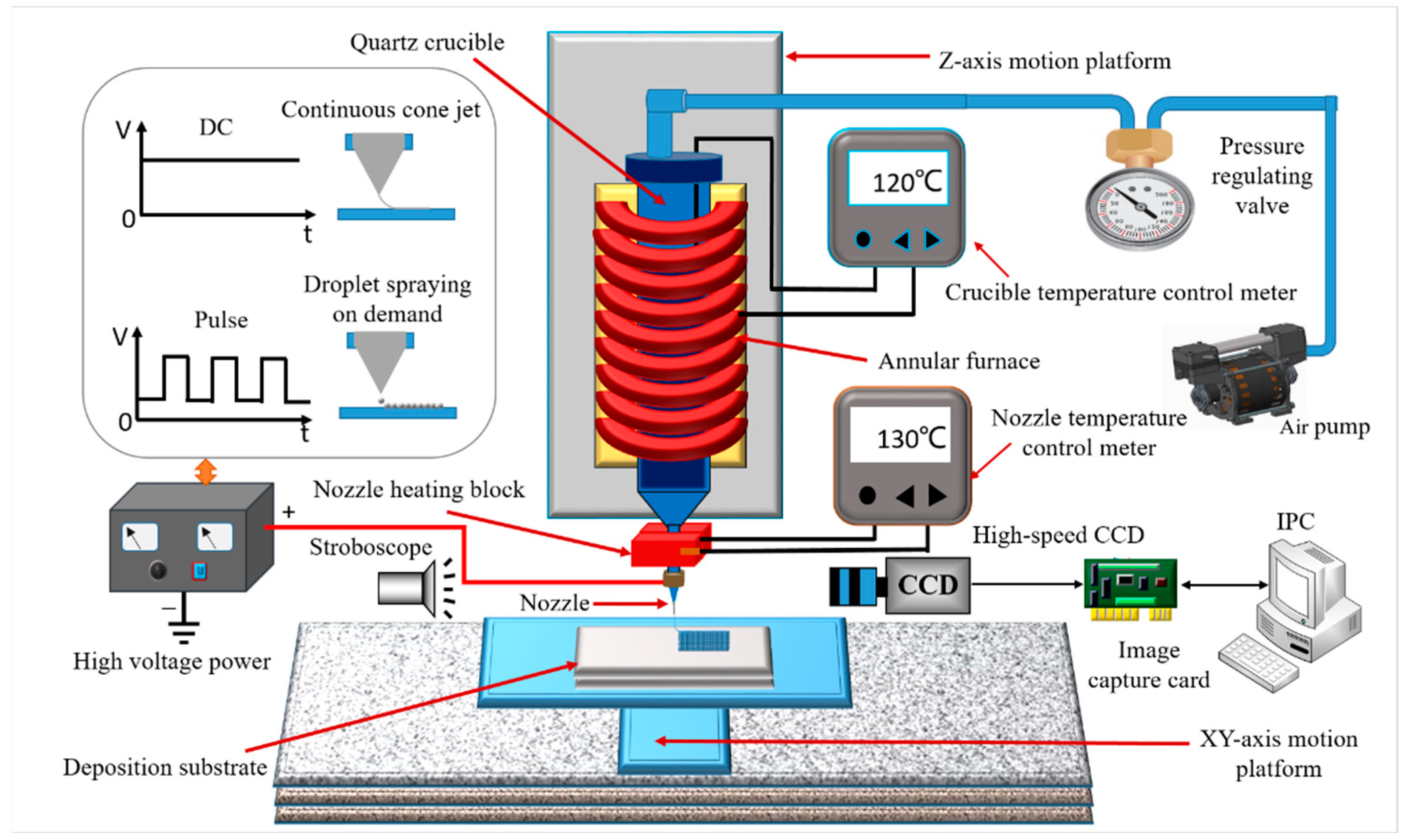
3. Experiment System

According to the above-mentioned principles, an experimental system was constructed based on an EFD continuous cone-jet deposition technology. The experimental system mainly included an air pump, a pressure-regulating valve, high-voltage power, a quartz crucible, an annular furnace, a crucible temperature control meter, a nozzle heating block, a nozzle temperature control meter, deposition substrate, an XY-axis movement platform, a Z-axis movement platform, a high speed CCD, an image capture card, a stroboscope and an industrial personal computer.
Figure 2 shows a schematic diagram of the EFD jet deposition 3D-printed experimental system. The quartz crucible is installed in the annular furnace, and the temperature of 130 °C in the crucible can be precisely controlled by the temperature controller to meet the melting conditions of the PCL material in the crucible. The printing nozzle is installed at the bottom of the quartz crucible and is connected with the positive electrode of the high voltage power supply, which can achieve 0–30,000 V DC high voltage. The nozzle heating block is installed on the outer surface of the nozzle, and the nozzle temperature can be accurately controlled at 80 °C through the temperature controller, which can meet the temperature conditions of PCL molten jet injection. The annular heating furnace is fixed on the Z-axis moving platform, which can drive the nozzle to move up and down. The deposition substrate is mounted on the XY-axis movement platform, which can realize the precise control of the motion speed and trajectory in the XY direction. The air pump is communicated with the quartz crucible through the pressure regulating valve, which is used to accurately adjust the shape of the curved liquid surface at the nozzle and control the flow of extrusion PCL material. The high-speed camera CCD is connected with the industrial computer through the data acquisition card, which can monitor the deposition change process of the Taylor cone jet in real-time. Through analysis, the calculation and feedback control, accurate deposition and printing of the molten PCL continuous cone jet can be realized. According to the printed data of the 3D model, the printing layer by layer is superimposed, and the rapid manufacturing of the whole 3D structure is finally completed.

4. Experiment Results and Discussion

4.1. Change of Extrusion Morphology of Fused PCL

In the HEF continuous cone-jet deposition printing process, in order to generate a micro-fine Taylor cone jet, it is necessary to ensure that the molten PCL material extruded from the bottom of the nozzle forms a stable menisolar surface under the action of air pressure. Polycaprolactone (PCL, CAS NO: 24980-41-4) was selected as experimental material, which is an organic polymer with the molecular formula (C6H10O2) N. By controlling the polymerization conditions, different molecular weights can be obtained. PCL is a white solid powder, non-toxic, with good biocompatibility, good organic polymer compatibility and good biodegradability. Its melting point is 65 °C, density: 1.145 g/mL at 26 °C, and after melting its liquid viscosity is 11.25 dL/Gm. Due to its high viscosity, under the action of its own gravity, the fused PCL material will not slide naturally from the nozzle to form the meniscus. Therefore, air pressure needs to be applied as back pressure. Due to the combination of gravity and air pressure, the molten, highly viscous PCL material is expelled from the bottom of the nozzle and forms a meniscus.
Figure 3 shows the extruding process of fused PCL material from the nozzle under air pressures. Figure 3a–d shows the process of the high viscosity PCL-fused material slowly ejecting from the bottom of the nozzle and finally forming the shape of the meniscus. As the air pressure continues to apply, the shape of the PCL-fused material will gradually grow. Figure 3e–h shows the high viscosity fused PCL material at the bottom of the nozzle gradually changes from the shape of the meniscus to a round sphere under the action of continuous pressure, indicating that the continuous extrusion molten PCL material needs to be deposited to maintain a dynamic equilibrium state.

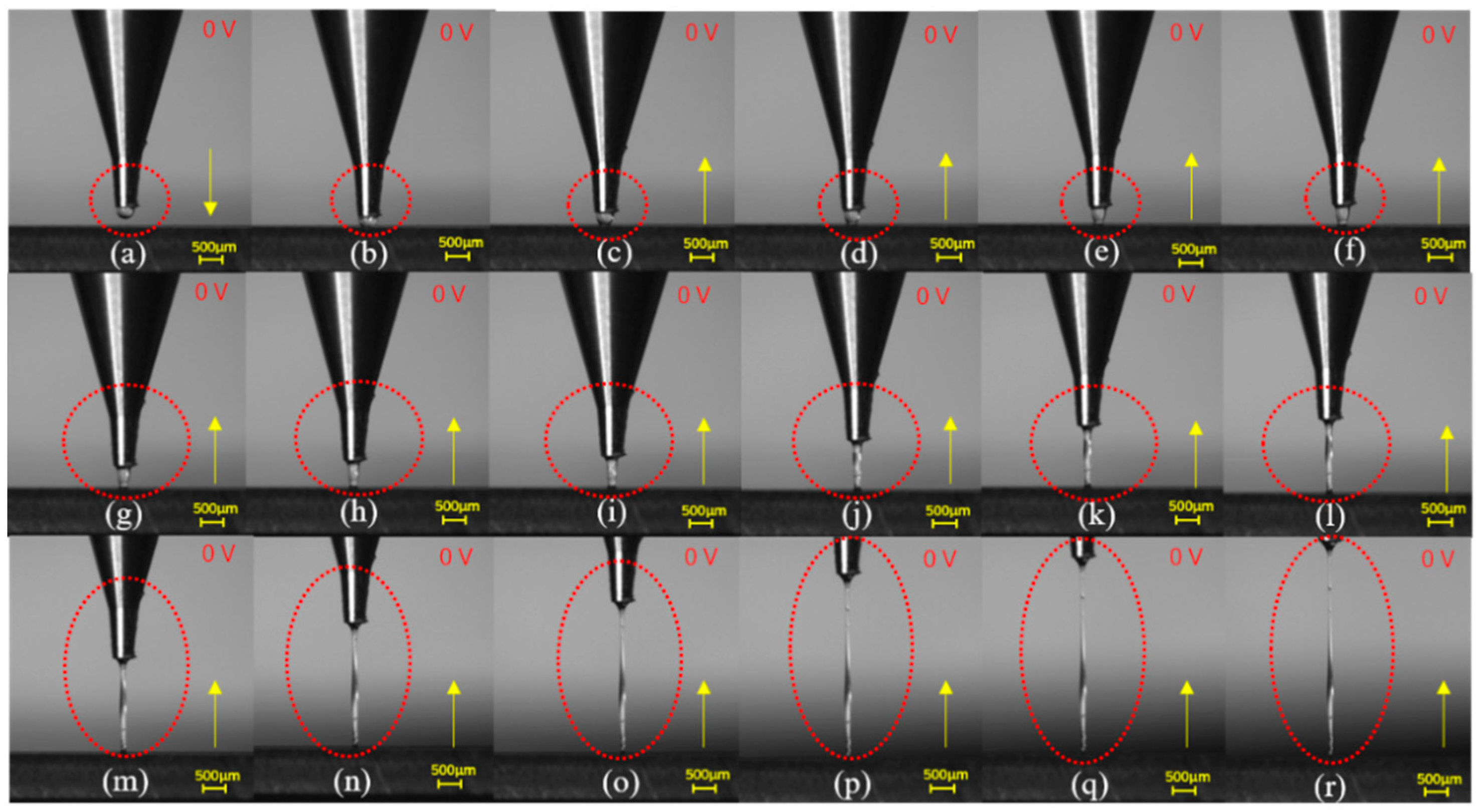
4.2. Continuous Cone Jet and Tensile Morphology

In this paper, the continuous cone-jet mode was studied. In order to reveal the influence of high-voltage electric field and viscous drag force on the morphology of the continuous cone jet, the jet drawing experiments were carried out at electric field voltages of 0 and 1600 V. Figure 4 shows that the high-viscosity PCL material was ejected from the bottom of the nozzle when the electric field voltage was 0 V. After the PCL jet was bonded to the deposited substrate, the shape of the jet was changed under the stretching of viscous drag force (FD) through the upward movement of the nozzle. Figure 4a shows the meniscus initially formed at the bottom of the nozzle, keeping the pressure continuously acting and moving the nozzle downward so that the PCL material at the bottom bonded to the surface of the deposited substrate, as shown in Figure 4b. Then, the nozzle was moved upward, and the jet started to shrink under the viscous drag force (FD) stretch, and the size became smaller. Figure 4c–i shows that the shape and size of the jet flow show obvious taper changes from the bottom of the nozzle to the deposited substrate. Continue to stretch upward, under the combined action of gravity and viscous drag force, the spindle shape appeared in the middle of the jet, as shown in Figure 4j–m. At higher stretching motions, the spindle shape in the middle of the jet remained unchanged, but the shape of the upper end of the jet was reduced more significantly, and the size became finer, and there was a tendency to fracture, as shown in Figure 4n–r.
Figure 5 shows that the high-viscosity PCL material is ejected from the bottom of the nozzle, when the electric field voltage is 1600 V. After the PCL jet was bonded to the deposited substrate, the shape of the jet was changed under the stretching of viscous drag force (FD) through the upward movement of the nozzle. Figure 5a shows the meniscus initially formed at the bottom of the nozzle, keeping the pressure continuously acting and moving the nozzle downward so that the PCL material at the bottom was bonded to the surface of the deposited substrate, as shown in Figure 5b. Then, the nozzle moved upward, and the continuously extruded jet started to change under the stretching of electric field force and viscous drag force (FD), and the size and diameter of the jet became smaller. As shown in Figure 5c–f, from the bottom of the nozzle to the deposited substrate, the jet shape and size shows a weak taper change. As the upward stretching movement continued, Figure 5g–n shows that the overall diameter size of the jet gradually decreases, but the shape and size of a single jet is very uniform, without any taper change or spindle shape. At higher stretching motions, the overall diameter of the jet becomes smaller, and obvious diameter reduction occurs at the upper end of the jet near the nozzle, as shown in Figure 5o–r. Compared to the experimental results in Figure 4, it shows that after applying a high-voltage electric field, under the action of electric field force, the jet diameter can be guaranteed to be uniform and stable within a certain deposition height range that meets the printing accuracy requirements.
Figure 6 shows the formation of the Taylor cone jet and the horizontal deposition process of PCL material under continuous jet mode. Under the action of air pressure, the PCL-fused material was extruded from nozzle to form a meniscus. When the printing nozzle was close to the deposition substrate, the liquid at the tip of Taylor cone was sprayed under the action of electric field force, and a continuous cone jet was generated, as shown in Figure 6a. When the continuous jet was deposited on the Polyethylene terephthalate (PET) substrate, with the rapid movement of the nozzle, a viscous dragging force (FD) was generated on the printing material, which further stretches the jet to form fine filaments, as shown in Figure 6b–f.

4.3. Morphology of Jet at Different Deposition Heights

The deposition height (H) is the distance between the nozzle and the deposition substrate, which mainly affects the stability of the cone jet. Under a fixed voltage, when the H is too low, the discharge between the nozzle and the conductive substrate is easy to occur, the jet is prone to whipping, the deposited line is easy to bend, and the stable jet state is difficult to control. When H is too large, the electric field between the nozzle and the substrate becomes weak and the electric field force is small, and the viscous drag force in the jet is greater than the electric field force. The bending and sloshing of jet appeared on the deposition substrate, along with the accumulation phenomenon, which makes the width of the deposition line uneven. Only when H is suitable, the cone jet can achieve stable ejection, and the straightness and size uniformity of the deposition line can be guaranteed. Figure 7 shows the deposition experimental results of the continuous cone jet at different deposition heights. The initial value of H was set as 495.45 μm, as shown in Figure 7a. The deposition height was kept unchanged and the printing nozzle moved at a uniform speed in the horizontal direction. Figure 7b–e shows the process of forming fine fibers by the cone-jet stretching. Then, to keep the deposition substrate stationary, the nozzle begins to move upward at a uniform speed, as shown in Figure 7f–o. When the deposition height is 1.108 mm, stable jet deposition can be achieved by the cone jet, as shown in Figure 7i.
As the deposition height gradually increased from 1.337 mm to 2.549 mm, it could be seen that the jet showed obvious bending, shaking and accumulating phenomena at the base deposition point, and the shape of the deposition line changed greatly. The experimental results show that when the applied voltage is 1600 V, the stable printing of the jet can be achieved in the deposition height of 495~1108 μm. Further analysis shows that there is a matching relationship between deposition height and voltage. When the applied voltage is constant, there is an effective range of deposition height to realize stable jet printing.
In order to further verify the matching relationship between deposition height and electric field voltage, the electric field voltage was increased to 1800 V. Figure 8 shows the photos of cone jet deposition of PCL materials at different deposition heights. The experimental results show that when H is 202.70 μm, 432.43 μm, 648.64 μm, 1162.16 μm and 1959.45 μm, the cone jet can achieve stable jet and deposition. There is no bending, sloshing and accumulating phenomenon at the base deposition point, and the deposition lines have good straightness and uniform size.

4.4. Width of Deposition Lines

The velocity of deposition substrate is one of the important factors affecting the line width of printed graphics, which determines the deposition amount of material per unit time on substrate. The matching degree between velocity and ejection velocity affects the slant state of the jet flow, and then affects the line width of printing. The deposition state of the jet at different velocities is shown in Figure 9. When the moving velocity of F20 is low, the jet flow is approximately perpendicular to the deposition substrate. As the moving velocity gradually is increased to F50, the jet presents an obvious backward tilt state. When the moving velocity is set as F200, much larger than the jet velocity, the jet tilt is more obvious and the jet appears to be parallel to the deposition substrate.
The experimental process parameters are shown in Table 1. The movement speeds of the deposition platform vs. were set as F10, F20, F30, F40, F50, F60, F70 and F100, respectively, in the experiment. Figure 10a shows the variation of deposition eight lines under different moving speed.
For further analysis, four position points were selected for each deposition line as observation points for line width measurement, as shown in Figure 10b,c. The line width data of each deposition line were obtained by measurement and analysis, as shown in Table 2. The measurement results show that, with increasing Vs, the width of deposition lines also gradually decreased. The width of single deposition line was basically the same. The average widths of deposition lines at different movement velocities were 55.15 μm, 36.43 μm, 25.98 μm, 21.99μm, 16.45 μm, 12.03 μm, 7.96 μm and 7.57 μm, respectively. The relationship between the width of the deposition line and the velocity of the deposition platform is approximately a quadratic curve, which was shown in Figure 11.
The analysis of the experimental results shows that the line width of the deposition line is related to the viscous drag force and the velocity of floor motion. After the PCL material is deposited on the substrate, due to the adhesion between the material and the substrate, a viscous dragging force (FD) will be generated on the deposition jet, and the FD will stretch the jet and make the jet evenly thin. Because the toughness of the PCL material is good, it will not be stretched and broken due to the increase of printing speed within a certain range.
When the movement velocities F10 is too low, on the one hand, the jet injection velocity is much higher than the deposition velocity, and the jet cannot flow back and accumulate deposition, resulting in a slight forward tilt of the jet. On the other hand, due to the small viscous drag force generated, its influence on the line width is insignificant, which eventually leads to the bending of the deposition line and the line width is thick. When the velocity of the deposition substrate gradually increases to be consistent with or greater than the jet velocity, the phenomenon of jet accumulation disappears, and the jet is vertical or backward inclined. Under the action of viscous dragging force, the deposition jet is stretched and tapered, leading to the tapering of the lines deposited on the substrate. Within a certain range, the higher the moving velocities, the finer the lines. However, when the velocity of the deposition substrate is too high, the breakage of deposition lines will occur. In this case, the pressure and voltage need to be readjusted to ensure the continuous formation of the jet to match the higher printing speed.

4.5. Straightness of Deposition Lines

The velocity of deposition substrate is one of the important factors affecting the straightness of the deposition line. The experimental process parameters are listed in Table 3, the vs. were set as F50, F100, F200, F250, F500, and F700, respectively, in the experiment. Figure 12 shows the morphology of deposition lines taken by optical microscope. The results show that the bending of the deposition line decreases gradually with the increase of the velocity. When the movement speed is F500 and F700, the straightness of deposition lines is very good. The reasons are as follows: on the one hand, the deposition height (H) is increased, the whipping effect of the jet is avoided, and the jet can achieve stable jet. On the other hand, as the velocity of deposition substrate increases, the jet deposition velocity matches the jet ejection velocity, and the jet accumulation phenomenon disappears. Under the action of the viscous drag force, the deposited jet was stretched and straightened, and the straightness of deposition lines and size uniformity was effectively improved, as shown in Figure 12e,f.

4.6. Deposition Single Layer Linear Grid

In order to further verify the feasibility of micro/nano 3D printing based on high-voltage electric field-driven jet deposition, on the basis of the above experimental research and analysis, the single layer linear grid was fabricated. The PLC was selected as printing material, and the PET film was used as a deposition substrate. The inner diameter of nozzle D was 300 μm, the air pressure in the crucible was set as 15 KPa, the temperature of the crucible Tc was set at 130 °C, and the temperature of the nozzle Tn was set at 80 °C, the motion speed of the deposition substrate was set to F700, and the applied voltage U was set to 1800 V.
Figure 13 shows the deposited results of single layer linear grid structure. The middle part and right-angle area were respectively selected for local amplification in Figure 12a. Figure 13b is an enlarged view of the middle area. It can be seen that the deposited PCL lines have a compact structure, uniform size and good straightness. Figure 13c is an enlarged view of the selected right-angle area. It can be seen that the deposited PCL lines did not deposit according to the set right angle path, but showed certain inclinations and arcs. The main reason is that the fused PCL material has certain viscoelastic properties, and there is a certain lag in the deposition process. The lag effect is obviously caused by the short printing distance of the adjacent lines at the end of the path. Five position points were selected for deposition line as observation points for line width measurement, as shown in Figure 13d. The line width measurement results of the five positions is: L1 = 10.25 μm, L2 = 10.35 μm, L3 = 10.67 μm, L4 = 10.73 μm, and L5 = 10.73 μm. The measurement results show that: the line width the deposition lines are consistent in size, the straightness of deposition lines is very good. The experimental results of deposition lines verify the feasibility of EFD continuous jet deposition PCL, which lays a technical foundation for the subsequent development of porous scaffold structure, micro lens array mold and cell culture template.

5. Conclusions

(1)
A novel PCL high-resolution fused deposition 3D Printing based on electric field-driven (EFD) jet deposition is proposed to manufacture PCL porous scaffold structures. The process principle of the continuous cone-jet printing mode was analyzed and an experimental system was constructed based on an EFD continuous cone-jet.
(2)
EFD continuous cone-jet mode was studied, a Taylor cone-jet was generated under the action of the Fs, FV, FN, FT and FP. The Taylor cone-jet was further stretched by the viscous dragging force (FD), the diameter of the jet is usually less than one-tenth of the nozzle diameter.
(3)
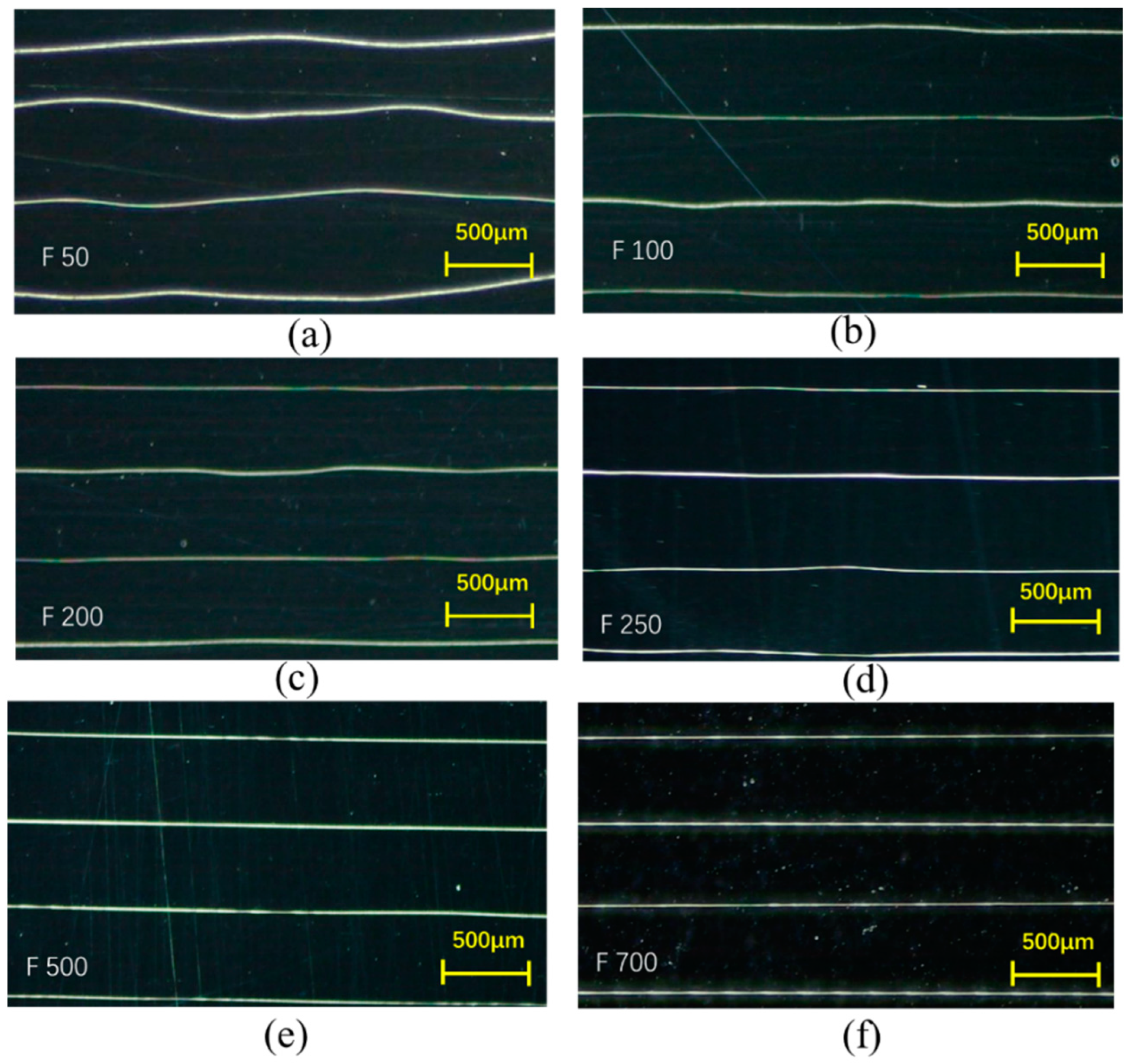
There is an effective range of deposition height (H) to realize stable jet printing. Under the stretching of electric field force and viscous drag force (FD), with the increasing of the movement velocities (Vs) the width of deposition lines was gradually decreased. The width of the deposition line and the velocity of the deposition platform is approximately a quadratic curve. The bending phenomenon of deposition lines also gradually decreases with the increase of the movement velocities.
(4)
A single layer linear grid structure was printed under the appropriate process parameters with a compact structure, uniform size and good straightness. The experimental results verify that the PCL porous scaffold structure can be accurately printed and manufactured.

Author Contributions

Y.C. conceived the idea and wrote the paper, H.Y. developed the theory and provided corrections. F.C. and S.L. performed the experiments and parameter optimization, L.M. analyzed the results and assisted with the editing of the paper. All authors have read and agreed to the published version of the manuscript.

Funding

This work was financially supported by the National Natural Science Foundation of China (grant nos. 51305128 and 52005059), Open Research Fund of State Key Laboratory of High Performance Complex Manufacturing, and Central South University (Kfkt2020-10), and Outstanding Young Backbone Teachers projects of Xu chang University.

Data Availability Statement

All the supplementary data to this article reported here can be made available on request by email.

Conflicts of Interest

The authors declare no conflict of interest.

References

  1. Bodnariuk, M.; Melentiev, R. Bibliometric analysis of micro-nano manufacturing technologies. Nanotechnol. Precis. Eng. 2019, 2, 61–70. [Google Scholar] [CrossRef]
  2. Kuo, C.L.; Yeh, T.H.; Nien, Y.P.; Chen, Y. Multi-objective optimization of edge quality and surface integrity when wire electrical discharge machining of polycrystalline diamonds in cutting tool manufacture. J. Manuf. Process. 2022, 74, 520–534. [Google Scholar] [CrossRef]
  3. Sigita, G.; Aukse, N.; Edvinas, S.; Mangirdas, M.; Angels, S.; Jolita, O. Vegetable Oil-Based Thiol-Ene/Thiol-Epoxy Resins for Laser Direct Writing 3D Micro-/Nano-Lithography. Polymers 2021, 13, 872. [Google Scholar]
  4. Hamid, H.M.A.; Celik-Butler, Z. A novel MEMS triboelectric energy harvester and sensor with a high vibrational operating frequency and wide bandwidth fabricated using UV-LIGA technique. Sens. Actuators A Phys. 2020, 313, 112175. [Google Scholar] [CrossRef]
  5. Xu, J.; Su, Q.; Shan, D.B.; Guo, B. Sustainable micro-manufacturing of superhydrophobic surface on ultrafine-grained pure aluminum substrate combining micro-embossing and surface modification. J. Clean. Prod. 2019, 232, 705–712. [Google Scholar] [CrossRef]
  6. Huang, Z.Y.; Shao, G.G.; Li, L.Q. Micro/nano functional devices fabricated by additive manufacturing. Prog. Mater. Sci. 2022, 131, 101020. [Google Scholar] [CrossRef]
  7. Liu, P.P.; Guo, Y.W.; Chen, J.Y.; Yang, Y.B. A Low-Cost Electrochemical Metal 3D Printer Based on a Microfluidic System for Printing Mesoscale Objects. Crystals 2020, 10, 257. [Google Scholar] [CrossRef] [Green Version]
  8. Pearre, B.W.; Michas, C.; Tsang, J.-M.; Gardner, T.J.; Otchy, T.M. Fast micron-scale 3D printing with a resonant-scanning two-photon microscope. Addit. Manuf. 2019, 30, 100887. [Google Scholar] [CrossRef]
  9. Farjam, N.; Cho, T.H.; Dasgupta, N.P.; Barton, K. Subtractive patterning: High-resolution electrohydrodynamic jet printing with solvents. Appl. Phys. Lett. 2020, 117, 133702. [Google Scholar] [CrossRef]
  10. Liang, P.; Shang, L.D.; Wang, Y.T.; Booth, M.J.; Li, B. Laser induced forward transfer isolating complex-shaped cell by beam shaping. Biomed. Opt. Express. 2021, 12, 7024–7032. [Google Scholar] [CrossRef]
  11. Wang, M.; Peng, Z.Y.; Huang, D.; Ning, Z.Q.; Chen, J.L.; Li, W.; Chen, J. Improving loading amount of nanodendrite array photo-electrodes on quantum dot sensitized solar cells by second electrochemical deposition. Mater. Sci. Semicond. Process. 2022, 137, 106219. [Google Scholar] [CrossRef]
  12. Wilkinson, N.J.; Kay, R.W.; Harris, R.A. Electrohydrodynamic and aerosol jet printing for the copatterning of polydimethylsiloxane and graphene platelet inks. Adv. Mater. Technol. 2020, 5, 2000148. [Google Scholar] [CrossRef]
  13. Ge, Q.; Li, Z.; Wang, Z.; Kowsari, K.; Zhang, W.; He, X. Projection micro stereolithography based 3D printing and its applications. Int. J. Extrem. Manufac. 2020, 2, 022004. [Google Scholar] [CrossRef]
  14. Kumar Singh, A.; Choudhary, A.K. On the electrical characterization of focused ion/electron beam fabricated platinum and tungsten nano wires. Mater. Today Proc. 2020, 28, 127–130. [Google Scholar] [CrossRef]
  15. Lee, Y.W.; Ceylan, H.; Yasa, I.C.; Kilic, U.; Sitti, M. 3D-printed multi-stimuli-responsive mobile micromachines. ACS Appl. Mater. Interfaces 2021, 13, 12759–12766. [Google Scholar] [CrossRef]
  16. Lee, K.H.; Lee, S.S.; Ahn, D.B.; Lee, J.; Byun, D.; Lee, S.Y. Ultrahigh areal number density solid-state on-chip microsupercapacitors via electrohydrodynamic jet printing. Sci. Adv. 2020, 6, 1692. [Google Scholar] [CrossRef] [Green Version]
  17. Udofia, E.N.; Zhou, W. 3D printed optics with a soft and stretchable optical material. Addit. Manu. 2020, 31, 100912. [Google Scholar]
  18. Ding, A.; Lee, S.J.; Ayyagari, S.; Tang, R.; Cong, T.H.; Alsberg, E. 4D biofabrication via instantly generated graded hydrogel scaffolds. Bioact. Mater. 2022, 7, 324–332. [Google Scholar] [CrossRef]
  19. Soundarya, S.P.; Menon, A.H.; Chandran, S.V. Bone tissue engineering: Scaffold preparation using chitosan and other biomaterials with different design and fabrication techniques. Int. J. Biol. Macromol. 2018, 119, 1228–1239. [Google Scholar] [CrossRef]
  20. He, J.; Xia, P.; Li, D. Development of melt electrohydrodynamic 3D printing for Coplex microscale poly (s-caprolactone) scaffolds. Biofabrication 2016, 8, 035008. [Google Scholar] [CrossRef]
  21. Qu, X.; Xia, P.; He, J.; Li, D. Microscale electrohydrodynamic printing of biomimetic PCL/nHA composite scaffolds for bone tissue engineering. Mater. Lett. 2016, 185, 554–557. [Google Scholar] [CrossRef]
  22. Ovsianikov, A.; Khademhosseini, A.; Mironov, V. The Synergy of Scaffold-Based andScaffold-Free Tissue Engineering Strategies. Trends Biotechnol. 2018, 36, 348–357. [Google Scholar] [CrossRef] [PubMed]
  23. Hong, X.Y.; Xiao, G.Q.; Zhang, Y.Z.; Zhou, J. Research on gradient additive remanufacturing of ultra-large hot forging die based on automatic wire arc additive manufacturing technology. Int. J. Adv. Manuf. Technol. 2021, 116, 2243–2254. [Google Scholar] [CrossRef]
  24. Dou, Y.B.; Luo, J.; Qi, L.H.; Lian, H.C.; Huang, J.G. Drop-on-demand printing of recyclable circuits by partially embedding molten metal droplets in plastic substrates. J. Mater. Process. Tech. 2021, 297, 117268. [Google Scholar] [CrossRef]
  25. Wohlers Report 2022, Analysis, Trends, Forecasts, 3D Printing and Additive Manufacturing State of the Industry. Available online: https://wohlersassociates.com/product/wohlers-report-2022/ (accessed on 20 October 2022).
  26. Kollamaram, G.; Croker, D.M.; Walker, G.M.; Goyanes, A.; Basit, A.W.; Gaisford, S. Low temperature fused deposition modeling (FDM) 3D printing of thermolabile drugs. Int. J. Pharm. 2018, 545, 144–152. [Google Scholar] [CrossRef] [Green Version]
  27. Corcione, C.E.; Gervaso, F.; Scalera, F.; Padmanabhan, S.K.; Madaghiele, M.; Montagna, F.; Sannion, A.; Licciulli, A.; Maffezzoli, A. Highly loaded hydroxyapatite microsphere/PLA porous scaffolds obtained by fused deposition modelling. Ceram. Int. 2019, 452, 2803–2810. [Google Scholar] [CrossRef]
  28. Zuo, M.; Pan, N.; Liu, Q.; Ren, X.H.; Liu, Y.; Huang, T.S. Three-dimensionally printed polylactic acid/cellulose acetate scaffolds with antimicrobial effect. RSC Adv. 2020, 10, 2952–2958. [Google Scholar] [CrossRef] [Green Version]
  29. Zhou, L.; Ramezani, I.H.; Sun, M. 3D printing of high-strength chitosan hydrogel scaffolds without any organic solvents. Biomater. Sci. 2020, 8, 5020–5028. [Google Scholar] [CrossRef]
  30. Giustina, G.D.; Gandin, A.; Brigo, L.; Panciera, T.; Giulitti, S.; Sgarbossa, P.; D’Alessandro, D.; Trombi, L.; Danti, S.; Brusatin, G. Polysaccharide hydrogels for multiscale 3D printing of pullulan scaffolds. Mater. Des. 2019, 165, 107566. [Google Scholar] [CrossRef]
  31. Meng, Z.; He, J.; Cai, Z.; Wang, F.; Zhang, J.; Wang, L.; Di, R.; Li., C. Design and additive manufacturing of flexible polycaprolactone scaffolds with highly-tunable mechanical properties for soft tissue engineering. Mater. Des. 2020, 189, 108508. [Google Scholar] [CrossRef]
  32. Kaifur, R.; Abdullah, K.; Ranya, S.; Stuart, B. Fused filament fabrication of nylon 6/66 copolymer: Parametric study comparing full factorial and Taguchi design of experiments. Rapid Prototyp. J. 2022, 28, 1111–1128. [Google Scholar]
  33. Chanun, S.; Anchalee, M. On the build orientation effect in as-printed and as-sintered bending properties of 17-4PH alloy fabricated by metal fused filament fabrication. Rapid Prototyp. J. 2022, 28, 1076–1085. [Google Scholar]
  34. Chitralekha, N.; Kumar, G.P. Transient thermal finite-element analysis of fused filament fabrication process. Rapid Prototyp. J. 2022, 28, 1097–1110. [Google Scholar]
  35. He, Y.; Yang, F.; Zhao, H.; Gao, Q.; Xia, B.; Fu, Z.J. Research on the printability of hydrogels in 3D bioprinting. Sci. Rep. 2016, 6, 29977. [Google Scholar] [CrossRef] [PubMed] [Green Version]
  36. Lu, F.; Wu, R.; Shen, M.; Xie, L.; Gou, Z. Rational design of bioceramic scaffolds with tuning pore geometry bystereolithography: Microstructure evaluation and mechanical evolution. J. Eur. Ceram. Soc. 2021, 41, 1672–1682. [Google Scholar] [CrossRef]
  37. Kolan, K.C.; Li, J.; Roberts, S.; Semon, J.A.; Park, J.; Day, D.E.; Ming, C.L. Near-field electrospinning of a polymer/bioactive glass composite to fabricate 3D biomimetic structures. Int. J. Bioprinting 2019, 5, 163. [Google Scholar] [CrossRef]
  38. Park, Y.S.; Kim, J.; Oh, J.M.; Park, S.Y.; Cho, S.; Ko, H.; Cho, Y.K. Near-field electrospinning for three-dimensional stacked nanoarchitectures with high aspect ratios. Nano Lett. 2019, 20, 441–448. [Google Scholar] [CrossRef]
  39. Robinson, T.M.; Hutmacher, D.W.; Dalton, P.D. The next frontier in melt electrospinning: Taming the jet. Adv. Funct. Mater. 2019, 29, 1904664. [Google Scholar] [CrossRef] [Green Version]
  40. Ding, H.; Cao, K.; Zhang, F.; Bettcher, W.; Chang, R.C. A fundamental study of charge effects on melt electrowritten polymer fibers. Mater. Des. 2019, 178, 107857. [Google Scholar] [CrossRef]
  41. Brown, T.D.; Dalto, P.D.; Hutmacher, D.W. Direct writing by way of melt electrospinning. Adv. Mater. 2011, 23, 5651–5657. [Google Scholar] [CrossRef]
  42. He, F.L.; Li, D.W.; He, J.; Liu, Y.Y.; Ahmad, F.; Liu, Y.L.; Deng, X.; Ye, Y.J.; Yin, D.C. A novel layer-structured scaffold with large pore sizes suitable for 3D cell culture prepared by near-field electrospinning. Mater. Sci. Eng. C 2018, 86, 18–27. [Google Scholar] [CrossRef] [PubMed]
  43. Eichholz, K.F.; Hoey, D.A. Mediating human stem cell behaviour via defined fibrous architectures by melt electrospinning writing. Acta Biomater. 2018, 75, 140–151. [Google Scholar] [CrossRef] [PubMed]
  44. Hrynevich, A.; Elçi, B.Ş.; Haigh, J.N. Dimension based design of melt electrowritten scaffolds. Small 2018, 14, 1800232. [Google Scholar] [CrossRef] [PubMed]
  45. Kan, Y.Y.; Bondareva, J.V.; Statnik, E.S.; Cvjetinovic, J.; Lipovskikh, S.; Abdurashitov, A.S.; Kirsanova, M.A.; Sukhorukhov, G.B.; Evlashin, A.A.; Salimon, A.I.; et al. Effect of Graphene Oxide and Nanosilica Modifications on Electrospun Core-Shell PVA–PEG–SiO2PVA–GO Fiber Mats. Nanomaterials 2022, 12, 998. [Google Scholar] [CrossRef] [PubMed]
  46. Tourlomousis, F.; Ding, H.; Kalyon, D.M.; Chang, R.C. Melt electrospinning writing process guided by a “Printability Number”. J. Manuf. Sci. Eng. 2017, 139, 081004. [Google Scholar] [CrossRef]
  47. Chao, Y.P.; Yi, H.; Cao, F.L.; Li, Y.H.; Cen, H.; Lu, S. Experimental Analysis of Wax Micro-Droplet 3D Printing Based on a High-Voltage Electric Field-Driven Jet Deposition Technology. Crystals 2022, 12, 277. [Google Scholar] [CrossRef]
  48. Zhang, G.; Lan, H.; Qian, L.; Zhao, J.; Wang, F. A microscale 3D printing based on the electric-field-driven jet. 3D Print. Add. Manufact. 2020, 7, 37–44. [Google Scholar] [CrossRef]
  49. Wang, Z.; Zhang, G.M.; Huang, H.; Qian, L.; Liu, X.L.; Lan, H.B. The self-induced electric-field-driven jet printing for fabricating ultrafine silver grid transparent electrode. Virtual Phys. Prototyp. 2021, 16, 113–123. [Google Scholar] [CrossRef]
Figure 1. Schematic diagram of a continuous cone-jet deposition based on high-voltage electric field.
Crystals 12 01660 g001
Figure 2. Schematic diagram of EFD jet deposition 3D printing experimental system.
Crystals 12 01660 g002
Figure 3. Extruding process of the fused PCL material under air pressures. (ad) the forming process the shape of the meniscus; (eh) the process of changing from the shape of the meniscus to a round sphere.
Crystals 12 01660 g003
Figure 4. Vertical tensile morphology of jet at 0 V DC voltage. (a) the meniscus initially formed at the bottom of the nozzle; (b) the PCL material at the bottom was bonded to the surface of the deposited substrate; (ci) the shape and size of the jet flow show obvious taper changes; (jm) the spindle shape appeared in the middle of the jet; (nr) the jet size became finer, and there was a tendency to fracture.
Crystals 12 01660 g004
Figure 5. Vertical tensile morphology of jet at 1600 V DC voltage. (a) the meniscus initially formed at the bottom of the nozzle; (b) the PCL material at the bottom was bonded to the surface of the deposited substrate; (cf) the nozzle moved upward, the jet shape and size shows a weak taper change; (gn) the overall diameter size of the jet gradually decreases; (or) the obvious diameter reduction occurs at the upper end of the jet near the nozzle.
Crystals 12 01660 g005
Figure 6. Continuous conical jet formation and horizontal deposition morphology. (a) a continuous cone jet was generated, (bf) the process of cone jet is further stretched to form fine filaments under viscous dragging force (FD).
Crystals 12 01660 g006
Figure 7. Deposition morphology of jet at different deposition heights. (a) The initial value of H was set as 495.45 μm; (be) the process of forming fine fibers by the cone-jet stretching; (fo) the nozzle begins to move upward at a uniform speed.
Crystals 12 01660 g007
Figure 8. Stable deposition of continuous cone jet at an effective deposition height. (a) H is 202.70 μm; (b) H is 432.43 μm; (c) H is 648.64 μm; (d) H is 1162.16 μm; (e) H is 1959.45 μm.
Crystals 12 01660 g008
Figure 9. Deposition morphology of jet under different substrate velocities.
Crystals 12 01660 g009
Figure 10. Variation of deposition line width under different moving speeds. (a) the variation of deposition eight lines under different moving speed; (b) four position points were selected for each deposition line; (c) the line width measured data of each deposition line.
Crystals 12 01660 g010
Figure 11. Conic relationship between line width and the velocity of deposition platform.
Crystals 12 01660 g011
Figure 12. Variation of straightness of the deposition line under different velocities. (a) F50; (b) F100; (c) F200; (d) F250; (e) F500; (f) F700.
Crystals 12 01660 g012
Figure 13. Deposition Single Layer Linear Grid. (a) the deposited single layer linear grid structure; (b) an enlarged view of the middle area; (c) an enlarged view of the selected right-angle area; (d) five position points were selected for deposition line as observation points for line width measurement.
Crystals 12 01660 g013
Table 1. The process parameters of printing deposition lines.
Process Parameters
Printing MaterialDeposition
Substrate
Diameter of the Nozzle:
D (μm)
Deposition Height:
H (μm)
PCL (Polycaprolactone)PET (Polyethylene terephthalate)300200
Electric field voltage: U (v)Temperature of the crucible: Tc (°C)Temperature of the nozzle: Tn (°C)Air pressure: KPa
16001308015
Movement speed of the deposition platform: vs. (Plus/s)
12345678
F10F20F30F40F50F60F70F100
Table 2. The measurement data of depositing line.
Line Width (μm) Line Width (μm)
F10Average: 55.15F50Average: 16.45
1.54.523.54.681.16.683.16.26
2.55.634.55.782.16.944.15.95
F20Average: 36.43F60Average: 12.03
1.36.453.37.231.12.453.12.35
2.35.684.36.372.11.864.11.47
F30Average: 25.98F70Average: 7.96
1.26.753.26.321.7.893.8.65
2.25.864.24.992.7.964.7.36
F40Average: 21.99F100Average: 7.57
121.34321.7617.6837.66
222.52422.3527.1847.75
Table 3. The process parameters of printing deposition lines.
Process Parameters
Printing MaterialDeposition SubstrateDiameter of the Nozzle: D (μm)Deposition Height: H (μm)
PCL (Polycaprolactone)PET (Polyethylene terephthalate)3001000
Electric field voltage: U (v)Temperature of the crucible: Tc (°C)Temperature of the nozzle: Tn (°C)Air pressure: KPa
18001308015
Movement velocity of the deposition platform: vs. (Plus/s)
123456
F50F100F200F250F500F700
Publisher’s Note: MDPI stays neutral with regard to jurisdictional claims in published maps and institutional affiliations.

