Article

Machining Performance Analysis of Rotary Ultrasonic-Assisted Drilling of SiCf/SiC Composites

1
National Key Laboratory of Science and Technology on Helicopter Transmission, Nanjing University of Aeronautics and Astronautics, Nanjing 210016, China
2
JITRI Institute of Precision Manufacturing, Nanjing 211806, China
*
Authors to whom correspondence should be addressed.
Crystals 2022, 12(11), 1658; https://doi.org/10.3390/cryst12111658
Submission received: 25 October 2022 / Revised: 10 November 2022 / Accepted: 11 November 2022 / Published: 17 November 2022
(This article belongs to the Special Issue Processing Technology of Brittle Crystal Materials)

Abstract

:
An SiCf/SiC composite has the following excellent properties: high strength, low specific gravity, and high temperature resistance, which has great prospects in the combustion chamber of rockets or aero engines. Hole-making in SiCf/SiC parts is an important processing method. Generally, water-based or oil-based coolants are avoided, so dry drilling is the primary hole-making approach for SiCf/SiC. However, the abrasion resistance and high hardness of SiCf/SiC often lead to fast tool wear as well as serious damage to the fiber and matrix during dry drilling. This study proposes an innovative strategy for hole-making in SiCf/SiC parts—rotary ultrasonic-assisted drilling (RUAD) using an orderly arranged brazed diamond core drill. The influence of tool life and wear on drilling accuracy is analyzed. Additionally, the impacts of the process parameters of conventional drilling (CD) and RUAD on drilling force, torque, the surface roughness of the hole wall, and the exit tearing factor are investigated. The results show that the orderly arranged brazed diamond core drill exhibits longer tool life and higher accuracy in hole-making. Meanwhile, compared with CD, RUAD with the proposed core drill effectively improves the drilling quality and efficiency, and reduces the force and torque of drilling. The range of process parameters for dry drilling is broadened.

1. Introduction

Silicon-carbide-fiber-reinforced-silicon-carbide (SiCf/SiC), one of the ceramic matrix composites, is a newly developed high-temperature-resistant lightweight material. SiCf/SiC has the following excellent properties: high temperature and wear resistance, high strength, and high hardness, and is thus a promising material for highly heat-resistant structural parts and long-life functional parts, e.g., combustor or blades in the LEAP-X1C or GE9X aero-engines [1,2,3]. These aero-engine components contain multiple holes for various purposes, such as assembling, connecting, and cooling. At the same time, SiCf/SiC is challenging to drill [4]. First, the tools wear prematurely, so the normal drilling operation is hard to maintain. Second, conventional drilling (CD) of SiCf/SiC results in high roughness of hole walls and severe tearing of hole exits because of the large drilling force. Third, SiCf/SiC composites must be dry-drilled because conventional coolants may adversely affect the fiber/matrix interface. Therefore, it is essential to research suitable tools and strategies for drilling SiCf/SiC composites.
Similar to other ceramic matrix composites (CMCs), SiCf/SiC parts are prepared by near-net-shape processes [5]. However, most parts still need precision machining to meet the requirements for precision and surface quality [6]. Hole-making on the SiCf/SiC parts occupies a large proportion [3]. Conventional drilling causes severe tool wear and has poor quality, low efficiency, and high cost [7]. Non-conventional drilling methods mainly include the following: laser drilling [8], abrasive waterjet drilling [9], electric discharge drilling (EDD) [10], and ultrasonic vibration-assisted drilling [11,12]; each method has its advantages and disadvantages. Laser drilling is non-contact, eliminating issues such as defects and frequent tool changes caused by tool wear during machining [13]. However, the disadvantages of laser drilling include low efficiency and difficulties in maintaining high accuracy, particularly when making holes with relatively large depths or diameters [14]. In addition, laser processing creates a heat-affected zone within the irradiated area. It may worsen the material’s mechanical properties in that zone, thus deteriorating the lifetime and performance of the part [15]. Abrasive waterjet drilling has fast processing speed and high efficiency, whereas its disadvantages are poor surface quality, low accuracy, and severe edge tearing in hole-making [16]. EDD can machine various shapes through diverse electrode shapes and perform deep cutting; however, it also creates a heat-affected zone in the area affected by the electric arc on the surface/subsurface of a material. Moreover, ceramic matrix composites are mostly electrical insulators (or semiconductors), and the machining efficiency of EDD is very low, which limits the further development of this technology [17]. Ultrasonic-assisted drilling (UAD) reduces drilling forces, improves machined surface quality, alleviates tool wear, and extends tool life. Therefore, it has attracted considerable attention in hard and brittle material processing [18]. Hocheng et al. [19] conducted a comparative processing test on CD and UAD of C/SiC. The results showed that the tool wear was minor, and the material removal rate and drilling quality of UAD were better than those of CD. Feng et al. [20] conducted RUAD of C/SiC using a diamond core drill with various grain sizes. They found that the hole exit tearing was positively correlated with the thrust force, and RUAD could reduce hole exit tear defects by 60%. Wang et al. [21,22] performed multiple rotary ultrasonic machining (RUM) tests on 2D-C/SiC with an 8 mm diameter diamond core drill and showed that RUM could ameliorate the hole surface quality. Ding et al. [23] machined SiC ceramic using ultrasonic-assisted grinding (UAG) and concluded that UAG ultimately decreased the surface/subsurface breakage and surface roughness by reducing grinding force and energy. Therefore, UAD is a suitable machining method for the high-quality drilling of ceramic matrix composites.
However, most of the published studies on the RUM of CMC used coolants. At the same time, SiCf/SiC composites generally need to be machined under dry conditions to avoid contamination of the interior material by the coolant. Moreover, tool wear is faster during dry drilling, and hole quality is worse than the drilling with a coolant [24]. The major solution to this problem is to use diamond tools for drilling. Commonly used diamond tools are prepared by electroplating, sintering, and brazing. Electroplated diamond tools have a relatively simple preparation process that is mature and stable, and thus have a low price. However, because the abrasive grains and the electroplating layer are combined through simple mechanical embedding, the holding strength between the abrasive grains and the electroplating matrix is low, resulting in the easy fall-off of the abrasive grains and a quick loss of the processing ability during the machining of difficult-to-cut material [25]. Sintered diamond tools have high grain holding strength, but most grains are buried in the metal binding agent with a low protrusion height, so the cutting ability is relatively low [26]. Brazed diamond tools have a high grain protrusion height and high matrix-grain holding strength, capable of maintaining good machining performance under high drilling forces and temperatures [27]. In addition, the orderly arranged brazed diamond tools have adequate space for storing chips, and high tool sharpness results in excellent dry machining performance [28]. However, there is little research on improving tool life and drilling quality of SiC/SiC composites by using the orderly arranged brazed diamond core drill and RUAD with the dry drilling method.
It is still in the preliminary research stage that dry drilling of SiCf/SiC composites is carried out with orderly arranged brazed diamond tools. Studies on the machining performance of such tools for drilling SiCf/SiC composites are insufficient. Therefore, this study investigates dry rotary ultrasonic-assisted drilling (RUAD) of SiCf/SiC composites using an orderly arranged brazed diamond core drill. This study aims to provide fundamental guidance and basic process data on the efficient processing method and high-quality dry drilling of SiCf/SiC composites.

2. Materials and Methods

2.1. Workpiece

In this study, the workpiece is a 2D SiCf/SiC composite plate, and the thickness is 4 mm. The material comprises SiC fiber, BN interface layer, and SiC matrix; it also contains randomly distributed pores. The porosity inside the material is 20%. The SiC fiber’s type is T300, with a diameter of 5–7 μm. The chemical vapor infiltration (CVI) method is used for material preparation [29]. First, SiC fiber yarns are made into a fiber preform according to a 2D weaving method, as shown in Figure 1a; second, the fiber preform is put into the CVI reactor. The gaseous precursor enters the reactor according to a certain proportion and penetrates the void of the fiber preform by diffusion; a chemical reaction occurs on the surface of the SiC fiber and deposits in situ to form a BN interface layer and SiC matrix. In general, in order to reduce the CMCs machining challenges (fast tool wear and poor machining quality), the SiCf/SiC composites in machining are not final-state materials, which means the materials are not completely densified [30]. Afterward, the densification is again conducted to increase the properties of the SiCf/SiC composite, such as density, hardness, strength, etc. Additionally, after the densification, whether further machining is needed or not depends on specific quality requirements.
We observe the micromorphology on the side of the polished SiCf/SiC composite. The SiC fibers of each layer are arranged in transverse and longitudinal directions, and the fibers in different directions are woven in a plain weave pattern, as shown in Figure 1a. Pores of various sizes are distributed between plain weave layers (Figure 1b), and the presence of pores is expected to affect the drilling force during mechanical drilling. Figure 1c,d presents the micromorphology of SiC fibers in transverse and longitudinal directions, where the SiC fibers are tightly wrapped by BN interfacial layer and SiC matrix. Compared with SiC ceramics, this woven structure endows SiCf/SiC composites with higher fracture toughness and better impact resistance under extreme conditions. The mechanical properties of SiCf/SiC composites and SiC ceramics are shown in Table 1 [31,32].
Table 1. Mechanical properties of the SiC and SiCf/SiC workpiece [31,32].
MaterialDensity
(g/cm3)
Elastic Modulus
(GPa)
Hardness
(GPa)
Fracture Toughness
(MPa·m1/2)
Flexural Strength
(MPa)
SiC3.214410253500–600
SiCf/SiC2.292892026.4570

2.2. Drilling Tool

The drilling tool used in this study is an orderly arranged brazed diamond core drill developed in-house. This tool has high abrasive grain protrusion height, adequate space for drilling chips, and high holding strength between the abrasive grains and the tool matrix; it is suitable for dry-drilling CMCs. Figure 2a shows the overall appearance and the following three sections of the orderly arranged brazed diamond core drill: the working section containing diamond abrasive grains, tool neck, and holding shank. The working section’s diameter is 4 mm, and the diamond abrasive grain size is 40/45 mesh (average size in the range of 425–450 μm). The abrasive grains of the working section are orderly arranged into eight 15-grain rows with a length of 7 mm, and there are four symmetrical arc grooves with diamond abrasive grains welded on the tool end (as shown in Figure 2b,c). Hence, this structure can effectively accommodate the abrasive chips generated during dry drilling and discharge them from the drilling area. In addition, new tools are used for each set of tests to avoid the impact of tool wear on the test data in this study.

2.3. Experimental Setup

Conventional drilling and RUAD are performed on a 5-axis vertical high-speed machining center (DMG Ultrasonic 20 Linear, Germany), as shown in Figure 3a. The maximum spindle speed of machining center is 42,000 rpm, and the maximum travel of the X, Y, Z axis are 200 mm, 220 mm, and 280 mm respectively. The RUAD is performed using the HSK-E32 ultrasonic tool holder with a 20,000 rpm maximum speed and an in-house ultrasonic system. The workpiece is clamped by a pressure plate on a special fixture for drilling tests, as shown in Figure 3b. All tests are performed under dry drilling conditions, following specific machining parameters shown in Table 2. This paper first tests the drilling performance of an orderly arranged brazed diamond core drill in RUAD (n = 12,000 rpm, vw = 30 mm/min, f = 23.5 kHz, A = 5 μm), and then, the influence of drilling parameters on drilling force, torque and drilling quality are investigated by single factor test with new tools. Vacuum cleaning removes chips during drilling to avoid contaminating the environment and the machine spindle.

2.4. Measurement Method

Before ultrasonic vibration-assisted drilling, the top of the tool’s amplitude is measured by an eddy current sensor (DT3301) with a sampling frequency of 100 kHz (Figure 4a). To record the high-frequency alternating voltage signal measured by the eddy current sensor is connected by the oscilloscope as shown in Figure 4b. The relationship between ultrasonic amplitude and voltage can be calculated by Equation (1) [33].
A U = φ × U ,
where AU is the top of the tool’s ultrasonic amplitude, φ is the amplitude-to-voltage ratio (50 μm/V), and U is the output voltage. When the spindle speed n is 8000 rpm, the resonant frequency is 23.5 kHz, and the ultrasonic amplitude at the core drill tip is 5 μm.
The dynamometer (Kistler 9272 with a 5070 charge amplifier) measures the drilling forces and torques, and then these process signals are collected by a data acquisition card into a computer (Figure 4b). Dynoware, a dynamometer-specific software, saves and processes the collected data. The tearing of the hole exit after drilling is recorded by a 3D video microscope (HIROX KH-7700). The confocal microscope (Sensofar Neo S) measures the hole wall’s surface roughness Sa, and the results are obtained by measuring each hole three times.

3. Results and Discussion

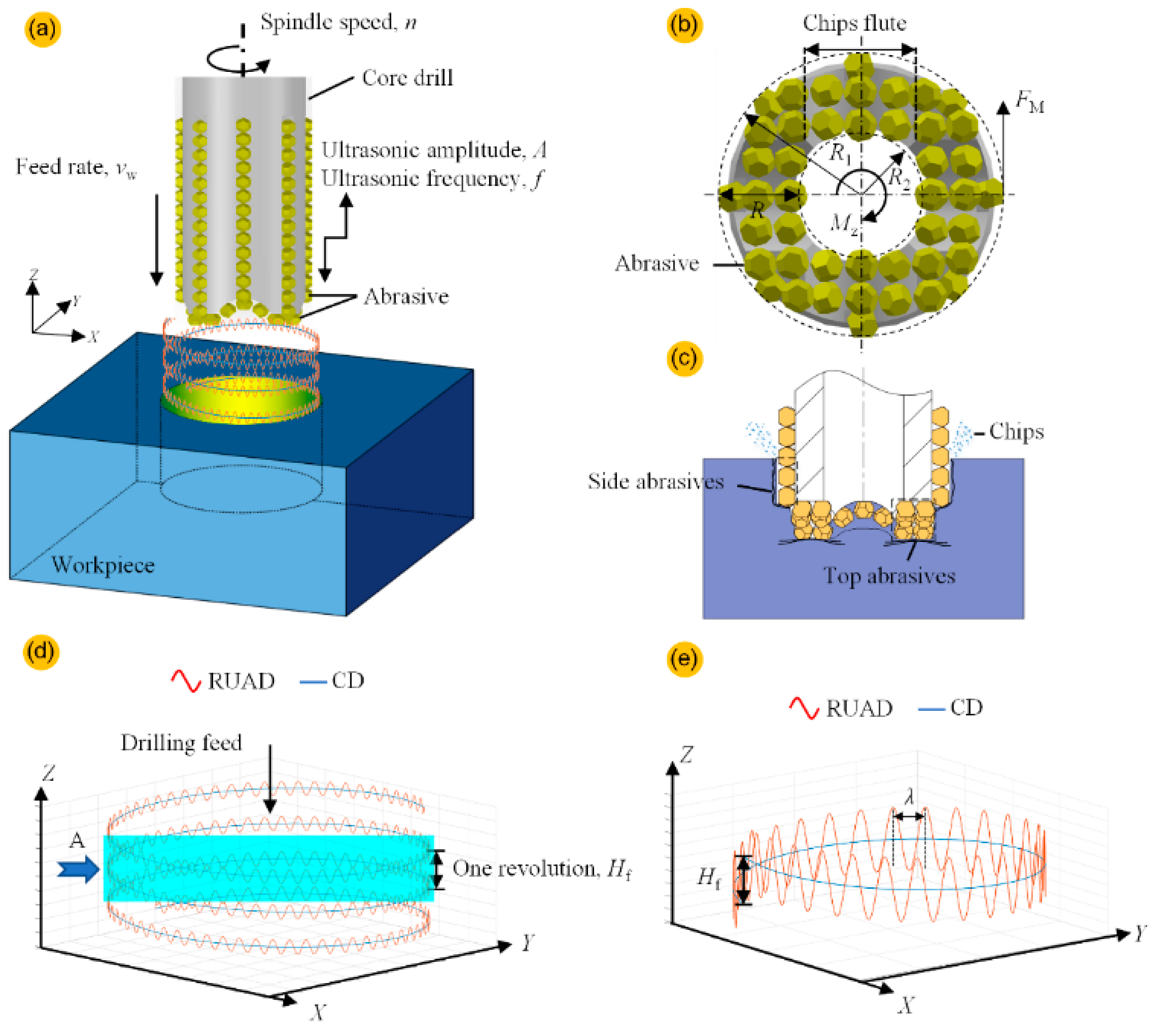
3.1. Kinematic Analysis of RUAD Process

The mechanism of RUAD and the abrasive grain motion trajectory are shown in Figure 5. The trajectory of abrasive grain motion during CD consists of rotation along the tool axis and uniform motion in the feed direction. In the RUAD, a frequency of vibration greater than 20 kHz is applied along the Z-axis in addition to CD, as shown in Figure 5a. The motion trajectories of the tool during CD and RUAD of a single diamond grain can be depicted by Equations (2) and (3) [12].
X CD t = R 1 cos 2 π n t 60 Y CD t = R 1 sin 2 π n t 60 Z CD t = v w t ,
X RUAD t = R 1 cos 2 π n t 60 Y RUAD t = R 1 sin 2 π n t 60 Z RUAD t = v w t + A sin 2 π f t ,
where R1 is the distance from the vertex of the abrasive grains on the tool to the axis, f is the frequency, A is the amplitude, t is the drilling time, vw is the feed rate, and n is the spindle speed.
According to Figure 5b,c, the diamond grains at the tooltip are the first to contact the workpiece and remove the largest volume of workpiece material during drilling. The abrasive grains in the front portion of the diamond core drill side grind the hole wall material and eventually form the hole wall morphology. Although they remove the least amount of material, the rear part of the tool’s abrasive grains significantly contributes to hole consistency and increase the useful tool life during continuous hole-making.
As shown in Figure 5d, Equations (2) and (3) visualize a single diamond grain’s trajectory. The comparison between the single diamond grain’s motion trajectory in RUAD and CD shows that the diamond grain’s motion path length under the superposition of ultrasonic vibration is longer than that during CD. This indicates a shorter depth of cut for the single abrasive grain during RUAD compared with that in CD [12]. In addition, under specific processing parameters, the abrasive grains at the top of the core drill maintain a “contact-separation” state in the SiCf/SiC composite. It can change the stress state of the impact point between the abrasive grain and material, thereby increasing the microscopic fragmentation of the abrasive grains and improving the self-sharpening ability [34].

3.2. Tool Life

While drilling SiCf/SiC composites, the tool life directly affects the machining efficiency and production cost. This study first conducts tool-life tests on orderly brazed diamond core drills. The experiments are conducted under dry RUAD using the ultrasonic machining settings specified in Table 2, a spindle speed n of 12,000 rpm, and a feed rate vw of 30 mm/min. During the test, the tool is continuously used to drill until failure.
Figure 6a indicates that the orderly arranged brazed diamond core drill makes 102 holes under dry RUAD conditions. Under the same conditions, the SiCf/SiC composite is drilled by a commercial electroplated diamond core drill (Berun Japan, Φ 4 mm and 100 mesh). The electroplated core drill can make a hole under the same dry RUAD conditions. In this case, the in-house developed, orderly arranged brazed diamond core drill has a significant advantage over a long lifetime and improves drilling efficiency.
From hole 1 to hole 92, the process is in a stable wear state, during which the hole diameter ranges from 4.01 to 4.04 mm, and the difference from the maximum to minimum diameter is 0.03 mm. From hole 93 to hole 102, the process is in a rapid wear state, and the hole diameter ranges from 3.95 to 3.99 mm, and the maximum and minimum hole diameters are 0.09 mm in the whole state. In this stage, the tool no longer meets the requirements of high precision hole making (4 ± 0.03 mm) and thus is considered to have failed. Figure 6b shows the trend in the drilling force throughout the hole-making process. Before hole 80, the drilling force is below 8 N. In this case, the top and side abrasive grains slowly wear out, the abrasive grains involved in drilling are in the stable wear stage, and the hole diameter remains within a certain range. As the tool kept making more holes, the wear of the top abrasive grains progressed, resulting in a sharp increase in drilling force (a maximum increase of 62.5%), indicating the start of the tool’s rapid wear stage. In actual manufacturing, when the tool is in the rapid wear stage, the machining should be stopped. The tool should be replaced in time to reduce the generation of scrap caused by the excessive difference in hole diameters. According to the hole diameters and variation in drilling force between hole 81 and hole 92, the tool is about to enter the rapid wear stage; the drilling force increases sharply, while the hole diameter is still maintained within the deviation of 0.03 mm. This can provide operators with more indicators to avoid scrap generation before the complete failure of the tool.
The orderly arranged brazed diamond core drill combined with the RUAD increases the number of high-quality holes produced in SiCf/SiC composites under dry conditions. The tool structure ensured stable wear of abrasive grains, and RUAD significantly reduced the axial force, thus extending the core drill life and improving the drilling quality. The following sections assessed the impact of different drilling methods and process parameters on drilling force and hole-making quality in the stable tool wear stage.

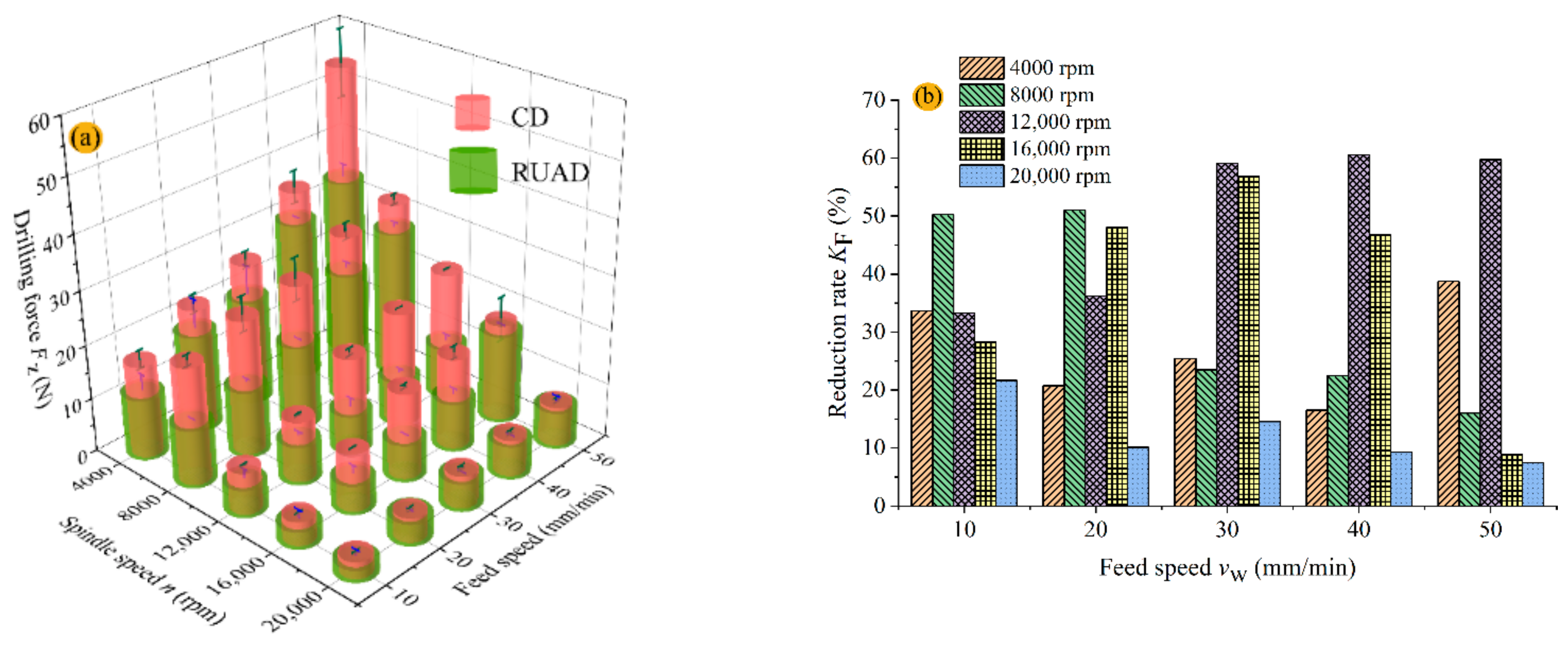
3.3. Drilling Force and Torque

The original signals of drilling force and torque obtained in the ultrasonic-assisted dry drilling of SiCf/SiC composite by the brazed diamond tool reveal that the whole drilling process has gone through the following four stages: AB, BC, CD, and DE (Figure 7). AB is the entrance drilling phase, where the diamond grains at the top of the brazed diamond tool enter the uppermost SiCf/SiC workpiece at moment A. As more abrasive grains participate in drilling, the drilling force gradually increases. BC is the stable drilling stage, in which the diamond grains at the top and the front side of the core drill are involved in processing; the axial force at this stage is relatively stable. CD is the exit drilling stage, during which the diamond grains drill the bottom of the SiCf/SiC composite at moment C, and the end abrasive grains drill through the bottom material at moment D. Therefore, the drilling force gradually decreases. The last stage, DE, is the hole-trimming stage. Because the working section of the tool has a stepped structure (Figure 5c), the diamond grains on the side of the tool continue to grind the hole wall at this stage, thus trimming the hole wall, improving the hole quality, and maintaining the final hole diameter. In this stage, the least amount of material is removed, so the drilling force is very small. The mean drilling force and torque of section BC are analyzed in this study.
The patterns of variation in the drilling force and torque, as well as their reduction with spindle speed n and feed rate vw for CD and RUAD, are shown in Figure 8 and Figure 9. The drilling force and torque of the CD are higher than those of the RUAD, according to the measured specifications. Figure 5e depicts how ultrasonic vibration lengthens the machining trajectories of abrasive grains and decreases the depth of a single-grain cut, reducing force and torque [34]. Additionally, as seen in Figure 8a and Figure 9a, the drilling force and torque increase with rising feed rate vw while decreasing with rising spindle speed n. This research examines how rotary ultrasonic-assisted drilling affects the drilling force and torque when the same drilling parameters are used. To simplify the analysis, reduced magnitudes KF and KM were used in this study to characterize the effects of RUAD on the drilling force and torque under the same drilling parameters, as expressed in Equations (4) and (5) [35].
K F = F Z - CD F Z - RUAD / F Z - CD × 100 % ,
K M = M Z - CD M Z - RUAD / M Z - CD × 100 % ,
where FZ-CD and MZ-CD are the drilling force and torque for CD, respectively, whereas FZ-RUAD and MZ-RUAD are the drilling force and torque for rotary ultrasonic-assisted drilling, respectively.
Figure 8b and Figure 9b show the impact of drilling parameters on the reduction in drilling force and torque. The reduction in the drilling force, KF, decreases from 60.6% to 21.7% with the increase in speed spindle n from 4000 to 20,000 rpm and in feed rate vw from 10 to 50 mm/min; similarly, the torque reduction, KM, decreases from 78.6% to 5.6%. The results indicate that the effect of speed spindle n on the reduction rate is greater than that of feed rate vw. For example, at the speed spindle n of 8000 rpm, the feed rate vw from 10 to 50 mm/min increases the KF and KM values from 16% to 51% and from 47.3% to 78.6%, respectively. The KF and KM values rise from 14.6% to 59.1% and from 19.1% to 58%, respectively, at the feed rate vw of 30 mm/min when the spindle speed n is increased from 4000 to 20,000 rpm. The impact of ultrasonic vibration is weakened by increasing spindle speed, gradually diminishing the ultrasonic processing effect to the level of conventional processing. During RUAD, the wavelength λ of ultrasonic vibration can be expressed by Equation (6) [24]
λ = v s f = π n D f ,
where D is the diameter of the tool, vs is the linear velocity of the abrasive grains during drilling, and n is the spindle speed. Figure 5a illustrates the diamond abrasive grain’s track during RUAD as a sinusoidal curve spinning downward around the spindle axis. Therefore, the number of wavelengths generated by ultrasonic vibration per revolution of diamond abrasive grain in the feeding process (N) can be expressed by Equation (7).
N = H f 2 + L 2 λ ,
where L is the circumference of the diamond grain rotating for one turn, and its value is πD; Hf is the feed per revolution of the diamond grain. As the value of Hf per revolution is very small (0.5–2.5 μm) compared to the circumference L, it can be neglected. Combined with Equation (6), the number of wavelengths N is expressed as follows:
N = f n ,
According to Equation (8), as the spindle speed adds, both the number of ultrasonic wavelengths per revolution of diamond abrasive grain in the feeding process and the number of hammering on the workpiece by abrasive grains decrease. Therefore, the ultrasonic vibration effect diminishes when the spindle speed increases.
In the reported studies, the core drill’s contact area with the SiCf/SiC workpiece has been lubricated by adding a coolant, thereby reducing the damage caused by friction-induced heat to the tool and hole-making quality [36]. However, the present study focuses on improving the tool-workpiece friction behavior during dry drilling of SiCf/SiC composites and thus will provide new insights into this extreme machining method. Figure 5b,c illustrate the contact process between the SiCf/SiC workpiece and the diamond grains at the top of the brazed core tool, where FM and Mz are the friction and torque on the diamond grains at the top of the tool, which can be expressed by Equations (9) and (10) [37].
F M = F z · μ ,
M Z = F M · R ,
where μ is the equivalent friction coefficient between the SiCf/SiC workpiece and the diamond grains at the top of the tool, and R is the width of the working surface for the top of the core drill with R = R1R2 (Figure 5b). Hence, Equations (9) and (10) may be combined into Equation (11) to obtain the equivalent friction coefficient μ as follows:
μ = M Z F z · R ,
In conventional drilling, the coefficient of friction is 0.21–0.31, and in RUAD, it is 0.13–0.19, as shown in Figure 10. Therefore, RUAD can effectively reduce the coefficient of friction. In dry drilling, a smaller coefficient of friction means less heat generated by friction and thus less tool wear, which is more conducive to maintaining the sharpness of the tool during machining.

3.4. Surface Roughness of Hole

Surface roughness is an important indicator reflecting surface integrity, which directly reveals the impact of processing parameters, abrasive cutting trajectory, and other variables on the workpiece’s surface quality. As SiCf/SiC is an anisotropic material, its surface condition is difficult to characterize comprehensively because of the large variations in the linear roughness Ra measured in different directions. Therefore, as illustrated in Figure 11, we adopt the surface roughness Sa to evaluate the grinding surface quality. Based on the results, the surface roughness Sa of holes has been strongly impacted by the drilling parameters. In particular, the quality of the machined surface improves by reducing the feed rate vw and increasing the spindle speed n. Additionally, the surface roughness of the holes that RUAD produces is superior to that produced by CD when the same parameters are examined (Figure 12a,b). Under all testing parameters, the surface roughness Sa of all holes is 2.60–13.03 μm for RUAD and 2.91–19.03 μm for CD. During RUAD, ultrasonic vibration changes the state of motion of the abrasive grains, resulting in a longer cutting path than in CD, thus leading to a smaller single-diamond grain chip size. Moreover, RUAD has a larger overlap area of abrasive grains on the edge of the diamond core drill than CD, which enhances the roughness of drilled holes’ walls [24]. In addition, under relatively low spindle drilling speeds, in contrast to CD, RUAD can maintain good hole surface roughness when the feed rate increases. This provides a good solution for improving the efficiency of hole-making and expanding the application range of this drilling process.
This study defines KSa as the magnitude of the reduction in hole wall surface roughness from CD to RUAD performed at the same machining parameters, expressed in Equation (12).
K S a = S a - CD S a - RUAD / S a - CD × 100 % ,
where Sa-CD is the surface roughness of the hole wall for CD, and Sa-RUAD is the surface roughness of the hole wall for RUAD. KSa expresses the magnitude of the influence of ultrasonic machining on the quality of the hole wall.
The spindle speed n has a greater influence on the decrease in surface roughness (KSa) of the hole walls than the feed rate vw. The impact of RUAD on surface roughness of hole improvement is more pronounced when KSa is between 30% and 42% and the spindle speed n is between 4000 and 12,000 rpm, as illustrated in Figure 12c. When the feed rate vw is in the range of 10–50 mm/min and the spindle speed n approaches 20,000 rpm, KSa drops to 1–10%, suggesting that at high spindle speeds, the influence of RUAD on the surface roughness of drilled holes progressively reduces to a level comparable to CD. To summarize, increasing spindle speed reduces the hole wall roughness Sa during CD and RUAD; however, it also reduces the degree of improvement in surface roughness Sa after RUAD.

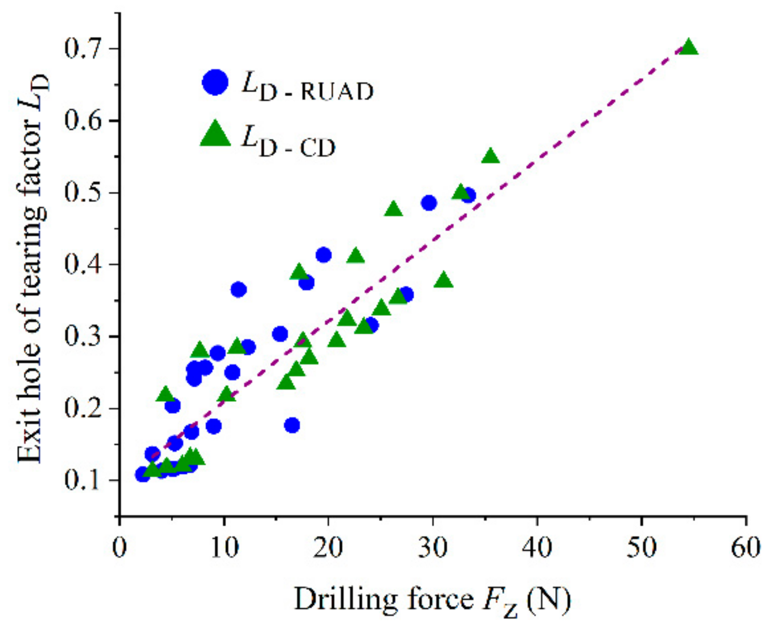
3.5. Tearing Factor of the Hole Exit

The tearing factor is frequently employed to quantify drilling damage to composite materials surrounding the entry or exit of the hole [3]. As shown in Figure 13, the tearing factor of the hole exit LD can be calculated as follows:
L D = D m D h D h ,
where Dm is the maximum diameter of the tearing area at the hole exit, and Dh is the actual drilled hole diameter of the SiCf/SiC composite.
The hole exit tearing factor is directly related to the drilling parameters (spindle speed, feed rate), and different processing methods (RUAD, CD) of the hole made by the tearing factor show different phenomena. Figure 14 depicts the development of the tearing factor of the hole exit LD at various spindle speeds and feed rates in RUAD and CD. When the feed rate vw and the spindle speed n increase from 10 to 50 mm/min and from 4000 to 20,000 rpm, respectively, the tearing factor of the hole exit LD is better in RUAD than in CD. When the spindle speed n is 4000 rpm and the feed rate vw is 10 mm/min, the tearing factor of the hole exit LD is 0.39 in CD and 0.36 in RUAD. In particular, throughout the experimental domain, the tearing factor of the hole exit LD increases from 0.1 to 0.5 in RUAD and from 0.11 to 0.7 in CD, as shown in Figure 14a,b. The morphology of the hole exit also illustrates that with the increment of spindle speed, the tearing area reduces for both RUAD and CD, while the increased feed rate can deteriorate the hole exit quality, which means an increase in the tearing area, as shown in Figure 15 and Figure 16. In the studied range of the parameters, the exit tearing factor in RUAD varies to a smaller extent compared to CD. Furthermore, RUAD results in smaller exit tear size throughout the entire range of drilling parameters, achieving a maximum reduction of 37.26% (n = 16,000 rpm, vw = 10 mm/min, A = 5 μm, f = 23.5 kHz) as shown in Figure 14c. The morphology of the hole exit also demonstrates the advantages of ultrasonic vibration in reducing the exit tearing, as shown in Figure 15c and Figure 16c.
As both the SiC matrix and the SiC fibers in SiCf/SiC composites are exceedingly hard and brittle, the exit tear during drilling is primarily caused by cracks generated under the drilling force and their extension to the hole exit. This paper describes the formation process of exit tearing in detail, as shown in Figure 17. The tear damage formation during the drilling of SiCf/SiC is similar to that during the drilling of the C/SiC composite, as reported by Feng et al. [21]. It mainly includes fiber-matrix interface debonding, fiber bending, and fiber breaking. When the diamond core drill reaches the bottom of the material, cracks occur at the fiber-matrix contact as a result of the drilling force, as shown in Figure 17a. The crack expands along the fiber-matrix interface until debonding. The hole exit is composed of fewer composite layers and thus has low support strength. The fiber is bent and deformed as the core drill proceeds toward the hole exit, further expanding the interface’s debonding length, as illustrated in Figure 17b. With further feeding of the core drill, the fibers continue to bend until breaking when the compressive stress from the drilling force exceeds the flexural strength of the fibers, eventually causing tearing at the hole exit, as shown in Figure 17c. The chip morphology of the SiCf/SiC composite after drilling through the material and the fiber fracture morphology at the edge of the chip reflect the state of the hole exit tear, as illustrated in Figure 17d.
The drilling force FZ is the key element influencing the degree of hole exit tearing. According to Figure 18, the drilling force and hole exit tearing are positively associated, meaning that the higher the drilling force, the bigger the hole exit tearing. This is similar to the results of Feng [20] and Chen [38]. As a result, RUAD effectively minimizes the drilling force, lowering the hole exit tearing factor.

4. Conclusions

This study proposes an innovative strategy for dry drilling of small holes in SiCf/SiC composites—dry rotary ultrasonic-assisted drilling (RUAD) using an orderly arranged brazed diamond core drill. We investigate the effect of tool life and wear on drilling accuracy during dry machining and the effects of processing parameters on drilling force, torque, surface roughness Sa of holes, and exit tearing. We also validated the benefits of RUAD with orderly arranged brazed diamond core drills for machining SiCf/SiC composites. The main conclusions are as follows.
(1) When the feed rate is 30 mm/min and the spindle speed is 12,000 rpm, the studied core drill made 102 holes during RUAD until failure. The diameters of the drilled holes ranged from 3.95 to 4.04 mm, whereas before hole 92, the maximum error in hole diameter was 0.03 mm, indicating a relatively high drilling accuracy for this process.
(2) RUAD and conventional drilling (CD) are compared using multiple parameters. Ultrasonic vibration changed the contact state and friction behavior between the core drill and SiCf/SiC workpiece, and the equivalent friction coefficient of dry RUAD is lower by 38% than that of CD. Furthermore, RUAD showed significantly lower drilling force and torque than CD as follows: the drilling force during RUAD is in the range of 2.25–33.40 N with a maximum reduction of 60.6%, and torque is in the range of 0.0024–0.02096 N m with a maximum reduction of 78.6%.
(3) Compared with CD, RUAD exhibits a smaller drilling force and a larger trajectory overlap region for the abrasive grains on the tool, which effectively reduces the surface roughness of holes and the exit tearing factor. At the tested parameters, the hole wall surface roughness Sa is 2.60–13.03 μm for RUAD and 2.91–19.03 μm for CD, RUAD can reduce the Sa up to 46.4%. The exit tearing factor LD is 0.1–0.5 for RUAD with a maximum reduction of 37.3%, while the tearing factor is 0.11–0.7 for CD.
(4) RUAD maintains high hole-making quality and improves the hole-making efficiency even at relatively high feed rates and low spindle speeds, thus extending the process domain for efficient and high-quality hole-making in SiCf/SiC composites.

Author Contributions

Conceptualization, J.H.; methodology, J.H. and N.Q.; software, P.X.; validation, J.H. and P.X.; formal analysis, J.H., H.S. and N.Q.; investigation, J.H.; resources, H.S. and N.Q.; data curation, J.H.; writing—original draft preparation, J.H. and N.Q.; writing—review and editing, H.S.; funding acquisition, H.S. and N.Q. All authors have read and agreed to the published version of the manuscript.

Funding

This research was funded by National Natural Science Foundation of China, (grant number 92060203); China Postdoctoral Science Foundation, (grant number 2021M701696); Outstanding Postdoctoral Program of Jiangsu Province, (grant number 2022ZB204); and Science Center for Gas Turbine Project, (grant number P2022-A-IV-002-001).

Institutional Review Board Statement

Not applicable.

Informed Consent Statement

Not applicable.

Data Availability Statement

Not applicable.

Acknowledgments

The authors would like to thank the CHEN Yurong from JITRI Institute of Precision Manufacturing for his kind assistance with the equipment.

Conflicts of Interest

The authors declare no conflict of interest.

References

  1. Annerino, A.; Lawson, M.; Gouma, P.I. Future Insights on High Temperature Ceramics and Composites for Extreme Environments. Int. J. Ceram. Eng. Sci. 2022, 4, 296–301. [Google Scholar] [CrossRef]
  2. Gao, T.; Zhang, Y.; Li, C.; Wang, Y.; Chen, Y.; An, Q.; Zhang, S.; Li, H.N.; Cao, H.; Ali, H.M.; et al. Fiber-Reinforced Composites in Milling and Grinding: Machining Bottlenecks and Advanced Strategies. Front. Mech. Eng. 2022, 17, 24. [Google Scholar] [CrossRef]
  3. Xing, Y.; Deng, J.; Zhang, G.; Wu, Z.; Wu, F. Assessment in Drilling of C/C-SiC Composites Using Brazed Diamond Drills. J. Manuf. Process. 2017, 26, 31–43. [Google Scholar] [CrossRef]
  4. Huang, B.; Wang, W.; Jiang, R.; Xiong, Y.; Liu, C. Experimental Study on Ultrasonic Vibration-Assisted Drilling Micro-Hole of SiCf/SiC Ceramic Matrix Composites. Int. J. Adv. Manuf. Technol. 2022, 120, 8031–8044. [Google Scholar] [CrossRef]
  5. Xiao, C.; Han, B. Grinding, Machining Morphological Studies on C/SiC Composites. J. Inst. Eng. India Ser. D 2018, 99, 209–215. [Google Scholar] [CrossRef]
  6. Garcia Luna, G.; Axinte, D.; Novovic, D. Influence of Grit Geometry and Fibre Orientation on the Abrasive Material Removal Mechanisms of SiC/SiC Ceramic Matrix Composites (CMCs). Int. J. Mach. Tools Manuf. 2020, 157, 103580. [Google Scholar] [CrossRef]
  7. Xu, J.; Li, C.; Chen, M.; Ren, F. A Comparison between Vibration Assisted and Conventional Drilling of CfFR/Ti6Al4V Stacks. Mater. Manuf. Process. 2019, 34, 1182–1193. [Google Scholar] [CrossRef]
  8. Liu, Y.; Zhang, R.; Li, W.; Wang, J.; Yang, X.; Cheng, L.; Zhang, L. Effect of Machining Parameter on Femtosecond Laser Drilling Processing on SiC/SiC Composites. Int. J. Adv. Manuf. Technol. 2018, 96, 1795–1811. [Google Scholar] [CrossRef]
  9. Zhang, Y.; Liu, D.; Zhang, W.; Zhu, H.; Huang, C. Hole Characteristics and Surface Damage Formation Mechanisms of C/SiC Composites Machined by Abrasive Waterjet. Ceram. Int. 2022, 48, 5488–5498. [Google Scholar] [CrossRef]
  10. Sheikh-Ahmad, J.Y. Hole Quality and Damage in Drilling Carbon/Epoxy Composites by Electrical Discharge Machining. Mater. Manuf. Process. 2016, 31, 941–950. [Google Scholar] [CrossRef]
  11. Li, Z.; Yuan, S.; Ma, J.; Shen, J.; Batako, A.D.L. Cutting Force and Specific Energy for Rotary Ultrasonic Drilling Based on Kinematics Analysis of Vibration Effectiveness. Chin. J. Aeronaut. 2021, 35, 376–387. [Google Scholar] [CrossRef]
  12. Ding, K.; Fu, Y.; Su, H.; Chen, Y.; Yu, X.; Ding, G. Experimental Studies on Drilling Tool Load and Machining Quality of C/SiC Composites in Rotary Ultrasonic Machining. J. Mater. Process. Technol. 2014, 214, 2900–2907. [Google Scholar] [CrossRef]
  13. Li, C.; Hu, Y.; Zhang, F.; Geng, Y.; Meng, B. Molecular Dynamics Simulation of Laser Assisted Grinding of GaN Crystals. Int. J. Mech. Sci. 2022, in press. [Google Scholar] [CrossRef]
  14. Zhang, R.; Li, W.; Liu, Y.; Wang, C.; Wang, J.; Yang, X.; Cheng, L. Machining Parameter Optimization of C/SiC Composites Using High Power Picosecond Laser. Appl. Surf. Sci. 2015, 330, 321–331. [Google Scholar] [CrossRef]
  15. Zhai, Z.; Wang, W.; Mei, X.; Li, M.; Cui, J.; Wang, F.; Pan, A. Effect of the Surface Microstructure Ablated by Femtosecond Laser on the Bonding Strength of Ebcs for SiC/SiC Composites. Opt. Commun. 2018, 424, 137–144. [Google Scholar] [CrossRef]
  16. Thongkaew, K.; Wang, J.; Li, W. An Investigation of the Hole Machining Processes on Woven Carbon-Fiber Reinforced Polymers (CFRPs) Using Abrasive Waterjets. Mach. Sci. Technol. 2019, 23, 19–38. [Google Scholar] [CrossRef]
  17. Wei, C.; Zhao, L.; Hu, D.; Ni, J. Electrical Discharge Machining of Ceramic Matrix Composites with Ceramic Fiber Reinforcements. Int. J. Adv. Manuf. Technol. 2013, 64, 187–194. [Google Scholar] [CrossRef]
  18. Sonia, P.; Jain, J.K.; Saxena, K.K. Influence of Ultrasonic Vibration Assistance in Manufacturing Processes: A Review. Mater. Manuf. Process. 2021, 36, 1451–1475. [Google Scholar] [CrossRef]
  19. Hocheng, H.; Tai, N.H.; Liu, C.S. Assessment of Ultrasonic Drilling of C/SiC Composite Material. Compos. Part A-Appl. Sci. Manuf. 2000, 31, 133–142. [Google Scholar] [CrossRef]
  20. Feng, P.; Wang, J.; Zhang, J.; Zheng, J. Drilling Induced Tearing Defects in Rotary Ultrasonic Machining of C/SiC Composites. Ceram. Int. 2017, 43, 791–799. [Google Scholar] [CrossRef]
  21. Wang, J.; Zhang, J.; Feng, P. Effects of Tool Vibration on Fiber Fracture in Rotary Ultrasonic Machining of C/SiC Ceramic Matrix Composites. Compos. Part B-Eng. 2017, 129, 233–242. [Google Scholar] [CrossRef]
  22. Wang, J.; Zhang, J.; Feng, P.; Guo, P. Experimental and Theoretical Investigation on Critical Cutting Force in Rotary Ultrasonic Drilling of Brittle Materials and Composites. Int. J. Mech. Sci. 2018, 135, 555–564. [Google Scholar] [CrossRef]
  23. Ding, K.; Li, Q.; Zhang, C. Experimental Studies on Material Removal Mechanisms in Ultrasonic Assisted Grinding of SiC Ceramics with a Defined Grain Distribution Brazed Grinding Wheel. Int. J. Adv. Manuf. Technol. 2021, 116, 3663–3676. [Google Scholar] [CrossRef]
  24. Wu, W.; Kuzu, A.; Stephenson, D.; Hong, J.; Bakkal, M.; Shih, A. Dry and Minimum Quantity Lubrication High-Throughput Drilling of Compacted Graphite Iron. Mach. Sci. Technol. 2018, 22, 652–670. [Google Scholar] [CrossRef]
  25. Hwang, T.W.; Evans, C.J.; Malkin, S. High Speed Grinding of Silicon Nitride with Electroplated Diamond Wheels, Part 1: Wear and Wheel Life. J. Manuf. Sci. Eng. 2000, 122, 42–50. [Google Scholar] [CrossRef]
  26. Yu, Y.Q.; Tie, X.R.; Zhang, G.Q.; Huang, G.Q.; Huang, H.; Xu, X.P. Comparison of Brazed and Sintered Diamond Tools for Grinding of Stone. Mater. Res. Innov. 2014, 18, S2–S869. [Google Scholar] [CrossRef]
  27. Liu, D.; Long, W.; Wu, M.; Qi, K.; Pu, J. Microstructure Evolution and Lifetime Extension Mechanism of Sn-Added Fe-Based Pre-Alloy Brazing Coating in Diamond Tools. Coatings 2019, 9, 364. [Google Scholar] [CrossRef] [Green Version]
  28. Chen, Z.; Xiao, B.; Wang, B. Optimum and Arrangement Technology of Abrasive Topography for Brazed Diamond Grinding Disc. Int. J. Refract. Met. Hard Mat. 2021, 95, 105455. [Google Scholar] [CrossRef]
  29. Wang, P.; Liu, F.; Wang, H.; Li, H.; Gou, Y. A Review of Third Generation SiC Fibers and SiCf/SiC Composites. J. Mater. Sci. Technol. 2019, 35, 2743–2750. [Google Scholar] [CrossRef]
  30. Razzell, A.G. Joining and Machining of Ceramic Matrix Composites. In Comprehensive Composite Materials; Elsevier: Amsterdam, The Netherlands, 2000; Volume 4, pp. 689–697. [Google Scholar]
  31. Dai, J.; Su, H.; Hu, H.; Yu, T.; Zhou, W.; Ding, W.; Ji, S.; Zheng, Y. The Influence of Grain Geometry and Wear Conditions on the Material Removal Mechanism in Silicon Carbide Grinding with Single Grain. Ceram. Int. 2017, 43, 11973–11980. [Google Scholar] [CrossRef]
  32. Justine, D.; Eduardo, S.; Nasrin, A.N. Fracture Behaviour of SiC/SiC Ceramic Matrix Composite at Room Temperature. J. Eur. Ceram. Soc. 2022, 42, 3156–3167. [Google Scholar]
  33. Chen, Y.; Su, H.; Qian, N.; He, J.; Gu, J.; Xu, J.; Ding, K. Ultrasonic Vibration-Assisted Grinding of Silicon Carbide Ceramics Based on Actual Amplitude Measurement: Grinding Force and Surface Quality. Ceram. Int. 2021, 47, 15433–15441. [Google Scholar] [CrossRef]
  34. Wu, B.; Zhao, B.; Ding, W.; Su, H. Investigation of the Wear Characteristics of Microcrystal Alumina Abrasive Wheels during the Ultrasonic Vibration-Assisted Grinding of Ptmcs. Wear 2021, 477, 203844. [Google Scholar] [CrossRef]
  35. Ding, K.; Fu, Y.; Su, H.; Cui, F.; Li, Q.; Lei, W.; Xu, H. Study on Surface/Subsurface Breakage in Ultrasonic Assisted Grinding of C/SiC Composites. Int. J. Adv. Manuf. Technol. 2017, 91, 3095–3105. [Google Scholar] [CrossRef]
  36. Khunt, C.P.; Makhesana, M.A.; Patel, K.M.; Mawandiya, B.K. Performance Assessment of Vegetable Oil-Based Minimum Quantity Lubrication (MQL) in Drilling. Mater. Today Proc. 2021, 44, 341–345. [Google Scholar] [CrossRef]
  37. Islam, S.; Yuan, S.; Li, Z. Mathematical Modeling and Experimental Studies on Axial Drilling Load for Rotary Ultrasonic Drilling of C/SiC Composites. Int. J. Adv. Manuf. Technol. 2020, 107, 1309–1326. [Google Scholar] [CrossRef]
  38. Zou, F.; Chen, J.; An, Q.; Cai, X.; Chen, M. Influences of Clearance Angle and Point Angle on Drilling Performance of 2D Cf/SiC Composites Using Polycrystalline Diamond Tools. Ceram. Int. 2020, 46, 4371–4380. [Google Scholar] [CrossRef]
Figure 1. The structure of 2D SiCf/SiC composites: (a) model of SiC fiber preform, (b) micro-morphology by SEM, (c) micro-structure along transverse fibers, (d) micro-structure along longitudinal fibers.
Crystals 12 01658 g001
Figure 2. An orderly arranged brazed diamond core drill, (a) the composition of tool, (b) the side abrasive of tool, (c) the top abrasive of tool.
Crystals 12 01658 g002
Figure 3. Photo of the machining center: (a) overall experimental setup, (b) features of RUAD.
Crystals 12 01658 g003
Figure 4. Ultrasonic amplitude testing device, (a) eddy current sensor, (b) dynamometer and amplitude measurement controller, (c) axial ultrasonic amplitude at 8000 rpm.
Crystals 12 01658 g004
Figure 5. Diagram of the machining process, (a) drilling process, (b) tip of tool, (c) side of the tool, (d) the single abrasive grain motion trajectory during RUAD and CD, and (e) grain motion trajectory at one revolution.
Crystals 12 01658 g005
Figure 6. The result of tool life test, (a) relationship between the diameter of hole and the number of holes, (b) relationship between force and the number of holes.
Crystals 12 01658 g006
Figure 7. Drilling force and torque signals.
Crystals 12 01658 g007
Figure 8. Influence of spindle speeds and feed rates on drilling force, (a) variation trend of drilling force, (b) reduction rate KF of drilling force.
Crystals 12 01658 g008
Figure 9. Effect of different machining parameters on torque, (a) variation trend of torque, (b) variation trend KM of torque reduction.
Crystals 12 01658 g009
Figure 10. Effect of machining parameters on friction coefficient with and without ultrasonic drilling process.
Crystals 12 01658 g010
Figure 11. Sa sampling method.
Crystals 12 01658 g011
Figure 12. Surface roughness and reduction rate effects of drilling parameters, (a) surface roughness variation trend in RUAD, (b) surface roughness variation trend in CD, and (c) reduction rate.
Crystals 12 01658 g012
Figure 13. Schematic of the tearing factor.
Crystals 12 01658 g013
Figure 14. Effect of different parameters on exit tearing factor and its reduction, (a) variation trend of exit hole of tearing factor in RUAD, (b) variation trend of exit hole of tearing factor in CD, and (c) reduction rate.
Crystals 12 01658 g014aCrystals 12 01658 g014b
Figure 15. The morphology of the hole exit tearing areas in RUAD with (a) n = 4000 rpm, vw = 10 mm/min; (b) n = 20,000 rpm, vw = 10 mm/min; (c) n = 4000 rpm, vw = 50 mm/min; (d) n = 20,000 rpm, vw = 50 mm/min.
Crystals 12 01658 g015
Figure 16. The morphology of the hole exit tearing areas in CD with (a) n = 4000 rpm, vw = 10 mm/min; (b) n = 20,000 rpm, vw = 10 mm/min; (c) n = 4000 rpm, vw = 50 mm/min; (d) n = 20,000 rpm, vw = 50 mm/min.
Crystals 12 01658 g016
Figure 17. Hole exit tearing damage formation process, (a) fiber-matrix interface debonding, (b) fiber bending, (c) fiber breaking, and (d) chip morphology.
Crystals 12 01658 g017aCrystals 12 01658 g017b
Figure 18. Drilling force versus hole exit tearing factor.
Crystals 12 01658 g018
Table 2. Experimental parameters of rotary ultrasonic dry drilling.
ParametersValue
Spindle speed n (r/min)4000, 8000, 12,000, 16,000, 20,000
Feed rate vw (mm/min)10, 20, 30, 40, 50
Ultrasonic frequency f (kHz)23.5
Amplitude A (μm)0, 5
CoolantDry drilling
Publisher’s Note: MDPI stays neutral with regard to jurisdictional claims in published maps and institutional affiliations.

