1. Introduction
Surface plasmon polaritons (SPP) exist at an interface of the metal and dielectric material, evanescently confined in the perpendicular direction [
1]. As a radiation dipole is located in the transient field of SPP, the energy of the radiation dipole can be transferred to SPP. The new recombination channel of dipoles can be expected to improve the emission efficiency of the emitter. It has been reported in the literature that through surface plasmon (SP)–quantum well (QW) coupling, the internal quantum efficiency (IQE) of nitride light-emitting diodes (LEDs) can be significantly improved [
2,
3,
4], and the efficiency droop can also be suppressed [
5]. However, SP-coupled LEDs still face many challenges in practical preparations. For example, due to the short penetration depth of the SP evanescent field, the effective distance of the SP–QW coupling is only tens of nanometers, which increases the difficulty of preparing practical devices [
6]. In addition, the absorption of metal material itself will also reduce the luminous efficiency of an SP-coupled LED [
7]. In order to overcome these problems, different SP-coupled LED structures are proposed [
4,
8,
9,
10]. For example, Lee et al. reported an SP-coupled LED with high density Al nanoparticles (NPs), whose SP coupling distance was shortened by dry etching a p-GaN layer [
4].
Although it can be well understood that the recombination rate of the radiation dipole can be significantly improved through SP coupling, the light extraction behavior of an SP-coupled deep-ultraviolet LED is theoretically less studied [
11]. A better understanding of the influence of SP coupling on the light extraction behavior of the device can enable us to design the structure of SP-coupled LED devices better. In this study, the extraction behavior of s- and p-polarized light with various zenith angles θ for an SP-coupled deep-ultraviolet LED is investigated numerically by a three-dimensional (3D) finite-difference time-domain (FDTD) simulation. The commercial software Lumerical FDTD Solutions is used for the simulation. First, the transmittance of s- and p-polarized light at different zenith angles θ is calculated and analyzed. Although the polarized light that is larger than the critical angle θ
c can be extracted due to the existence of Al NPs, the transmission intensity is very low due to the absorption of metals. Then, using the transverse-electric (TE) and transverse-magnetic (TM) spontaneous emission rates calculated based on the k-p perturbation method, the optical output intensity and extraction efficiency of the SP-coupled LED are calculated. The numerical results show that, compared with the conventional QW structure, the light output intensity of the SP-coupled LED structure is significantly improved, but the extraction efficiency is low without considering the lateral surface extraction and bottom reflection. The improvement of the luminous efficiency of the SP-coupled LED comes mainly from the significant improvement of the radiation recombination rate. In addition, the reasonable design of metal nanostructures can improve the extraction efficiency of SP-coupled LEDs.
2. Theoretical Model
The extraction behavior of s- and p-polarized light for the SP coupling LED is investigated by 3D FDTD simulation.
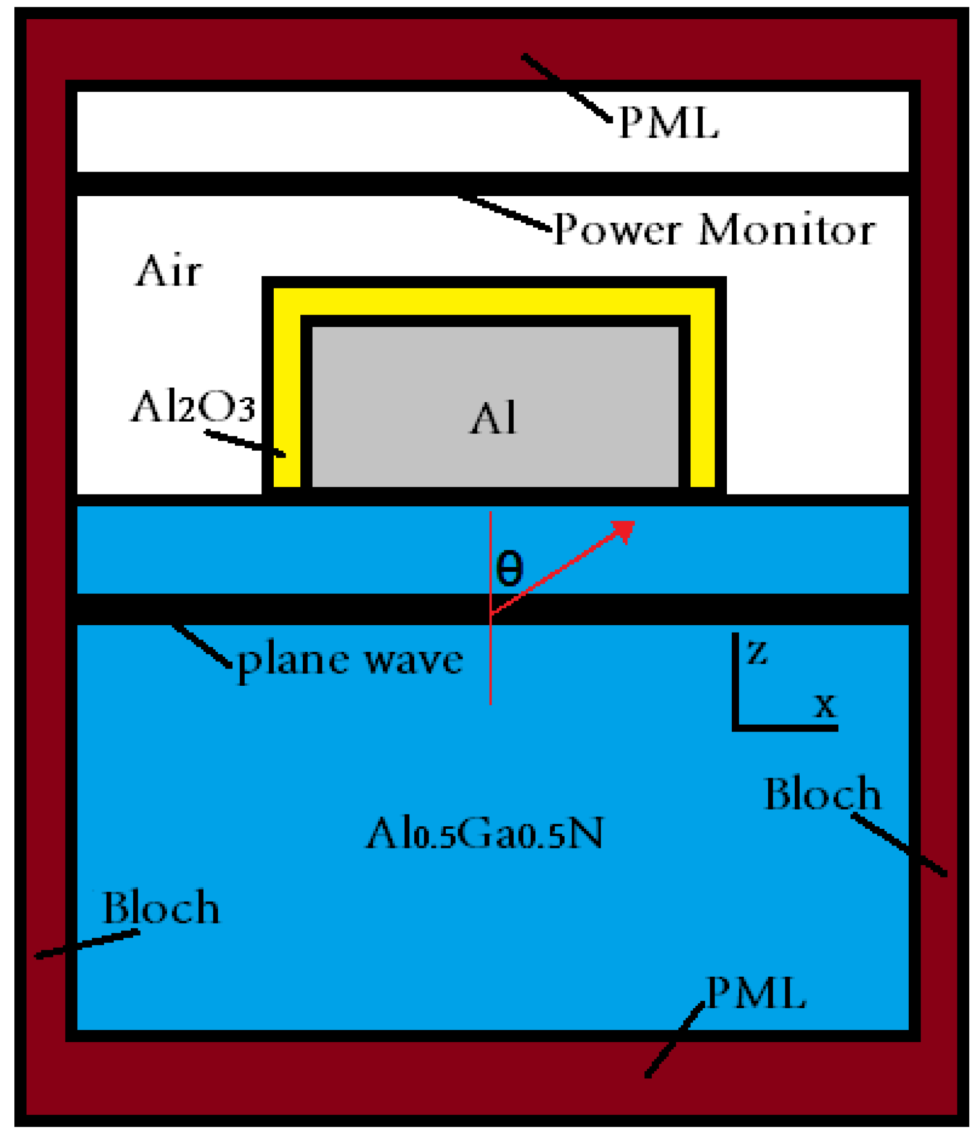
Figure 1 shows the schematic diagram of the 3D FDTD computational model for the SP-coupled LED. Periodically arranged cylindrical Al NPs with a height of 30 nm were placed on the Al
0.5Ga
0.5N layer. The duty cycle for periodically arranged Al NPs is set to 0.5. Taking into account the surface oxidation of Al NPs, a layer of Al
2O
3 with a thickness of 3 nm was arranged on the surface of Al NPs. The wavelength-dependent complex refractive index of Al
0.5Ga
0.5N is calculated by using the model dielectric function (MDF) [
12]. The perfectly matched layer (PML) boundary conditions are used at the top and bottom (i.e., x-y planes). Considering that Al NPs are arranged periodically in the X and Y directions, the Bloch boundary conditions are used on the four sides. The plane wave is used as the source shape. The propagation direction of polarized light is set in the x-z plane and illustrated by the zenith angle θ. Thus, the electric field of the s oscillating component is perpendicular to the x-z plane, while the electric field of the p-component is located in the x-z plane. The transmittance (T
s/p(θ)) of s- and p-polarized light in different emission directions can be obtained through the ‘power monitor’. It should be noted that the lateral surface extraction, bottom reflection, and packaging are not taken into consideration in the FDTD simulation.
In order to investigate the light output intensity of the SP-coupled LED, the TE- and TM-polarized spontaneous emission (SE) rates (
,
) are calculated by the k-p perturbation method [
13,
14]. Since the SE rate into the SPP mode is much greater than that into free space, only the SE spectrum into the SPP mode is considered in the calculation for the SP-coupled LED.
Figure 2 shows the TE- and TM-polarized SE spectrum of the conventional QW structure LED (c-LED) and SP-coupled LED (SP-LED). The quantum well structure consists of a 2 nm Al
0.35Ga
0.65N well layer and an 8 nm Al
0.5Ga
0.5N barrier layer. For the convenience of calculation, a 30 nm Al/3 nm-Al
2O
3 planar film is used in the SP-coupled LED. The distance
d between the QW and the Al film is set to 15 nm, 20 nm, and 25 nm. Note that the curve in
Figure 2b is discontinuous, which can be attributed to the electric field discontinuity obtained by the FDTD simulation. Then, the integrated intensity I(θ) of the output spectrum is calculated by the formula:
Here,
and
are the SE rates of the s- and p-components, which can be expressed as [
15]:
In addition, the ratio of luminous efficiency of both SP-LED and c-LED is defined as:
The light extraction efficiency (LEE) is defined as:
where S(θ) and P(θ) are the integral intensities of the SE spectra of the s- and p-components, respectively. Since the reflection at the bottom is not considered, the equation of formula (4) is divided by 2. It should be noted that the symmetry of rotation around the z-axis is assumed in the above calculation.
3. Results and Discussion
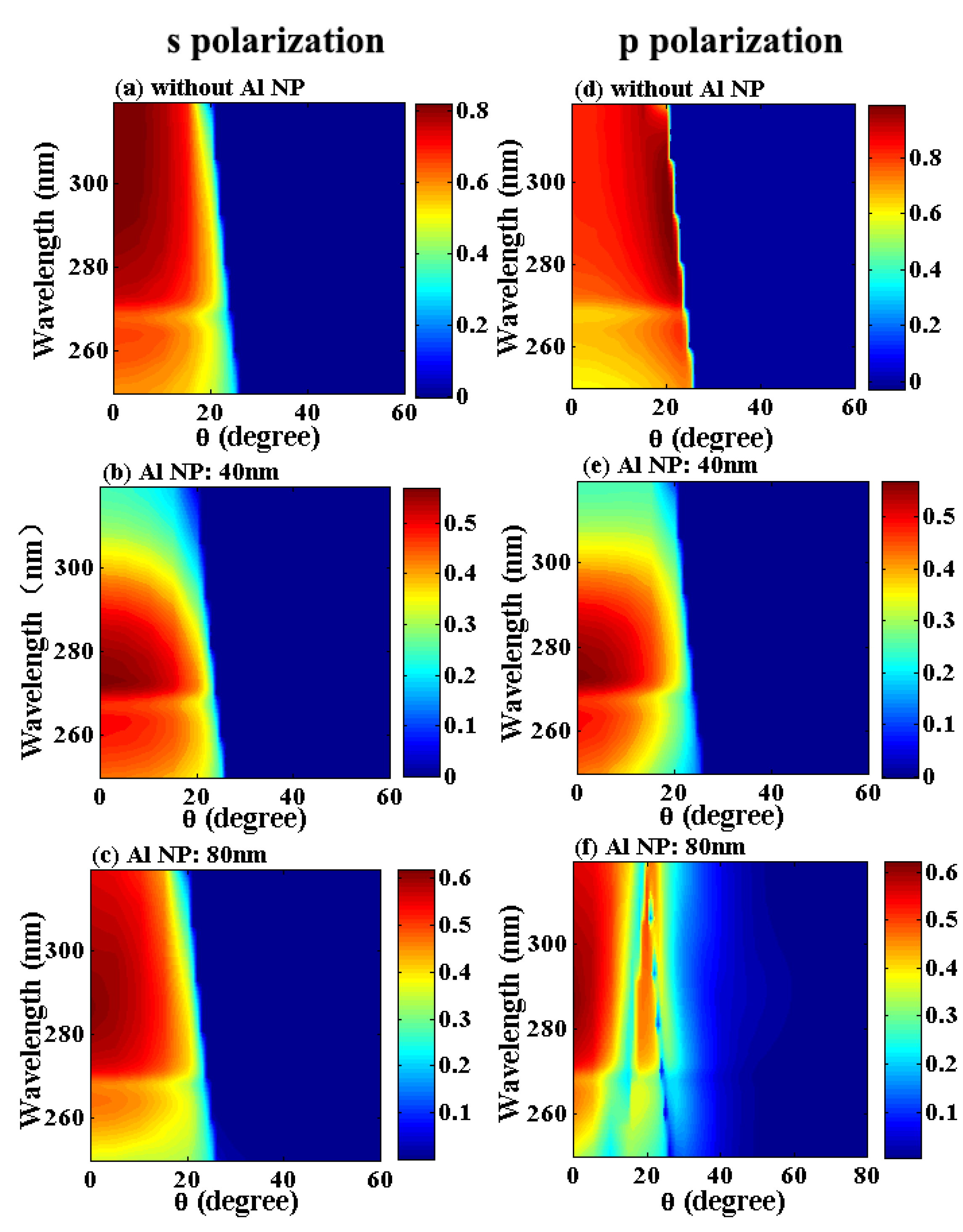
Figure 3 shows the transmission spectra of c-LED and SP-LED as a function of θ for s- and p-polarizations. For SP-LED, the diameter of Al NPs is set to 40 nm and 80 nm, respectively. Due to the internal total reflection, a boundary composed of critical angles can be clearly seen from the figure. In the wavelength range of 260–300 nm, the critical angle decreases slightly from 24° to 21° due to the increase of the AlGaN refractive index. Compared with the transmittance of c-LED, the transmittance of SP-LED is lower due to the absorption of Al NPs [
7]. For c-LED, the maximum transmittances of s- and p-polarizations are located at (θ
= 0°,
λ = 319 nm) and (θ
= 20°,
λ = 298 nm), respectively, while that for SP-LED appears in the same position. As the diameter of Al NPs increased from 40 nm to 80 nm, the position of the maximum transmittance changed from (θ = 0°,
λ = 273 nm) to (θ = 0°,
λ = 286 nm), and the transmission intensity also increased. In particular, for SP-LED with 80 nm Al NPs, excepting the fact that the secondary maximum transmittance of the p-polarization can be observed at (θ = 20°,
λ = 307 nm), the transmission spectrum can still be obviously observed when the incident angle is greater than the critical angle. The situation has not happened for SP-LED with 40 nm Al NPs. To illustrate this difference, we simulated the steady-state electric field intensity distribution of the p-polarization in the x-z plane and y-z plane at (θ = 24°,
λ = 291 nm), as shown in
Figure 4. From this figure, it can be observed that the proportion of the field distributed in Al NPs for SP-LED with 40 nm Al NPs is significantly larger than that for SP-LED with 80 nm Al NPs. Therefore, for smaller Al NP structures, Al NPs will absorb more transmitted light, resulting in almost zero transmittance on the right of the boundary in
Figure 3e. Note that the electric field intensity distribution in
Figure 4a,c is not a line symmetry. This can be attributed to the fact that the plane wave propagates along θ = 24°.
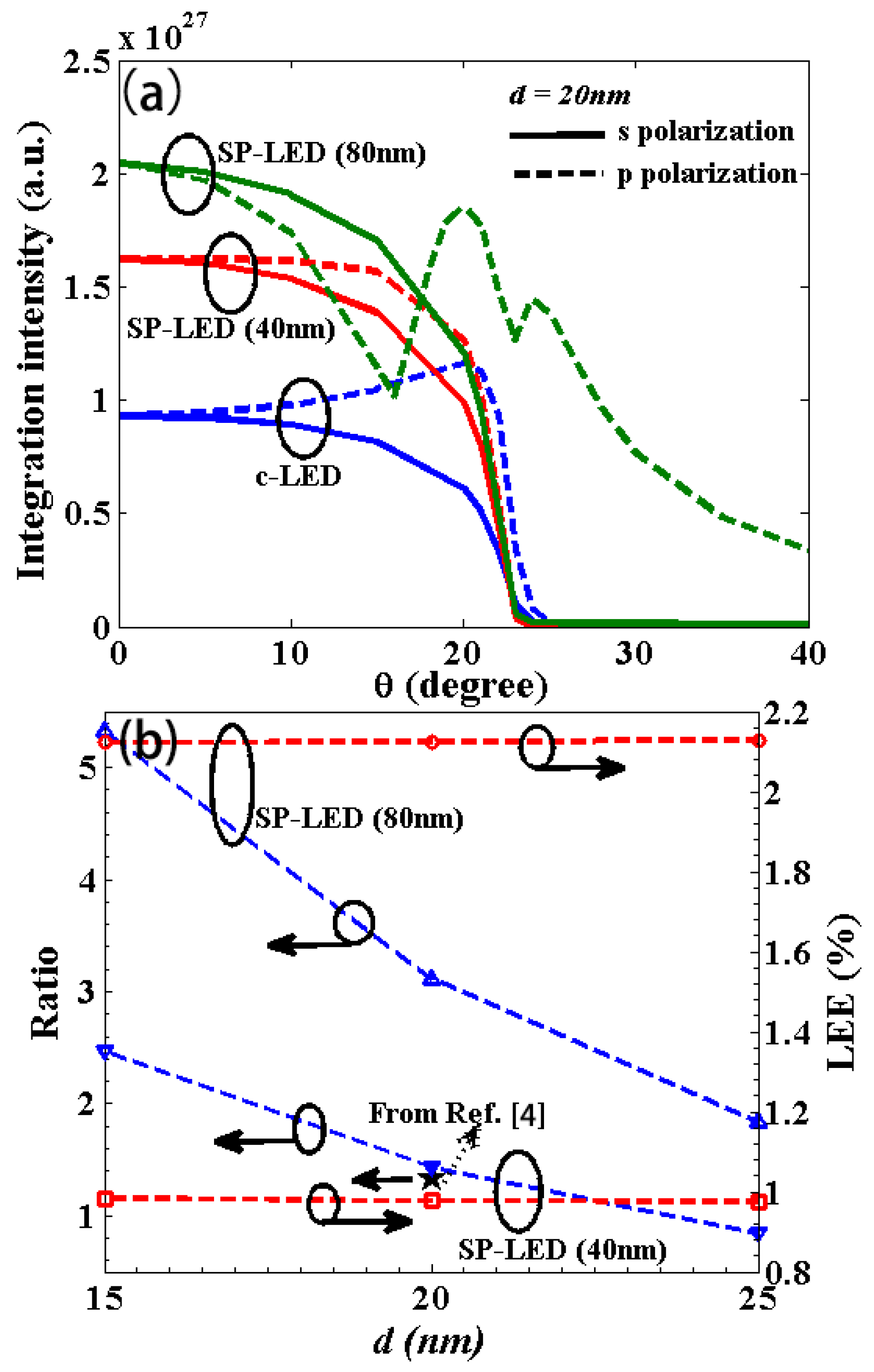
Figure 5a shows the integrated intensity I(θ) of the output spectrum with s- and p-polarizations as a function of θ for c-LED and SP-LED. The Al-QW coupling distance
d is set as 20 nm. For c-LED, the integral intensity of the s-polarization decreases monotonically with θ, while that of the p-polarization has a maximum at θ = 20°. For SP-LED, the maximum values of the integral intensity of both s- and p-polarizations are located at θ = 0°. In addition, the p-polarization integral intensity of SP-LED with 80 nm Al NPs has two extreme values at θ = 20° and θ = 24°. As can be seen from
Figure 3f, the 80 nm Al NP structure has two strong transmission regions on both sides of the critical angle, and the corresponding transmittance is significantly greater than that of the 40 nm Al NP structure due to the reduction of the absorption of Al NPs. Therefore, for the 80 nm Al NP structure, there are two extreme values at θ = 20° and θ = 24°. Compared with c-LED, the integral intensity of SP-LED has been significantly improved, especially SP-LED with 80 nm Al NPs.
Figure 5b shows the ratio of luminous efficiency of both SP-LED and c-LED and the light extraction efficiency of SP-LED. As the Al-QW coupling distance decreases from
d = 25 nm to
d = 15 nm, the ratio for SP-LED with 40 nm Al NPs increases from 0.84 to 2.47, while the ratio for SP-LED with 80 nm Al NPs increases from 1.83 to 5.33. The calculated result is basically consistent with the experimental result of the AlGaN-based LED with 40 nm Al NPs reported in the literature [
4]. Compared with the calculated LEE (2.61%) for c-LED, the LEE for the 40 nm and 80 nm Al NPs structures is lower, only ~0.98% and ~2.12%. In addition, for the 40 nm Al NPs structure, with the increase of the Al NP height from 30 nm to 120 nm, the LEE decreases from ~0.98% to ~0.71% due to metal absorption. Similarly, when the duty cycle is increased from 0.5 to 0.6, the LEE is reduced to ~0.68%. It should be noted that the calculated LEE assumes the symmetry of rotation around the z-axis. Due to the large spacing between Al NPs in some directions, the actual light extraction efficiency should be smaller, especially for the 80 nm Al NPs structure. For example, after rotating 45° around the z-axis for the plane wave propagation direction, the LEE of the 40 nm Al NPs structure and 80 nm Al NPs structure is calculated to be ~0.97% and ~1.24% according to formula (4).
By comparing the LEE and integral intensity of c-LED and SP-LED, it can be inferred that the increase of luminous intensity for SP-LED with Al NPs is mainly due to the increase of the electron-hole radiation recombination rate caused by SP coupling, rather than the improvement of LEE. Nevertheless, it can also be observed that the LEE of SP-LED with 80 nm Al NPs is significantly improved as compared to that of SP-LED with 40 nm Al NPs. It should be noted that further increasing the transverse size of Al NPs cannot improve the LEE of SP-LED due to the decrease of transmittance in the investigated wavelength range. In addition, the lateral surface extraction and bottom reflection are not considered in our calculation, which will also significantly affect the light extraction efficiency. For example, Wang et al. reported that the light extraction from the lateral surface gradually became dominant by reducing the propagation path [
15]. Therefore, the reasonable structural design of SP-LED with Al NPs can be expected to improve the LEE.
4. Conclusions
In summary, the extraction behavior of s- and p-polarizations in different propagation directions for the SP coupling LED is investigated by 3D FDTD simulation. For SP-LED with Al NPs, the maximum transmittances of s- and p-polarizations are located at θ = 0°, while the corresponding wavelength of the maximum transmittance shifts red with the increase of the diameter of Al NPs. In particular, as the incident angle is greater than the critical angle, the transmission spectrum of p-polarization for the AlGaN-based LED with larger diameter Al NPs can also be obviously observed due to the reduction of the metal absorption. Compared with the conventional Al0.35Ga0.65N/Al0.5Ga0.5N QW structure, the luminous efficiency of the SP-coupled LED can be significantly improved. However, the LEE of the Al0.35Ga0.65N/Al0.5Ga0.5N QW structure with 40 nm (80 nm) Al NPs is not greater than ~0.98% (~2.12%), lower than 2.61% for c-LED without SP coupling. Note that the lateral surface extraction and bottom reflection are not considered in the calculation. The lower LEE can be attributed to the absorption of Al NPs. Thus, it is necessary to reasonably design the structure of the SP-coupled LED to improve its LEE.


