
Optomechanically Induced Transparency and Slow–Fast Light Effect in Hybrid Cavity Optomechanical Systems


Abstract
:1. Introduction
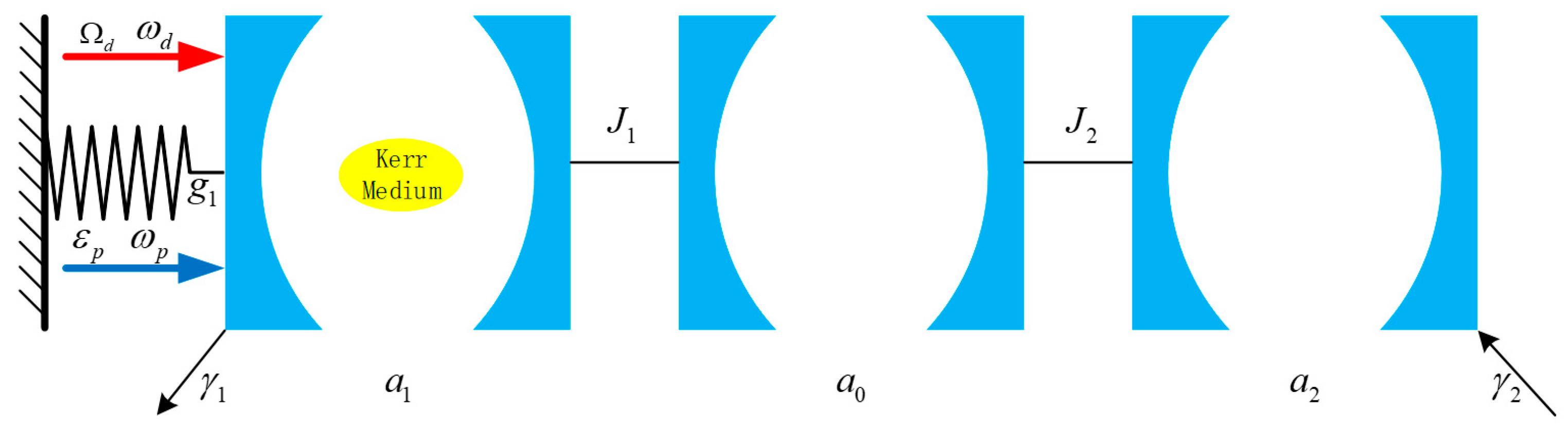
2. Model
3. Quantum Dynamics and Fluctuations
4. The Multi-Transparency Windows of the Output Field for the Hybrid Optomechanical System
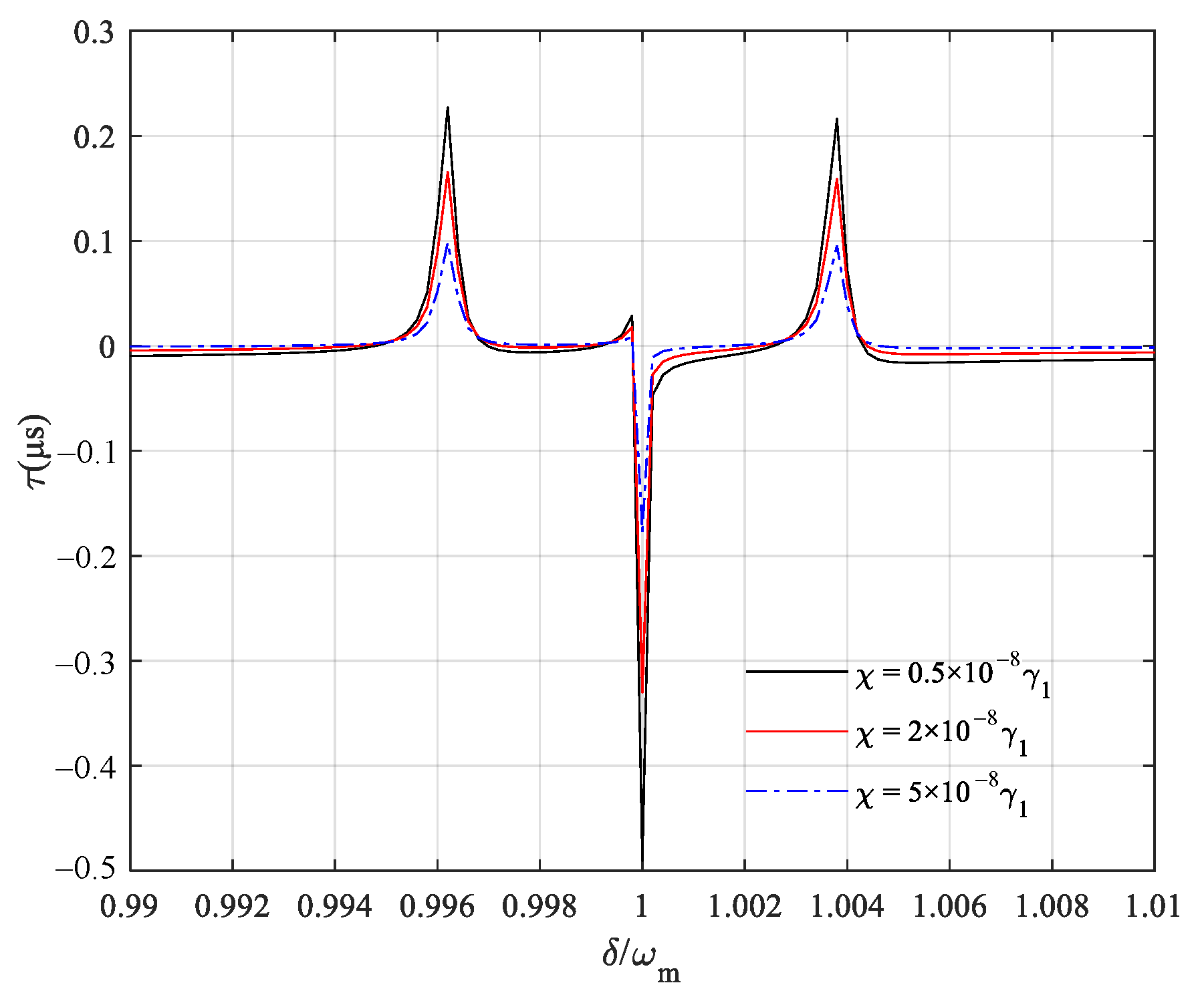
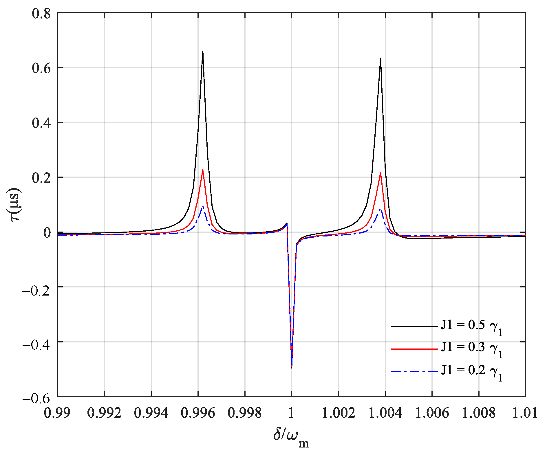
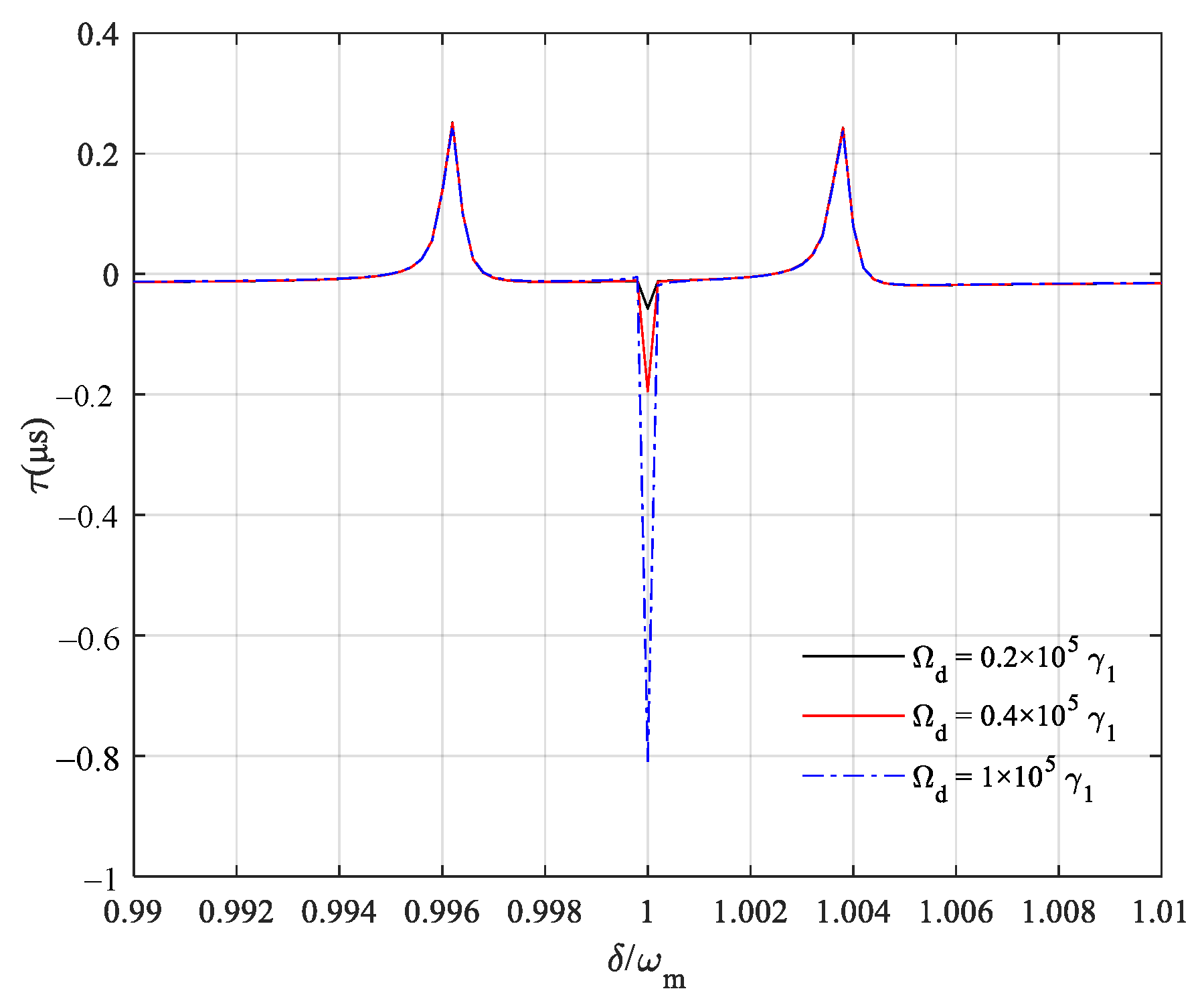
5. Slow–Fast Light Effect of the Output Field
6. Conclusions
Author Contributions
Funding
Institutional Review Board Statement
Informed Consent Statement
Data Availability Statement
Conflicts of Interest
References
- Aspelmeyer, M.; Kippenberg, T.J.; Marquardt, F. Cavity optomechanics. Rev. Mod. Phys. 2013, 86, 1391–1452. [Google Scholar] [CrossRef]
- Marquardt, F.; Chen, J.P.; Clerk, A.A.; Girvin, S.M. Quantum theory of cavity-assisted sideband cooling of mechanical motion. Phys. Rev. Lett. 2007, 99, 093902. [Google Scholar] [CrossRef] [PubMed] [Green Version]
- Wilson-Rae, I.; Nooshi, N.; Zwerger, W.; Kippenberg, T.J. Theory of ground state cooling of a mechanical oscillator using dynamical backaction. Phys. Rev. Lett. 2007, 99, 093901. [Google Scholar] [CrossRef] [Green Version]
- He, B.; Yang, L.; Lin, Q.; Xiao, M. Radiation pressure cooling as a quantum dynamical process. Phys. Rev. Lett. 2017, 118, 233604. [Google Scholar] [CrossRef] [PubMed] [Green Version]
- Lau, H.K.; Clerk, A.A. Ground-state cooling and high-fidelity quantum transduction via parametrically driven bad-cavity optomechanics. Phys. Rev. Lett. 2020, 124, 103602. [Google Scholar] [CrossRef] [Green Version]
- Vitali, D.; Gigan, S.; Ferreira, A.; Böhm, H.R.; Tombesi, P.; Guerreiro, A.; Vedral, V.; Zeilinger, A.; Aspelmeyer, M. Optomechanical entanglement between a movable mirror and a cavity field. Phys. Rev. Lett. 2007, 98, 030405. [Google Scholar] [CrossRef] [Green Version]
- Yan, X.B.; Deng, Z.J.; Tian, X.D.; Wu, J.H. Entanglement optimization of filtered output fields in cavity optomechanics. Opt. Express 2019, 27, 24393–24402. [Google Scholar] [CrossRef] [Green Version]
- Rabl, P. Photon blockade effect in optomechanical systems. Phys. Rev. Lett. 2011, 107, 063601. [Google Scholar] [CrossRef]
- Liao, J.Q.; Nori, F. Photon blockade in quadratically coupled optomechanical systems. Phys. Rev. A 2013, 88, 023853. [Google Scholar] [CrossRef] [Green Version]
- Xu, X.W.; Li, Y.J.; Liu, Y.X. Photon-induced tunneling in optomechanical systems. Phys. Rev. A 2013, 87, 025803. [Google Scholar] [CrossRef] [Green Version]
- Wang, D.Y.; Bai, C.H.; Liu, S.T.; Wang, H.F. Distinguishing photon blockade in a PT-symmetric optomechanical system. Phys. Rev. A 2019, 99, 043818. [Google Scholar] [CrossRef] [Green Version]
- Børkje, K. Critical quantum fluctuations and photon antibunching in optomechanical systems with large single-photon cooperativity. Phys. Rev. A 2020, 101, 053833. [Google Scholar] [CrossRef]
- Wang, D.Y.; Bai, C.H.; Liu, S.T.; Zhang, S.; Wang, H.F. Photon blockade in a double-cavity optomechanical system with nonreciprocal coupling. New J. Phys. 2020, 22, 093006. [Google Scholar] [CrossRef]
- Liu, J.S.; Yang, J.Y.; Liu, H.Y.; Zhu, A.D. Photon blockade by enhancing coupling via a nonlinear medium. Opt. Express 2020, 28, 18397–18406. [Google Scholar] [CrossRef] [PubMed]
- Wang, D.Y.; Bai, C.H.; Xing, Y.; Liu, S.T.; Zhang, S.; Wang, H.F. Enhanced photon blockade via driving a trapped Λ-type atom in a hybrid optomechanical system. Phys. Rev. A 2020, 102, 043705. [Google Scholar] [CrossRef]
- Zhu, J.; Ozdemir, S.K.; Xiao, Y.F.; Li, L.; He, L.; Chen, D.R.; Yang, L. On-chip single nanoparticle detection and sizing by mode splitting in an ultrahigh-Q microresonator. Nat. Photon. 2010, 4, 46–49. [Google Scholar] [CrossRef]
- Li, J.J.; Zhu, K.D. All-optical mass sensing with coupled mechanical resonator systems. Phys. Rep. 2013, 525, 223–254. [Google Scholar] [CrossRef]
- Liu, F.; Alaie, S.; Leseman, Z.C.; Hossein-Zadeh, M. Sub-pg mass sensing and measurement with an optomechanical oscillator. Opt. Express 2013, 21, 19555–19567. [Google Scholar] [CrossRef]
- Jing, H.; Özdemir, S.K.; Lü, X.Y.; Zhang, J.; Yang, L.; Nori, F. PT-symmetric phonon laser. Phys. Rev. Lett. 2014, 113, 053604. [Google Scholar] [CrossRef] [Green Version]
- Jing, H.; Özdemir, S.K.; Geng, Z.; Zhang, J.; Lü, X.Y.; Peng, B.; Yang, L.; Nori, F. Optomechanically-induced transparency in parity-time-symmetric microresonators. Sci. Rep. 2015, 5, 9663. [Google Scholar] [CrossRef]
- Zhang, X.Y.; Zhou, Y.H.; Guo, Y.Q.; Yi, X.X. Double optomechanically induced transparency and absorption in parity-time-symmetric optomechanical systems. Phys. Rev. A 2018, 98, 033832. [Google Scholar] [CrossRef]
- Li, W.L.; Jiang, Y.F.; Li, C.; Song, H.S. Parity-time-symmetry enhanced optomechanically-induced-transparency. Sci. Rep. 2016, 6, 31095. [Google Scholar] [CrossRef] [PubMed]
- Zhang, X.Y.; Guo, Y.Q.; Pei, P.; Yi, X.X. Optomechanically induced absorption in parity-time-symmetric optomechanical systems. Phys. Rev. A 2017, 95, 063825. [Google Scholar] [CrossRef]
- Xiao, X.; Liao, Q.H.; Zhou, N.R.; Liu, Y.C. Tunable optical second-order sideband effects in a parity-time symmetric optomechanical system. Sci. China-Phys. Mech. Astron. 2020, 63, 1–8. [Google Scholar]
- Yan, X.B. Optomechanically induced transparency and gain. Phys. Rev. A 2020, 101, 043820. [Google Scholar] [CrossRef]
- Manipatruni, S.; Robinson, J.T.; Lipson, M. Optical nonreciprocity in optomechanical structures. Phys. Rev. Lett. 2009, 102, 213903. [Google Scholar] [CrossRef] [PubMed] [Green Version]
- Qu, K.; Agarwal, G.S. Fano resonances and their control in optomechanics. Phys. Rev. A 2013, 87, 063813. [Google Scholar] [CrossRef] [Green Version]
- Ruesink, F.; Mathew, J.P.; Miri, M.A.; Alù, A.; Verhagen, E. Optical circulation in a multimode optomechanical resonator. Nat. Commun. 2018, 9, 1–6. [Google Scholar] [CrossRef] [Green Version]
- Lai, D.G.; Wang, X.; Qin, W.; Hou, B.P.; Nori, F.; Liao, J.Q. Tunable optomechanically induced transparency by controlling the dark-mode effect. Phys. Rev. A 2020, 102, 023707. [Google Scholar] [CrossRef]
- Chang, D.E.; Safavi-Naeini, A.H.; Hafezi, M.; Painter, O. Slowing and stopping light using an optomechanical crystal array. New J. Phys. 2011, 13, 023003. [Google Scholar] [CrossRef]
- Monroe, C. Quantum information processing with atoms and photons. Nature 2002, 416, 238–246. [Google Scholar] [CrossRef]
- Braunstein, S.L.; Van Loock, P. Quantum information with continuous variables. Rev. Mod. Phys. 2005, 77, 513. [Google Scholar] [CrossRef] [Green Version]
- Agarwal, G.S.; Huang, S. Electromagnetically induced transparency in mechanical effects of light. Phys. Rev. A 2010, 81, 041803. [Google Scholar] [CrossRef] [Green Version]
- Huang, S.; Agarwal, G.S. Electromagnetically induced transparency from two-phonon processes in quadratically coupled membranes. Phys. Rev. A 2011, 83, 023823. [Google Scholar] [CrossRef] [Green Version]
- Weis, S.; Rivière, R.; Deléglise, S.; Gavartin, E.; Arcizet, O.; Schliesser, A.; Kippenberg, T.J. Optomechanically induced transparency. Science 2010, 330, 1520–1523. [Google Scholar] [CrossRef] [PubMed] [Green Version]
- Safavi-Naeini, A.H.; Alegre, T.P.M.; Chan, J.; Eichenfield, M.; Winger, M.; Lin, Q.; Hill, J.T.; Chang, D.E.; Painter, O. Electromagnetically induced transparency and slow light with optomechanics. Nature 2011, 472, 69–73. [Google Scholar] [CrossRef] [PubMed] [Green Version]
- Li, X.Y.; Nie, W.J.; Chen, A.X.; Lan, Y.H. Effect of the mechanical oscillator on the optical-response properties of an optical trimer system. Phys. Rev. A 2018, 98, 053848. [Google Scholar] [CrossRef]
- Peng, J.X.; Chen, Z.; Yuan, Q.Z.; Feng, X.L. Optomechanically induced transparency in a Laguerre-Gaussian rotational-cavity system and its application to the detection of orbital angular momentum of light fields. Phys. Rev. A 2019, 99, 043817. [Google Scholar] [CrossRef]
- Han, Y.; Cheng, J.; Zhou, L. Electromagnetically induced transparency in a cavity optomechanical system with an atomic medium. J. Phys. B At. Mol. Opt. Phys. 2011, 44, 165505. [Google Scholar] [CrossRef]
- Gu, K.H.; Yan, D.; Wang, X.; Zhang, M.L.; Yin, J.Z. Hybrid electromagnetically-optomechanically induced transparency in an atom-assisted optomechanical system. J. Phys. B At. Mol. Opt. Phys. 2019, 52, 105502. [Google Scholar] [CrossRef]
- Han, C.M.; Wang, X.; Chen, H.; Li, H.R. Tunable slow and fast light in an atom-assisted optomechanical system with a mechanical pump. Opt. Commun. 2020, 456, 124605. [Google Scholar] [CrossRef]
- Liao, Q.H.; Xiao, X.; Nie, W.J.; Zhou, N.R. Transparency and tunable slow-fast light in a hybrid cavity optomechanical system. Opt. Express 2020, 28, 5288–5305. [Google Scholar] [CrossRef]
- Liu, J.H.; Yu, Y.F.; Zhang, Z.M. Nonreciprocal transmission and fast-slow light effects in a cavity optomechanical system. Opt. Express 2019, 27, 15382–15390. [Google Scholar] [CrossRef]
- Boyd, R.W.; Gauthier, D.J. Controlling the velocity of light pulses. Science 2009, 326, 1074–1077. [Google Scholar] [CrossRef] [Green Version]
- Jiao, Y.; Lü, H.; Qian, J.; Li, Y.; Jing, H. Nonlinear optomechanics with gain and loss: Amplifying higher-order sideband and group delay. New J. Phys. 2016, 18, 083034. [Google Scholar] [CrossRef]
- Jiao, Y.F.; Lu, T.X.; Jing, H. Optomechanical second-order sidebands and group delays in a Kerr resonator. Phys. Rev. A 2018, 97, 013843. [Google Scholar] [CrossRef] [Green Version]
- Lü, H.; Jiang, Y.J.; Wang, Y.Z.; Jing, H. Optomechanically induced transparency in a spinning resonator. Photonics Res. 2017, 5, 367–371. [Google Scholar] [CrossRef]
- Zimmer, F.; Fleischhauer, M. Sagnac interferometry based on ultraslow polaritons in cold atomic vapors. Phys. Rev. Lett. 2004, 92, 253201. [Google Scholar] [CrossRef] [Green Version]
- Shahriar, M.S.; Pati, G.S.; Tripathi, R.; Gopal, V.; Messall, M.; Salit, K. Ultrahigh enhancement in absolute and relative rotation sensing using fast and slow light. Phys. Rev. A 2007, 75, 053807. [Google Scholar] [CrossRef] [Green Version]
- Wang, B.; Liu, Z.X.; Kong, C.; Xiong, H.; Wu, Y. Mechanical exceptional-point-induced transparency and slow light. Opt. Express 2019, 27, 8069–8080. [Google Scholar] [CrossRef]
- Ziauddin; Rahmatullah; Hussain, A.; Abbas, M. Double transparency with slow and fast light in an optomechanical system. Opt. Commun. 2020, 461, 125284. [Google Scholar] [CrossRef]
- Kumar, T.; Bhattacherjee, A.B.; Mohan, M. Dynamics of a movable micromirror in a nonlinear optical cavity. Phys. Rev. A 2010, 81, 013835. [Google Scholar] [CrossRef] [Green Version]
- Huang, S.; Agarwal, G.S. Enhancement of cavity cooling of a micromechanical mirror using parametric interactions. Phys. Rev. A 2009, 79, 013821. [Google Scholar] [CrossRef] [Green Version]
- Farman, F.; Bahrampour, A.R. Effects of optical parametric amplifier pump phase noise on the cooling of optomechanical resonators. J. Opt. Soc. Am. B 2013, 30, 1898–1904. [Google Scholar] [CrossRef]
- Shahidani, S.; Naderi, M.H.; Soltanolkotabi, M.; Barzanjeh, S. Steady-state entanglement, cooling, and tristability in a nonlinear optomechanical cavity. J. Opt. Soc. Am. B 2014, 31, 1087–1095. [Google Scholar] [CrossRef] [Green Version]
- Li, L.; Nie, W.J.; Chen, A.X. Transparency and tunable slow and fast light in a nonlinear optomechanical cavity. Sci. Rep. 2016, 6, 35090. [Google Scholar] [CrossRef] [Green Version]
- Shahidani, S.; Naderi, M.H.; Soltanolkotabi, M. Control and manipulation of electromagnetically induced transparency in a nonlinear optomechanical system with two movable mirrors. Phys. Rev. A 2013, 88, 053813. [Google Scholar] [CrossRef] [Green Version]
- Genes, C.; Vitali, D.; Tombesi, P.; Gigan, S.; Aspelmeyer, M. Ground-state cooling of a micromechanical oscillator: Comparing cold damping and cavity-assisted cooling schemes. Phys. Rev. A 2008, 77, 033804. [Google Scholar] [CrossRef] [Green Version]
- Giovannetti, V.; Vitali, D. Phase-noise measurement in a cavity with a movable mirror undergoing quantum Brownian motion. Phys. Rev. A 2001, 63, 023812. [Google Scholar] [CrossRef] [Green Version]
- Xiong, H.; Si, L.G.; Zheng, A.S.; Yang, X.X.; Wu, Y. Higher-order sidebands in optomechanically induced transparency. Phys. Rev. A 2012, 86, 013815. [Google Scholar] [CrossRef] [Green Version]
- Liu, Z.H.; Lai, Y.C.; Matías, M.A. Universal scaling of Lyapunov exponents in coupled chaotic oscillators. Phys. Rev. E 2003, 67, 045203. [Google Scholar] [CrossRef] [PubMed] [Green Version]
- DeJesus, E.X.; Kaufman, C. Routh-Hurwitz criterion in the examination of eigenvalues of a system of nonlinear ordinary differential equations. Phys. Rev. A 1987, 35, 5288–5290. [Google Scholar] [CrossRef] [Green Version]
- Zhang, J.Q.; Li, Y.; Feng, M.; Xu, Y. Precision measurement of electrical charge with optomechanically induced transparency. Phys. Rev. A 2012, 86, 053806. [Google Scholar] [CrossRef] [Green Version]
- Massel, F.; Heikkilä, T.T.; Pirkkalainen, J.M.; Cho, S.U.; Saloniemi, H.; Hakonen, P.J.; Sillanpää, M.A. Microwave amplification with nanomechanical resonators. Nature 2011, 480, 351–354. [Google Scholar] [CrossRef] [PubMed] [Green Version]
- Zhao, X.H.; Hou, B.P.; Liu, L.; Zhao, Y.H.; Zhao, M.M. Cross-Kerr effect in a parity-time symmetric optomechanical system. Opt. Express 2018, 26, 18043–18054. [Google Scholar] [CrossRef] [PubMed]


Publisher’s Note: MDPI stays neutral with regard to jurisdictional claims in published maps and institutional affiliations. |
© 2021 by the authors. Licensee MDPI, Basel, Switzerland. This article is an open access article distributed under the terms and conditions of the Creative Commons Attribution (CC BY) license (https://creativecommons.org/licenses/by/4.0/).
Share and Cite
Liao, Q.; Bao, W.; Xiao, X.; Nie, W.; Liu, Y. Optomechanically Induced Transparency and Slow–Fast Light Effect in Hybrid Cavity Optomechanical Systems. Crystals 2021, 11, 698. https://doi.org/10.3390/cryst11060698
Liao Q, Bao W, Xiao X, Nie W, Liu Y. Optomechanically Induced Transparency and Slow–Fast Light Effect in Hybrid Cavity Optomechanical Systems. Crystals. 2021; 11(6):698. https://doi.org/10.3390/cryst11060698
Chicago/Turabian StyleLiao, Qinghong, Weida Bao, Xing Xiao, Wenjie Nie, and Yongchun Liu. 2021. "Optomechanically Induced Transparency and Slow–Fast Light Effect in Hybrid Cavity Optomechanical Systems" Crystals 11, no. 6: 698. https://doi.org/10.3390/cryst11060698