Next Article in Journal
Atomic Insights into Fracture Characteristics of Twisted Tri-Layer Graphene
Previous Article in Journal
NPG–TRIS Thermal Storage System. Quantification of the Limiting Processes: Sublimation and Water’s Adsorption
 
 
Correction published on 29 September 2022, see Crystals 2022, 12(10), 1384.
Article

General View of Rhenium-Rich Particles along Defect Grain Boundaries Formed in Nickel-Based Single-Crystal Superalloy Turbine Blades: Formation, Dissolution and Comparison with Other Phases

School of Metallurgy and Materials, University of Birmingham, Birmingham B15 2TT, UK
*
Author to whom correspondence should be addressed.
Crystals 2021, 11(10), 1201; https://doi.org/10.3390/cryst11101201
Submission received: 10 September 2021 / Revised: 29 September 2021 / Accepted: 4 October 2021 / Published: 6 October 2021 / Corrected: 29 September 2022
(This article belongs to the Topic Single-Crystal Ni-Based Alloys)

Abstract

:
Nickel-based single-crystal superalloy turbine blades have been widely used in engines of aircrafts or power plants, but some defect grains are often found on the surface of the blade after full heat treatment or even after casting. Rhenium-rich particles, as well as an intermediate layer, were almost always detected along any defect grain boundary region, if it existed, from a low-angle grain boundary to a high-angle boundary. The particles were also found on the top surface of the base material. The composition and morphology of the particles were different from the most common topologically close packed phases or a fine particle with similar morphology detected at the boundary region between a recrystallized grain and a matrix grain. An additional heat treatment could completely dissolve the fine particles. Furthermore, any rhenium-rich particles were not re-formed after achieving uniform distribution of the alloying elements.

Graphical Abstract

1. Introduction

Since the first turbojet-powered aircraft (Heinkel He 178) flew in 1939, the engine has been dramatically improved by developing process technology and alloying materials. Improved casting methods, such as directional solidification, completely remove grain boundaries, which enables the improvement of the fatigue life and the removal of grain boundary-strengthening elements, such as boron and carbon. In addition, subsequent heat treatment removes microsegregation and the eutectic microstructure formed during casting. As a result, single-crystal superalloys have been developed and used widely as the material of choice for turbine blades for jet propulsion and electricity generation. Of several candidates, nickel has been widely investigated and used as a base material for superalloys due to it having a stable face-centred cubic (FCC) structure up to almost its melting temperature and a moderate cost. Current alloys have more than ten metallic elements added to the nickel-based single-crystal superalloys for superior mechanical properties [1,2,3,4,5,6,7,8]. Alloying elements in the superalloy can be divided mainly into two groups according to their effects. The first group, including chromium, cobalt, molybdenum, tungsten and rhenium, induces solid-solutioning hardening, and the second group, including aluminium, titanium, and tantalum, is used for precipitation hardening by relatively uniform precipitation of the ordered γ phase (Ni3(Al, Ta, Ti)) in the FCC γ phase matrix from a supersaturated solid solution during heat treatment. The precipitated γ phase has a volume fraction of over 70% and is engineered to be coherent with the γ phase. These improvements of process and alloying elements make nickel-based single-crystal superalloys ideal for turbine blades [1,2,4,9].
For mass production of nickel-based single-crystal superalloys with superior properties through hardening mechanisms, an investment casting process has been used. During production, however, several different kinds of defects are often discovered, such as surface scale, stray grains, freckle chain grains, equiax grains, low-angle grains [10] and recrystallized grains [10,11,12,13,14,15]. In addition, several different types of particles are often found as well, such as brittle topologically close packed (TCP) phases and rhenium-rich particles. Even though the TCP phases have been widely recognized in the community and are well understood, the rhenium-rich particles have had little investigation. Some previous studies by the authors showed that the particles have been easily detected in a high-angle grain boundary formed between defect grains, such as aforementioned stray, freckle chain and equiax and a matrix grain, even in a low-angle grain boundary [16,17].
In this general view paper of the particles, the formation of rhenium-rich particles has been introduced from a low-angle boundary to a high-angle grain boundary to allow a better understanding, although there are previous studies on the formation and detection of the particles [16,17,18]. Then, the particles have been compared to other phases or particles which can be found in the same base material. Finally, the complete dissolution of the particles has been investigated.

2. Experimental Section

2.1. Materials

Nickel-based single-crystal turbine blades were manufactured from a raw material (CMSX-10, Cannon Muskegon Corp., Muskegon, MI, USA) containing 6 wt% of rhenium (Table 1) at an aerospace production manufacturing facility, Rolls-Royce plc, by an investment casting process. The detailed casting process is described elsewhere (ref. [14]). The blades were directionally solidified at nominally 1773 K (1500 °C) under the vacuum level of the furnace chamber of approximately 10−6 atm and withdrawn at a rate of approximately 5 × 10⁻⁵ ms−1. Then, a number of turbine blades containing any surface defect grains were removed from the runner system and underwent full heat treatment composed of solutioning and short aging processes for the required microstructure composed of γ phase in the γ matrix. The solutioning was performed at 1589 K (1316 °C) for one hour, two-hour steps were performed at 1600 K (1327 °C), 1602 K (1329 °C), 1613 K (1340 °C) and 1619 K (1346 °C), three-hour steps at 1625 K (1352 °C) and 1630 K (1357 °C), five hours at 1633 K (1360 °C), ten hours at 1636 K (1363 °C), and fifteen hours at 1638 K (1365 °C). Then, the blades were quenched and finally were shortly aged at 1373 K (1100 °C) for 4 hrs [4].
First of all, among the blades, several blades containing a low- or high-angle grain boundary, respectively, were selected for microstructural investigation, and their misorientation angles were measured by a reflected Laue X-ray system (Laue HT, Proto Manufacturing Inc., Taylor, MI, USA). Then, the boundary region was cut out by wire-guided electro discharge machining (EDM). For a comparison, another two blades containing TCP phases or a recrystallised grain, respectively, were also selected and prepared into the small samples.
Then, another specific blade containing a continuous and extremely long grain boundary was also selected, as shown in Figure 1a. The boundary region was easily recognised due to the different contrast even in electron microscopy (Figure 1b). The aerofoil part was cut into three pieces as marked as ‘N’, ‘O’, and ‘T’ in order to investigate the possibility of the dissolution of rhenium-rich particles. The N part was observed without any further heat treatment, while the O part was additionally heat treated. To be precise, this involved repeating the solutioning and short aging, and then observing by electron microscopy. Finally, the T part was twice heat treated and observed.

2.2. Microstructural Characterisation

Each sample containing one defect grain or additionally heat-treated pieces were observed along the boundary region by a field emission scanning electron microscope (FE-SEM, FEI Quanta 3D dual beam FIB-SEM, ThermoFisher Scientific, Hillsboro, Oregon, USA) and chemically analysed by an energy dispersive X-ray spectroscopy (EDX) system equipped in the machine. If necessary, cross-sectioning of the boundary region was fabricated by a focused ion beam (FIB). After that, TEM samples were also made by an in situ FIB lift-out technique [18,19] and observed by an FE transmission electron microscope (FE-TEM, FEI Tecnai F20, ThermoFisher Scientific, Hillsboro, OR, USA) equipped with a scanning mode (STEM) and an EDX system at an operation voltage of 200 kV. For chemical analysis, STEM-EDX with a nominal probe size of about 2 nm was used. Chemical compositions were acquired from more than 10 analysis points for sufficient statistical confidence and quantified by an analysis software (Oxford AZtecTEM, Oxford Instruments, High Wycombe, UK) due to close proximity of characteristic X-rays (Mα, keV) of Hf (1.644), Ta (1.709), W (1.774), and Re (1.842) [5,20].

3. Results and Discussion

3.1. General Distribution and Morphology of Rhenium-Rich Particles

Based on the authors’ previous study, rhenium-rich particles can be generally discovered in the boundary region of surface defect grains and the base material. Figure 2 shows the typical morphology and distribution of the particles in the boundary (the detailed observation of the particles was introduced in References 16,17). However, as similar microstructures can also be formed along the boundary region with misorientation greater than 10° by the discontinuous precipitation phenomenon [21,22,23,24,25,
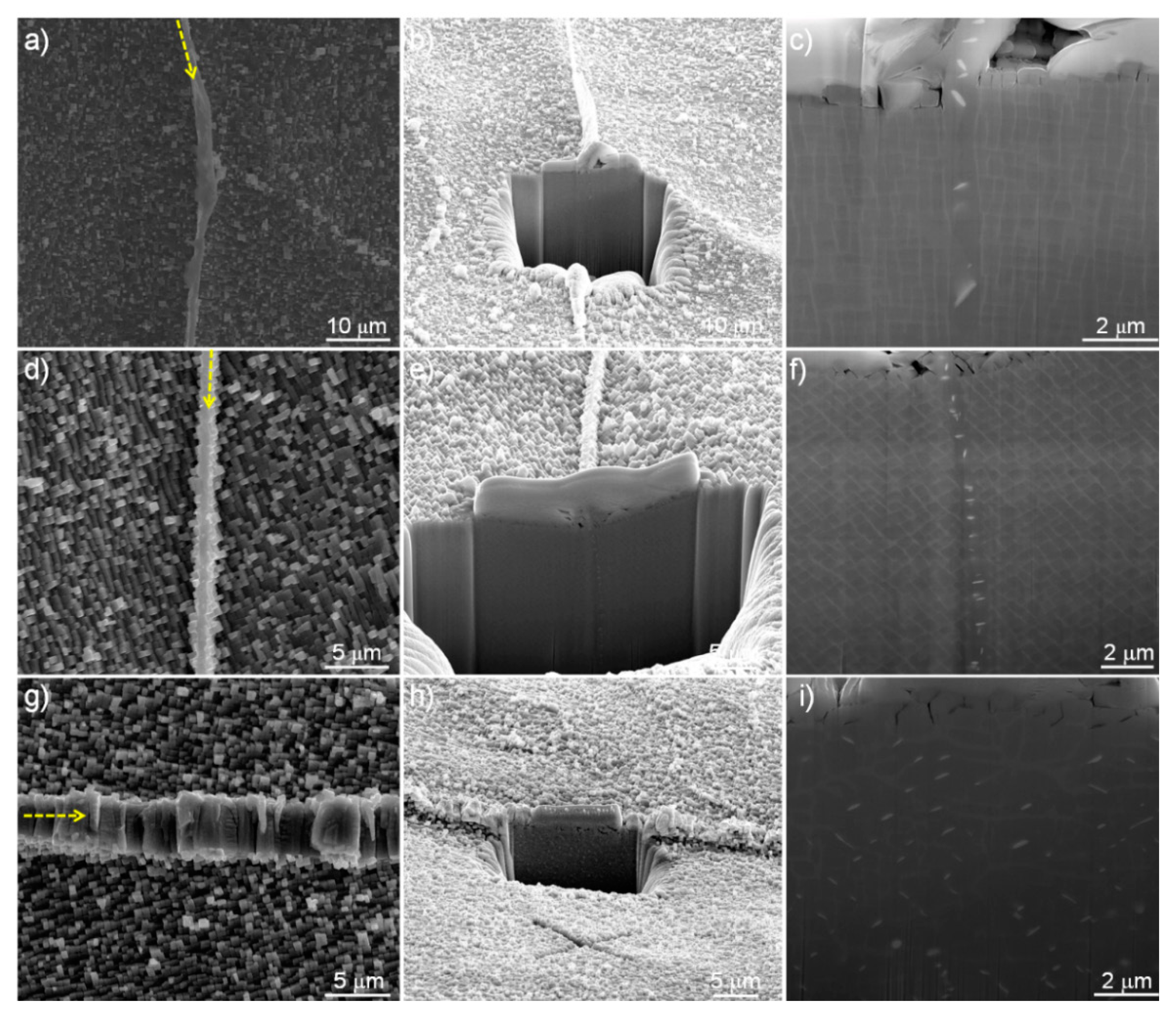
26], a low-angle grain boundary of 7.1°, which was measured by a reflected Laue X-ray system, was selected and observed in order to investigate the formation mechanism of the particles. Clearly, there is a thin intermediate layer in the grain boundary region between a defect grain and the base material (Figure 2a). Then, the region was cross sectioned by a FIB milling technique after depositing a protective platinum layer on a selected area (Figure 2b). This figure also confirms that there is an intermediate layer which was slightly protruded from the surface. A magnified image of the cross section (Figure 2c) shows that there are several fine particles along the boundary regions of two grains which look like the same orientation of {001} of the γ phase (exactly the misorientation of 7.1°). This observation is in good agreement with a previous study which showed a similar microstructure of the particles in a low-angle grain boundary of 6.1° [16].
Then, as a misorientation of over 10° is essential for the discontinuous precipitation [21,22,23,24,25,26], another grain boundary with a misorientation of just 10.2° was also selected and observed. Similar microstructures of the thin intermediate layer (Figure 2d) and fine particles along the boundary (Figure 2e,f) were observed. However, compared with the microstructure with a misorientation of 7.1°, there are greater amounts of the particles in the boundary with a higher misorientation angle. This result means that the fine particles clearly form even in the low-angle boundary, which can form between a defect grain and the base material. Then, for reference, a new turbine blade with a high-angle boundary with a misorientation of 16.5° was observed. As already shown in previous studies [16,17], at the high-angle grain boundary, the intermediate layer becomes wider and clearer (Figure 2g) and most of all, the fine particles are easily recognized along the coherent interface. It should be noted that for more clear visualization of the distribution of the particles, a cross section was made along the intermediate layer, as shown in Figure 2h, which is different from the directions in Figure 2b,e. It is clear that there are a number of fine particles (Figure 2i) within the layer.
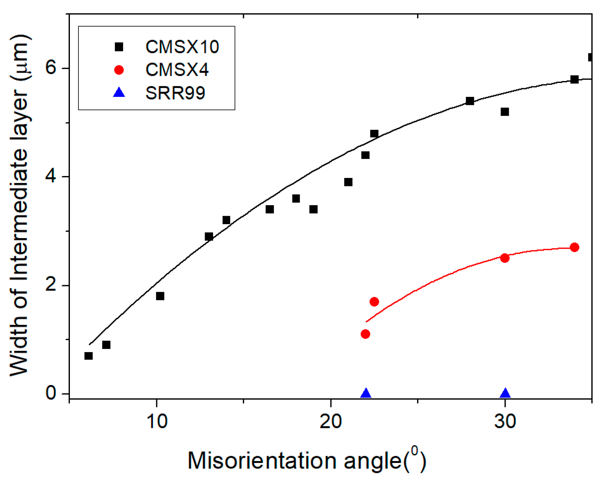
Figure 2 also shows that as the misorientation angle increases, it seems that the intermediate layer becomes thicker. For further investigation into the effect of the misorientation angle on the formation of the intermediate layer, a number of turbine blades containing a high- or low-angle grain boundary were cross sectioned by FIB and then, the misorientation and the width of the intermediate layer were measured by a reflected Laue X-ray system and the {001} orientations of γ in neighbouring two grains. Figure 3 shows the width change of intermediate layers over the misorientation angles. It should be mentioned that for a reference, several other turbine blades made from other raw materials with less or no rhenium content, such as CMSX-4 with 3 wt% rhenium or SRR99 containing no rhenium, were also measured and displayed in the figure, even though the images were not shown here (the general images and cross-sections of CMSX-4 and SRR99 are found in Reference [17]). It is clear that as the misorientation angle increases, the intermediate layer becomes wide even though there is some deviation. It should be also mentioned that the aforementioned fine particles were observed at every boundary in CMSX-10 samples containing 6 wt% rhenium, proving that a number of fine particles may form along the boundary region regardless of the misorientation angle in CMSX-10 turbine blades. For other turbine blades containing lower amounts of rhenium, the width becomes narrow in CMSX-4 samples containing 3 wt% rhenium even at high-angle boundaries. However, some fine particles were detected along the boundaries in CMSX-4. It is worth mentioning that there was no particle or intermediate layer even in a high-angle grain boundary of the SRR-99 sample containing no rhenium. These results suggest that the formation of the intermediate layer and the fine particles is probably related to rhenium in turbine blades. At this point, it is necessary to restate that the particles are also detected in other defect grain boundaries, such as stray, freckle chain and equax grains [16,17,27,28]. Therefore, this result suggests that if there is a boundary region which is formed by a defect grain and the base material, fine particles can be detected.
After observing the cross section, a TEM sample was taken exactly from the region as shown in Figure 2i in order to analyse the fine particles. 
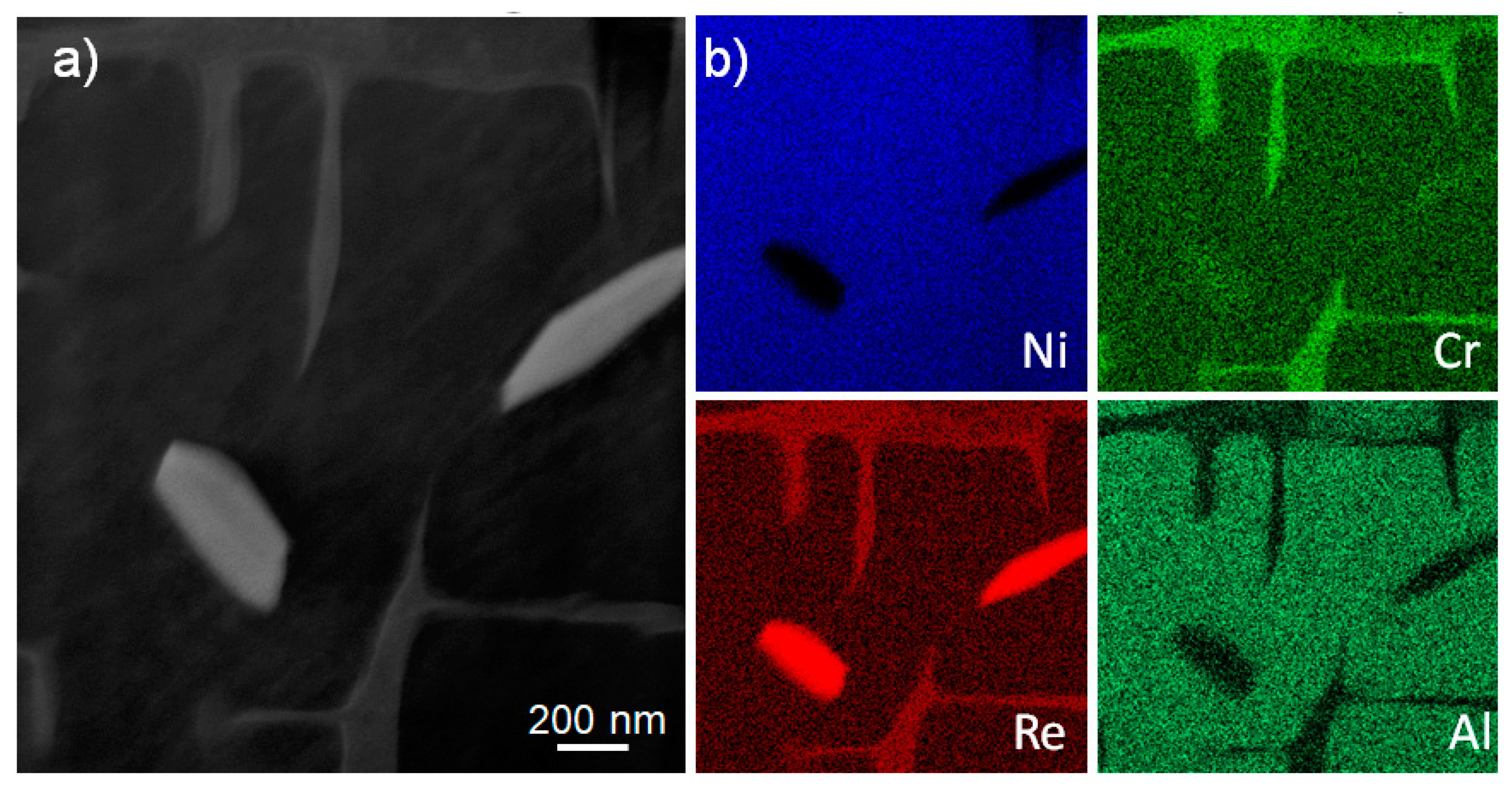
Figure 4 shows STEM images and STEM-EDX element maps near two bright particles. It is worth mentioning that the γ phase is not continuous near the region where two bright particles were formed. Element maps in Figure 4b clearly show the low contrast of nickel and aluminium, slightly bright contrast of chromium, and high contrast of rhenium on the two particles. Most of all, the rhenium contrast is much higher than that on the γ phase. The composition of the particles, which was acquired by STEM-EDX point analysis, is summarized in Table 1. Clearly, the bright particles are rhenium-rich, and therefore, they are called rhenium-rich particles. In Figure 4, as the rhenium-rich particles were formed, the γ-forming elements, such as rhenium and chromium, become depleted and dissolve, and as a result, the rhenium-rich particles are surrounded with the γ phase.
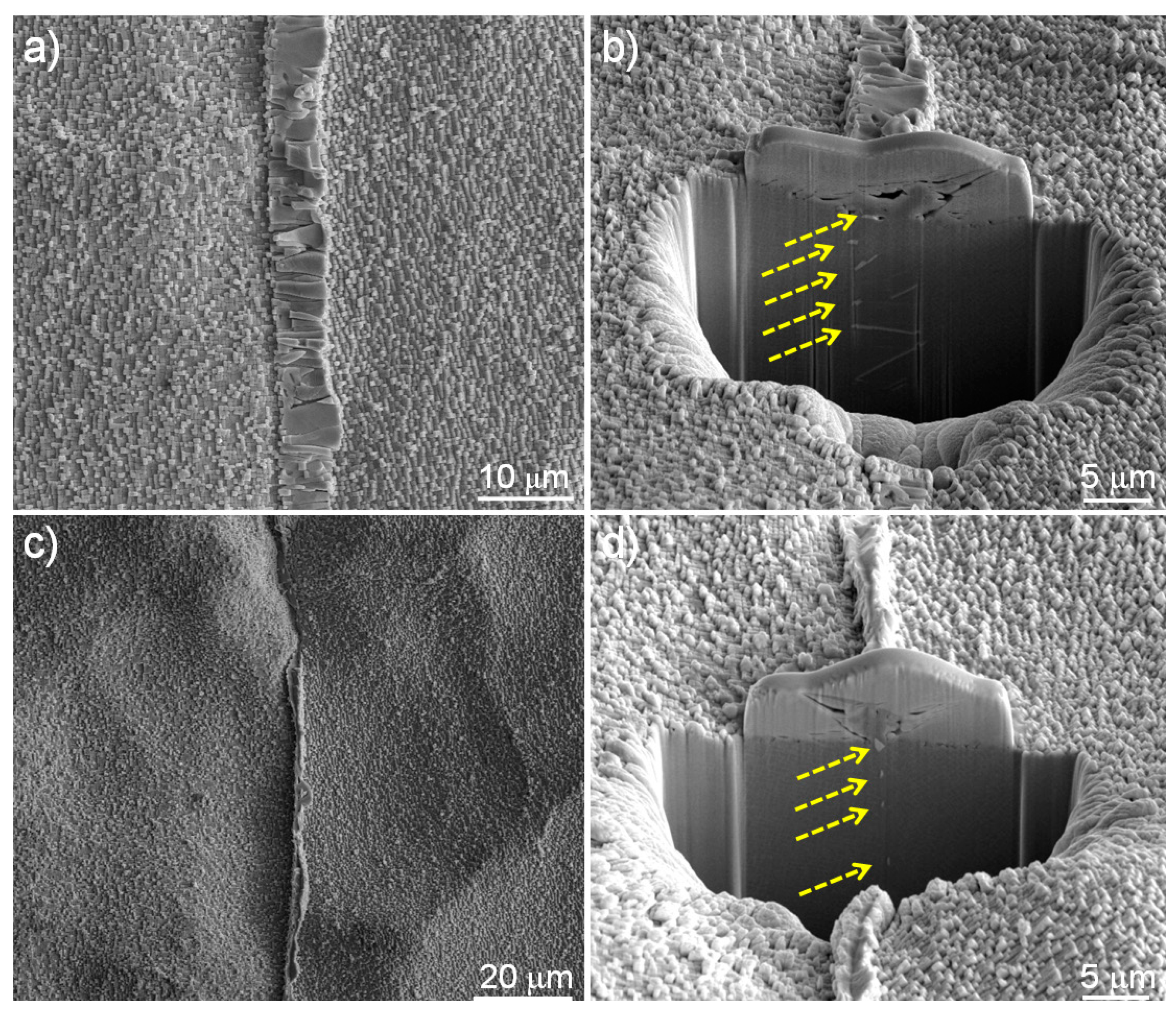
Based on the observations, it is clear that rhenium-rich particles can be detected just along grain boundaries, which can tie up rhenium atoms which were diffused in from two neighbouring grains (a defect grain and a matrix grain). It should be noted that every grain boundary has a misorientation angle. For further investigation of the effect of misorientation angles, a specific turbine blade containing a boundary changing the misorientation angle was selected and observed. A reflected Laue X-ray system showed that the angle was gradually changed from 12° near the edge of the platform to almost zero near the inside. Then, the boundary region was cut out and observed by electron microscopy. The boundary is easily recognised due to the different orientation of γ (001) planes and morphology as marked with an arrow in Figure 5a. Along the boundary line, several cross sections were serially fabricated by FIB milling and after that, the existence of fine particles was confirmed, which means that the boundary region with a misorientation of 12° contained the fine particles (Figure 5b). Then, the serial milling process was continuously performed along the boundary until reaching the region with an almost zero misorientation angle. It should be noted that the images in Figure 5c were acquired near the boundary region with almost zero misorientation angle. Considering the {001} orientations of γ in the neighbouring two grains, their misorientation angle is lower than just a few degrees. Near the central region in Figure 5a, the cross section (Figure 5b) clearly shows the existence of fine particles only along the boundary region although it is really hard to distinguish the boundary without the existence of some blocky γ phases. On the contrary, there are not any fine particles near the zero-boundary region, as shown in Figure 5c. In addition, it is almost impossible to recognise any boundary line in the cross section. These observation results support that grain boundaries can tie up rhenium atoms diffused in from two neighbouring grains and induce the formation of fine particles. If there is not any boundary, rhenium atoms in the left grain (or vice versa) with a driving force at a high enough temperature can be diffused further into the right grain beyond the boundary without piling up at the grain boundaries like the diffusion inside the matrix grain.
Rhenium-rich particles are always detected along the boundary made by a defect grain and the base material. The rhenium-rich particles are formed by the diffusion of rhenium atoms from the dendrite core into the interdendritic region during heat treatment or even during casting, which will be discussed later. When they diffuse, if there is any obstacle or high-energy part, such as a grain boundary in this study, they can be piled up and finally form rhenium-rich particles [27]. However, considering the dendritic microstructure, rhenium atoms can diffuse every direction along the γ phase at high temperatures. In addition, the surface of as-cast or as-heat-treated blades are covered with aluminium oxide, which was formed by the interaction of the mould and the base materials and could block further diffusion of rhenium atoms. Therefore, there is a possibility of the formation of the particles near the top surface of the turbine blades as well as grain boundaries. However, it should be noted that the previous figures were acquired after an etching process, which means that the turbine blades were removed from the manufacturing runner system and etched to expose any defect grains which might be present, because the etchant attacks preferentially into the boundary region. This etching process removes the top surface of turbine blades and reveals the inside microstructure, including the boundary. Therefore, it is necessary to observe the surface of turbine blades without any etching process, or any surface region survived from the etching. 
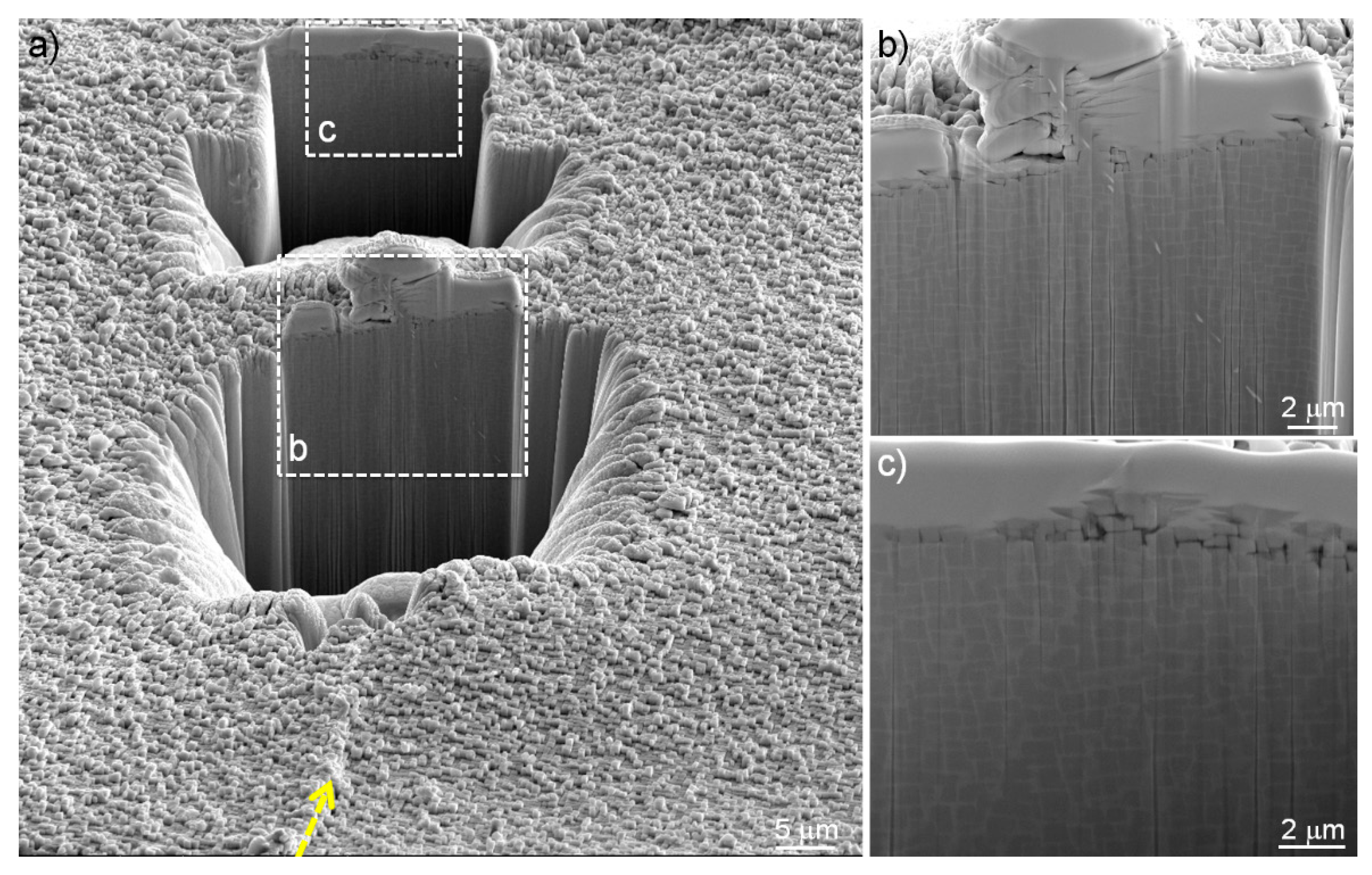
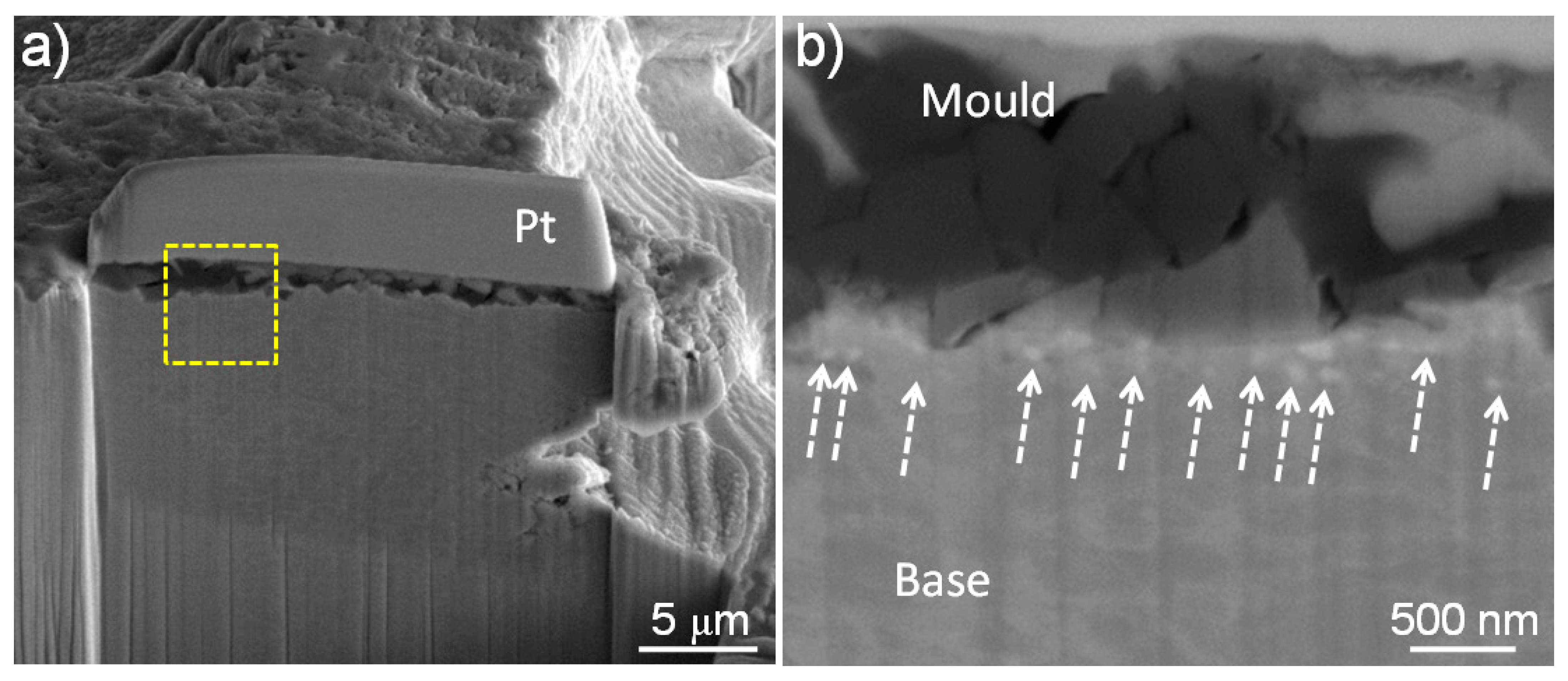
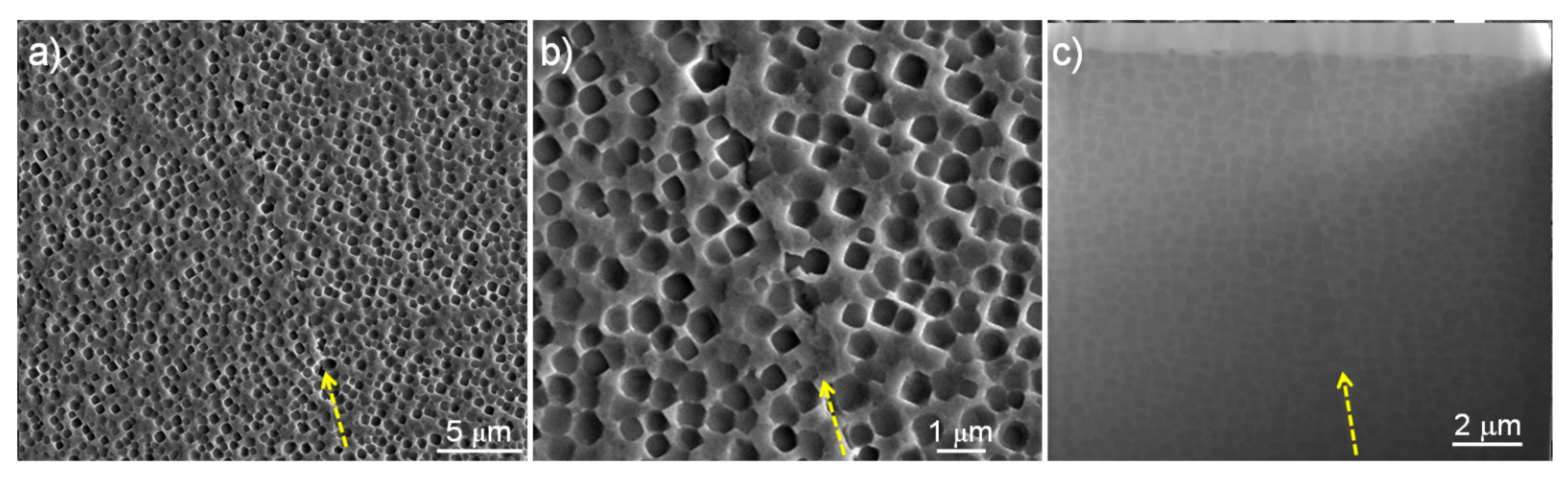
Figure 6 shows SEM images of the top surface of a turbine blade. Accidentally, the mould wall material remained after knocking out the mould and the top surface of the turbine blade component was preserved even after the etching process. The detailed observation of the top surface is described elsewhere [29]. After a protective platinum layer was deposited on the central region, it was cross sectioned by FIB (Figure 6a). It is clear that there are a number of fine rhenium-rich particles which were marked with arrows on the top surface of the base material (Figure 6b). Therefore, this observation suggests that rhenium-rich particles can form not only near grain boundaries but also near the top surface of every single turbine blade.

3.2. Comparison of Rhenium-Rich Particles with Other Particles Detected in the Same Raw Material

One of the most common particles or plates detected in nickel-based single crystal turbine blades manufactured with the same process and raw materials is topologically close packed (TCP) phases [30,31,32,33,34,35,36,37]. 
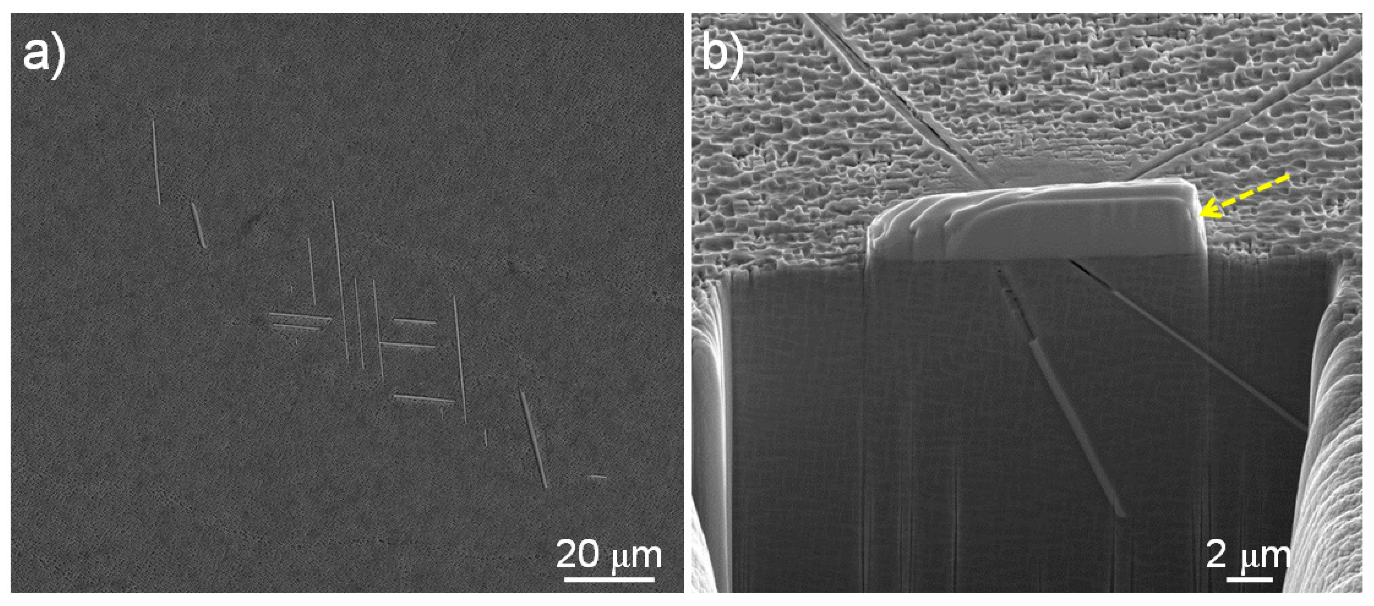
Figure 7 shows the typical morphology of TCP phases. On the polished and etched surface, the TCP phases appear as needles when viewed in the shown orientation. Compared with the rhenium-rich particles with a size of below just 1 µm, the length of TCP phases is usually much longer. In addition, even though the TCP phases look like needles, they are actually plates, as shown in Figure 7b. Most of all, TCP phases are usually formed in the dendrite core, which contains large amounts of refractory elements, while rhenium-rich particles are formed in just any boundary region which is made by a defect grain and the base material, and consequently, probably contains a lower amount of the elements. As a result, their compositions acquired by STEM-EDX point analysis are completely different, as shown in Table 1. The TCP phases contain large amounts of refractory elements, such as tungsten and rhenium, while the rhenium-rich particles are mainly composed of rhenium and nickel. Therefore, these different sizes, morphologies and compositions indicate that the rhenium-rich particles and TCP phases are clearly different.
One previous study showed that there was a possibility to form a similar particle at the boundary region of a recrystallized grain and the base material [16]. Therefore, it is necessary to compare the two particles even though they were formed in different boundary regions, respectively. 
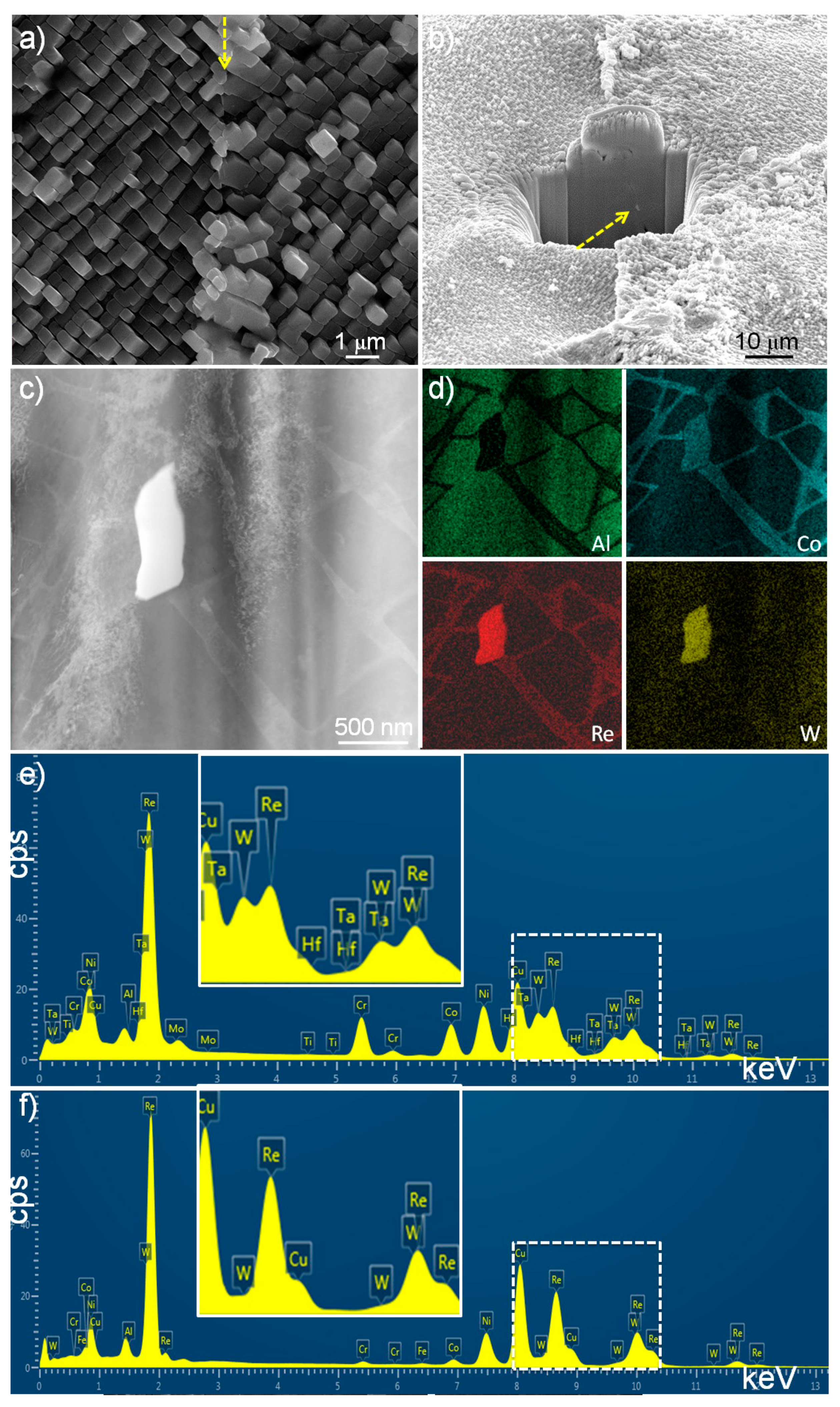
Figure 8a shows the boundary region (marked with an arrow) of a recrystallized grain and a matrix grain, which can be easily recognised due to the different {001} orientations of γ in neighbouring two grains. Compared with the intermediate layer containing rhenium-rich particles, there is not any notable intermediate layer, even though the bright region near the boundary line looked slightly elongated, or an extremely thin layer, which is also shown in a previous study [16]. The cross section of the layer clearly confirms this fact, as well as no rhenium-rich particles (Figure 8b). However, there is only one fine particle deep inside the surface, as marked with an arrow. After the detection of the particle, the region was further fabricated into a TEM sample by FIB.
Figure 8c shows an STEM-HAADF image of the fine particle, which means that the particle was fabricated into a TEM sample without any critical damage during TEM sampling even though it existed deep inside. However, as the region was not uniformly thinned due to the depth, it shows a curtaining effect on the thin lamellae, and most of all, the region was quite thick. Figure 8d shows STEM-EDX element maps near the particle. Even though the image quality in Figure 8c was not great, the maps of aluminium and cobalt show that the γ and γ phases in the upper-left part are not continuous into the bottom right one, which means that there is a boundary region or line between the two regions. In addition, it confirms that the particle exists at the interface. It should be emphasized that there are high contrasts of tungsten as well as rhenium in the particles. In order to confirm the existence of tungsten in the particle, STEM-EDX point analysis was carried out on the particle and clearly displays the peaks corresponding to tungsten (Figure 8e). For reference, an STEM-EDX spectrum which was acquired on a rhenium-rich particle is also shown in Figure 8f. Comparing the two spectra, the particle existed at the boundary of a recrystallized grain, and a matrix grain contains large amounts of tungsten, chromium, and cobalt, while the rhenium-rich particle contains just little amounts of them, which means that the compositions of the two particles are completely different. In addition, the recrystallized grain was formed by strain relaxation through recrystallisation, which was induced by extensive plastic deformation during manufacturing turbine blades and subsequent heat treatments. On the contrary, the rhenium-rich particles in the grain boundaries were formed by the diffusion of refractory elements, such as rhenium, during heat treatment or even during casting. Therefore, particles in the recrystallized boundary can rarely be formed, while a number of rhenium-rich particles can be formed at the boundary region of the defect grains which is formed during casting of the base material.

3.3. Dissolution of Rhenium-Rich Particles

Based on the current study as well as previous studies, it is clear that rhenium-rich particles can be always formed in any grain boundary, regardless of the misorientation angle, and induce the inhomogeneous distribution of alloying elements, especially rhenium, and the change in the microstructure in the surrounding area. Therefore, it is necessary to investigate the possibility of the removal of the rhenium-rich particles. As a previous study showed that an additional heat treatment could dissolve TCP phases [
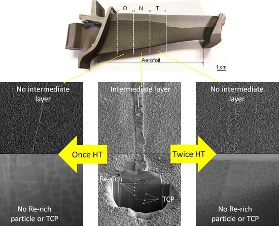
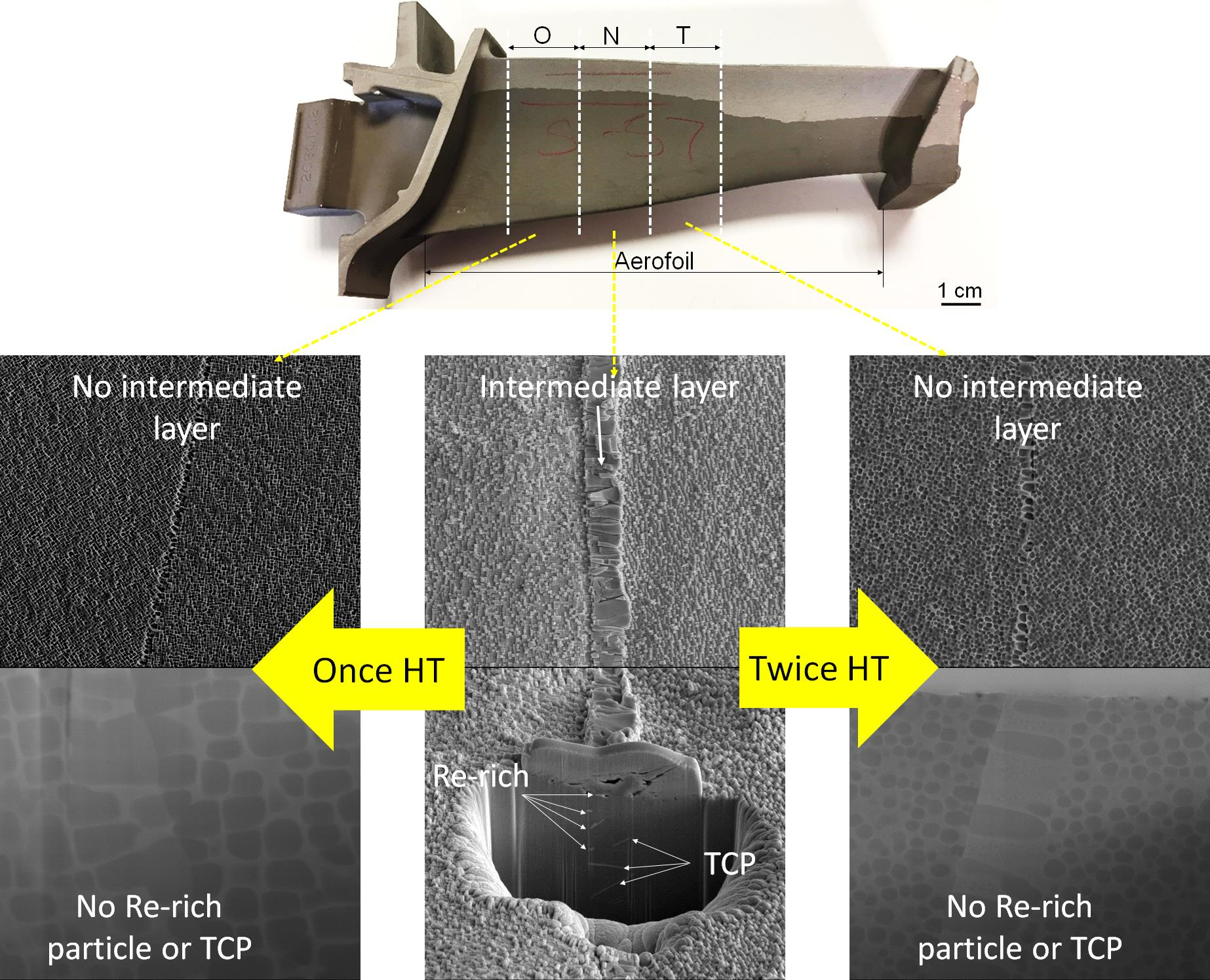
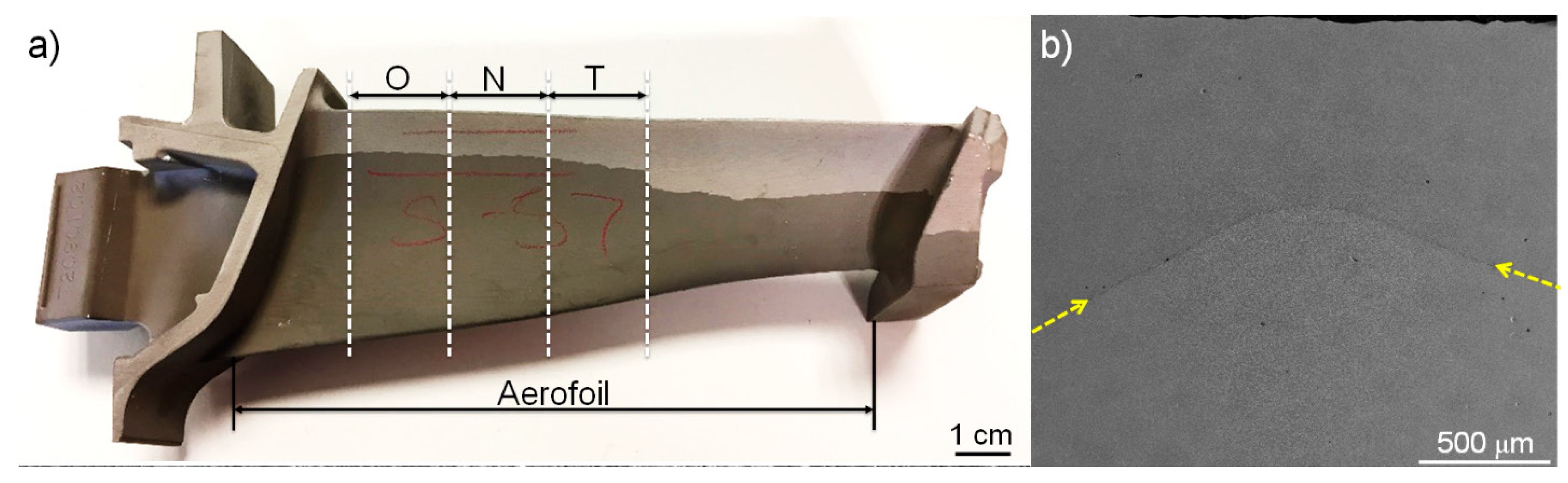
38], a turbine blade containing a grain boundary was additionally heat-treated in order to investigate whether an additional heat treatment could also dissolve the rhenium-rich particles. A turbine blade with a long defect grain boundary was selected, as already shown in Figure 1a, and then heat-treated after the aerofoil part was divided into three regions, i.e., ‘N’ means no additional heat treatment, ‘O’ one additional heat treatment, and ‘T’ twice heat treatment. First of all, without a further heat treatment process, the region marked as ‘N’ was observed to confirm the existence of rhenium-rich particles. Even though the region was vast, using SEM, it was carefully scanned, and it was found that there were two representative regions. First of all, as shown in Figure 9a,b, there is a clear and wide intermediate layer containing rhenium-rich particles as well as some TCP plates. Further to this, there is another region showing a relatively narrow intermediate layer (Figure 9c,d). However, it should be emphasized that regardless of the regions, there were a number of rhenium-rich particles along the boundary region.
Then, the region marked as ‘O’ in Figure 1a was additionally heat-treated. Figure 10a shows that the boundary region is easily recognized by a different morphology. It should be emphasized that even though a higher magnification image (Figure 10b) confirms that the {001} orientations of γ in the neighbouring two grains indicate that there is a boundary region, there is not any notable intermediate layer. The cross section of the boundary region (Figure 10c) clearly shows that there is no intermediate layer even though there are some slightly elongated γ. Most of all, no rhenium-rich particle was found. This observation of no intermediate layer or rhenium-rich particle was confirmed in several other regions. Then, a region that looked like an intermediate layer was selected as shown in Figure 10d. Compared with the other clear and wide intermediate layer, as shown in Figure 9a, the length is much shorter. In addition, even though it looked like a layer at a low magnification observation, a high magnification image (Figure 10b) clearly shows that the layer is extremely thin, or not a layer. In other words, the layer is just composed of some slightly elongated γ. The cross section made exactly from the central region in Figure 10e confirms this. Most of all, as already observed in Figure 10c, there are not any rhenium-rich particles. Therefore, it should be emphasized that the {001} orientations of γ of the neighbouring two grains (a defect grain and a matrix grain) indicate that they make a high angle grain boundary, but there are no rhenium-rich particles along the boundary, except some slightly elongated γ. The observation result means that rhenium-rich particles in grain boundaries can be completely dissolved by an additional heat treatment.
As the formation of rhenium-rich particles is related to the diffusion of refractory elements, there is a possibility that another additional heat treatment may stimulate the diffusion, and consequently, rhenium-rich particles may be re-formed. Therefore, the part marked as ‘T’ in Figure 1a was further heat treated. In other words, that part was twice further heat treated. Figure 11 clearly shows no further precipitation of rhenium-rich particles. Even though it seems that there is a grain boundary region or line, there is not any intermediate layer after scanning the whole boundary region (Figure 11a,b). The cross section (Figure 11c) clearly shows no rhenium-rich particles. This result indicates that any further heat treatment after the complete dissolution of rhenium-rich particles does not induce re-formation of the particles because the driving force for the formation is already diminished, and most of all, uniform distribution of refractory elements, such as rhenium, is achieved through the whole turbine blade.
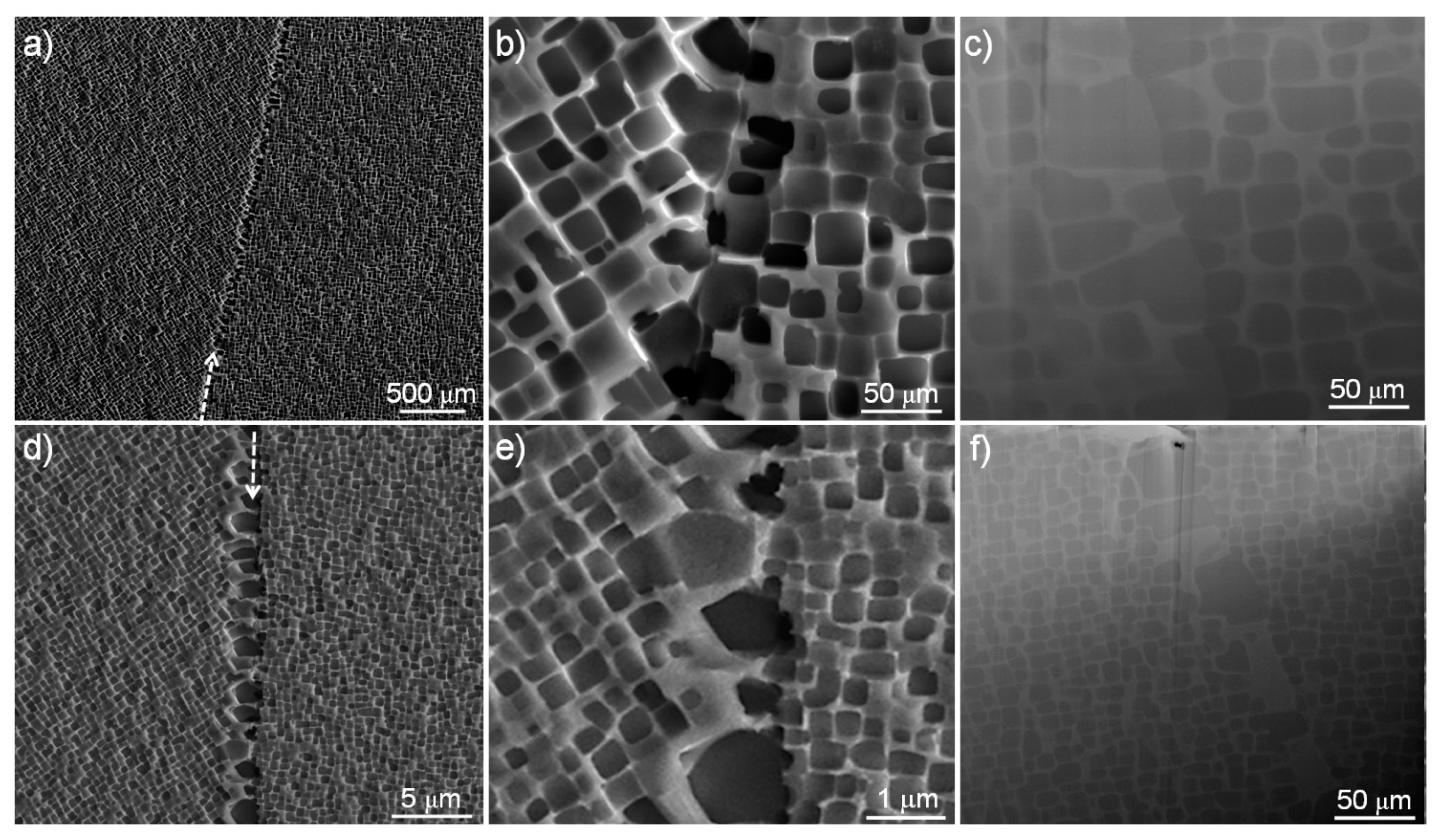
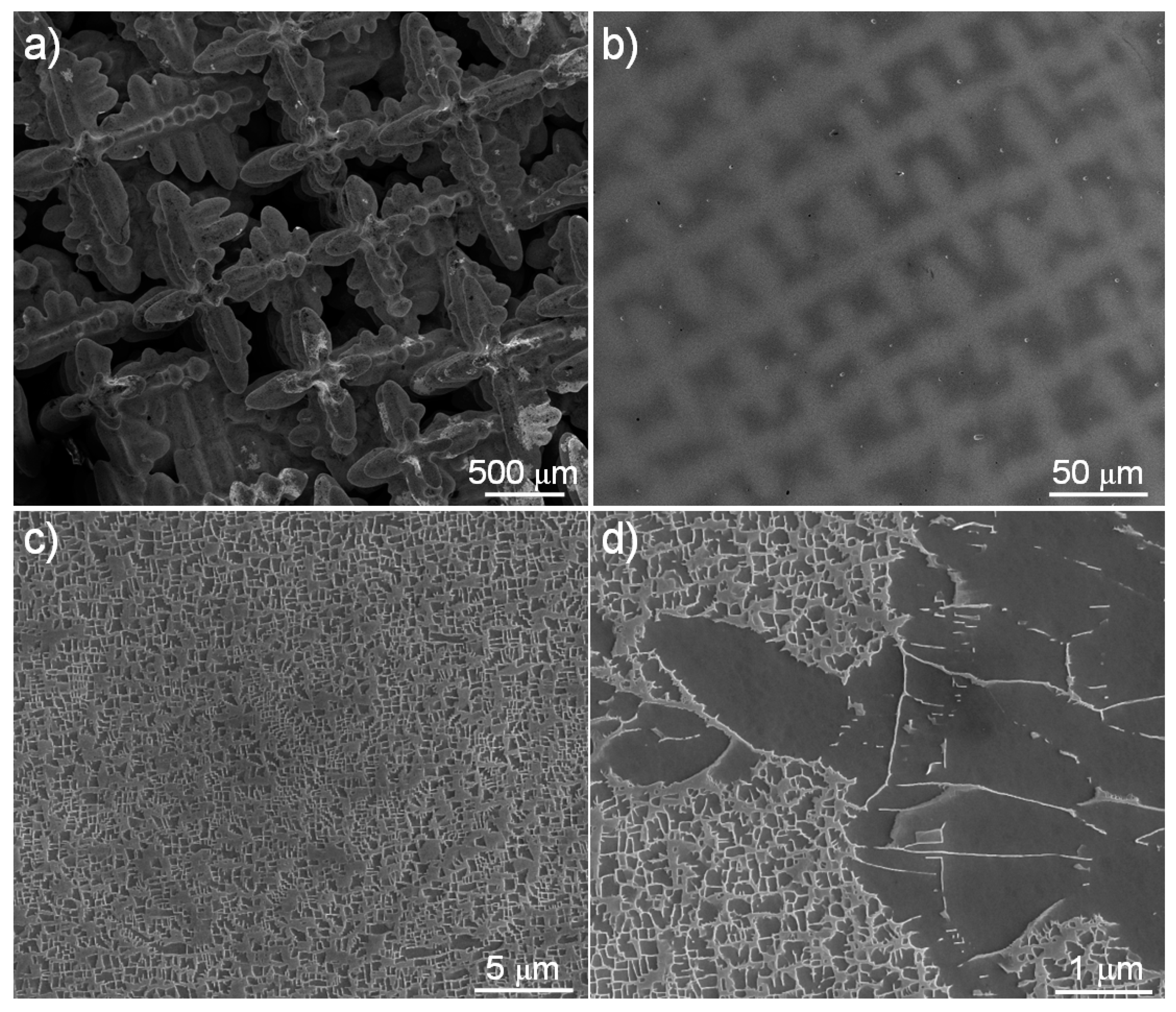
This dissolution mechanism can be supported by the observation of as-cast samples. Figure 12 shows SEM images of as-cast turbine blades. At the uppermost part of the blade, a complete morphology of dendrites is seen (Figure 12a). Then, the sample was mounted, polished and etched to observe the cross section of dendrites (Figure 12b). The dendrite core and the interdendrite region are easily recognized due to the different contrast. Then, the two regions, respectively, were observed at the same magnification (x10,000). It should be emphasized that the dendrite core (Figure 12c) is almost uniformly composed of γ and γ, while the interdendrite region (Figure 12d) is mainly composed of γ with some γ, which means that the volume fraction of γ is much higher than that of γ in the interdendritic region. As already shown in Table 1, alloying elements show different partitioning behaviours. Chromium, cobalt, tungsten and rhenium are mainly partitioned into γ, while aluminium and tantalum are partitioned into γ. At this point, it is necessary to mention that the compositions of γ (or γ) in the core and in the interdendritic region were almost the same regardless of the regions, even though this result is not shown here. Therefore, considering the volume fraction of γ in the interdendritic region, the amounts of chromium, cobalt, tungsten and rhenium in the dendrite core are much higher than those in the interdendritic region. When the γ is dissolved during subsequent heat treatment, they can diffuse from the core into the interdendritic region. Then, finally, γ is uniformly precipitated during heat treatment. However, if there is any obstacle for the diffusion, such as grain boundaries, the diffusion is blocked or slowed down, and finally, rhenium atoms, which have the slowest diffusion coefficient of the alloying elements, are piled up at the boundary and forms rhenium-rich particles. When these rhenium-rich particles are precipitated, as shown in Figure 4, the elements forming the particles are depleted in the surrounding area. Therefore, γ with lower amounts of the particle-forming elements is formed and elongated until it meets the region with the normal amounts of them, which is the intermediate layer.
However, it is necessary to restate that there are two types of intermediate layers along the same grain boundary (Figure 9). This can be explained as the following. As shown in Figure 12, one turbine blade is composed of a number of dendrites with a size of about 500 µm. The dendrite core contains large amounts of chromium, cobalt, tungsten and rhenium. Along a long grain boundary, some regions are close to the dendrite core while some parts are close to the interdendritic region. Therefore, depending on the closure, more amounts of chromium, cobalt, tungsten and rhenium can be piled up in the grain boundary near the dendrite core. As a result, rhenium-rich particles as well as some TCP phases can be formed with a wide intermediate layer as shown in Figure 9b. On the contrary, some parts close to the interdendritic region contain lower amounts of them and consequently, a shorter intermediate layer is formed, as shown in Figure 9d. After that, regardless of the types or regions, i.e., the wide or narrow intermediate layer, most of the layer is dissolved during the additional heat treatment and forms a normal microstructure composed of γ and γ when rhenium-rich particles are dissolved.

4. Summary and Conclusions

Rhenium-rich particles were detected in the boundary regions between a matrix grain and a defect grain in a number of nickel-based single-crystal superalloy turbine blades. From a low-angle grain boundary to a high-angle grain boundary, many fine rhenium-rich particles as well as an intermediate layer were detected along the boundary. As the misorientation angle increased, the number of the particles and the width of the layer increased. The morphology and composition of the particles were different from TCP phases, or a fine rhenium and tungsten-rich particle formed between a recrystallized grain and a matrix grain because the rhenium-rich particles were formed by the diffusion of alloying elements during heat treatment or even during casting, while it is likely that the rhenium- and tungsten-rich particles were formed by the strain relaxation through the recrystallisation. In addition, TCP phases were plates formed near the dendrite core, while the rhenium-rich particles were much smaller and always formed in, if present, any grain boundary region. Additional heat treatment completely dissolved the rhenium-rich particles, even in a high-angle grain boundary. However, after the first additional heat treatment, uniform distribution of alloying elements was achieved, and as a result, there was no further driving force for the diffusion of the alloying elements for the formation of the layer as well as rhenium-rich particles during the second additional heat treatment.
Even though the rhenium-rich particles are formed by the diffusion of alloying elements, especially rhenium, during casting and heat treatment, they are not a main reason for inducing a defect grain, but a side product. It is well known that the secondary defect grain deteriorates the superior properties of the turbine blades. However, if a defect grain forms within a turbine blade, regardless of the size and the misorientation angle, rhenium-rich particles can induce the inhomogeneous distribution of alloying elements, and the formation of an intermediate layer can exist even in a low-angle grain boundary and severely deteriorate the superior properties. Therefore, as shown in this study, the rhenium-rich particles should be completely removed by adjusting the heat treatment process. Finally, the current study suggests that as the amount of rhenium in the commercial turbine blades, which makes up over 60% of the total price of alloying elements, may be over added, there may be a need to investigate the optimum amount of rhenium without the loss of the expensive element induced by the excessive formation of rhenium-rich particles and inhomogeneous microstructures. Further to this, as the surface of turbine blades may also contain rhenium-rich particles, as shown in this study, there may be a requirement to investigate the particles on the surface and their removal simply by an additional heat treatment without any other deterioration of properties.

Author Contributions

Conceptualization, development of the methodology and analysis of the data was performed by K.P.; discussion was performed by K.P. and P.W.; writing and review was performed by K.P. and P.W. All authors have read and agreed to the published version of the manuscript.

Funding

This work was supported by the Engineering and Physical Sciences Research Council, grant number EP/T018518/1.

Institutional Review Board Statement

Not applicable.

Informed Consent Statement

Not applicable.

Data Availability Statement

Not applicable.

Acknowledgments

The financial support and provision of evaluation test pieces by Rolls-Royce plc is acknowledged.

Conflicts of Interest

Not applicable.

References

  1. Durand-Charre, M. The Microstructure of Superalloys; OPA: Amsterdam, The Netherlands, 1997; pp. 1–12. [Google Scholar]
  2. Reed, R.C. The Superalloys: Fundamentals and Applications; Cambridge University Press: Cambridge, UK, 2006; pp. 33–86. [Google Scholar]
  3. Smith, W.F. Structure and Properties of Engineering Alloys, 2nd ed.; McGraw-Hill Book Co.: New York, NY, USA, 1994; pp. 199–209. [Google Scholar]
  4. Geddes, B.; Leon, H.; Huang, X. Superalloys: Alloying and Performance; ASM International: Materials Park, OH, USA, 2010; pp. 1–109. [Google Scholar]
  5. Warren, P.J.; Cerezo, A.; Smith, G.D.W. An atom probe study of the distribution of rhenium in a nickel-based superalloy. Mater. Sci. Eng. A 1998, 250, 88–92. [Google Scholar] [CrossRef]
  6. Giamei, A.F.; Anton, D.L. Rhenium additions to a Ni-base superalloy: Effects on microstructure. Metall. Trans. A 1985, 16, 1997–2005. [Google Scholar] [CrossRef]
  7. Yeh, A.C.; Tin, S. Effects of Ru and Re additions on the high temperature flow stresses of Ni-base single crystal superalloys. Scr. Mater. 2005, 52, 519–524. [Google Scholar] [CrossRef]
  8. Reed, R.C.; Tao, T.; Warnken, N. Alloys-By-Design: Application to nickel-based single crystal superalloys. Acta Mater. 2009, 57, 5898–5913. [Google Scholar] [CrossRef]
  9. Bar-Cohen, Y. High Temperature Materials and Mechanisms; CRC Press: Boca Raton, FL, USA, 2014; pp. 110–117. [Google Scholar]
  10. Napolitano, R.E.; Schaefer, R.J. The convergence-fault mechanism for low-angle boundary formation in single-crystal castings. J. Mater. Sci. 2000, 35, 1641–1659. [Google Scholar] [CrossRef]
  11. Panwisawas, C.; Mathur, H.; Gebelin, J.C.; Putman, D.; Rae, C.M.F.; Reed, R.C. Prediction of recrystallization in investment cast single-crystal superalloys. Acta Mater. 2013, 61, 51–66. [Google Scholar] [CrossRef]
  12. Mathur, H.N.; Panwisawas, C.; Jones, C.N.; Reed, R.C.; Rae, C.M.F. Nucleation of recrystallisation in castings of single crystal Ni-based superalloys. Acta Mater. 2017, 129, 112–123. [Google Scholar] [CrossRef]
  13. Brewster, G.; Dong, H.B.; Green, N.R.; D’Souza, N. Surface Segregation during Directional Solidification of Ni-Base Superalloys. Metall. Mater. Trans. B 2008, 39, 87–93. [Google Scholar] [CrossRef]
  14. Brewster, G.; D’Souza, N.; Ryder, K.S.; Simmonds, S.; Dong, H.B. Mechanism for Formation of Surface Scale during Directional Solidification of Ni-Base Superalloys. Metall. Mater. Trans. A 2012, 43, 1288–1302. [Google Scholar] [CrossRef]
  15. Simmonds, S.; Souza, N.D.; Ryder, K.S.; Dong, H. Analysis of surface scale on the Ni-based superalloy CMSX-10N and proposed mechanism of formation. IOP Conf. Ser. Mater. Sci. Eng. 2012, 27, 012038. [Google Scholar] [CrossRef]
  16. Kim, K.; Withey, P. Detection of Rhenium-Rich Particles at Grain Boundaries in Nickel-Base Superalloy Turbine Blades. Mater. Trans. 2016, 57, 1698–1706. [Google Scholar] [CrossRef]
  17. Kim, K.; Withey, P. Formation of an Intermediate Layer between Grains in Nickel-Based Superalloy Turbine Blades. Metall. Mater. Trans. A 2017, 48, 2932–2942. [Google Scholar] [CrossRef]
  18. Kim, K.; Withey, P.; Griffiths, W.D. Detection of an Intermediate Layer Containing a Rhenium-Rich Particle at Grain Boundaries Formed within Single Crystal Nickel-Based Superalloys. Metall. Mater. Trans. A 2015, 46, 1024–1029. [Google Scholar] [CrossRef]
  19. Kim, K.; Watanabe, M.; Kawakita, J.; Kuroda, S. Grain refinement in a single titanium powder particle impacted at high velocity. Scr. Mater. 2008, 59, 768–771. [Google Scholar] [CrossRef]
  20. Kim, K. Formation of Fine Clusters in High-Temperature Oxidation of Molten Aluminum. Metall. Mater. Trans. A 2014, 45, 3650–3660. [Google Scholar] [CrossRef]
  21. JEOL-Energy Table for EDS Analysis. Available online: www.jeol.com (accessed on 28 September 2013).
  22. Scarlin, R.B. Discontinuous precipitation in a directionally-solidified nickel-base alloy. Scr. Metall. 1976, 10, 711–715. [Google Scholar] [CrossRef]
  23. Manna, I.; Pabi, S.K.; Gust, W. Discontinuous reactions in solids. Int. Mater. Rev. 2001, 46, 53–91. [Google Scholar] [CrossRef]
  24. Nystrom, J.D.; Pollock, T.M.; Murphy, W.H.; Garg, A. Discontinuous cellular precipitation in a high-refractory nickel-base superalloy. Metall. Mater. Trans. A 1997, 28, 2443–2452. [Google Scholar] [CrossRef]
  25. Brener, E.A.; Temkin, D.E. Theory of discontinuous precipitation: Importance of the elastic strain. Acta Mater. 2003, 51, 797–803. [Google Scholar] [CrossRef]
  26. Heckl, A.; Cenanovic, S.; Goken, M.; Singer, R.F. Discontinuous Precipitation and Phase Stability In Re- and Ru-Containing Nickel-Base Superalloys. Metall. Mater. Trans. A 2012, 43, 10–19. [Google Scholar] [CrossRef]
  27. Welton, D.; D’Souza, N.; Kelleher, J.; Gardner, S.; Dong, Z.H.; West, G.D.; Dong, H. Discontinuous Precipitation in Ni-Base Superalloys During Solution Heat Treatment. Metall. Mater. Trans. A 2015, 46, 4298–4315. [Google Scholar] [CrossRef]
  28. Park, K.; Withey, P. Formation of Secondary Phases in the Boundary between Surface Defect Grains and Matrix in Third Generation Nickel-Based Single Crystal Superalloy Turbine Blades. In Thermec 2018: 10th International Conference on Processing and Manufacturing of Advanced Materials; Shabadi, R., Ionescu, M., Jeandin, M., Richard, C., Chandra, T., Eds.; 2018; Volume 941, pp. 766–771. [Google Scholar]
  29. Park, K.; Paul, W. Formation and prevention of a surface defect on the aerofoil of as-cast nickel-based single crystal turbine blades. Adv. Eng. Mater. 2021, in press. [Google Scholar] [CrossRef]
  30. Seiser, B.; Drautz, R.; Pettifor, D.G. TCP phase predictions in Ni-based superalloys: Structure maps revisited. Acta Mater. 2011, 59, 749–763. [Google Scholar] [CrossRef]
  31. Matuszewski, K.; Rettig, R.; Matysiak, H.; Peng, Z.; Povstugar, I.; Choi, P.; Müller, J.; Raabe, D.; Spiecker, E.; Kurzydłowski, K.J.; et al. Effect of ruthenium on the precipitation of topologically close packed phases in Ni-based superalloys of 3rd and 4th generation. Acta Mater. 2015, 95, 274–283. [Google Scholar] [CrossRef]
  32. Tan, X.P.; Hong, H.U.; Choi, B.G.; Kim, I.S.; Jo, C.Y.; Jin, T.; Hu, Z.Q. Characterization of topologically close-packed phases in secondary reaction zone in a coated CMSX-4 single crystal Ni-based superalloy. J. Mater. Sci. 2013, 48, 1085–1089. [Google Scholar] [CrossRef]
  33. Tin, S.; Pollock, T.M. Phase instabilities and carbon additions in single-crystal nickel-base superalloys. Mater. Sci. Eng. A 2003, 348, 111–121. [Google Scholar] [CrossRef]
  34. Volek, A.; Singer, R.F.; Buergel, R.; Grossmann, J.; Wang, Y. Influence of topologically closed packed phase formation on creep rupture life of directionally solidified nickel-base superalloys. Metall. Mater. Trans. A 2006, 37, 405–410. [Google Scholar] [CrossRef]
  35. Rae, C.M.F.; Hook, M.S.; Reed, R.C. The effect of TCP morphology on the development of aluminide coated superalloys. Mater. Sci. Eng. A 2005, 396, 231–239. [Google Scholar] [CrossRef]
  36. Gao, S.; Zhou, Y.Z.; Li, C.F.; Cui, J.P.; Liu, Z.Q.; Jin, T. In situ investigation on the precipitation of topologically close-packed phase in Ni-base single crystal superalloy. J. Alloys Compd 2014, 610, 589–593. [Google Scholar] [CrossRef]
  37. Kablov, E.N.; Petrushin, N.V.; Bronfin, M.B.; Alekseev, A.A. Specific features of rhenium-alloyed single-crystal nickel superalloys. Russian Metall. 2006, 2006, 406–414. [Google Scholar] [CrossRef]
  38. Park, K.; Withey, P. Observation of the Dissolution of Topologically Close Packed Phases by an Additional Heat Treatment in Third Generation Nickel-Based Single Crystal Superalloy Turbine Blades. Adv. Eng. Mater. 2018, 20, 1700987. [Google Scholar] [CrossRef]
Figure 1. A photo (a) and an SEM image (b) of a selected turbine blade containing a large-scale high-angle grain boundary. Note that the arrows in panel (b) indicate the grain boundary.
Crystals 11 01201 g001
Figure 2. General images of intermediate layers containing rhenium-rich particles observed at three different turbine blades: (ac) a low-angle (7.1°) grain boundary, (df) another low-angle (10.2°) grain boundary, and (gi) a high-angle (16.5°) grain boundary. Panels (a,d,g) are top views and other panels are tilting views. Note that the arrows in (a,d,g), respectively, indicates an intermediate layer, and the cross-sectioning directions in (b,e,h) are different.
Crystals 11 01201 g002
Figure 3. Width change of intermediate layers over misorientation angles of secondary grains and a matrix grain in CMSX-10 turbine blades containing 6 wt% rhenium, and some other blades with lower (3 wt%, CMSX-4) or no (SRR-99) amounts of rhenium.
Crystals 11 01201 g003
Figure 4. STEM observation and STEM-EDX analysis of rhenium-rich particles detected in Figure 2i: (a) STEM-HAADF image and (b) STEM-EDX element maps of nickel, chromium, rhenium, and aluminium.
Crystals 11 01201 g004
Figure 5. SEM images of a boundary region with changing of misorientation angles: (a) tilting view after cross-sectioning by FIB milling with arrow indicating the boundary line, and (b,c) magnified images at the marked regions in (a), respectively.
Crystals 11 01201 g005
Figure 6. SEM tilting views at a low magnification (a) and a magnified image at the marked region in panel (a,b) of top surface of a turbine blade. Note that the arrows in (b) indicate rhenium-rich particles on the top surface of the base material and the detailed analysis will be published elsewhere.
Crystals 11 01201 g006
Figure 7. SEM images of TCP phases: (a) a general image, and (b) a tilting view of a cross section revealing that TCP phases are plates. Note that the two different types of etchants were used in panels (a,b), respectively. The arrow in (b) indicates a platinum layer.
Crystals 11 01201 g007
Figure 8. SEM and TEM observation and analysis of a fine particle detected in a grain boundary between a recrystallized grain and the base material: (a) a general image of the grain boundary, (b) a tilting view after cross-sectioning of the central region of panel (a), (c,d) a STEM-HAADF image (c) and STEM-EDX element maps of aluminium, cobalt, rhenium, and tungsten (d) near the fine particle detected in (b) after TEM sampling, and (e,f) STEM-EDX point analysis of the fine particle (e) and a reference rhenium-rich particle (f) acquired from the fine particle detected in Figure 4.
Crystals 11 01201 g008
Figure 9. SEM images of a selected turbine blade containing a large-scale high-angle grain boundary in Figure 1a: (a,b) a top view (a) and a tilting view after cross-sectioning (d) of a region containing a wide intermediate layer, and (c,d) a top view (c) and a tilting view (d) of a narrow intermediate layer. The arrows in (b,d) indicate fine rhenium-rich particles or TCP phases.
Crystals 11 01201 g009
Figure 10. SEM images of the part marked as ‘O’ in the turbine blade of Figure 1a after an additional heat treatment at two representative regions, such as a general boundary (ac) and a specific region that looked like a wide boundary (df): (a,d) a general image with an arrow indicating the boundary, (b,e) a magnified image of panels (a,d), respectively, and (c,f) a tilting view after cross sectioning of a general boundary (b) and a specific region (e), respectively.
Crystals 11 01201 g010
Figure 11. SEM images of the part marked as ‘T’ in Figure 1a after twice additional heat treatment: (a) a general image, (b) a magnified image of (a), and (c) a tilting view after cross sectioning of the central region in (b). The arrow in each panel indicates the boundary line.
Crystals 11 01201 g011
Figure 12. SEM images of an as-cast turbine blade: (a) a general image of an as-cast blade, (b) a general image after mounting and polishing and (c,d) magnified images at the dendrite core (c) and at the interdendritic region (d).
Crystals 11 01201 g012
Table 1. Compositions (at pct) of raw material and several phases and particles measured by STEM-EDX [16,17].
ElementRawγγTCPRe-RichRe-W
Al13.66.315.62.42.51.0
Ti0.10.00.10.10.10.0
Cr1.84.11.04.01.715.3
Co3.25.92.76.33.814.2
Nb0.00.00.00.00.00.0
Mo0.30.30.00.63.02.7
Ta3.03.64.65.20.72.6
W1.93.42.416.23.821.3
Re2.45.90.041.061.621.9
NiBal.Bal.Bal.Bal.Bal.Bal.
Publisher’s Note: MDPI stays neutral with regard to jurisdictional claims in published maps and institutional affiliations.

