Article

Effect of Stacking Fault Energy on Microstructure and Texture Evolution during the Rolling of Non-Equiatomic CrMnFeCoNi High-Entropy Alloys

1
Institute of Solid State and Materials Physics, Technische Universität Dresden, 01062 Dresden, Germany
2
Discipline of Mechanical Engineering, Indian Institute of Technology Indore, Indore 453552, India
3
Department of Materials Engineering, Indian Institute of Science Bangalore, Bangalore 560012, India
*
Author to whom correspondence should be addressed.
Crystals 2020, 10(7), 607; https://doi.org/10.3390/cryst10070607
Submission received: 12 June 2020 / Revised: 5 July 2020 / Accepted: 9 July 2020 / Published: 13 July 2020

Abstract

:
The evolution of microstructure and texture in three non-equiatomic CrMnFeCoNi high-entropy alloys (HEAs) with varying stacking fault energy (SFE) has been studied in up to 90% rolling reductions at both room and cryogenic temperature. All the HEAs deform by dislocation slip and additional mechanical twinning at intermediate and shear banding at high rolling strains. The microstructure is quite heterogeneous and, with strain, becomes highly fragmented. During rolling, a characteristic brass-type texture develops. Its strength increases with a decreasing SFE and the lowering of the rolling temperature. The texture evolution is discussed with regard to planar slip, mechanical twinning, and shear banding.

1. Introduction

Since 2004, multicomponent alloys or high-entropy alloys (HEAs) have received much attention among researchers, mainly because of their extraordinary structural properties and potential applications identified in various areas [1,2,3,4,5,6,7,8,9,10,11,12,13,14,15,16]. HEAs are loosely defined as random mixtures of multiple principal elements that lead to a high configurational entropy. They generally consist of five or more elements with an atomic concentration between 5% and 35% [2]. Although there is some controversy around this definition, it is sure that such combinations provide a larger composition space to design new alloys in simple solid solution form. From that point of view, many non-equiatomic HEAs are identified with unique microstructures and desirable properties [17,18,19,20,21,22,23,24,25,26,27,28,29,30]. The most commonly referred to and well-investigated HEA has the equiatomic composition CrMnFeCoNi and is a single-phase solid solution with a face-centered cubic (FCC) structure. This alloy is most popularly known as the Cantor alloy [6,7,8]. It exhibits an outstanding combination of strength and ductility at room temperature (RT, 296 K) and also at cryogenic temperature (Cryo-T, 77 K) [31]. The latter is mainly attributed to mechanical twinning. The twinning-induced plasticity (TWIP) of FCC HEAs is strongly affected by the stacking fault energy (SFE) mainly depending on the individual element concentration. In that respect, many series of non-equiatomic CrMnFeCoNi HEAs with varying elemental concentrations were designed to lower the SFE and, thus, to optimize the mechanical properties [18,19,20,21,22,23,24,25,26,27].
Recently, a comprehensive review has been published by two of the present authors on the deformation and annealing textures of FCC HEAs in relation to their microstructures [32]. The review makes clear that there is still a lack of investigations on the microstructure and texture evolution of non-equiatomic FCC HEAs. Therefore, it was the aim of the present study to investigate the micro-mechanisms of deformation with regard to the texture formation during the rolling of non-equiatomic FCC CrMnFeCoNi HEAs as a function of the SFE, processing temperature, and imposed rolling strains. Three different HEAs with varying SFEs were selected from the existing literature [26,27]; their compositions and SFEs are listed in Table 1. The crucial role of slip, mechanical twinning, and shear banding on texture formation has been investigated, primarily as a function of SFE.

2. Experimental

The chemical composition of the non-equiatomic HEAs investigated is given in Table 1. Button-shaped ingots were produced by arc-melting under vacuum and re-melted several times in order to get a homogeneous mixture of the constituents. After homogenization at 1100 °C for 5 h under an argon atmosphere, the ingots were cold-rolled (CR) to a 50% thickness reduction and annealed at 900 °C for 2 h, yielding a fully recrystallized microstructure. This condition was taken as a starting point (initial) for further unidirectional rolling. Thickness reductions of 40% (true strain = 0.5) and 90% (2.3) at RT and Cryo-T were produced with a laboratory-scale rolling mill (Newfield Engineers Pvt. Ltd., Bangalore, India), roll diameter of 105 mm, and rolling speed of 2 m/min. Plates of 4 mm thickness were CR and Cryo-rolled (Cryo-R) to a 0.4 mm final thickness in steps of ≤ 10% reduction per pass. For Cryo-R, before each pass the sheets were immersed in liquid nitrogen for 15 min.
A microstructural characterization was carried out by scanning electron microscopy (SEM) using a Zeiss Supra 55 microscope (Carl Zeiss AG, Oberkochen, Germany) operated at 20 kV and equipped with an electron backscatter diffraction (EBSD, Nordlys system, Oxford Instruments plc, Abingdon, UK) system. All the samples for the EBSD measurements were mechanically polished, followed by a careful electro-polishing at RT using a mixture of perchloric acid and methanol with a volume ratio of 1:9. EBSD of all the samples was carried out on the rolling plane at mid-thickness. The EBSD scan step sizes were kept between 1 and 0.3 μm for the starting and deformed materials. A lower step size of 30 nm was used for the sheets with a 90% CR reduction. The acquired EBSD data were analyzed using the HKL software version 5.2 (Oxford Instruments, Witney, UK).
The verification of single-phase FCC structure and texture measurements of the CR and Cryo-R samples were made with a HZG-4 X-ray texture goniometer (Seifert FPM, Freiberg, Germany) using Co-Kα radiation. Before the measurement, the HEAs were carefully prepared as described above. Incomplete (111), (200), and (220) pole figures (PFs) were measured on the rolling plane of the sheets at mid-thickness. All the acquired data were corrected for background and defocusing. The orientation distribution function (ODF) was calculated from the measured PFs using the LaboTex V3 software (Labosoft s.c., Krakow, Poland) [34] applying orthorhombic sample symmetry. The Euler angles are given in the Bunge notation [35]. To quantify the strength of texture, the volume fractions of main rolling texture components were calculated using a spread of 15° from their ideal orientation.

3. Results

Figure 1 reveals that the three HEAs used in all the conditions (initial, after CR, and Cryo-R) are single FCC phase materials. Within the resolution of X-ray diffraction, no transformation to hexagonal martensite could be detected after Cryo-R. Such a phase transformation was reported for the Cantor alloy after high-pressure torsion at Cryo-T (e.g., [36]) The starting microstructures of the three HEAs are shown in Figure 2 in the form of inverse pole figure (IPF) maps. All the HEAs (1 to 3) are fully recrystallized and have nearly equiaxed grains with a similar mean size of about 20 µm (twin boundaries (TBs) excluded). Profuse Σ3 annealing TBs are clearly visible in all the three starting microstructures. The initial textures of all the HEAs shown as (111) PFs are quite weak, with intensities smaller than 2 times random. The weakening/randomization of the rolling textures after the recrystallization and grain growth of the FCC HEAs has already been reported in [32]. Thus, this is a very general behavior of these materials and, therefore, a detailed analysis of the recrystallization textures will not be carried out here.
IPF maps of the HEAs after CR and Cryo-R reductions of 40% and 90% are shown in Figure 3. After 40% CR, the microstructures of all the HEAs are characterized by grains elongated in the rolling direction (RD) and large misorientation gradients within the grains, indicating dislocation slip as the main deformation mechanism. In addition, deformation twins are clearly visible. They appear as bundles in the micron range. The thickness of individual twin lamellae in the bundles is in the range of several nanometers. HEA-3 shows the highest fraction of deformation twins. After 90% CR reduction, HEA-1 shows the development of a micro-fragmented lamellar deformation microstructure. The fragmentation is much finer (sub-micron range) in the other two HEAs. Moreover, all the microstructures after the 90% CR reduction contain shear bands. It should be mentioned that the EBSD indexation rate for the 90% CR sheets is only about 50% due to the heavily fragmented microstructure with fine-scale shear bands.
Similar to the CR HEAs, besides dislocation activity, the presence of deformation twins is clearly visible in all the microstructures after the 40% Cryo-R reduction. Compared to the CR, the propensity for twinning is higher during Cryo-R. There exists a larger fraction of deformation twins in HEA-3 compared to the other two. Evidently, by lowering the rolling temperature, the onset of twinning shifts to lower strain values. The backscatter electron (BSE) images (Figure 4) of HEA-3 are provided to further demonstrate the intensive shear banding and concomitant crack formation at RT and Cryo-T.
The φ2 = 0°, 45°, and 65° ODF sections of the three HEAs after different CR and Cryo-R reductions are shown in Figure 5 and Figure 6, respectively. At both rolling temperatures, a typical brass-type rolling texture has developed, consisting of strong Goss (G) and Brass (Bs) components on the α-fiber in comparison to copper (Cu) and S. For CR sheets, the maximum intensity is about three times random and slightly increases with strain, except for HEA-3, where after a 90% CR reduction it is distinctly higher.
When decreasing the rolling temperature, a strengthening of the Bs-type texture is observed. At Cryo-T, there is a pronounced increase in the maximum intensity with strain as well as a clear increase from HEA-1 to HEA-3—i.e., with decreasing SFE.
To quantitatively illustrate the differences in the textures of the three HEAs, the volume fractions of the main rolling texture components are presented in Figure 7. These histograms clearly show that for all the rolling reductions and rolling temperatures of the HEAs, there is an increase in the sequence Cu, G, Bs, and S. This is characteristic for a Bs-type rolling texture. With a few exceptions, there is an increase in volume fraction with rolling reduction. The volume fraction of the α-fiber components (G + Bs) as a function of SFE is shown in Figure 8a. For HEA-1 and HEA-2, the volume fractions of (G + Bs) are comparable, but they increase for HEA-3—i.e., with lowering the SFE—except for CR 40%. There seems to be an increase in (G + Bs) with a decreasing rolling temperature, at least for the 90% rolling reduction. The texture gets a more Bs-type character with a decreasing SFE, except for CR 40% HEA-3, as shown in Figure 8b by the ratio of volume fractions of the α-fiber (G + Bs) and β-fiber components (Cu + S + Bs).

4. Discussion

It is well known that the SFE, which is one of the most important material parameters, plays a significant role in the deformation of FCC metals and alloys. The SFE has a strong influence on the microstructure and texture evolution, which in turn greatly influence the mechanical properties of metals and alloys. In the past, the phenomenon of texture transition in relation to SFE has been extensively investigated for conventional FCC metal alloys. The SFE, or more precisely the normalized SFE, γ/Gb (G = shear modulus, b = magnitude of the Burgers vector of ½ <110> dislocations), determines the dislocation dissociation and consequently the climb of edge dislocations and cross slip of screw dislocations. It is established that, for high SFEs or normalized SFEs above about 3.5 × 10⁻³, conventional FCC metal alloys during CR develop the so-called copper-type texture, with strong β-fiber components, such as Cu and S—e.g., [32]. With a decreasing normalized SFE, planar glide and deformation twinning become dominant. Finally, for very low SFEs, the formation of deformation-induced ε- or α’-martensite is facilitated [37,38]. In the case of low normalized SFEs (smaller than about 3.5 × 10⁻³), FCC metal alloys develop the so-called Bs-type texture characterized by strong G and Bs components—e.g., [32]. Planar slip (i) due to wide dislocation dissociation, additional deformation twinning (ii), and the formation of shear bands (SBs) (iii) during deformation, as well as partial dislocation slip (iv), are considered to be responsible for this type of texture [32,39]. Initially, Wassermann et al. [40] hypothesized that the texture transition is mainly due to the volume effect of deformation twinning causing large orientation changes. Deformation twinning transforms Cu-oriented grains into the twinned Cu (T) ({552} < 11 5 ¯ >) orientation, which, by further dislocation slip, rotates towards the Bs position. However, the volume effect of deformation twinning as the sole origin for the Bs-type texture has been negated by a few researchers as, in general, the amount of twinning estimated is not big enough. Apart from that, twinning stabilizes the Bs component by relaxing certain constraints of polycrystal strain compatibility. This also reduces the intensity of Cu and S. For large CR reductions, shear banding leads to rotations of the Bs-type shear texture components to G and Bs [32,36]. This deformation instability can arise from planar slip induced by large dislocation dissociation, latent hardening caused by closely spaced twin lamellae, and short-range order (SRO). At intermediate rolling reductions, sufficiently pronounced latent hardening leads to the development of texture components with {111} approximately parallel to the rolling plane. In the absence of twinning, as in Cu-Mn alloys where the Bs-type texture develops, SRO- assisted planar slip may be the reason for shear banding [41,42]. Planar slip in the Cantor alloy due to SRO has also been proposed by [7,43]. Tazuddin et al. [44] simulated the CR texture of MnFeCoNiCu HEA with the visco-plastic self-consistent model. With increasing amounts of partial dislocation slip, a good agreement was found with the experiment.
In the present work, for all three HEAs investigated a Bs-type texture has been observed, the strength of which (volume fraction of G and Bs), at a constant rolling strain, increases with decreasing SFE (including decreasing rolling temperature for a 90% rolling reduction). This is not surprising, as the normalized SFEs (Table 1) fall into the range generally found for this type of texture in CR conventional FCC metal alloys. Even in this range, the Bs-type texture components strengthen with a decreasing normalized SFE [32], in agreement with the HEA results presented here. Moreover, the α-fiber strengthening with decreasing rolling temperature is consistent with the decrease in SFE with decreasing temperature, as theoretically predicted by [45,46].
Different reasons have been suggested to explain the development of a Bs-type texture during the rolling of FCC metal alloys. The interesting question now is which reason may be the most significant one for the HEAs investigated. This may be partly answered by the microstructural features developed simultaneously. It is found that, for medium rolling reductions of 40%, mechanical twinning is an important deformation mode. The twinning activity increases with decreasing SFE, which is in line with the strengthening of the Bs-type texture observed. Certainly, there is a volume effect, but it is not clear to what extent the twin-oriented volume has contributed. In addition, twinning has an indirect effect through stabilizing the Bs component by relaxing the constraints of strain compatibility in polycrystal plasticity. The opposite effect holds for Cu and S and, therefore, it removes these components from the texture.
After a 90% rolling reduction, at both temperatures all the HEAs show a fragmented heterogeneous microstructure coexisting with fine scale SBs. The existence of SBs also is a characteristic of heavily rolled conventional low-SFE metal alloys. Hence, deformation becomes mainly concentrated in SBs. It is an interesting point to note that the low SFE HEA-3 developed cracks along the SBs. A similar observation has been made earlier by Malin et al. [47] for the very low SFE (≈ 3 mJ/m2) Cu-8.8 at.%Si alloy. They also reported extended SFs and deformation twinning on all four {111} planes during the early stage of rolling (true strain of about 0.4), contributing to the latent hardening-based planar slip. As a consequence, macroscopic SBs already formed at quite low strains (≈ 1.2) and led to cracks along these bands.
The existence of SRO in equiatomic CrMnFeCoNi HEA was already reported by Gludovatz et al. [7]. Tazuddin et al. [44] did not observe deformation twinning and martensitic phase transformation during the CR of MnFeCoNiCu HEA. Therefore, they concluded that the SRO-assisted planar slip of partial and full dislocations is responsible for the formation of the Bs-type texture. Zhang et al. [48] and Tamm et al. [49] observed Cr atoms preferentially bonded to Ni and Co atoms to form SRO in CrCoNi and CrFeCoNi medium-entropy alloys. HEA-3 contains a large concentration of Co (36 at.%) in solid solution. This suggests that in this HEA extensive shear banding may be due to SRO-assisted planar slip.
The preceding discussion has shown that the Bs-type texture in the HEAs studied may have been caused by different deformation mechanisms, the contributions of which are difficult to quantify. Sophisticated texture simulations may help to solve this complex problem.

5. Conclusions

The effect of SFE on the rolling texture evolution in different non-equiatomic FCC HEAs has been studied at RT and Cryo-T. Based on the results, the following conclusions are drawn:
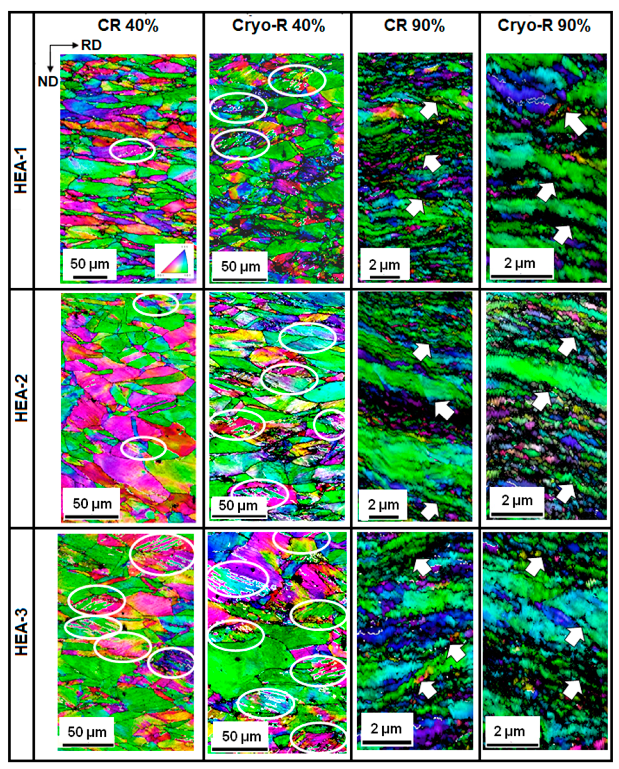
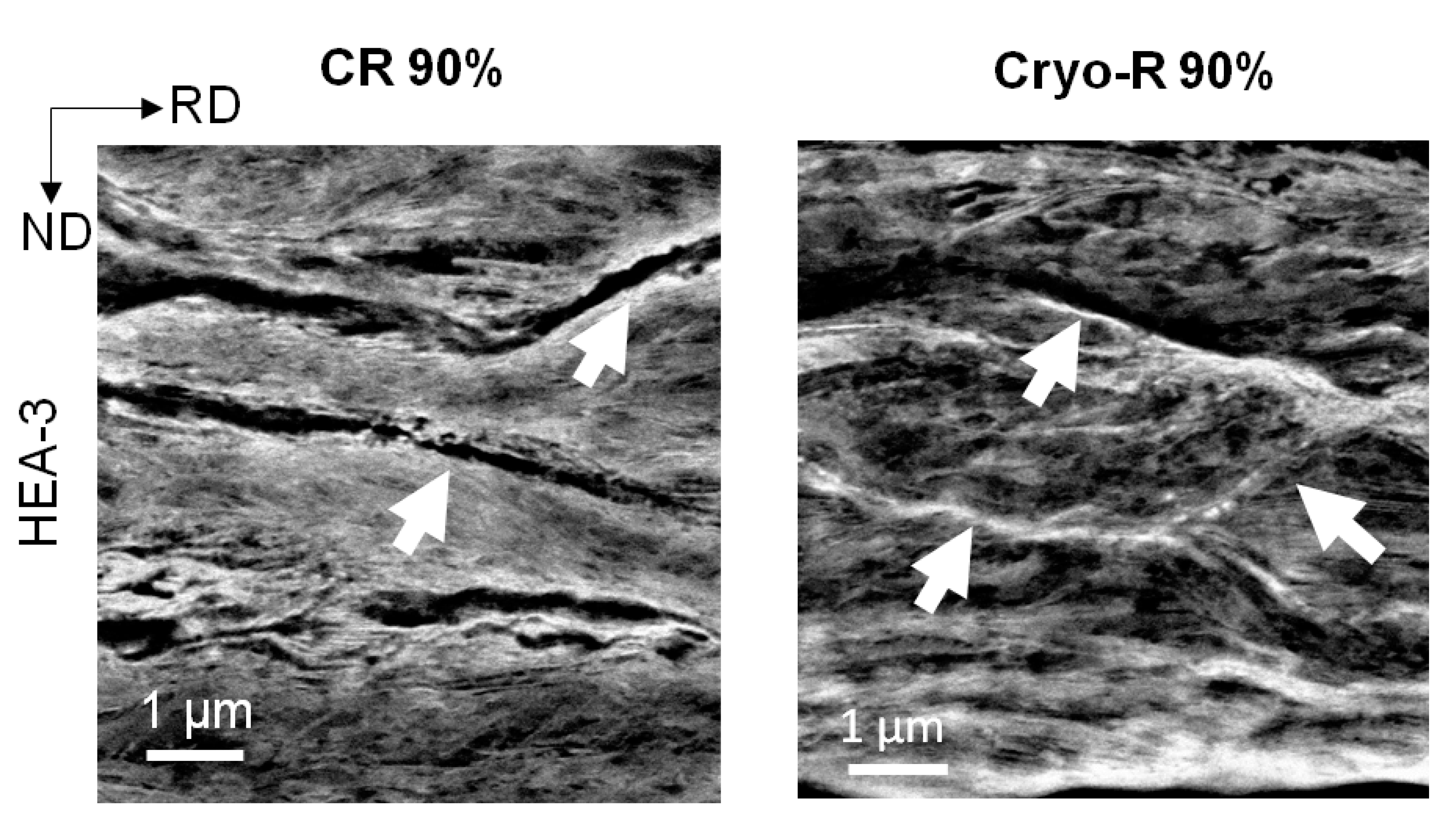
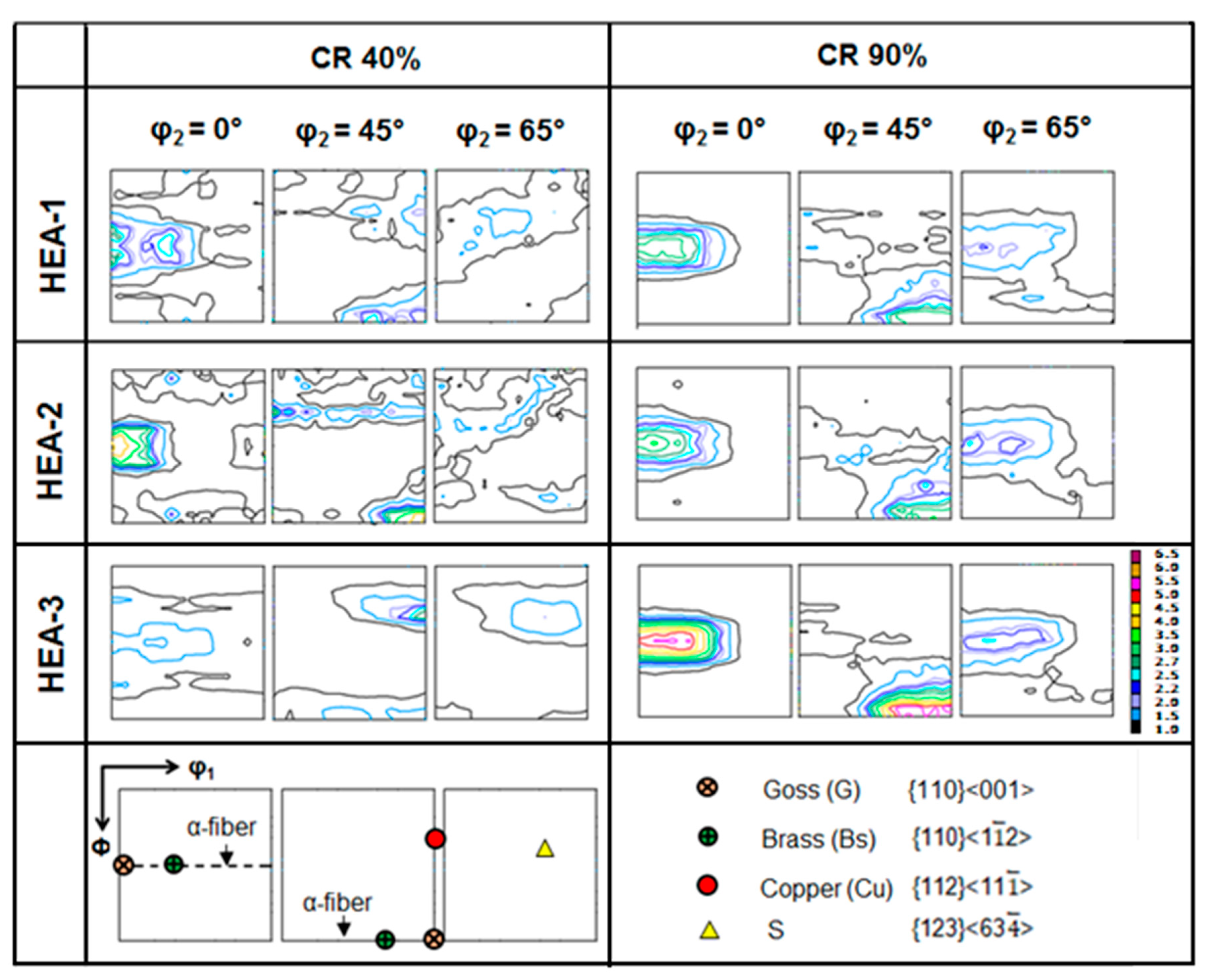
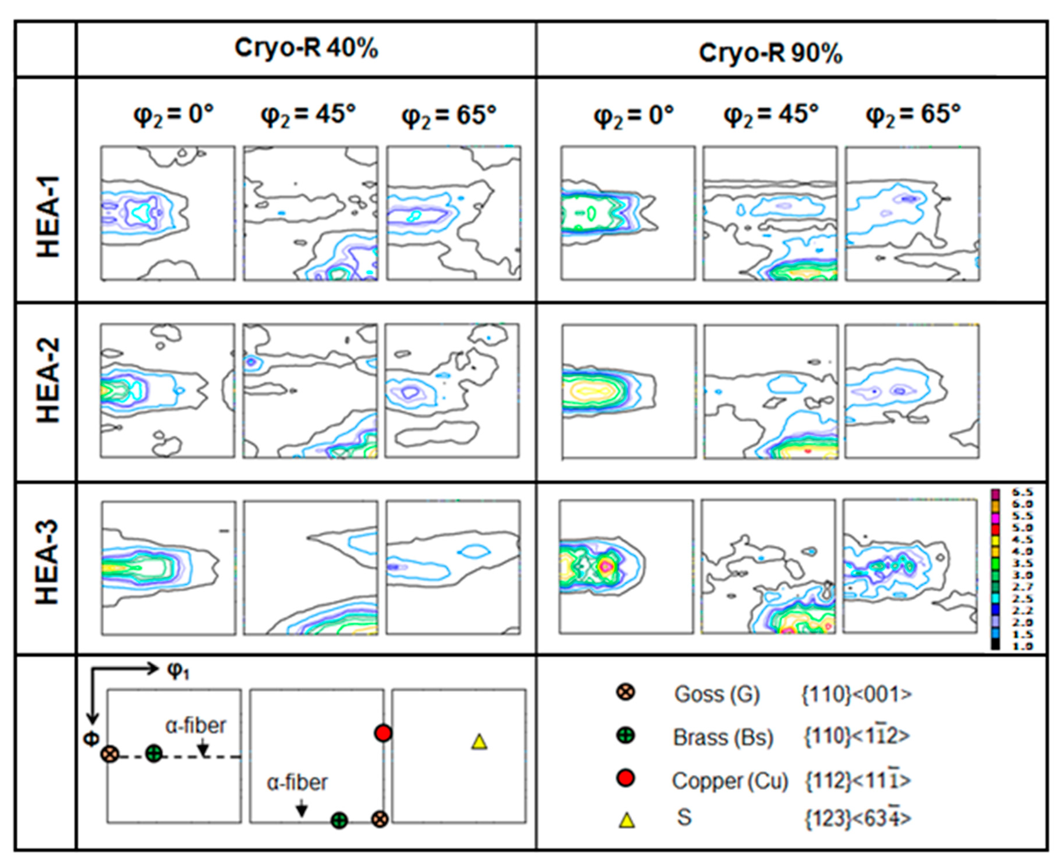
  • Mechanical twinning and shear banding at intermediate and high rolling reductions, respectively, is related to the formation of the Bs-type rolling texture in the low SFE HEAs investigated. However, partial dislocation slip and SRO-assisted planar slip may have contributed, too.
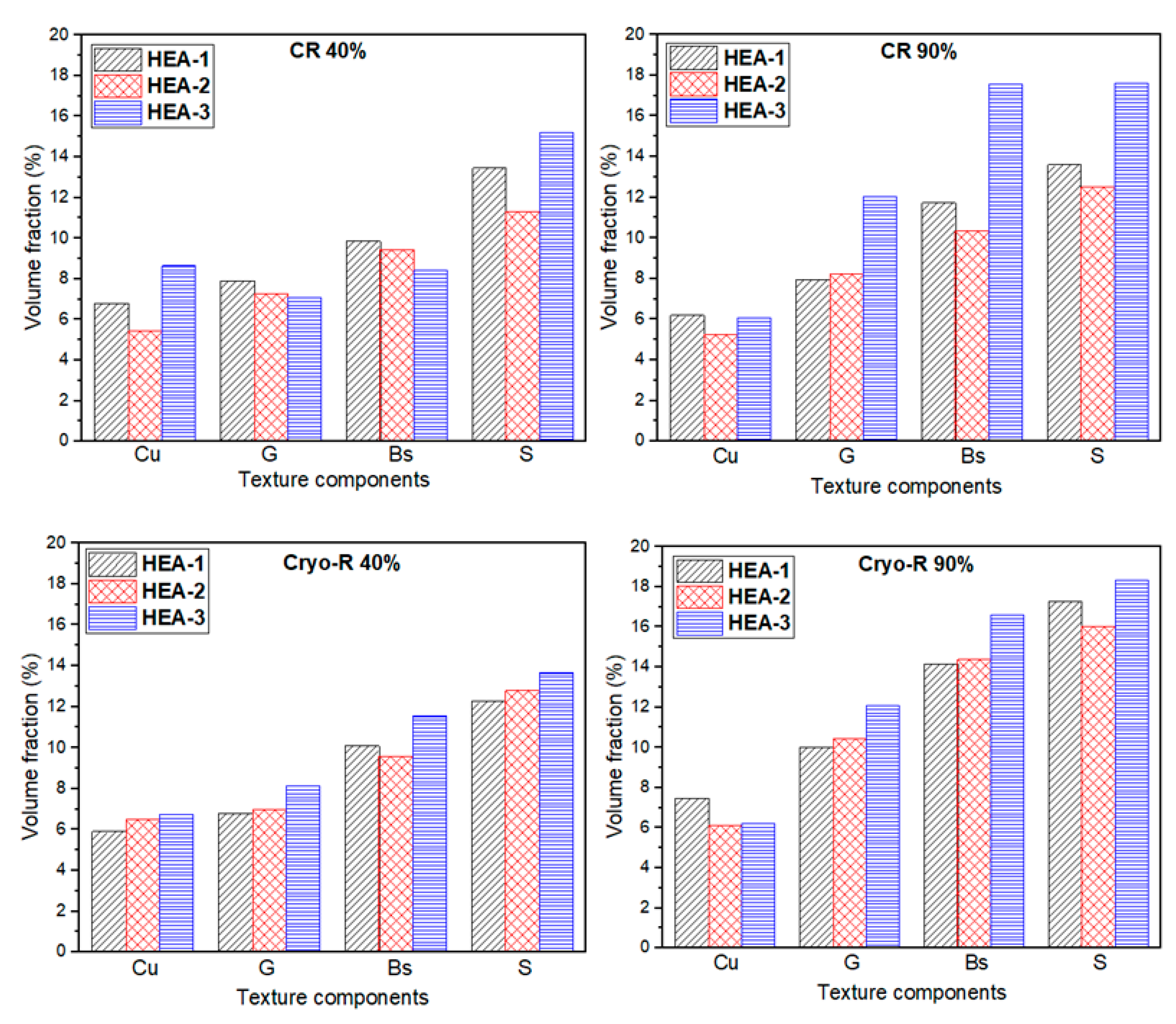
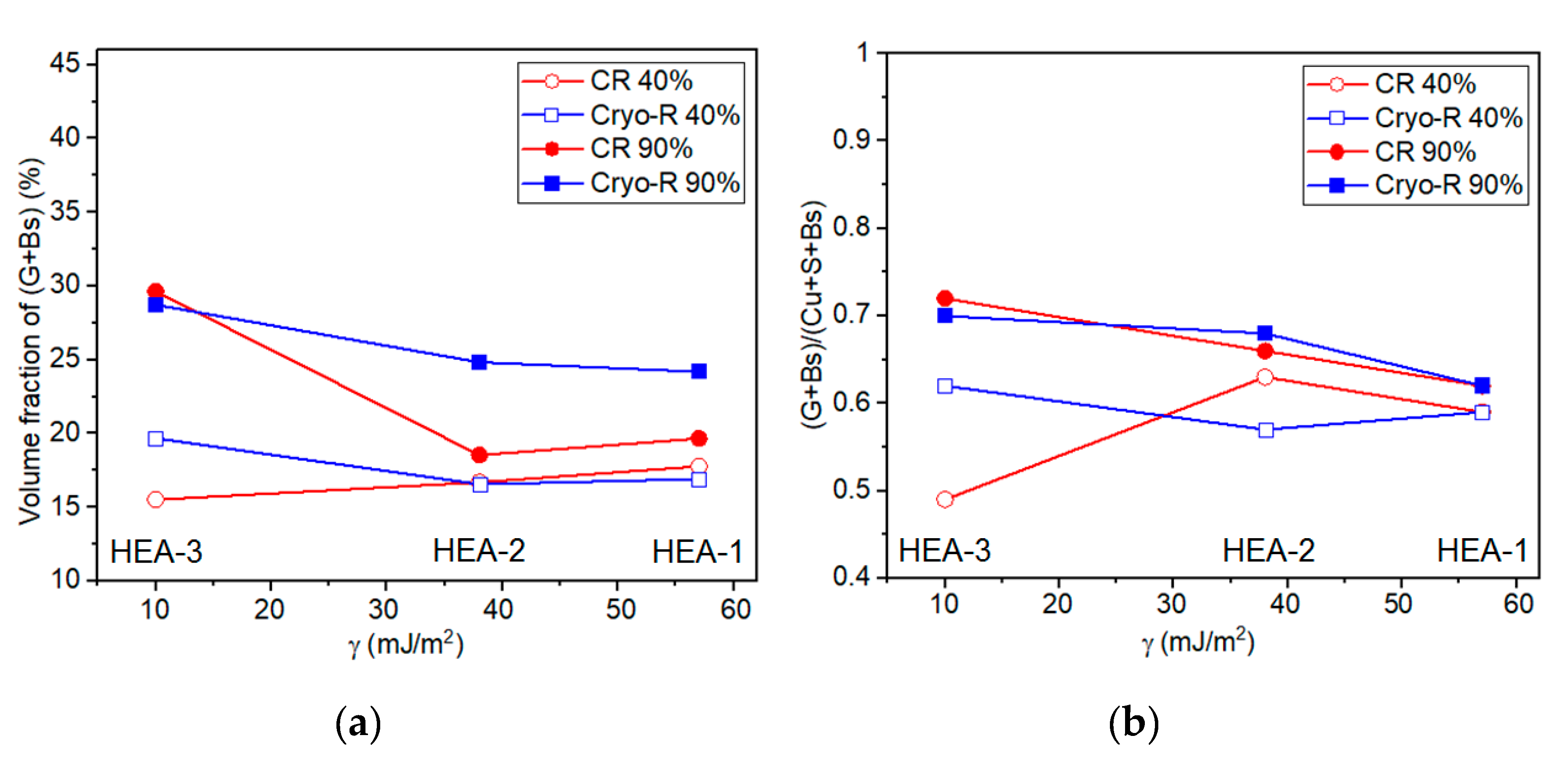
  • The Bs-type texture character strengthens with decreasing SFE. This effect is clearly seen for the 90% rolling reduction.
  • The texture evolution in the HEAs studied is similar to that observed for conventional FCC metal alloys with a low SFE.

Author Contributions

Conceptualization, S.S., W.S. and G.D.S.; methodology, S.S., W.S. and G.D.S.; software, G.D.S. and R.K.; validation, formal analysis, G.D.S. and W.S.; investigation, G.D.S. and R.K.; writing—review and editing, W.S., G.D.S. and S.S.; supervision, W.S. and S.S.; funding acquisition, S.S. All authors have read and agreed to the published version of the manuscript.

Funding

The funding for this research was obtained through the fellowship of GDS, and Friedrich Wilhelm Bessel award of SS by Alexander von Humboldt Foundation and Open Access Funding by the Publication Fund of the TU Dresden.

Acknowledgments

G. Dan Sathiaraj acknowledges the research fellowship of the Alexander von Humboldt Foundation, allowing his stay at Technische Universität Dresden. Satyam Suwas expresses his gratitude to the Alexander von Humboldt foundation for his stay at the Technische Universität Dresden as a Friedrich Wilhelm Bessel awardee. The authors are grateful to H.T. Reiter for sample cutting.

Conflicts of Interest

The authors declare no conflict of interest.

References

  1. Yeh, J.W.; Chen, S.K.; Lin, S.J.; Gan, J.Y.; Chin, T.S.; Shun, T.T.; Tsau, C.H.; Chang, S.Y. Nanostructured high-entropy alloys with multiple principal elements: Novel alloy design concepts and outcomes. Adv. Eng. Mater. 2004, 6, 299–303. [Google Scholar] [CrossRef]
  2. Yeh, J.W. Alloy design strategies and future trends in high-entropy alloys. JOM 2013, 65, 1759–1771. [Google Scholar] [CrossRef]
  3. Greer, A.L. Confusion by design. Nature 1993, 366, 303–304. [Google Scholar] [CrossRef]
  4. Ranganathan, S. Alloyed pleasures: Multimetallic cocktails. Curr. Sci. India 2003, 85, 1404–1406. [Google Scholar]
  5. Cantor, B.; Chang, I.T.H.; Knight, P.; Vincent, A.J.B. Microstructural development in equiatomic multicomponent alloys. Mater. Sci. Eng. A 2004, 213, 375–377. [Google Scholar] [CrossRef]
  6. Otto, F.; Hanold, N.L.; George, E.P. Microstructural evolution after thermo mechanical processing in an equiatomic, single-phase CoCrFeMnNi high entropy alloy with special focus on twin boundaries. Intermetallics 2014, 54, 39–48. [Google Scholar] [CrossRef]
  7. Gludovatz, B.; Hohenwarter, A.; Catoor, D.; Chang, E.H.; George, E.P.; Ritchie, R.O. A fracture-resistant high-entropy alloy for cryogenic applications. Science 2014, 345, 1153–1158. [Google Scholar] [CrossRef] [Green Version]
  8. Schuh, B.; Mendez-Martin, F.; Völker, B.; George, E.P.; Clemens, H.; Pippan, R.; Hohenwarter, A. Mechanical properties, microstructure and thermal stability of a nanocrystalline CoCrFeMnNi high-entropy alloy after severe plastic deformation. Acta Mater. 2015, 96, 258–268. [Google Scholar] [CrossRef] [Green Version]
  9. Miracle, D.B.; Miller, J.D.; Senkov, O.N.; Woodward, C.; Uchic, M.D.; Tiley, J. Exploration and development of high entropy alloys for structural applications. Entropy 2014, 16, 494–525. [Google Scholar] [CrossRef]
  10. Senkov, O.; Scott, J.; Senkova, S.; Meisenkothen, F.; Miracle, D.; Woodward, C. Microstructure and elevated temperature properties of a refractory TaNbHfZrTi alloy. J. Mater. Sci. 2012, 47, 4062–4074. [Google Scholar] [CrossRef]
  11. Senkov, O.; Senkova, S.; Woodward, C.; Miracle, D. Low-density, refractory multi-principal element alloys of the CrNbTiVZr system: Microstructure and phase analysis. Acta Mater. 2013, 61, 1545–1557. [Google Scholar] [CrossRef]
  12. Yao, M.J.; Pradeep, K.G.; Tasan, C.C.; Raabe, D. A novel, single phase, non-equiatomic FeMnNiCoCr high-entropy alloy with exceptional phase stability and tensile ductility. Scr. Mater. 2014, 72–73, 5–8. [Google Scholar] [CrossRef]
  13. Lu, Y.; Dong, Y.; Guo, S.; Jiang, L.; Kang, H.; Wang, T.; Wen, B.; Wang, Z.; Jie, J.; Cao, Z.; et al. A promising new class of high-temperature alloys: Eutectic high-entropy alloys. Sci. Rep. 2015, 4, 6200. [Google Scholar] [CrossRef]
  14. Moon, J.; Hong, S.I.; Bae, J.W.; Jang, M.J.; Yim, D.; Kim, H.S. On the strain rate dependent deformation mechanism of CoCrFeMnNi high-entropy alloy at room and liquid nitrogen temperature. Mater. Res. Lett. 2017, 5, 472–477. [Google Scholar] [CrossRef] [Green Version]
  15. Cantor, B. Multicomponent and high entropy alloys. Entropy 2014, 16, 4749–4768. [Google Scholar] [CrossRef] [Green Version]
  16. Wu, Z.; Bei, H.; Pharr, G.M.; George, E.P. Temperature dependence of the mechanical properties of equiatomic solid solution alloys with face-centered cubic crystal structures. Acta Mater. 2014, 81, 428–441. [Google Scholar] [CrossRef]
  17. Moon, J.; Qi, Y.; Tabachnikova, E.; Estrin, Y.; Choi, W.M.; Joo, S.H.; Lee, B.J.; Podolskiy, A.; Tikhonovsky, M.; Kim, H.S. Deformation-induced phase transformation of Co20Cr26Fe20Mn20Ni14 high-entropy alloy during high-pressure torsion at 77 K. Mater. Lett. 2017, 202, 86–88. [Google Scholar] [CrossRef]
  18. Li, Z.; Pradeep, K.G.; Deng, Y.; Raabe, D.; Tasan, C.C. Metastable high-entropy dual-phase alloys overcome the strength-ductility trade-off. Nature. 2016, 534, 227. [Google Scholar] [CrossRef]
  19. Deng, Y.; Tasan, C.C.; Pradeep, K.G.; Springer, H.; Kostka, A.; Raabe, D. Design of a twinning-induced plasticity high entropy alloy. Acta Mater. 2015, 94, 124–133. [Google Scholar] [CrossRef]
  20. Pradeep, K.G.; Tasan, C.C.; Yao, M.J.; Deng, Y.; Springer, H.; Raabe, D. Non-equiatomic high entropy alloys: Approach towards rapid alloy screening and property-oriented design. Mater. Sci. Eng. A 2015, 648, 183–192. [Google Scholar] [CrossRef]
  21. Tasan, C.C.; Deng, Y.; Pradeep, K.G.; Yao, M.J.; Springer, H.; Raabe, D. Composition dependence of phase stability, deformation mechanisms, and mechanical properties of the CoCrFeMnNi high-entropy alloy system. JOM 2014, 66, 1993–2001. [Google Scholar] [CrossRef]
  22. Zhang, C.; Zhu, C.; Harrington, T.; Casalena, L.; Wang, H.; Shin, S.; Vecchio, K.S. Multifunctional non-equiatomic high entropy alloys with superelastic, high damping, and excellent cryogenic properties. Adv. Eng. Mater. 2018, 1800941, 1–9. [Google Scholar] [CrossRef] [Green Version]
  23. Li, Z.; Raabe, D. Strong and ductile non-equiatomic high-entropy alloys: Design, processing, microstructure, and mechanical properties. JOM 2017, 69, 2099–2106. [Google Scholar] [CrossRef] [PubMed]
  24. Li, Z.; Tasan, C.C.; Deng, Y.; Pradeep, K.G.; Raabe, D. A TRIP-assisted dual-phase high-entropy alloy: Grain size and phase fraction effects on deformation behavior. Acta Mater. 2017, 131, 323–335. [Google Scholar] [CrossRef]
  25. Ma, D.; Yao, M.; Pradeep, K.G.; Tasan, C.C.; Springer, H.; Raabe, D. Phase stability of non-equiatomic CoCrFeMnNi high entropy alloys. Acta Mater. 2015, 98, 288–296. [Google Scholar] [CrossRef]
  26. Liu, S.F.; Wu, Y.; Wang, H.T.; He, J.Y.; Liu, J.B.; Chen, C.X.; Liu, X.J.; Wang, H.; Lu, Z.P. Stacking fault energy of face-centered cubic high entropy alloys. Intermetallics 2018, 93, 269–273. [Google Scholar] [CrossRef]
  27. Zaddach, A.J.; Scattergood, R.O.; Koch, C.C. Tensile properties of low-stacking fault energy high-entropy alloys. Mater. Sci. Eng. A. 2015, 636, 373–378. [Google Scholar] [CrossRef]
  28. Beyramali Kivy, M.; Asle Zaeem, M. Generalized stacking fault energies, ductilities, and twinnabilities of CoCrFeNi-based face-centered cubic high entropy alloys. Scripta Mater. 2017, 139, 83–86. [Google Scholar] [CrossRef]
  29. Park, N.; Li, X.; Tsuji, N. Microstructure and mechanical properties of Co21Cr22Cu22Fe21Ni14 processed by high pressure torsion and annealing. JOM 2015, 67, 2303–2309. [Google Scholar] [CrossRef]
  30. Nagase, T.; Todai, M.; Hori, T.; Nakano, T. Microstructure of equiatomic and non-equiatomic Ti-Nb-Ta-Zr-Mo high-entropy alloys for metallic biomaterials. J. Alloy Compd. 2018, 753, 412–421. [Google Scholar] [CrossRef]
  31. George, E.P.; Curtin, W.A.; Tasan, C.C. High entropy alloys: A focused review of mechanical properties and deformation mechanisms. Acta Mater. 2020, 188, 435–474. [Google Scholar] [CrossRef]
  32. Sathiaraj, G.D.; Pukenas, A.; Skrotzki, W. Texture formation in face-centered cubic high-entropy alloys. J. Alloy. Compd. 2020, 826, 154–183. [Google Scholar] [CrossRef]
  33. Okamoto, N.L.; Fujimoto, S.; Kambara, Y.; Kawamura, M.; Chen, Z.M.T.; Matsunoshita, H.; Tanaka, K.; Inui, H.; George, E.P. Size effect, critical resolved shear stress, stacking fault energy, and solid solution strengthening in the CrMnFeCoNi high-entropy alloy. Sci. Rep. 2016, 6, 35863. [Google Scholar] [CrossRef] [PubMed]
  34. Pawlik, K. Determination of the orientation distribution function from pole figures in arbitrarily defined cells. Phys. Stat. Sol. 1986, 134, 477–483. [Google Scholar] [CrossRef]
  35. Bunge, H.J. Texture Analysis in Materials Science: Mathematical Methods; Butterworth & Co: London, UK, 1982. [Google Scholar]
  36. Skrotzki, W.; Pukenas, A.; Odor, E.; Joni, B.; Ungar, T.; Völker, B.; Hohenwarter, A.; Pippan, R.; George, E.P. Microstructure, texture and strength development during high-pressure torsion of CrMnFeCoNi high-entropy alloy. Crystals 2020, 10, 336. [Google Scholar] [CrossRef]
  37. Allain, S.; Chateau, J.P.; Bouaziz, O.; Migot, S.; Guelton, N. Correlations between the calculated stacking fault energy and the plasticity mechanisms in Fe-Mn-C alloys. Mater. Sci. Eng. A 2004, 387, 158–162. [Google Scholar] [CrossRef]
  38. Remy, L.; Pineau, A. Twinning and strain-induced FCC→HCP transformation in the Fe-Mn-Cr-C system. Mater. Sci. Eng. 1977, 28, 99–107. [Google Scholar] [CrossRef]
  39. Leffers, T.; Ray, R. The brass-type texture and its deviation from the copper-type texture. Prog. Mater. Sci. 2009, 54, 351–396. [Google Scholar] [CrossRef]
  40. Wassermann, G. The effect of mechanical twinning on the formation of rolling textures in face-centered cubic metals. Z. Metallkd. 1963, 54, 61–65. [Google Scholar]
  41. Engler, O. Deformation and texture of copper-manganese alloys. Acta Mater. 2000, 48, 4827–4840. [Google Scholar] [CrossRef]
  42. Engler, O.; Pithan, C.; Lücke, K. Rolling texture development in Cu-Mn alloys. Mater. Sci. Forum. 1994, 157–162, 679–683. [Google Scholar] [CrossRef]
  43. Otto, F.; Dlouhy, A.; Somsen, C.; Bei, H.; Eggeler, G.; George, E.P. The influence of temperature and microstructure on the tensile properties of a CoCrFeMnNi high-entropy alloy. Acta Mater. 2013, 15, 5743–5755. [Google Scholar] [CrossRef] [Green Version]
  44. Tazuddin, A.; Biswas, K.; Gurao, N.P. Deciphering micromechanisms of plastic deformation in a novel single phase fcc-based MnFeCoNiCu high entropy alloy using crystallographic texture. Mater. Sci. Eng. A 2016, 657, 224–233. [Google Scholar] [CrossRef]
  45. Huang, S.; Li, W.; Lu, S.; Tian, F.; Shen, J.; Holmström, E.; Vitos, L. Temperature dependent stacking fault energy of FeCrCoNiMn high entropy alloy. Scr. Mater. 2015, 108, 44–47. [Google Scholar] [CrossRef]
  46. Ma, D.; Grabowski, B.; Körmann, F.; Neugebauer, J.; Raabe, D. Ab initio thermodynamics of the CoCrFeMnNi high entropy alloy: Importance of entropy contributions beyond the configurational one. Acta Mater. 2015, 100, 90–97. [Google Scholar] [CrossRef]
  47. Malin, A.S.; Hatherly, M.; Huber, J.; Welch, P. Microstructure and texture of rolled Copper-Silicon alloys. Z. Metallkd. 1982, 73, 489–494. [Google Scholar]
  48. Zhang, F.X.; Zhao, S.; Jin, K. Local structure and short-range order in a NiCoCr solid solution alloy. Phys. Rev. Lett. 2017, 118, 205501. [Google Scholar] [CrossRef] [PubMed] [Green Version]
  49. Tamm, A.; Aabloo, A.; Klintenberg, M.; Stocks, M.; Caro, A. Atomic-scale properties of Ni-based FCC ternary, and quaternary alloys. Acta Mater. 2015, 99, 307–312. [Google Scholar] [CrossRef] [Green Version]
Figure 1. X-ray diffractograms of high-entropy alloys (HEAs) 1–3 before (initial) and after the 90% rolling reduction at room temperature (CR 90%) and cryogenic temperature (Cryo-R 90%).
Crystals 10 00607 g001
Figure 2. Microstructure and texture of starting HEAs 1–3 represented by inverse pole figure (IPF) maps (black lines: high angle grain boundaries; white lines: Σ3 twin boundaries; color coding of the normal direction) and (111) pole figures (intensities are given in multiples of a random distribution: 1.0, 1.2, 1.5, 1.7, 2.0. RD = rolling direction; TD = transverse direction). The lower pole figure gives the position of the main rolling texture components {hkl} <uvw> ({rolling plane} <rolling direction>) of the FCC metals and alloys.
Crystals 10 00607 g002
Figure 3. Microstructure of cold-rolled (CR) and cryo-rolled (Cryo-R) HEAs 1–3 represented by IPF maps (black lines: high angle grain boundaries; white lines: Σ3 twin boundaries (bundles marked by ellipses); fine-scale shear bands marked by arrows; color coding of the normal direction).
Crystals 10 00607 g003
Figure 4. Backscatter electron (BSE) images of 90% cold- and cryo-rolled (CR and Cryo-R) HEA-3 sheets. Arrows mark shear bands and also cracks.
Crystals 10 00607 g004
Figure 5. Texture of cold-rolled (CR) HEAs 1–3 represented by φ2 = 0°, 45°, and 65° orientation distribution function (ODF) sections (intensities are given in multiples of a random distribution). Lower ODF sections give the position of the typical rolling components of face-centered cubic (FCC) metals and alloys.
Crystals 10 00607 g005
Figure 6. Texture of cryo-rolled (Cryo-R) HEAs 1–3 represented by φ2 = 0°, 45°, and 65° ODF sections (intensities are given in multiples of a random distribution). Lower ODF sections give the position of the typical rolling components of FCC metals and alloys.
Crystals 10 00607 g006
Figure 7. Volume fractions of the main texture components of 40% and 90% cold-rolled (CR) and cryo-rolled (Cryo-R) HEAs 1–3.
Crystals 10 00607 g007
Figure 8. (a) Volume fraction of the α-fiber components (G + Bs) and (b) the ratio of the volume fractions of the α-fiber (G + Bs) and β-fiber components (Cu + S + Bs) as a function of the stacking fault energy γ.
Crystals 10 00607 g008
Table 1. Composition of HEAs 1–3 and their stacking fault energies γ. Approximate normalized SFEs γ/Gb have been estimated by taking the shear modulus G and magnitude of the Burgers vector b of the equiatomic Cantor alloy [33].
HEACompositionγ (mJ/m2)γ/Gb (10−3)
HEA-1Cr14Mn20Fe20Co20Ni2657 [26]2.8
HEA-2Cr20Mn20Fe20Co15Ni2538 [26]1.9
HEA-3Cr18.5Mn18.5Fe18.5Co36Ni18.510 [27]0.5

