1. Introduction
Photon-pair sources based on spontaneous parametric down-conversion (SPDC) in nonlinear optic
χ(2) crystals are practical tools for experimental demonstrations of quantum metrology, quantum teleportation, quantum communication, and entanglement-based cryptography [
1]. Various crystal platforms (e.g.,
β-barium borate (
β-BaB
2O
4 or BBO), potassium dihydrogen phosphate (KH
2PO
4 or KDP), bismuth triborate (BiB
3O
6 or BiBO), and several periodically poled (PP) ferroelectric crystals, including lithium niobite (LiNbO
3 or LN) and potassium titanyl phosphate (KTiOPO
4 or KTP)) have been used for the SPDC based photon-pair sources since the first experimental demonstration using an ammonium dihydrogen phosphate (NH
4H
2PO
4 or ADP) crystal [
2,
3,
4,
5,
6,
7,
8,
9]. In particular, the pulsed pump SPDC source with the PPKTP Sagnac-loop configuration is known as a suitable platform for constructing practical quantum photonic networks, as it is advantageous for generating entangled photon pairs in the communication band [
10,
11,
12]. Nevertheless, photon-pair generation using borate crystals such as BBO and BiBO in the visible range is still attractive due to the feasibility of realizing multi-photon entanglement, as well as the spectral preference of single-photon detection efficiency [
7]. Since both physical and optical properties of borate crystals (e.g., hygroscopicity, transparency, birefringence, nonlinearity, and various causes of optical damage) generally depend on their crystal structures, it is always worthwhile to find another new borate crystal candidate to provide diversity and flexibility for SPDC-based quantum research [
13].
Recently Mutailipu et al. reported a new borate crystal, Ba
3Mg
3(BO
3)
3F
3 (or BMBF) that has two types of polymorphs: orthorhombic and hexagonal crystal systems, respectively [
14]. Of these two, the orthorhombic BMBF (the mm2 point symmetry,
Pna2
1) exhibits a large laser damage threshold (~6.2 GW/cm
2), a deep-UV cutoff edge (
λ~184 nm), a weak anisotropic thermal expansion, and the insolubility in water (i.e., the non-hygroscopicity unlike the BBO). These optical properties could be comparable or superior to that of commercial BBO. Second harmonic generation in a
Pna2
1-BMBF crystal was briefly discussed in [
14], but since the BMBF is a newly developed crystal, no further nonlinear optical applications have been studied yet. Therefore, it is timely to investigate the usefulness of
Pna2
1-BMBF as another suitable candidate for the generation of entangled photon pairs.
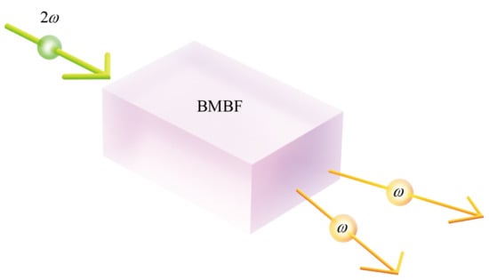
In this paper, we theoretically and numerically investigate the SPDC properties of
Pna2
1-BMBF for application as an entangled photon-pair source. In
Section 2, we theoretically describe two types of phase matching (PM) for the SPDC in a
Pna2
1-BMBF, i.e., Type I and Type II, where an input single photon (pump) with a frequency of 2
ω generates a pair of photons (signal and idler) with identical frequencies of
ω that are parallel (for Type I) or orthogonally (for Type II) polarized to each other. Then we discuss the group velocity (GV) matching between the interacting photon pulses, the effective nonlinearity in terms of
deff coefficient, and the spatial walk-off for the given wave vectors, followed by a theoretical brief of the biphoton joint spectrum and spectral purity.
Section 3 is devoted to discussing numerical simulation results, showing that the PM and GV matching conditions can be satisfied simultaneously over a specific range in the direction of pump wave vector. Thus, by sweeping the wave vector in this range, the resonant wavelength of pump that produces pure biphoton-states can be adjusted from 876.15 nm to 1052.77 nm for Type I and from 883.92 nm to 914.33 nm for Type II.
Here, we note that this condition is comparable to the extended phase matching (EPM) defined by Giovannetti et al. [
15,
16]. However, in Refs. [
15,
16], the simultaneous achievement of GV matching and quasi-phase matching (QPM) in a PP ferroelectric crystal is defined as the EPM, and in this case, the EPM can be satisfied only at one pump wavelength (and only one pump wave vector). In contrast, to the best of our knowledge, we report for the first time that the EPM can be achieved in the PM in a bulk mm2-biaxial crystal, as well as the QPM case in a PP crystal. In addition, we will also show that, in mm2-biaxial crystals, the EPM can be satisfied in a wide wavelength region (and in the specific range in the direction of pump wave vector), which is also contrasted with the cases of the uniaxial crystals in Refs. [
2,
3]. Of course, the spatial walk-off between the interacting beams occurs in our scheme, but this can be overcome by increasing the pump beam size. A larger pump beam window can be readily obtained by using thicker bulk crystals. In contrast, for the EPM using PP crystals, the crystal thickness (and the pump beam window) is limited by the maximum voltage that can be applied to the crystal during the periodic poling process. Since dielectric crystals are generally electrically conductive to some extent, if the voltage value required for the periodic poling exceeds the limit, the crystal burns and breaks during the fabrication process. In reality, the thickness of commercially available PPKTPs is about 0.5 mm [
17]. Compared to the previous EPM case, our scheme has the advantage that it can use a large beam window if necessary, does not require post-processing of crystals such as periodic polling, and has a wide wavelength range (several tens of nanometers) that satisfies the EPM. In contrast, for the EPM cases reported so far, the SPDC has only one resonant wavelength [
16,
18,
19,
20].
Next, we will discuss the numerical simulation results of the effective nonlinearity (
deff) and the spatial walk-off under the EPM, followed by the joint spectral analyses including the spectral purities calculated for several cases showing the largest nonlinearities. The results show that the calculated joint spectral amplitude (JSA) has a circular shape for Type II, and that photon-pairs can be generated with a high purity of 0.997 with a proper pump filtering. For Type I, the JSA shows a localized shape over a specific wavelength range even without pump filtering, and its purity is calculated as 0.833. Finally, the paper is summarized in
Section 4.
2. Material and Theories
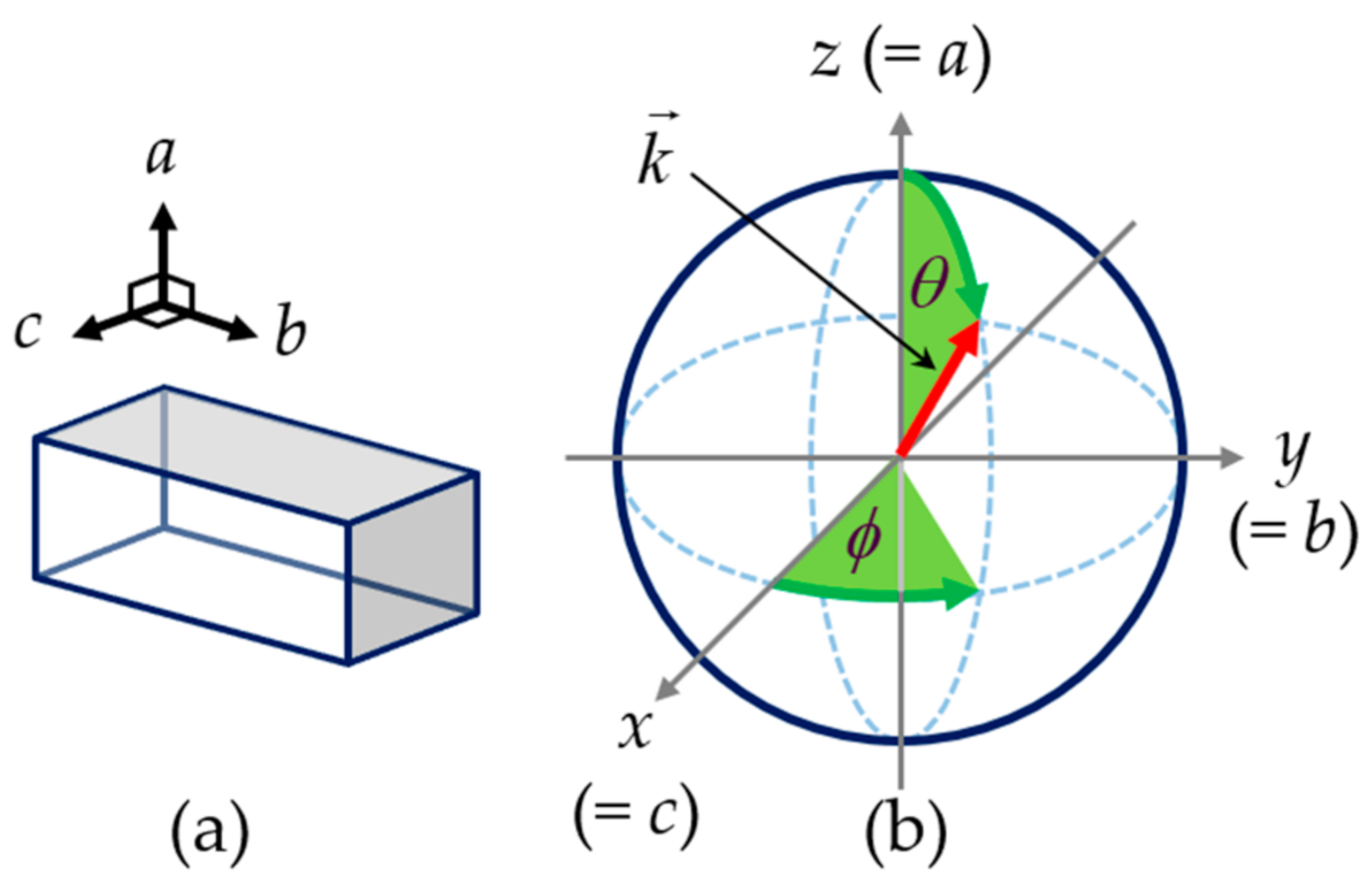
A
Pna2
1-BMBF has a point symmetry of orthorhombic mm2, and exhibits biaxial birefringence. The crystallographic axes of
Pna2
1-BMBF are all perpendicular to each other as shown in
Figure 1a, and the lattice constants are
a = 0.80740 nm,
b = 1.53072 nm, and
c = 0.88218 nm [
14]. Since Mutailipu et al.’s study, the relations between the crystallographic axes and their optic axes are defined as
x =
c,
y =
b, and
z =
a, and then the order of refractive-index magnitudes is given by
nx <
ny <
nz [
14]. Note the
c-axis is set to be parallel to the
x-axis. A schematic diagram showing the definition of the optical and crystallographic axes in the spherical coordinate is shown in
Figure 1b, where a wave vector representing the direction of beam propagation is also defined as:
Here,
ϕ and
θ are the azimuthal and polar angles, respectively. When light is incident into a BMBF crystal, the refractive indices (RI’s) of two eigen-polarization modes for the given
-direction can be obtained by solving the Fresnel equation of the wave normal as follows [
21],
where the definitions of parameters are:
Here,
q can be 1 or 2, then in the frequency-degenerate SPDC process,
n2ω and
nω represent the RI’s of pump photon with the frequency 2
ω and signal and idler photons with the same frequency
ω, respectively.
kx,
ky, and
kz in Equations (3) and (4) are defined in Equation (1).
p in Equation (2) can be
h or
l, representing high or low RI. Each of these corresponds to when taking minus and plus in the ± symbol of the denominator in Equation (2). The RI’s of
Pna2
1-BMBF (i.e.,
nx,
ny, and
nz) in Equation (5) are found in Ref. [
14]. In the BMBF, two types of PM are possible for the SPDC process, i.e., Type I and Type II, where an input single photon (pump) with a frequency of 2
ω generates a pair of photons (signal and idler) with identical frequencies of
ω that are parallel (for Type I) or orthogonally (for Type II) polarized to each other. The PM condition between pump, signal, and idler photons is given by
, and is classified into two types as follows:
When photons of different frequencies pass through a BMBF crystal, temporal walk-off (Δ
T) between interacting photons occurs due to their difference in GV. This GV mismatch is defined as Δ
T per unit crystal length as follows,
where,
L,
c and Δ
ng represent the crystal length, the speed of light in vacuum, and the group index difference between interacting photons, respectively. So, when Δ
ng = 0, the GV matching is satisfied, and for each type, it can be expressed as:
Then, the two types of EPM conditions are defined as when Equations (6) and (9) (for Type I), or Equations (7) and (10) (for Type II) are satisfied simultaneously. Each of the equations is a 3-variable function for pump wavelength (λp), θ, and ϕ, so by solving a system of equations (i.e., Equations (6) and (9), or Equations (7) and (10)) for a given λp, we can find a set of θ and ϕ, i.e., the direction of . Thus, by sweeping in the range of directions where the set of solutions exists, it is possible to continuously tune the resonant wavelength of the pump that produces pure biphoton-states. In contrast, for uniaxial crystals, is a 1-variable function of the angle (say, θ). Therefore, the PM and GV matching conditions are given as a 2-variable function of λp and θ, so they can have only one set of solutions of λp and θ. In other words, in uniaxial crystals, at most only one -direction can satisfy the EPM condition for a given wavelength. So, the SPDC using the EPM scheme in uniaxial crystals requires more tricky optical alignment than in biaxial crystals. For example, a pump laser with the exact EPM wavelength is required, and the beam must be aligned along the exact PM direction of the uniaxial crystal in experiments. In reality, however, the optical properties of the crystal depend on the manufacturer, so both θ for EPM and the corresponding λp also vary slightly. In contrast, in the case of biaxial crystals, λp for EPM can always be found for the given -direction in the range where the solution sets exist.
The BMBF is a biaxial birefringent crystal with a point symmetry mm2, and the crystallographic axes and the optical axes have the relationships of
x =
c,
y =
b, and
z =
a. In this case, the effective nonlinearity for a given
-direction is defined as [
22],
where the nonlinear optic coefficients are
d15 =
d31 = 0.09 pm/V,
d24 =
d32 = −0.39 pm/V, and
d33 = 0.51 pm/V when Kleinman symmetry conditions are valid [
14]. The subscript
i in Equation (11) can be 1 or 2, and represents Type I and Type II, respectively. Then the
ξ-coefficients for each type are given as:
Here, the angle-dependent parameters of
A,
B,
C,
G,
E, and
H are given by sin
θ, cos
θ, sin
ϕ, cos
ϕ, sin
δ, and cos
δ, respectively.
θ and
ϕ are defined in
Figure 1b.
δ is the angle introduced only for convenience and is defined as:
where
Vz represents the angle between the
z-axis and the optic axis of biaxial birefringence when the relation of
nx <
ny <
nz is valid, as in the case of the BMBF crystal.
Vz is related to Sellmeier equations of the crystal, and thus is wavelength-dependent. Therefore,
is also a 3-variable function for
λp,
θ, and
ϕ, so the effective nonlinearity of each type can be obtained by substituting the solution sets of
λp,
θ, and
ϕ that satisfy the corresponding EPM types. The SPDC efficiency is proportional to the square of the
deff coefficient for a given
-direction [
23].
When the interacting beams pass through a birefringent crystal, the spatial walk-off between the beams occurs due to the difference between the direction of beam propagation (
) and the direction of energy flow (Poynting vector,
), as well as due to the birefringence. Here, the angle
between
and
is given by,
where all parameters of Equation (15) are defined in Equations (1)–(5) [
21]. As discussed earlier in Equation (6), for Type I EPM, the pump photon with a low RI interacts with the high RI signal and idler photons with the same polarization state. In this case, the walk-off can be defined as the angle (
w) between the Poynting vectors of the interacting photons, and is given as [
24],
In the case of Type II EPM described by Equation (7), the walk-off angle
w is defined as the largest angle formed by the interacting beams. Since the low RI signal (or idler) beam (
) is always placed between the low RI pump beam (
) and the high RI idler (or signal) beam (
),
w for Type II can use the same definition as for Type I in Equation (16). As can be seen from Equation (15),
w is also the 3-variable function for
λp,
θ, and
ϕ, so
w of each type can be obtained by substituting the set of solutions of
λp,
θ, and
ϕ that satisfy the corresponding EPM types. Note that even with the same definition of
w, the calculation result is different for each type because the solution sets of
λp,
θ, and
ϕ depend on the EPM type. The maximum deviation between the interacting beams after passing through a crystal of length
L can be expressed as:
The construction of the signal-idler JSA and the calculation of the purity of biphoton state via Schmidt decomposition is a good way to quantify the heralded-state spectral purity of SPDC output. The biphoton state
generated from SPDC can be expressed as [
25],
where,
and
denote the creation operators of the signal and idler photons, respectively, and
ωs and
ωi are the corresponding frequencies. Here, the normalized correlation function
, representing the biphoton JSA, is expressed as the product of pump envelop function and the PM function as follows:
Assuming a pump with Gaussian spectral shape, the pump envelope (PE) function can be written as,
where
ωp and
σp represent the center frequency and bandwidth of the pump, respectively. The PM function is given in the form of a sinc-function as shown below,
where
L and Δ
k are the crystal length and the phase mismatch defined as
, respectively [
23]. For the given
-direction (i.e.,
θ and
ϕ) that satisfies each type of EPM, Equation (19) is given as a function of the signal and idler wavelengths (or
λs and
λi), so the JSA can be plotted on a two-dimensional plane as a function of
λs and
λi. The purity can be calculated via the following Schmidt decomposition,
where Schmidt coefficients,
cj, denote a set of non-negative real numbers satisfying the normalization condition,
.
and
represent the orthonormal basis states (i.e., Schmidt modes), respectively. Then the purity,
p, is defined as the sum of squares of Schmidt coefficients as [
25]:
So, once we plot the JSA as a function of λs and λi in a 2-dimensional plane, p can be calculated via the Schmidt decomposition in Equation (22).
3. Simulations and Discussion
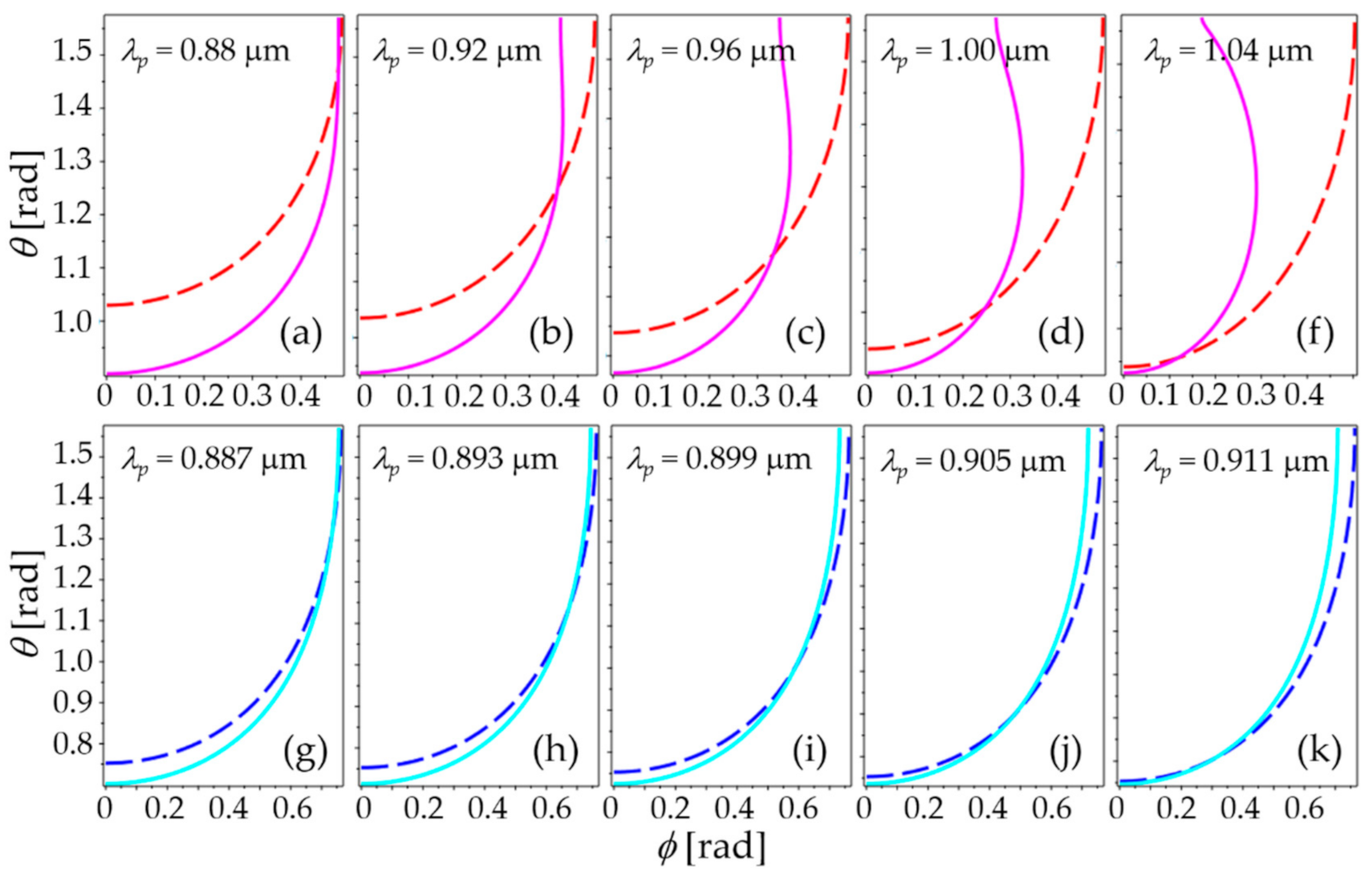
Figure 2 shows the numerical simulation results of the PM and GV matchings for Type I (
Figure 2a–f) and Type II (
Figure 2g–k). In each graph, the dotted and solid lines indicate the
-directions (
θ and
ϕ) that satisfy the PM and GV matching conditions for a given pump wavelength, respectively. The PM and GV matching curves were obtained by calculating Equations (6) and (9) (for Type I), or Equations (7) and (10) (for Type II). The intersection point of each graph means the
-direction satisfying the EPM, and appears over a wide wavelength range as expected in
Section 2.
Figure 3a shows the variation of the resonance pump wavelength (
λp) satisfying each type of EPM while sweeping
in space. Under each EPM condition,
λp spans 876.15 nm to 1052.77 nm for Type I, and 883.92 nm to 914.33 nm for Type II. So,
λp, which produces pure biphoton-states, can be continuously tuned by sweeping
in those ranges. The
-directions for the given EPM pump wavelength are plotted in
Figure 3b (for Type I) and
Figure 3c (for Type II) as a function of
θ and
ϕ. As plotted in
Figure 3b,c, for both types,
overall deviates more from the
z-axis at shorter wavelengths.
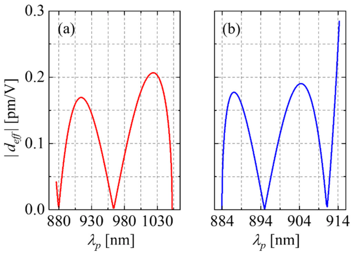
In order to find the
-direction for higher SPDC efficiency, we now discuss the effective nonlinearity of each EPM type. The effective nonlinear optic coefficients (
deff) are calculated numerically using Equation (11), the results are plotted in
Figure 4a (for Type I) and
Figure 4b (for Type II) as a function of
λp. Here, each
λp value is taken from the results in
Figure 3a, and corresponds to the EPM wavelength for the given
-direction. In
Figure 4a, the magnitude of
deff has maximum values at 914.3 nm and 1023.9 nm for Type I. For Type II,
deff values peak at 887.1 nm, 904.4 nm, and 914.33 nm, in particular the last one denotes when
ϕ = 0, i.e., when
lies on the
x-
z plane. The value of
deff at 914.33 nm is calculated to 0.28 pm/V for Type II, which is due to the large contribution of term
ξ22d24 in Equation (11) for a given
-direction. The maximum walk-off angles (
w), calculated using Equation (16) under EPM, are plotted in
Figure 5a (for Type I) and
Figure 5b (for Type II) as a function of the EPM
λp. Over the whole range of
λp, the calculated
w spans 1.23°–1.36° for Type I and 1.47°–1.53° for Type II. The corresponding deviations (Δ) of the interacting beams per unit crystal of length are about 23 μm/mm and 26 μm/mm, which can be sufficiently overcome by using a pump beam of a larger size in thick crystals. The EPM
λp for each peak
deff shown in
Figure 4,
-direction in terms of
θ and
ϕ, the corresponding
deff,
w, and Δ are summarized in
Table 1.
In order to quantify the heralded-state spectral purity of SPDC output, we now analyze the signal-idler JSA properties and calculate the purity of biphoton state.
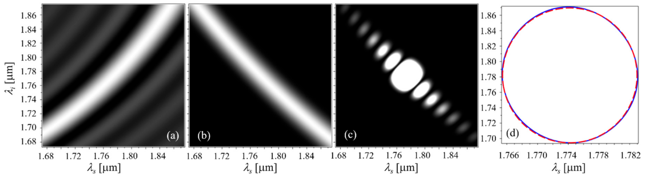
Figure 6 shows the joint spectral properties of the case (5) in
Table 1, i.e., Type II SPDC with the highest
deff. Note that in this case
lies on the
x-
z plane (i.e.,
ϕ = 0 in
Figure 1b), so the optical alignment is relatively easy compared to the other cases in
Table 1. The density plot of PM function shows typical EPM characteristics as in the case of the collinear, i.e., +45°, as plotted in
Figure 6a. The joint spectral intensity (JSI) calculated for the 8-nm bandwidth PE function (
Figure 6b) is plotted in
Figure 6c. Here, the JSI is defined as |JSA|
2. The solid and dashed lines in
Figure 6d represent the contour lines for JSI = 0.5 and a circle with a diameter of 27 nm, respectively. The contour line shows a circular shape, and the purity calculated using Schmidt decomposition in Equation (22) is as high as 0.997.
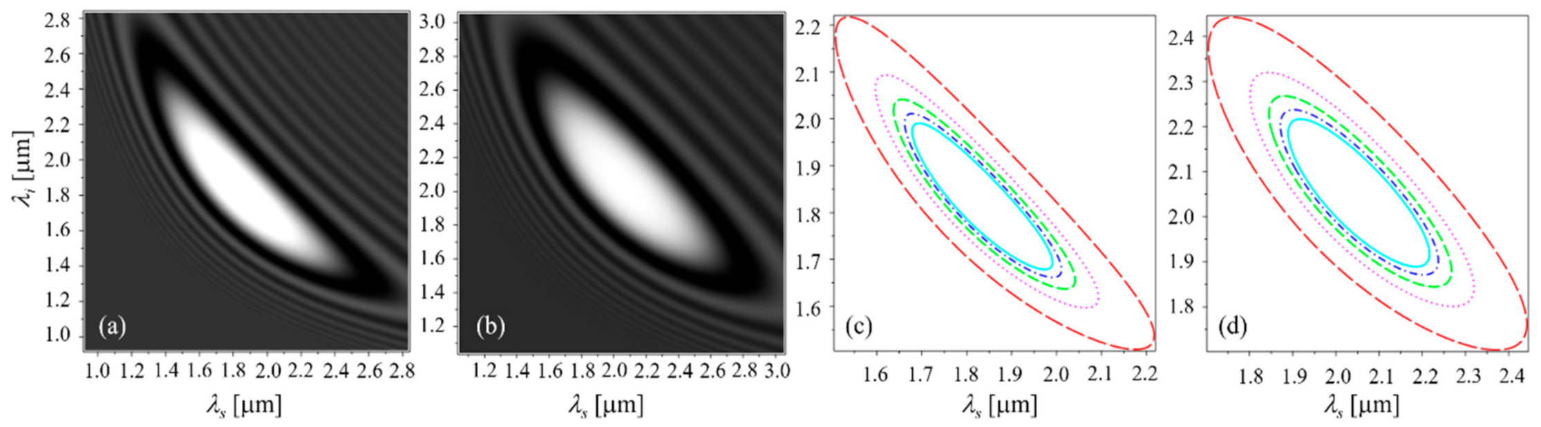
Figure 7 shows the JSI properties of cases (3) and (4) in
Table 1, where the PE functions of 5.2-nm and 7-nm bandwidth, respectively, were considered for higher purity. All results shown in
Figure 6 and
Figure 7 are calculated for a crystal length of 10 mm. The calculated JSI’s are plotted in
Figure 7a (for the case (3)) and
Figure 7c (for the case (4)). The contours of JSI = 0.5 shown in
Figure 7b,d exhibit circular shapes, and their diameters are 17.5 nm and 23 nm, respectively. The calculated spectral purity is as high as 0.997 for both cases.
For the Type I cases of (1) and (2) in
Table 1, the JSI’s show large, localized shapes around their SPDC resonances, as shown in
Figure 8a,b, without pump filtering. The calculated purities remain high as 0.726 and 0.833, respectively, even without pump filtering. The contours of JSI = 0.5 are plotted in
Figure 8c (for the case (1)) and
Figure 8d (for the case (2)), where the red long-dashed, magenta dotted, green dashed, blue dash-dotted, and cyan solid lines represent the results calculated for crystals of length 10, 20, 30, 40, and 50 mm, respectively. Since the resonance spectrum is inversely proportional to the crystal length, the area inside the contour line decreases as the crystal length increases, but the localized spectral shapes centered on the resonance point are maintained, as shown in
Figure 8c,d.
The entangled photon-pairs generated by the EPM SPDC in a Pna21- BMBF crystal have their resonances in a broad spectral range, and the calculation results show that quantum signal processing is feasible by choosing the spectral region of the photon-pairs within 2 μm. Since silica-based fibers still have transparency in this spectral region (e.g., silica fiber SM2000, Thorlabs, Newton, NJ, USA), we expect our research to provide flexibility and diversity in experimental quantum information processing using fiber-optic transmission lines, as well as free space quantum communication.


