Indium Tin-Oxide Wrapped 3D rGO and TiO2 Composites: Development, Characterization, and Enhancing Photocatalytic Activity for Methylene Blue


Abstract
:
1. Introduction
2. Results and Discussion
2.1. Construction of ITO-rGO and TiO2
2.2. Characterization of ITO-rGO and TiO2
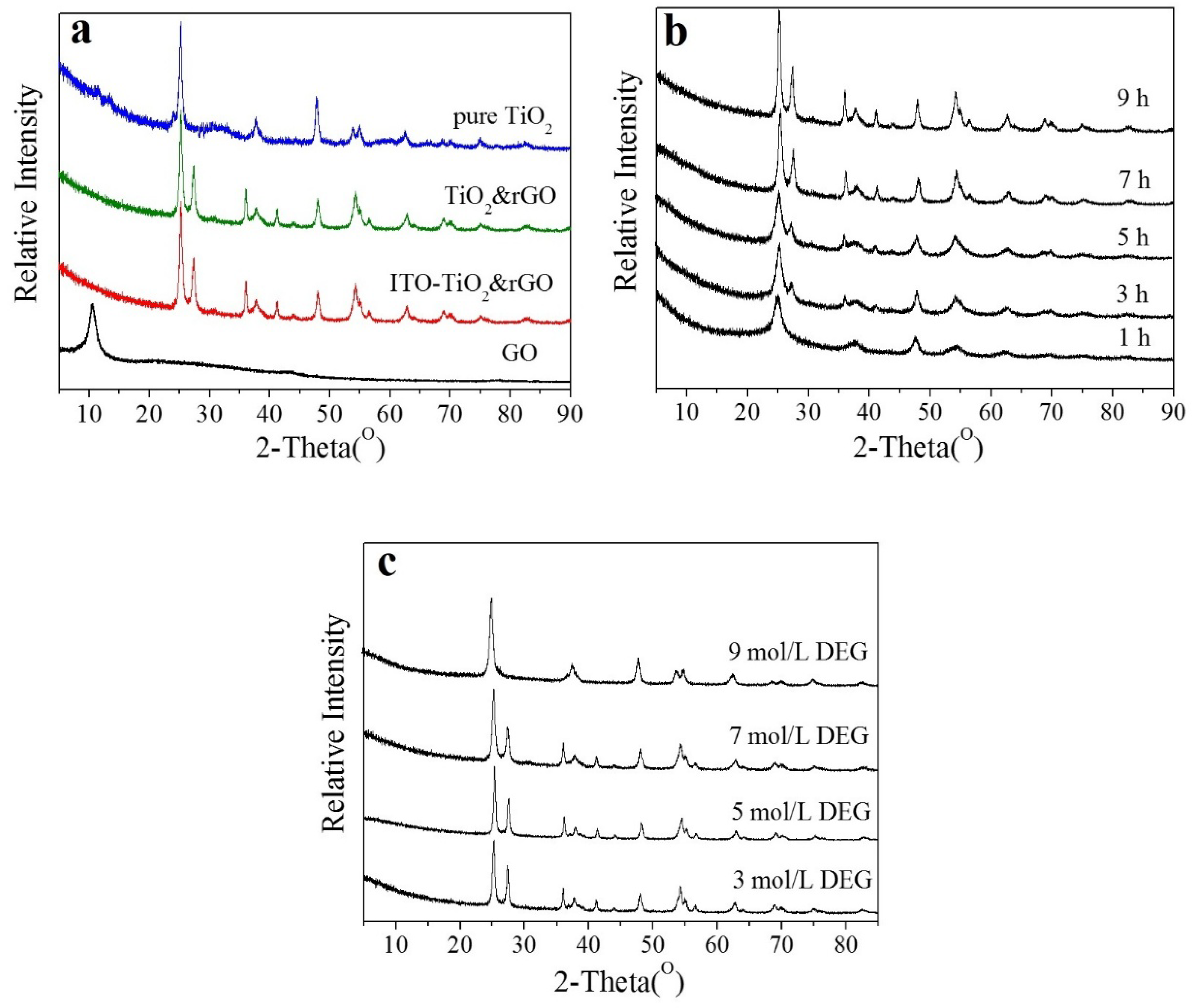
2.2.1. XRD
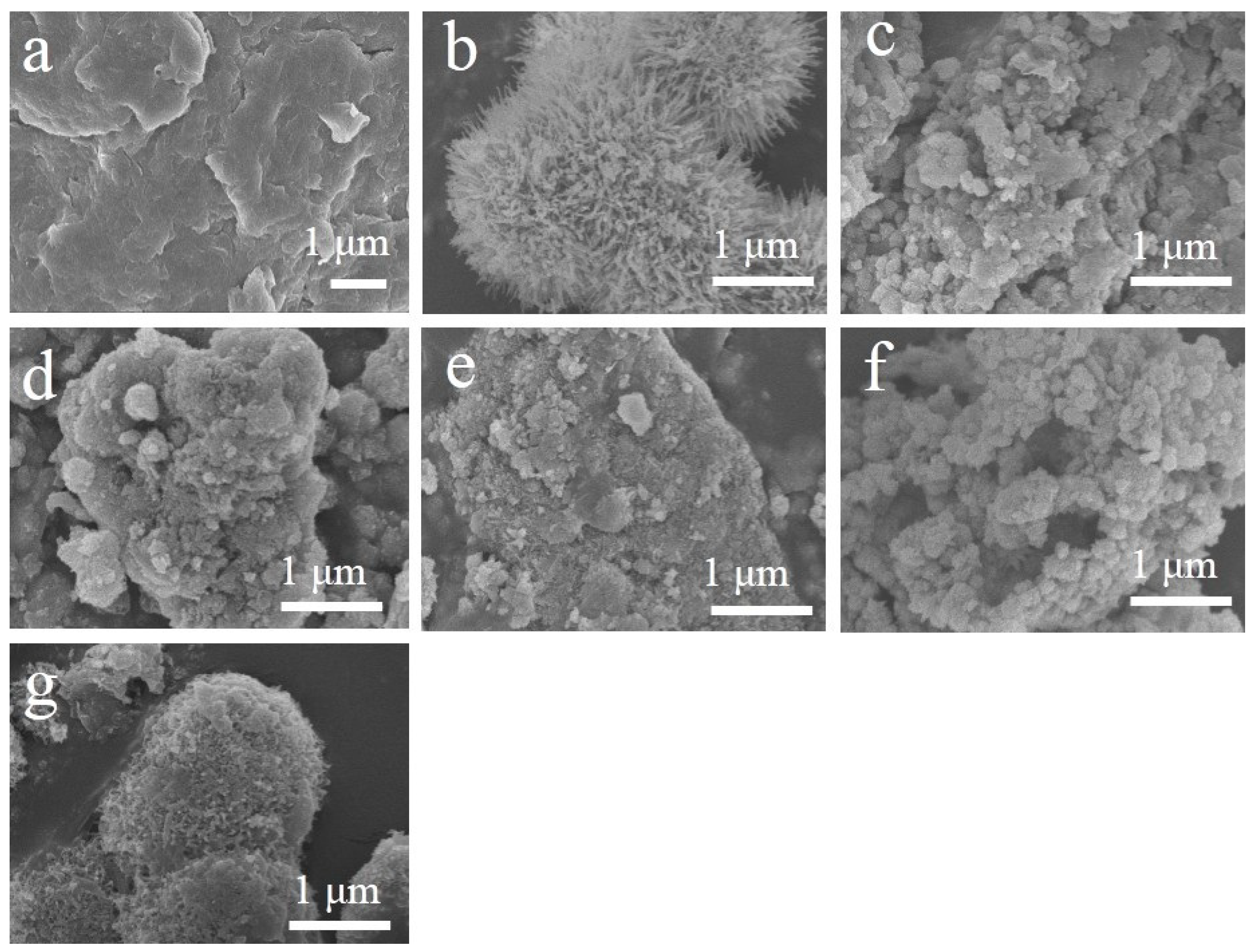
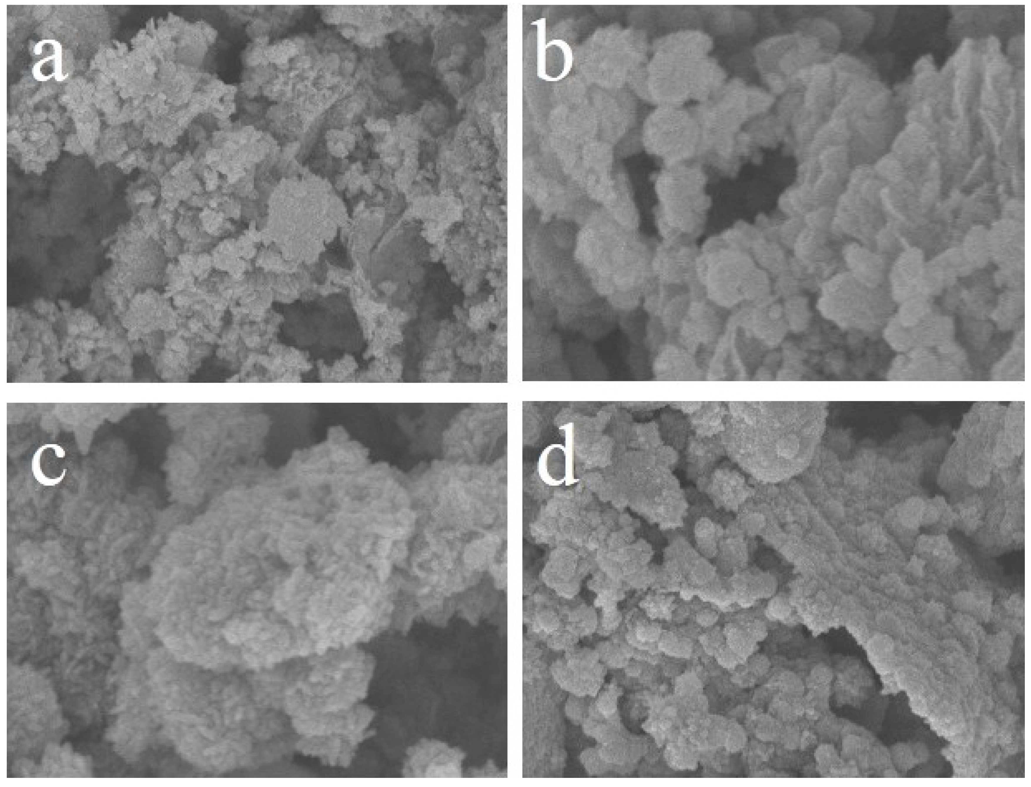
2.2.2. SEM
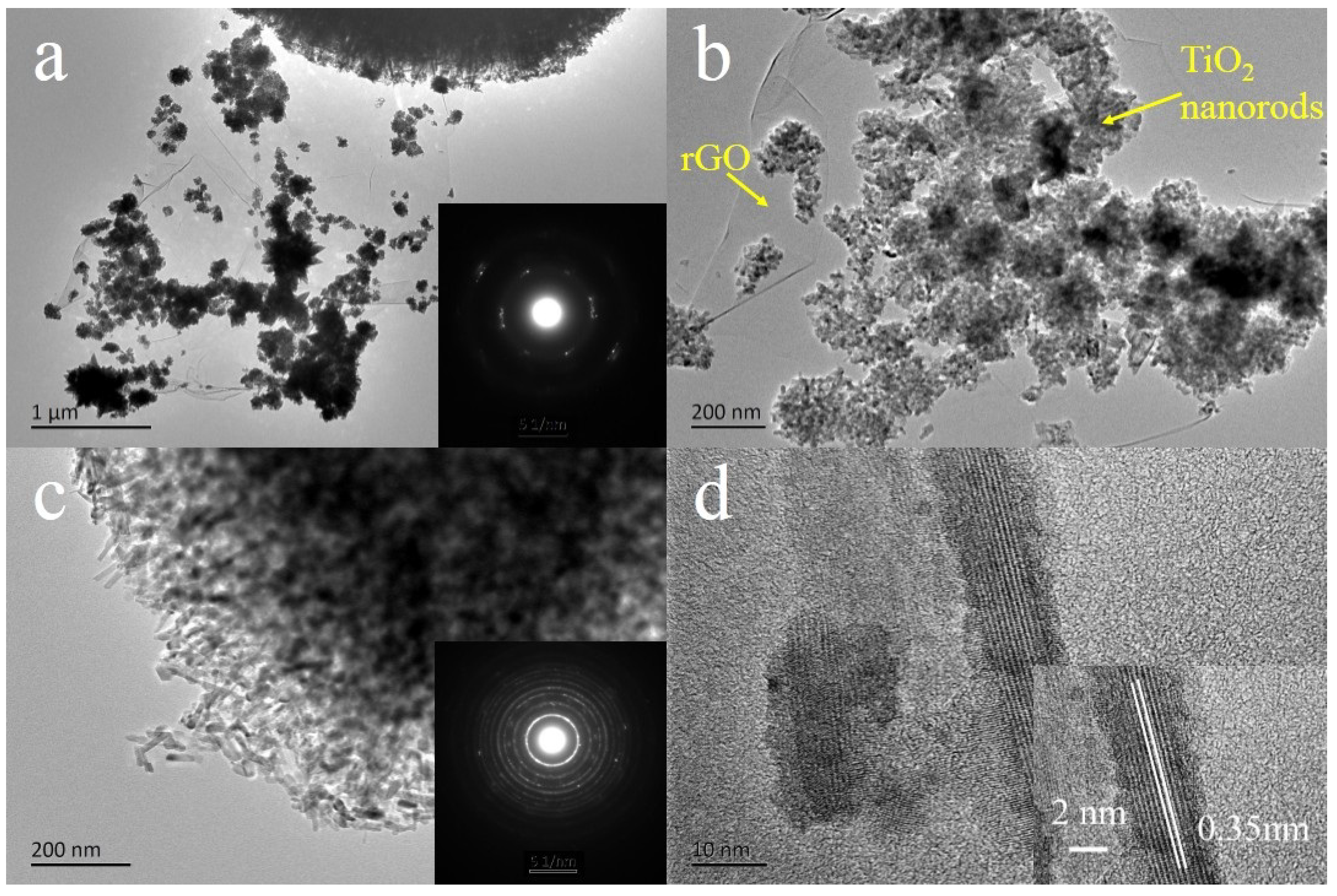
2.2.3. TEM
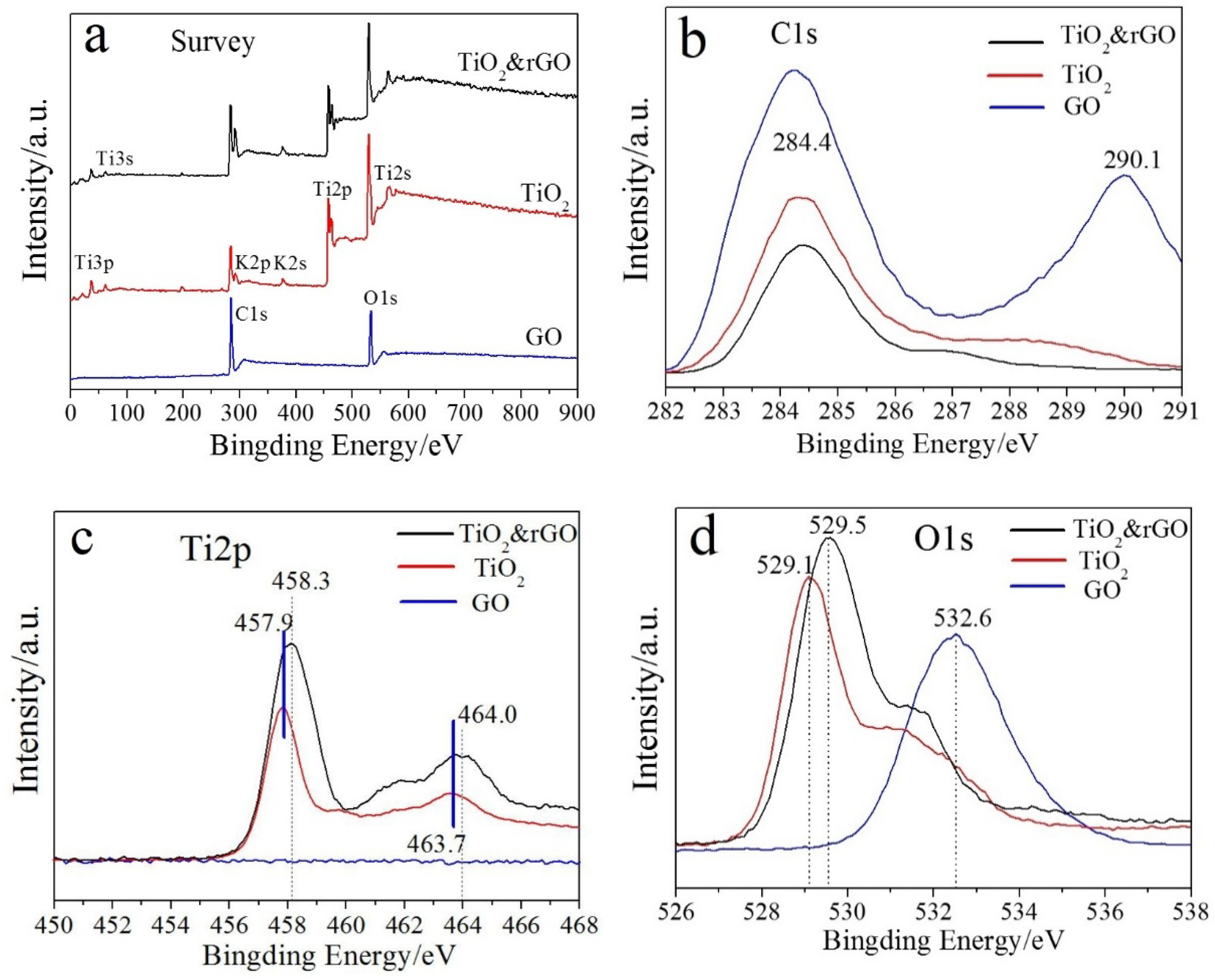
2.2.4. XPS
2.2.5. Raman Spectra
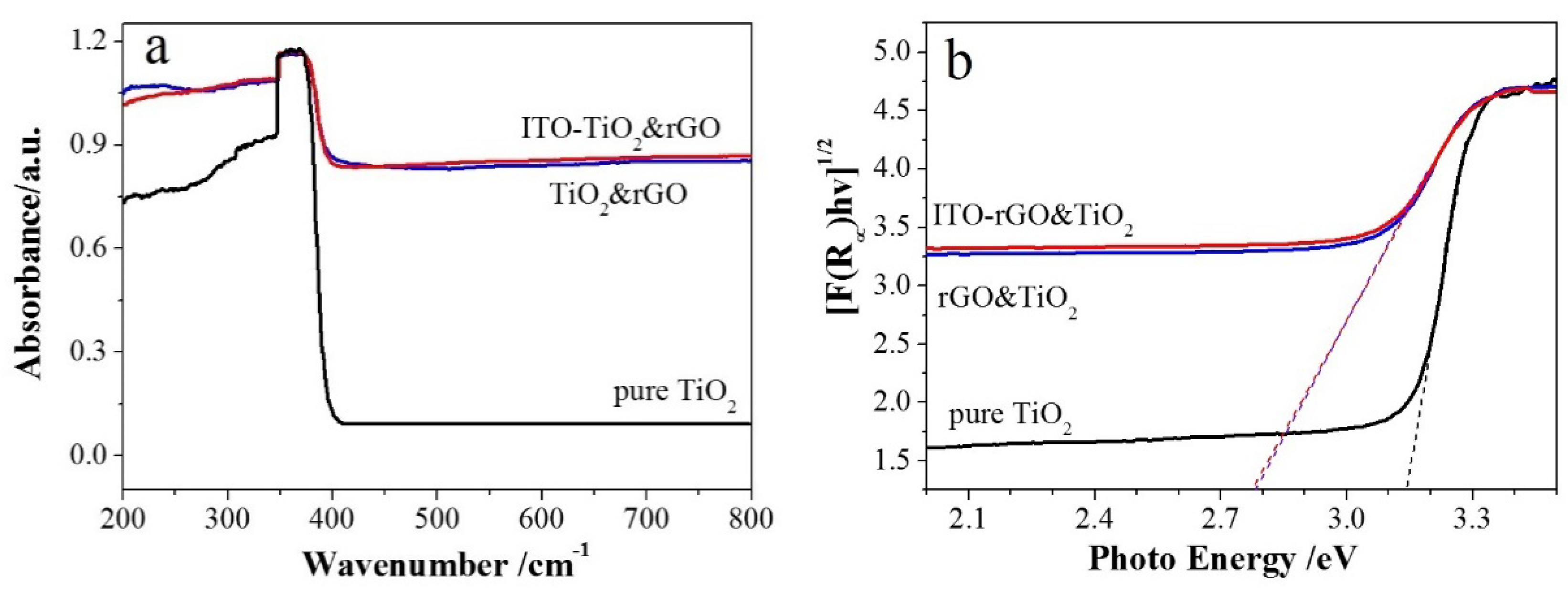
2.2.6. FT-IR and UV-Vis Spectra
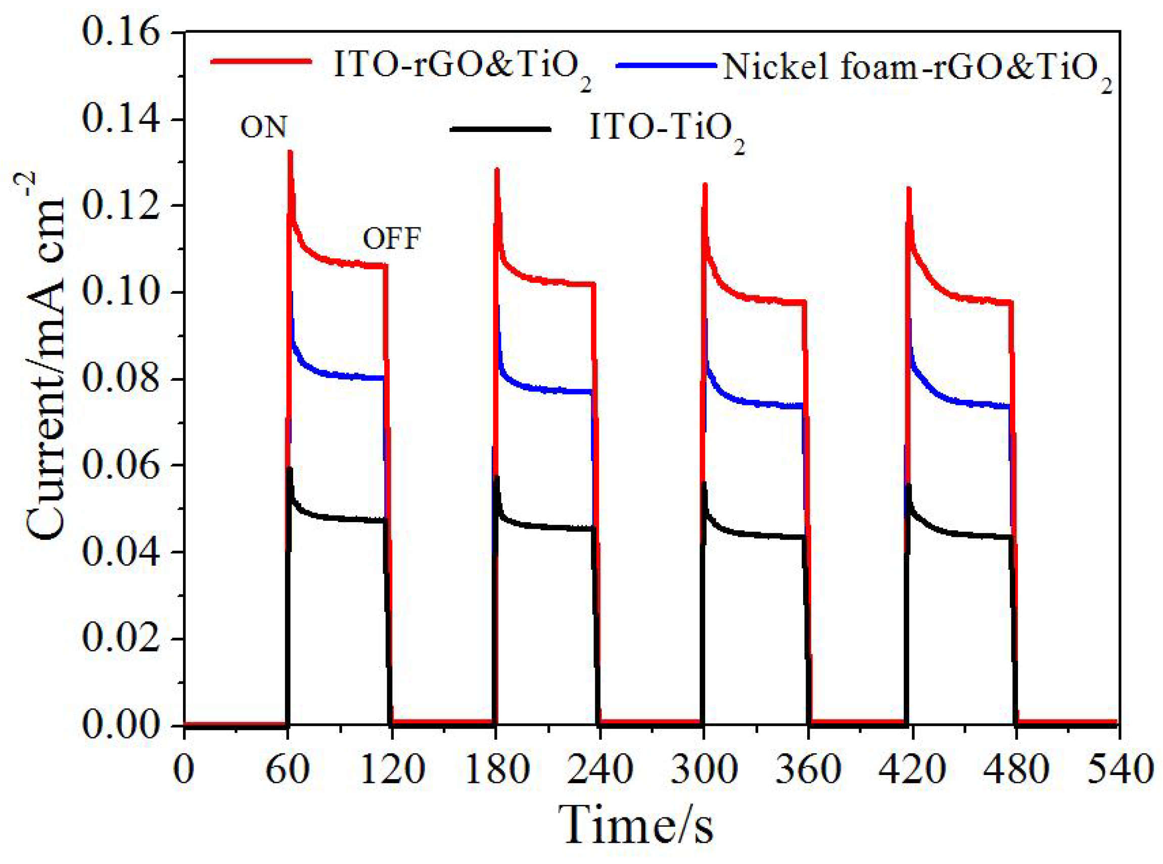
2.3. Photoelectrical Performance
2.4. Adsorption and Photocatalytic Properties
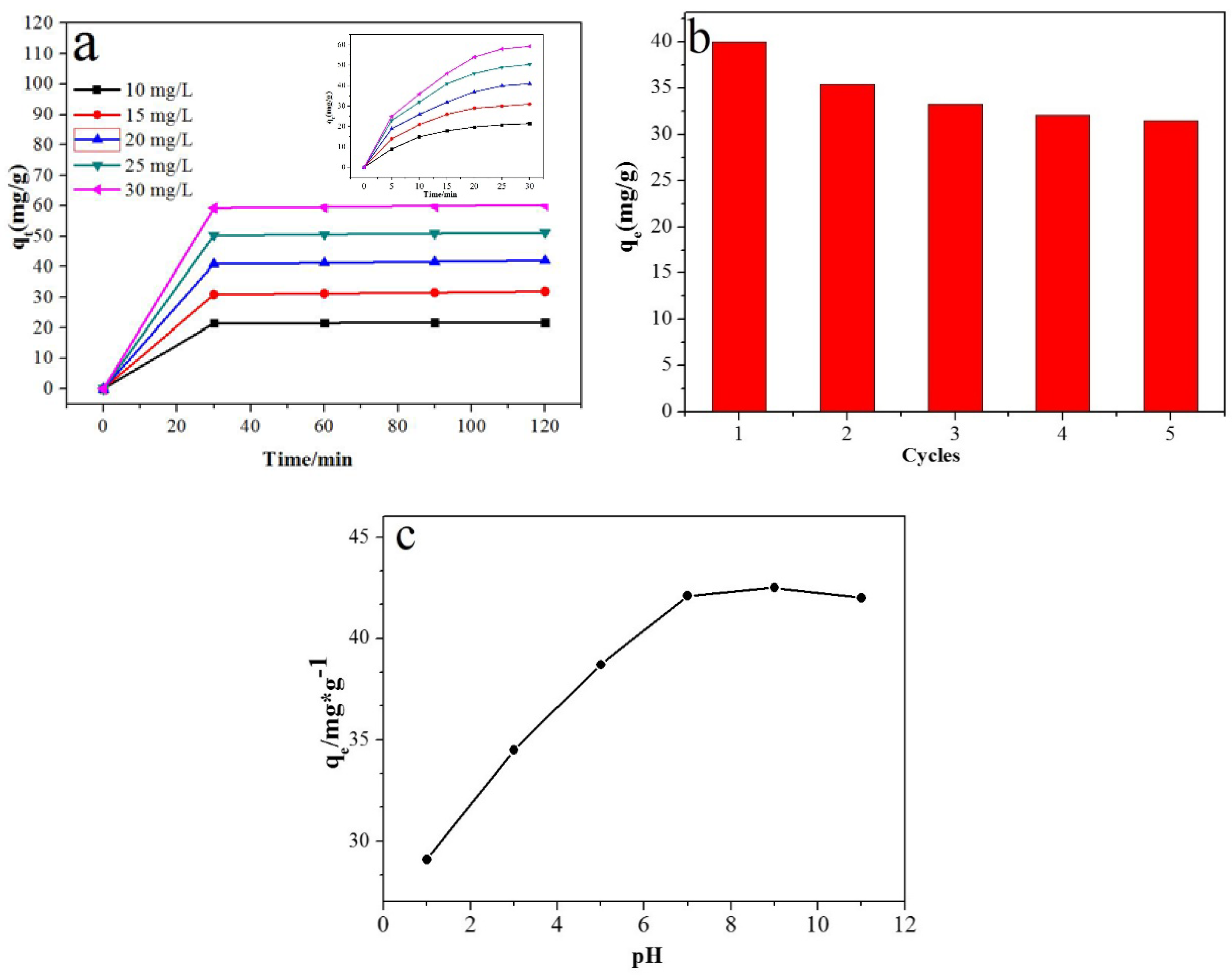
2.4.1. Adsorption Kinetics
2.4.2. Adsorption Thermodynamics
2.4.3. Adsorption Isotherm
2.4.4. Photocatalytic Activity
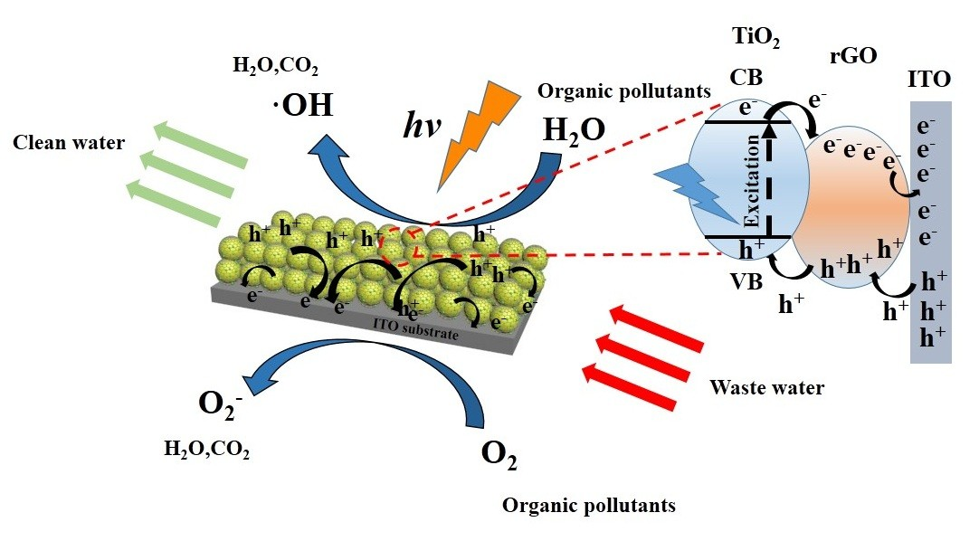
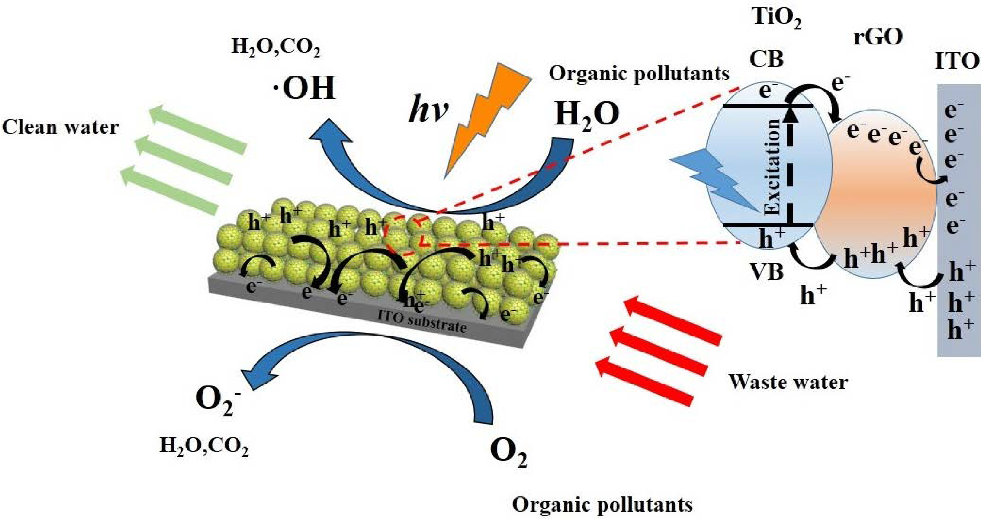
2.5. Mechanism of Degradation
3. Experimental Section
3.1. Materials
3.2. Preparation of rGO-TiO2
3.3. Fabrication of ITO-rGO and TiO2
3.4. Characterizations
3.5. Photoelectrical Performance
3.6. Photocatalytic Oxidation Reactions of ITO-rGO and TiO2
4. Conclusions
Supplementary Materials
Author Contributions
Funding
Conflicts of Interest
References
- Sambur, J.B.; Chen, T.; Choudhary, E.; Chen, G.; Nissen, E.J.; Thomas, E.M.; Zou, N.; Chen, P. Sub-particle reaction and photocurrent mapping to optimize catalyst-modified photoanodes. Nature 2016, 530, 77–80. [Google Scholar] [CrossRef] [PubMed]
- Butburee, T.; Bai, Y.; Wang, H.; Chen, H.; Wang, Z.; Liu, G.; Zou, J.; Khemthong, P.; Lu, G.Q.M.; Wang, L. 2D Porous TiO2 Single-Crystalline Nanostructure Demonstrating High Photo-Electrochemical Water Splitting Performance. Adv. Mater. 2018, 30, 1705666. [Google Scholar] [CrossRef] [PubMed]
- Menny, S.; Snir, D.; Sven, R.; Larissa, G.; Arie, Z. Core/CdS Quantum Dot/Shell Mesoporous Solar Cells with Improved Stability and Efficiency Using an Amorphous TiO2 Coating. J. Phys. Chem. C 2009, 113, 3895–3898. [Google Scholar]
- Wang, Y.; Gu, L.; Guo, Y.; Li, H.; He, X.; Tsukimoto, S.; Ikuhara, Y.; Wan, L. Rutile-TiO2 Nanocoating for a High-Rate Li4Ti5O12 Anode of a Lithium-Ion Battery. J. Am. Chem. Soc. 2012, 134, 7874–7879. [Google Scholar] [CrossRef] [PubMed]
- Scanlon, D.O.; Dunnill, C.W.; Buckeridge, J.; Shevlin, S.A.; Logsdail, A.J.; Woodley, S.M.; Catlow, C.R.A.; Powell, M.J.; Palgrave, R.G.; Parkin, I.P.; et al. Band alignment of rutile and anatase TiO2. Nat. Mater. 2013, 12, 798–801. [Google Scholar] [CrossRef]
- Tan, L.; Chai, S.; Mohamed, A.R. Synthesis and Applications of Graphene-Based TiO2 Photocatalysts. ChemSusChem 2012, 5, 1868–1882. [Google Scholar] [CrossRef] [PubMed]
- Faraldos, M.; Bahamonde, A. Environmental applications of titania-graphene photocatalysts. Catal. Today 2017, 285, 13–28. [Google Scholar] [CrossRef]
- Zhang, N.; Yang, M.; Liu, S.; Sun, Y.; Xu, Y. Waltzing with the Versatile Platform of Graphene to Synthesize Composite Photocatalysts. Chem. Rev. 2015, 115, 10307–10377. [Google Scholar] [CrossRef]
- Han, C.; Zhang, N.; Xu, Y. Structural diversity of graphene materials and their multifarious roles in heterogeneous photocatalysis. Nano Today 2016, 11, 351–372. [Google Scholar] [CrossRef]
- Lu, K.; Chen, Y.; Xin, X.; Xu, Y. Rational utilization of highly conductive, commercial Elicarb graphene to advance the graphene-semiconductor composite photocatalysis. Appl. Catal. B Environ. 2018, 224, 424–432. [Google Scholar] [CrossRef]
- Geim, A.K. Graphene: Status and Prospects. Science 2009, 324, 1530–1534. [Google Scholar] [CrossRef] [PubMed] [Green Version]
- Huang, X.; Yin, Z.; Wu, S.; Qi, X.; He, Q.; Zhang, Q.; Yan, Q.; Boey, F.; Zhang, H. Graphene-based materials: Synthesis, characterization, properties, and applications. Small 2011, 7, 1876–1902. [Google Scholar] [CrossRef] [PubMed]
- Tu, W.; Zhou, Y.; Zou, Z. Versatile Graphene-Promoting Photocatalytic Performance of Semiconductors: Basic Principles, Synthesis, Solar Energy Conversion, and Environmental Applications. Adv. Funct. Mater. 2013, 23, 4996–5008. [Google Scholar] [CrossRef]
- Xiang, Q.; Yu, J.; Jaroniec, M. Graphene-based semiconductor photocatalysts. Chem. Soc. Rev. 2012, 41, 782–796. [Google Scholar] [CrossRef] [PubMed]
- Li, Y.; Chen, J.; Huang, L.; Li, C.; Hong, J.; Shi, G. Highly Compressible Macroporous Graphene Monoliths via an Improved Hydrothermal Process. Adv. Mater. 2014, 26, 4789–4793. [Google Scholar] [CrossRef] [PubMed]
- Low, J.; Yu, J.; Ho, W. Graphene-Based Photocatalysts for CO2 Reduction to Solar Fuel. J. Phys. Chem. Lett. 2015, 6, 4244–4251. [Google Scholar] [CrossRef] [PubMed]
- Chen, C.; Cai, W.; Long, M.; Zhou, B.; Wu, Y.; Wu, D.; Feng, Y. Synthesis of Visible-Light Responsive Graphene Oxide/TiO2 Composites with p/n Heterojunction. ACS Nano 2010, 4, 6425–6432. [Google Scholar] [CrossRef]
- Tolosana-Moranchel, Á.; Manassero, A.; Satuf, M.L.; Alfano, O.M.; Casas, J.A.; Bahamonde, A. Influence of TiO2-rGO optical properties on the photocatalytic activity and efficiency to photodegrade an emerging pollutant. Appl. Catal. B Environ. 2019, 246, 1–11. [Google Scholar] [CrossRef]
- Pu, S.; Zhu, R.; Ma, H.; Deng, D.; Pei, X.; Qi, F.; Chu, W. Facile in-situ design strategy to disperse TiO2 nanoparticles on graphene for the enhanced photocatalytic degradation of rhodamine 6G. Appl. Catal. B Environ. 2017, 218, 208–219. [Google Scholar] [CrossRef]
- Yang, N.; Zhai, J.; Wang, D.; Chen, Y.; Jiang, L. Two-Dimensional Graphene Bridges Enhanced Photoinduced Charge Transport in Dye-Sensitized Solar Cells. ACS Nano 2010, 4, 887–894. [Google Scholar] [CrossRef]
- Dai, Y.; Jing, Y.; Zeng, J.; Qi, Q.; Wang, C.; Goldfeld, D.; Xu, C.; Zheng, Y.; Sun, Y. Nanocables composed of anatase nanofibers wrapped in UV-light reduced graphene oxide and their enhancement of photoinduced electron transfer in photoanodes. J. Mater. Chem. 2011, 21, 18174. [Google Scholar] [CrossRef]
- Huang, Q.; Tian, S.; Zeng, D.; Wang, X.; Song, W.; Li, Y.; Xiao, W.; Xie, C. Enhanced Photocatalytic Activity of Chemically Bonded TiO2/Graphene Composites Based on the Effective Interfacial Charge Transfer through the C-Ti Bond. ACS Catal. 2013, 3, 1477–1485. [Google Scholar] [CrossRef]
- Li, Z.; Huang, Z.; Guo, W.; Wang, L.; Zheng, L.; Chai, Z.; Shi, W. Enhanced Photocatalytic Removal of Uranium (VI) from Aqueous Solution by Magnetic TiO2/Fe3O4 and Its Graphene Composite. Environ. Sci. Technol. 2017, 51, 5666–5674. [Google Scholar] [CrossRef] [PubMed]
- Zhang, P.; Xiang, M.; Liu, H.; Yang, C.; Deng, S. Novel Two-Dimensional Magnetic Titanium Carbide for Methylene Blue Removal over a Wide pH Range: Insight into Removal Performance and Mechanism. ACS Appl. Mater. Interfaces 2019, 11, 24027–24036. [Google Scholar] [CrossRef] [PubMed]
- Le, Q.T.; Nüesch, F.; Rothberg, L.J.; Forsythe, E.W.; Gao, Y. Photoemission study of the interface between phenyl diamine and treated indium–tin–oxide. Appl. Phys. Lett. 1999, 75, 1357–1359. [Google Scholar] [CrossRef]
- Monamary, A.; Vijayalakshmi, K.; Jereil, S.D. Fe overlayered hybrid TiO2/ITO nanocomposite sensor for enhanced hydrogen sensing at room temperature by novel two step process. Sens. Actuators B Chem. 2019, 287, 278–289. [Google Scholar] [CrossRef]
- Payra, S.; Challagulla, S.; Bobde, Y.; Chakraborty, C.; Ghosh, B.; Roy, S. Probing the photo- and electro-catalytic degradation mechanism of methylene blue dye over ZIF-derived ZnO. J. Hazard. Mater. 2019, 373, 377–388. [Google Scholar] [CrossRef]
- Wolski, L.; Ziolek, M. Insight into pathways of methylene blue degradation with H2O2 over mono and bimetallic Nb, Zn oxides. Appl. Catal. B Environ. 2018, 224, 634–647. [Google Scholar] [CrossRef]
- Banerjee, S.; Benjwal, P.; Singh, M.; Kar, K.K. Graphene oxide (rGO)-metal oxide (TiO2/Fe3O4) based nanocomposites for the removal of methylene blue. Appl. Surf. Sci. 2018, 439, 560–568. [Google Scholar] [CrossRef]
- Wu, D.; Yi, M.; Duan, H.; Xu, J.; Wang, Q. Tough TiO2 -rGO-PDMAA nanocomposite hydrogel via one-pot UV polymerization and reduction for photodegradation of methylene blue. Carbon 2016, 108, 394–403. [Google Scholar] [CrossRef]
- Ranjan, P.; Agrawal, S.; Sinha, A.; Rao, T.R.; Balakrishnan, J.; Thakur, A.D. A Low-Cost Non-explosive Synthesis of Graphene Oxide for Scalable Applications. Sci. Rep. 2018, 8. [Google Scholar] [CrossRef] [PubMed]
- Lv, K.; Fang, S.; Si, L.; Xia, Y.; Ho, W.; Li, M. Fabrication of TiO2 nanorod assembly grafted rGO (rGO@TiO2 -NR) hybridized flake-like photocatalyst. Appl. Surf. Sci. 2017, 391, 218–227. [Google Scholar] [CrossRef]
- Dai, Y.; Sun, Y.; Yao, J.; Ling, D.; Wang, Y.; Long, H.; Wang, X.; Lin, B.; Zeng, T.H.; Sun, Y. Graphene-wrapped TiO2 nanofibers with effective interfacial coupling as ultrafast electron transfer bridges in novel photoanodes. J. Mater. Chem. A 2014, 2, 1060–1067. [Google Scholar] [CrossRef]
- Fortes, A.D.; Suard, E.; Knight, K.S. Negative Linear Compressibility and Massive Anisotropic Thermal Expansion in Methanol Monohydrate. Science 2011, 331, 742–746. [Google Scholar] [CrossRef] [PubMed]
- Manga, K.K.; Zhou, Y.; Yan, Y.; Loh, K.P. Multilayer Hybrid Films Consisting of Alternating Graphene and Titania Nanosheets with Ultrafast Electron Transfer and Photoconversion Properties. Adv. Funct. Mater. 2009, 19, 3638–3643. [Google Scholar] [CrossRef]
- Lee, J.S.; You, K.H.; Park, C.B. Highly Photoactive, Low Bandgap TiO2 Nanoparticles Wrapped by Graphene. Adv. Mater. 2012, 24, 1084–1088. [Google Scholar] [CrossRef]
- Lin, Y.P.; Lin, S.Y.; Lee, Y.C.; Chen-Yang, Y.W. High surface area electrospun prickle-like hierarchical anatase TiO2 nanofibers for dye-sensitized solar cell photoanodes. J. Mater. Chem. A 2013, 1, 9875. [Google Scholar] [CrossRef]
- Li, J.; Ishigaki, T.; Sun, X. Anatase, Brookite, and Rutile Nanocrystals via Redox Reactions under Mild Hydrothermal Conditions: Phase-Selective Synthesis and Physicochemical Properties. J. Phys. Chem. C 2007, 111, 4969–4976. [Google Scholar] [CrossRef]
- Yang, J.; Heo, M.; Lee, H.J.; Park, S.; Kim, J.Y.; Shin, H.S. Reduced Graphene Oxide (rGO)-Wrapped Fullerene (C60) Wires. ACS Nano 2011, 5, 8365–8371. [Google Scholar] [CrossRef]
- Lui, G.; Liao, J.; Duan, A.; Zhang, Z.; Fowler, M.; Yu, A. Graphene-wrapped hierarchical TiO2 nanoflower composites with enhanced photocatalytic performance. J. Mater. Chem. A 2013, 1, 12255. [Google Scholar] [CrossRef]
- Cao, X.; Tian, G.; Chen, Y.; Zhou, J.; Zhou, W.; Tian, C.; Fu, H. Hierarchical composites of TiO2 nanowire arrays on reduced graphene oxide nanosheets with enhanced photocatalytic hydrogen evolution performance. J. Mater. Chem. A 2014, 2, 4366–4374. [Google Scholar] [CrossRef]
- Lv, K.; Zuo, H.; Sun, J.; Deng, K.; Liu, S.; Li, X.; Wang, D. (Bi, C and N) codoped TiO2 nanoparticles. J. Hazard. Mater. 2009, 161, 396–401. [Google Scholar] [CrossRef] [PubMed]
- Zhang, Y.; Tang, Z.; Fu, X.; Xu, Y. TiO2−Graphene Nanocomposites for Gas-Phase Photocatalytic Degradation of Volatile Aromatic Pollutant: Is TiO2−Graphene Truly Different from Other TiO2−Carbon Composite Materials? ACS Nano 2010, 4, 7303–7314. [Google Scholar] [CrossRef] [PubMed]
- Bell, N.J.; Ng, Y.H.; Du, A.; Coster, H.; Smith, S.C.; Amal, R. Understanding the Enhancement in Photoelectrochemical Properties of Photocatalytically Prepared TiO2-Reduced Graphene Oxide Composite. J. Phys. Chem. C 2011, 115, 6004–6009. [Google Scholar] [CrossRef]
- Aluigi, A.; Rombaldoni, F.; Tonetti, C.; Jannoke, L. Study of Methylene Blue adsorption on keratin nanofibrous membranes. J. Hazard. Mater. 2014, 268, 156–165. [Google Scholar] [CrossRef]


© 2019 by the authors. Licensee MDPI, Basel, Switzerland. This article is an open access article distributed under the terms and conditions of the Creative Commons Attribution (CC BY) license (http://creativecommons.org/licenses/by/4.0/).
Share and Cite
Gong, C.; Xu, S.; Xiao, P.; Liu, F.; Xu, Y.; Yang, J.; Li, R.; Wang, X.; Du, J.; Peng, H. Indium Tin-Oxide Wrapped 3D rGO and TiO2 Composites: Development, Characterization, and Enhancing Photocatalytic Activity for Methylene Blue. Catalysts 2019, 9, 848. https://doi.org/10.3390/catal9100848
Gong C, Xu S, Xiao P, Liu F, Xu Y, Yang J, Li R, Wang X, Du J, Peng H. Indium Tin-Oxide Wrapped 3D rGO and TiO2 Composites: Development, Characterization, and Enhancing Photocatalytic Activity for Methylene Blue. Catalysts. 2019; 9(10):848. https://doi.org/10.3390/catal9100848
Chicago/Turabian StyleGong, Cheng, Shiyin Xu, Peng Xiao, Feifan Liu, Yunhui Xu, Jin Yang, Rui Li, Xuan Wang, Jun Du, and Hailong Peng. 2019. "Indium Tin-Oxide Wrapped 3D rGO and TiO2 Composites: Development, Characterization, and Enhancing Photocatalytic Activity for Methylene Blue" Catalysts 9, no. 10: 848. https://doi.org/10.3390/catal9100848