Article

TiO2-SiO2-PMMA Terpolymer Floating Device for the Photocatalytic Remediation of Water and Gas Phase Pollutants

by
Valentina Sabatini
1,2,3,*,
Luca Rimoldi
1,2,*,
Laura Tripaldi
1,2,
Daniela Meroni
1,2,*,
Hermes Farina
1,2,3,
Marco Aldo Ortenzi
1,2,3 and
Silvia Ardizzone
1,2,3
1
Department of Chemistry, Università degli Studi di Milano, Via Golgi 19, 20133 Milano, Italy
2
Consorzio Interuniversitario Nazionale per la Scienza e la Tecnologia dei Materiali (INSTM), Via Giusti 9, 50121 Firenze, Italy
3
CRC Materials & Polymers (LaMPo), Università degli Studi di Milano, Via Golgi 19, 20133 Milano, Italy
*
Authors to whom correspondence should be addressed.
Catalysts 2018, 8(11), 568; https://doi.org/10.3390/catal8110568
Submission received: 23 October 2018 / Revised: 14 November 2018 / Accepted: 16 November 2018 / Published: 21 November 2018

Abstract

:
Floating photocatalytic devices are highly sought-after as they represent good candidates for practical application in pollutant remediation of large water basins. Here, we present a multilayer floating device for the photocatalytic remediation of contaminants present in water as well as of volatile species close to the water surface. The device was prepared on a novel tailored ter-polymer substrate based on methylmethacrylate, α-methylstyrene and perfluoroctyl methacrylate. The ad hoc synthesized support presents optimal characteristics in terms of buoyancy, transparency, gas permeability, mechanical, UV and thermal stability. The adhesion of the TiO2 top layer was favoured by the adopted casting procedure, followed by a corona pre-treatment and by the deposition of an intermediate SiO2 layer, the latter aimed also at protecting the polymer support from photocatalytic oxidation. The device was characterized by contact angle measurement, UV-vis transmittance and scanning electron microscopy. The final device was tested for the photocatalytic degradation of an emerging water pollutant as well as of vapors of a model volatile organic compound. Relevant activity was observed also under simulated solar irradiation and the device showed good stability and recyclability, prospecting its use for the photocatalytic degradation of pollutants in large water basins.

Graphical Abstract

1. Introduction

Polymer/TiO2 micro and nano-composites have raised a great deal of interest in recent years due to their broad range of applications, including the enhancement of thermal, dielectric and mechanical properties of polymers [1,2,3,4], water purification [5,6], biomaterials [7] and anti-bacterial surfaces [8], energy conversion and storage such as in solar and fuel cells, lithium batteries and electrochemical capacitors [9,10,11,12].
In the field of surface water and wastewater treatment by photocatalytic oxidation [13,14], TiO2/polymer composites benefit from the high durability, light-weight, controlled surface properties and ease-of-processing of the polymeric component [15]. One major challenge in this field is the development of photoactive and durable floating devices for the remediation of large, polluted areas, such as water basins [16]. With respect to powder photocatalysts, floating systems enable an easy retrieval of the photocatalyst as well as a more efficient light usage, since light, especially UV, attenuates rapidly in water (less than 1% of the UV light or ca. 20% of visible light irradiated on the water surface reaches a depth of 0.5 m [17]. The use of inorganic coatings and polymer substrates aims at filling this gap by combining the unique photocatalytic properties deriving from TiO2 and the excellent polymer processability for an easy scalable technology. Key to the success of such composite devices is the engineering of the fabrication materials and of the device design. Tu et al. described the development of a ternary system made of polypropylene, TiO2 and activated carbon for the adsorption and degradation of phenol [18]. Sponge-like polyurethane composite foams were adopted by Ni et al. for surface water remediation [19]. Han et al. coated commercial polypropylene with different TiO2 layers for the degradation of methyl orange [20]. However, an unresolved issue for nano/microcomposites is represented by their poor photochemical, thermal and mechanical stability. As a matter of fact, the mechanical stability of composite devices is limited by the inherent low compatibility between the polymer and the oxide layers [21]. Moreover, the device stability under prolonged irradiation depends on the photostability of the polymer component as well as on the possible occurrence of polymer degradation due to the TiO2 photocatalytic activity [22]. Overall, a relatively fast loss of photocatalytic performance is often reported [8,18].
In order to increase the mechanical and photochemical stability of the composite, the properties of the device are to be carefully tailored. In particular, the wetting properties of the polymer surface have to be modified to promote the adhesion of the oxide film by increasing the polymer surface hydrophilicity [23]. However, the bottom side of the floating device should present good hydrophobic properties in order to display stable buoyancy. In this respect, the addition of fluorinated chains to enhance hydrophobicity can reduce the photostability of the polymer. The tailoring of the wetting features of the polymer is thus a critical issue for the creation of stable polymer/oxide composites.
Most of the literature uses commercial polymers as substrates for the oxide deposition due to their flexibility, availability and lower cost [21]. However, the poor thermal stability of common commercial polymers (e.g., polyesters and polyacrylates) severely restricts the range of available stabilization treatments that can be used to improve the oxide layer adhesion. The UV resistance and mechanical properties are also critical issues when commercial polymers like polypropylene and polyesters are employed. Moreover, a good transparency in the UV-vis range and high oxygen permeability are also required for the application in open water basins, limiting the applicability of polyurethanes and polyacrylonitriles, respectively.
To solve these issues, in the present work a novel tailored ter-polymer based on methylmethacrylate (MMA), α-methylstyrene and perfluoroctyl methacrylate (POMA) co-monomers was synthesized to be adopted as substrate for the photoactive layer, to achieve good buoyancy, transparency and high mechanical, UV and thermal stability. The TiO2 layer adhesion was ensured via a surface pre-treatment of the polymer aimed at enhancing its hydrophilicity as well as via addition of an intermediate SiO2 layer, which also protects the polymer from the TiO2 generated radicals. The device showed good stability under prolonged irradiation in working conditions. The photocatalytic performance was tested towards the degradation of volatile organic compounds (VOCs) in the gas phase and of an emerging pollutant in water, showing good recyclability.

2. Results and Discussion

2.1. Synthesis and Characterization of MMA_α-Methylstyrene_POMA ter-Polymer

Poly(methyl methacrylate) is the lightweight and shatter-resistant alternative to glass par excellence due to its optimal transparency. It is widely used for outdoor applications thanks to its UV resistance and excellent mechanical properties. However, this polymer suffers from a relatively low thermal stability (glass transition temperature, Tg, 105.0 °C) that makes it unsuitable for the present application.
In this work, a new type of methacrylic ter-polymer was prepared via free radical polymerization among MMA, α-methylstyrene and POMA, according to the reaction scheme represented in Figure 1. The 1H NMR spectra of the synthesized fluorinated comonomer and of the ter-polymer are reported in Figures S1 and S2, respectively. The addition of α-methylstyrene in a molar ratio of 20% with respect to MMA significantly enhanced the thermal properties of the material, leading to a Tg of 123.9 °C (Table 1, 2nd column) and furthermore, the corresponding polymer foils are characterized by mechanical properties (Table 1, 7th–9th column) comparable with industrial films of polyacrylates [24] and excellent oxygen permeability (oxygen transmission rate, OTR: 314 cm3 m−2 d−1) [25] with high homogeneity of the film casted (Figure S3).
The wetting features of the polymer films were tailored by the addition of a new fluorinated methacrylic monomer, POMA, which was synthesized via esterification reaction between methacryloyl chloride and 1H,1H,2H,2H-Perfluoro-1-octanol. The fluorinated monomer, together with the adopted solvent casting deposition technique, allowed us to achieve different wetting features on the two sides of the polymer film. As described in previous works for other polymers [26,27], during the drying process the apolar fluorinated chains of the polymer tend to reorganize orienting towards the hydrophobic mould surface due to the higher affinity with polytetrafluoroethylene (PTFE) with respect to the solvent. This gives rise to a polymer film characterized by a hydrophobic side (PTFE-side), and a hydrophilic one (air-side), as appreciable from water contact angle measurements (Table 1, 5th and 6th columns). Surface free energy could not be reliably determined by methods based on contact angle measurements [28] as the polymer was dissolved by some of the most commonly employed solvents used for this purpose (e.g., CH2I2).
The POMA content was selected in order to impart the desired hydrophobic properties while preserving the UV stability of the polymer, as determined by stability tests upon prolonged UV irradiation (100 h). FT-IR spectra collected at the air and the PTFE sides of the polymer film before and after UV exposure (Figure S4) show the same features: Peaks in the ~3100–2800 cm−1 range, which can be attributed to stretching modes of C–H aliphatic bonds [29], the stretching of carbonyl ester groups (C=O) between ~1750 cm−1 and ~1600 cm−1 [29], and the characteristic absorption band for the symmetric stretching vibration of C–O conjugated to carbonyl ester groups, which appear between ~1350 cm−1 and ~1100 cm−1 [29]. The shape of these peaks does not change upon the UV exposure test, testifying the preservation of the polymeric bonds in correspondence of the aliphatic and carbonyl groups [30,31]. The presence of –CH3 groups in alpha position to carbonyl groups, which are deriving from the methacrylic co-monomers, inhibits the photo-chemical degradation of the polymer [32]. Moreover, the main physicochemical properties of the polymer do not change upon UV irradiation (Table 1), also in terms of wetting features of the two film sides. Thus, upon UV irradiation the ter-polymer maintains not only its overall structure but also the organization of the fluorinated chains, responsible for the wetting properties of the polymer foils. In their turn, the thermal and mechanical properties remained totally unchanged upon UV stability tests (Table 1).

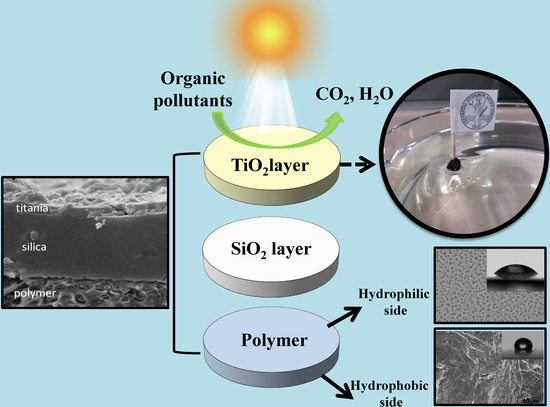
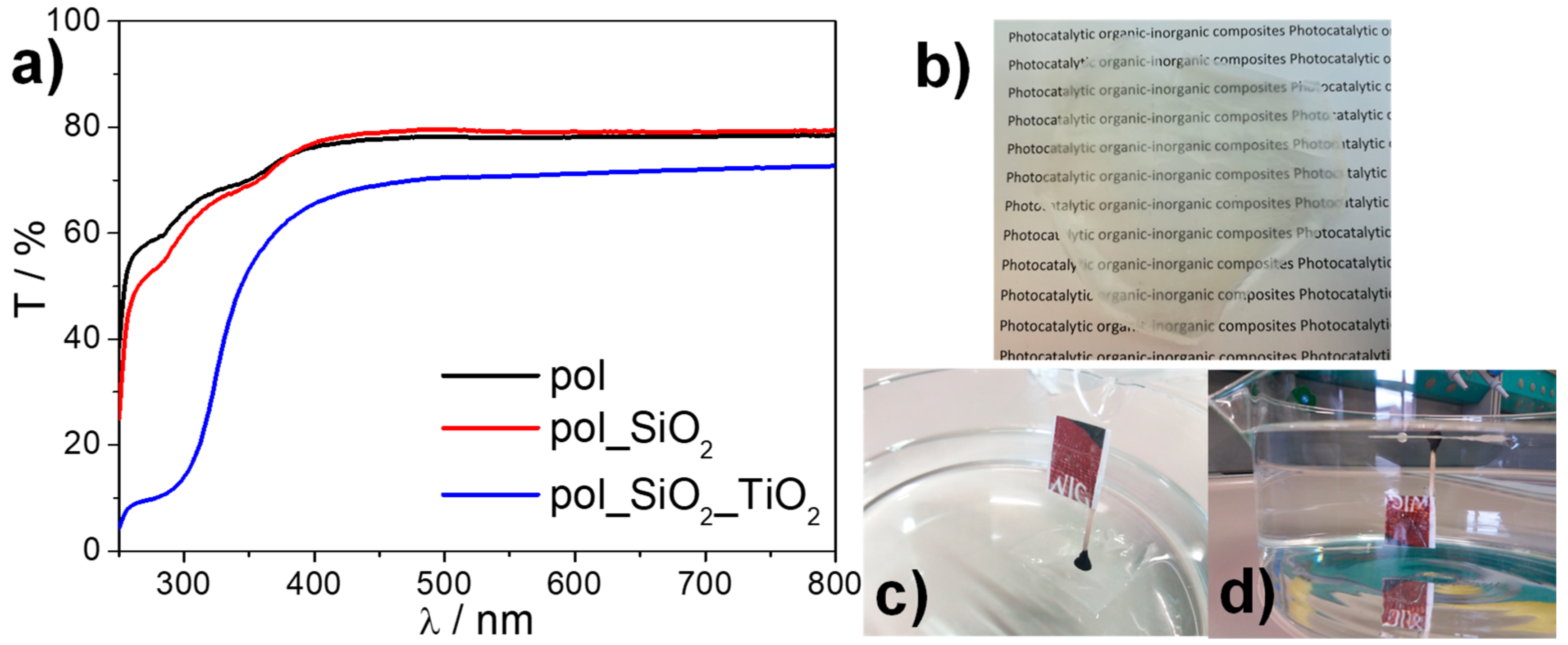
2.2. Device Preparation and Characterization

Figure 2 shows top SEM images of the different components of the photocatalytic device, i.e., of the device layers in each stage of its assembly. The relative water contact angles are also reported in inset. The air side and the mould side of the as-deposited polymeric foil present notable differences both in terms of wetting and morphological features (Figure 2a,b). While the air side (Figure 2a) appears highly homogeneous and smooth, the mould side (Figure 2b) is characterized by micrometric roughness due to Teflon mould adopted for the deposition. The two sides of the as-deposited polymer foil show different wettability thanks to the orientation of the fluorinated chains of POMA towards the Teflon mould side. The corona treatment increases the hydrophilicity of the polymer surface (reaching a value of 44 ± 1° right after the treatment) surface and imparts a morphological change in the polymer foils (Figure 2c). Micrometric cavities can be detected, in agreement with the literature [33], which are excavated by the energy particles bombardment. These micro pits concur to improve the adhesion of the inorganic layers due to a larger potential bond area [33]. The silica layer spray-deposited onto the polymer surface is crack-free and homogeneously covers the whole foil surface (Figure 2d) and further increases the hydrophilicity of the surface (32 ± 6°). Upon deposition of the TiO2 layer, the presence of titania particles leads to an appreciable surface roughness (Figure 2e) and to a slight increase of the water contact angle (63 ± 2°) for the unirradiated sample. Even after prolonged irradiation in water, the morphology of the film remains comparable with the one of a pristine sample (Figure 2f).
Cross-sectional SEM images of the bare polymer foil and of the final composite device are reported in Figure 3. Figure 3a shows that the polymer foil has a porous morphology, induced by the choice of the casting solvent, which is at the basis of the lightness of the foil and enhances its floating capabilities. The thickness of the foil was measured to be ca. 200 μm. Figure 3b shows instead the thickness and the morphology of the inorganic layers (SiO2 and TiO2) deposited onto the polymer substrate in the complete device. A micrometric silica layer with a very compact morphology favors the protection the organic substrate from the photocatalytically produced radical species. The top titania layer is instead much thinner, in agreement with previous reports [34]; moreover, the active TiO2 layer displays a rough and porous morphology, as also shown by the top view micrographs, which can be beneficial for the photocatalytic application by enhancing the actual surface area extension and by increasing photon absorption [35].
XRD patterns of the complete device collected on a Philips PW 3710 Bragg-Brentano goniometer proved unsuccessful in determining the structural composition of the TiO2 top layer, due to the limited thickness of the film. However, the phase composition of the top layer can be inferred from its synthetic procedure: The addition of Hombikat UV 100 ensures the presence of crystalline anatase particles (see Section 3.2.4). Besides the crystalline commercial particles, the TiO2 film is expected to show limited crystallinity due to the lack of high temperature post-treatments needed to promote the formation of crystalline anatase [34].
The transmittance spectra of the device before and after the deposition of the TiO2 layer are reported in Figure 4a together with the spectrum of the bare polymer, for the sake of comparison. The bare polymer foil presents high transparency in the whole visible range (constant transmittance of ca. 80% between 400 and 800 nm). This is a highly desirable feature for application in natural settings as water basins. In the UV region, the transmittance shows a good degree of transparency, presenting a transmittance >60% up to 285 nm, enabling an efficient use of sunlight by the TiO2 layer in the full device even when the device is capsized. The deposition of the silica layer leads to a further slight enhancement of transmittance in the visible range, owing to the antireflective properties of the silica film [36], while in the UV region a minor decrease of transmittance is observed, due to the characteristic light absorption of SiO2, remaining however >55% up to 285 nm. The complete photocatalytic device still presents a good transparency (transmittance ca. 70%) in the whole visible region, as also revealed by the photograph reported in Figure 4b. In the UV region, the characteristic absorption of TiO2 is appreciable, due to the top titania layer. It should be noted that up to 340 nm the device shows substantial transparency (transmittance > 50%), which guarantees the photoactivation of the titania layer also with back illumination. The device can thus be used for both the degradation of water pollutants and gaseous organic compounds present in the atmosphere. In fact, as appreciable from Figure 4c,d, the device revealed high floating capabilities, which remained stable in time, owing to the lightness of the polymer, together with the enhanced hydrophobicity of the bottom side provided by the use of the fluorinated comonomer.

2.3. Photocatalytic Activity

The photocatalytic activity of the device was firstly tested in the gas phase degradation of VOCs. In this respect, ethanol was selected as model molecule on the grounds of a previous work [37]. The present device proved to be effective in the degradation of ethanol vapor, achieving complete disappearance of the target molecule after 4 h of irradiation (Figure S5) despite the high pollutant concentration (200 ppm) and the low irradiated TiO2 amount (ca. 9 mg). Moreover, the main intermediate (acetaldehyde) was almost entirely removed after 6 h, leading to CO2 and water as final products (Figure S5). Photolysis tests performed in the same conditions but without the device, showed an ethanol disappearance rate of 1.2 × 10⁻³ min−1 and no appreciable formation of intermediates/CO2.
The present result is thus comparable with previous reports of ethanol gas phase degradation using a similar amount of P25 free powder [38]. However, with respect to previous reports showing substantial deactivation just upon three recycle tests [38], in the present case the device maintained its photocatalytic activity after three consecutive photocatalytic runs (Figure 5a), as appreciable from the pollutant pseudo-first order disappearance rates. In all cases, the mineralization (complete oxidation to CO2) was larger than 75%, proving the stability and the reusability of the prepared photocatalytic device.
The photocatalytic activity of the device was also evaluated towards the degradation of tetracycline. Tetracyclines are the best-selling antibiotics [39] and have been classified as emerging pollutants [40,41]. Due to their large usage in both humans and animals, tetracyclines are among the most frequently detected micropollutants both in wastewaters [42] and in large water basins as the lakes of Northern Italy [43], leading to increased levels of tetracycline-resistant bacteria [44]. Under simulated solar light with back irradiation, the floating device achieved a tetracycline degradation of 50% after 14 h of irradiation, without any decrease of the performance during the reaction time (Figure 5b), suggesting the possibility to completely degrade the target molecule by prolonging the irradiation. A pseudo-first order kinetics of 4.7 ± 0.1 h−1 was observed (Figure 5b). Tests performed in the same conditions in the absence of the device showed a photolysis rate of 1.3 ± 0.1 h−1, in agreement with previous reports [45].
Only few studies reported the photocatalytic degradation of pollutants by floating devices under solar light [21]. Although comparisons are difficult to draw due to the different experimental conditions, the presently reported floating device shows promising performance with respect to previous reports as several literature studies obtain similar degradation rates using much larger TiO2 actual contents [20,46,47].
The stability of the device after prolonged UV irradiation in working conditions is also testified by cross-sectional SEM images (Figure S6). The rough morphology of the top TiO2 layer is well appreciable as well as the compact silica layer. It should be noted that the overall thickness of the oxide layer can vary due to the adopted deposition procedure (spray coating).

3. Materials and Methods

3.1. Materials

Methyl methacrylate (MMA, 99%), methacryloyl chloride (97%), 1H,1H,2H,2H-Perfluoro-1-octanol (97%), α,α’-Azoisobutyronitrile (AIBN, 99%), triethyl amine (TEA, ≥99.9%), sodium bicarbonate (NaHCO3, ≥99.7%), sodium sulfate (Na2SO4, ≥99.99%), cyclohexane (99.5% anhydrous), methanol (99.8% anhydrous), α-methylstyrene (≥99% anhydrous), distilled water Chromasolv® (≥99.9%), methylene chloride (CH2Cl2, ≥99.8% anhydrous), hydrochloric acid (HCl, 37%), tetrahydrofuran (THF, ≥99.8% anhydrous) and chloroform-d (CDCl3, 99.96 atom % D) were acquired from Sigma-Aldrich (St. Louis, MI, USA)and used without further purification. Doubly distilled water passed through a Milli-Q apparatus (Sigma-Aldrich, St. Louis, MI, USA) was adopted to prepare solutions and suspensions.

3.2. Preparation Procedures

3.2.1. Synthesis of POMA

The reaction was carried out under inert atmosphere using a 100 mL three-neck round bottom flask equipped with a nitrogen inlet adapter, an internal thermometer adapter, an overhead magnetic stirrer and a reflux condenser. Firstly, 20 mL of methylene chloride, methacryloyl chloride (2.8 g) and 1H,1H,2H,2H-Perfluoro-1-octanol (9.8 g) were mixed. Then, 2.9 g of TEA was added to neutralize HCl formed during the esterification reaction. The solution was carefully cooled down to 0 °C and then stirred for 16 h. Afterwards, it was gradually brought back to room temperature. The solution was washed several times with an aqueous solution of HCl at 5% w/w and then with NaHCO3 5% w/w to remove traces of TEA and HCl, respectively. Water traces were removed with Na2SO4 and the salt was removed via filtration. The resulting solution was dried under vacuum (ca. 4 mbar) at 40 °C for 1 h (96% yield). The structure of POMA was confirmed via 1H NMR spectroscopy (Figure S1).

3.2.2. Synthesis of MMA_α-Methylstyrene_POMA Ter-Polymer

The reaction was performed under inert atmosphere in a 100 mL two-necked round bottom flask equipped with a nitrogen inlet adapter, a reflux condenser and an overhead magnetic stirrer. 40 mL of cyclohexane was mixed with MMA (14.6 g) and α-methylstyrene (4.3 g) POMA (0.8 g) and AIBN (0.3 g), used as free radical initiator. The resulting molar ratios were 8:2 MMA: α-methylstyrene, 1% mol·mol−1 POMA: (MMA and α-methylstyrene), and 1% mol·mol−1 AIBN: (MMA, α-methylstyrene and POMA). The solution heated in an oil bath at 70 °C for 24 h, then gradually cooled down to room temperature. A white solid was precipitated by addition of a large excess of methanol. After recovering the solid by filtration, the polymer was washed with methanol for several days under stirring to remove unreacted methacrylic monomers. After washing, the polymer was dried in a vacuum oven (ca. 4 mbar) at 40 °C for 48 h. The structure of the product was confirmed via 1H NMR spectroscopy (Figure S2).

3.2.3. Silica and Titania Sol Preparation

The silica sol was prepared by a modification of the procedure reported by Soliveri et al. [34]. Firstly, 10 g of tetraethyl orthosilicate (TEOS, Sigma-Aldrich, St. Louis, MI, USA) was added to a solution of 4.5 g of 0.1 M HCl and 25 g of ethanol. The mixture was stirred at room temperature for 120 min and then refluxed at 60 °C for 60 min. After cooling down, a solution prepared by dissolving 2 g of Lutensol ON 70 (BASF, Ludwigshafen, Germany) in 25 g of ethanol (>99.8%, Sigma-Aldrich) was added to the reaction mixture and stirred for 1 h. A stable, transparent sol was obtained.
For the preparation of the titania sol [48], 28.4 g of titanium isopropoxide (97%, Sigma-Aldrich) was dissolved in 79 g of ethanol and 0.9 mL of HCl 37% was added while stirring. Then, a solution of 0.47 g of Lutensol ON 70 in 79 g of ethanol was added. The resulting stable and transparent sol was stirred at 1 h at room temperature.

3.2.4. Device Preparation

Polymer films were prepared via solution casting: 1.8 g of polymer was dissolved in 10 mL of CH2Cl2 and the resulting solution was cast onto a PTFE mould (7 cm in diameter). The films were dried overnight at 25 °C and atmospheric pressure. The air side of the polymer film was corona treated (Aslan Machinery, Germantown, MD, USA; voltage: 0.43 kW; exposition time: 5 min) in order to promote the adhesion of the oxide layers. Then, the SiO2 layer was deposited by spray coating the silica sol (nozzle diameter: 0.5 mm, target-nozzle distance ca. 30 cm; spraying time ca. 1 s, 3 layers). After drying at room temperature, the TiO2 layer was deposited by spray coating a suspension of Hombikat UV100 (Sachtleben Chemie GmbH, Duisburg, Germany) (pure anatase, average crystallite size 10 nm, specific surface area ca. 350 m2 g−1) in the prepared titania sol (2 mg of Hombikat UV100 + 1 mL of ethanol + 0.3 mL titania sol), in the same conditions adopted for the silica layer. The prepared device was immediately dried in oven at 90 °C for 20 h. A further treatment was performed by immersing the device in water for 10 min at 70 °C and finally in 10−4 M HNO3 for 20 min at 70 °C, according to a previously reported procedure [23]. Finally, the device was dried in an oven and irradiated for 3 h under UV light.

3.3. Characterization Methods

Nuclear magnetic resonance spectroscopy (NMR). 1H NMR spectra were collected at 25 °C with a Bruker 400 MHz spectrometer (Bruker, Billerica, MA, USA). The samples for the analyses were prepared dissolving 10–15 mg of POMA/ter-polymer in 1 mL of CDCl3.
Size Exclusion Chromatography (SEC). The polymer molecular weight before and after accelerated ageing was investigated by SEC using a Waters 1515 Isocratic HPLC pump (Waters, Milford, MA, USA) and a four Phenomenex Phenogel (5 × 10⁻³ Å–5 × 10⁻⁴ Å–5 × 10⁻⁵ Å–5 × 500 Å) column set with a RI detector (Waters 2487, Milford, MA, USA) using a flow rate of 1 mL/min and 40 μL as injection volume. Samples were prepared dissolving 40 mg of polymer in 1 mL of anhydrous THF; before the analysis, the solution was filtered with 0.45 μm filters. Molecular weight data were expressed in polystyrene (PS) equivalents. The calibration was built using monodispersed PS standards having the following nominal peak molecular weight (Mp) and molecular weight distribution (D): Mp = 1,600,000 Da (D ≤ 1.13), Mp = 1,150,000 Da (D ≤ 1.09), Mp = 900,000 Da (D ≤ 1.06), Mp = 400,000 Da (D ≤ 1.06), Mp = 200,000 Da (D ≤ 1.05), Mp =90,000 Da (D ≤ 1.04), Mp = 50,400 Da (D = 1.03), Mp = 30,000 Da (D = 1.06), Mp = 17,800 Da (D = 1.03), Mp = 9730 Da (D = 1.03), Mp = 5460 Da (D = 1.03), Mp = 2032 Da (D = 1.06), Mp = 1241 Da (D = 1.07), Mp = 906 Da (D = 1.12), Mp = 478 Da (D = 1.22); Ethyl benzene (molecular weight = 106 g/mol). For all analyses, 1,2-dichlorobenzene was used as internal reference. The molecular weights of the samples obtained after the UV exposure test were also determined.
Differential Scanning Calorimetry (DSC). The polymer glass transition temperature (Tg) was measured by DSC analyses on a Mettler Toledo DSC1 (Zurich, Switzerland), using a 10 °C/min heating rate and under nitrogen atmosphere. Before measurement, samples were heated at 90 °C to eliminate residual internal stresses from the synthesis.
Fourier Transform Infrared Spectroscopy (FT-IR). FT-IR spectra were collected on a Spectrum 100 spectrophotometer (Perkin Elmer, Waltham, MA, USA) working in attenuated total reflection (ATR) mode. A single-bounce diamond crystal was used with an incidence angle of 45°.
Water Contact Angle (WCA) analyses. Water contact angle measurements were carried out using a Krüss EasyDrop (Krüss, Hamburg, Germany), on at least ten independent measurements using 5 µL water droplets.
UV-vis spectroscopy. UV-vis transmittance spectra were acquired in the 250–800 nm range by using a Shimadzu UV2600 spectrophotometer (Tokyo, Japan).
Scanning electron microscopy (SEM). Top and cross-sectional SEM images were collected on a Zeiss LEO-1430 (Oberkochern, Germany). Samples were sputter coated with Au before measurements.
Mechanical properties. The polymer sample preparation and the determination of their elastic modulus, tensile strength and elongation at break were performed in agreement with the ISO 527-1/2 standard method using a Kistler 9273 dynamometer (Winterthur, Switzerland).
Permeability test. The permeability test was conducted in oxygen atmosphere, at 23 °C and with a relative humidity of 40%, in accordance to the ASTM D3985 standard test method for oxygen gas transmission rate through plastic films and sheeting using a colorimetric sensor.
UV stability test. An accelerated aging test was conducted according to the UNI10925:2001 standard method to evaluate the stability under UV radiation of the prepared polymer foils. The test was conducted for 100 h (T = 25 °C and p = 1 atm), with a Jelosil HG500 lamp (Milan, Italy; 45 mW cm−2 in the 280–400 nm range).

3.4. Photocatalytic Activity

The photocatalytic activity of the device was tested under both UV (Jelosil HG500, effective power density: 17 mW cm−2 in the 280–400 nm) and simulated solar irradiation (UltraVitalux lamp, Osram, Munich, Germany, effective power density: 4.5 mW cm−2 in the 280–400 nm range and 14 mW cm−2 in the 400–800 nm range).
Tests were carried out both in the gas phase and in water. The gas phase degradation of ethanol was carried out using a previously reported setup [37]. An active surface area of 38 cm2 and an initial pollutant concentration of 198 ppm were employed; a gas chromatographic system was adopted for monitoring the pollutant disappearance, and the formation of acetaldehyde (main reaction intermediate) and CO2 (complete degradation product). Three consecutive photocatalytic tests were performed in the same conditions to test the stability and the reusability of the device. The degradation of a tetracycline hydrochloride (TC) in water was conducted in an open reactor, with a total active surface of 60 cm2 and an initial pollutant concentration of 12 ppm (V = 300 mL). The reaction was carried out at spontaneous pH and oxygen saturation was maintained via air bubbling. Before irradiation, the device was kept in the dark for 30 min in order to achieve adsorption-desorption equilibrium. The molecule disappearance was monitored by UV-vis spectrophotometry, by recording the intensity of the characteristic absorption peak of tetracycline at 357 nm, in agreement with previous literature reports [41,49,50].

4. Conclusions

In this work, we presented a floating photocatalytic device based on TiO2 photocatalyst immobilized over an ad hoc synthesized ter-polymer. The developed methylmethacrylate, α-methylstyrene and perfluoroctyl methacrylate ter-polymer is characterized by a highly porous morphology and inherent hydrophobicity, which enable a stable buoyancy. Furthermore, the support, displaying the characteristic optical transparency and oxygen permeability of PMMA, was engineered to possess enhanced thermal stability, mechanical resistance and photostability, in order to promote the device durability. The compatibility of the inorganic top coating was enhanced by a series of strategies: (1) an ad hoc polymer casting method leading to reorganization of the hydrophobic chains and dual wetting features of the opposite film sides; (2) the corona treatment of the polymer surface aimed at increasing hydrophilicity and creating surface pitting to bolster adhesion of the inorganic coating; (3) the deposition of an intermediate SiO2 layer, which improves the adhesion of the TiO2 top layer and protects the polymer support from the radical species generated by photocatalytic oxidation. The adopted TiO2 layer contains commercial nanoparticles with high photocatalytic activity bound together by a titania sol promoting adhesion. The final device showed promising results in photocatalytic degradation tests of both water and gas phase pollutants, also in recycle tests. Tests were carried out under both UV and simulated solar irradiation, with either front or back irradiation, confirming the ability of the device to work also when capsized. Future work will further optimize the TiO2 amount to boost the photocatalytic activity of the device by both increasing the nanoparticles content in the top layer and using fibers and sponge architectures as an alternative to polymer films.

Supplementary Materials

The following are available online at https://www.mdpi.com/2073-4344/8/11/568/s1, Figure S1. 1H NMR spectrum of POMA monomer, Figure Figure S2. 1H NMR spectrum of MMA_ α-methylstyrene_POMA polymer, Figure S3. O2 transfer with respect to time of the synthesized MMA_α-methylstyrene_POMA, Figure S4. FT-IR spectra of MMA_α-methylstyrene_POMA collected before and after the UV stability test at the air (i) and PTFE (ii) side, Figure S5. Ethanol disappearance and acetaldehyde and CO2 formation during the photocatalytic test under UV irradiation, Figure S6. Cross-sectional SEM images after UV irradiation for over 15 hours in working conditions.

Author Contributions

Conceptualization, V.S., D.M., S.A.; methodology, L.T., V.S., L.R.; formal analysis and data curation, L.R., V.S., D.M.; writing—original draft preparation, D.M., V.S., L.R.; writing—review and editing, D.M., S.A., V.S., L.R.; resources, M.A.O., H.F., S.A.; supervision, M.A.O., H.F., S.A.

Funding

This research received no external funding.

Acknowledgments

The authors wish to thank Stefano Farris and Riccardo Rampazzo of the Dipartimento di Scienze per gli Alimenti, la Nutrizione e l’Ambiente (Defens) at the Università degli Studi di Milano, for assistance during corona treatment and gas permeability measurements.

Conflicts of Interest

The authors declare no conflict of interest.

References

  1. Crippa, M.; Bianchi, A.; Cristofori, D.; D’Arienzo, M.; Merletti, F.; Morazzoni, F.; Scotti, R.; Simonutti, R. High dielectric constant rutile–polystyrene composite with enhanced percolative threshold. J. Mater. Chem. C 2013, 1, 484–492. [Google Scholar] [CrossRef]
  2. Zhang, S.; Cao, J.; Shang, Y.; Wang, L.; He, X.; Li, J.; Zhao, P.; Wang, Y. Nanocomposite polymer membrane derived from nano TiO2 -PMMA and glass fiber nonwoven: High thermal endurance and cycle stability in lithium ion battery applications. J. Mater. Chem. A 2015, 3, 17697–17703. [Google Scholar] [CrossRef]
  3. Li, W.; Li, H.; Zhang, Y.-M. Preparation and investigation of PVDF/PMMA/TiO2 composite film. J. Mater. Sci. 2009, 44, 2977–2984. [Google Scholar] [CrossRef]
  4. Motaung, T.E.; Luyt, A.S.; Bondioli, F.; Messori, M.; Saladino, M.L.; Spinella, A.; Nasillo, G.; Caponetti, E. PMMA–titania nanocomposites: Properties and thermal degradation behaviour. Polym. Degrad. Stab. 2012, 97, 1325–1333. [Google Scholar] [CrossRef]
  5. Pan, B.; Pan, B.; Zhang, W.; Lv, L.; Zhang, Q.; Zheng, S. Development of polymeric and polymer-based hybrid adsorbents for pollutants removal from waters. Chem. Eng. J. 2009, 151, 19–29. [Google Scholar] [CrossRef]
  6. Wang, M.; Yang, G.; Jin, P.; Tang, H.; Wang, H.; Chen, Y. Highly hydrophilic poly(vinylidene fluoride)/meso-titania hybrid mesoporous membrane for photocatalytic membrane reactor in water. Sci. Rep. 2016, 6, 19148. [Google Scholar] [CrossRef] [PubMed] [Green Version]
  7. Díez-Pascual, A.M.; Díez-Vicente, A.L. Nano-TiO2 Reinforced PEEK/PEI Blends as Biomaterials for Load-Bearing Implant Applications. ACS Appl. Mater. Interfaces 2015, 7, 5561–5573. [Google Scholar] [CrossRef] [PubMed]
  8. Salabat, A.; Mirhoseini, F. Applications of a new type of poly(methyl methacrylate)/TiO2 nanocomposite as an antibacterial agent and a reducing photocatalyst. Photochem. Photobiol. Sci. 2015, 14, 1637–1643. [Google Scholar] [CrossRef] [PubMed]
  9. Ravirajan, P.; Haque, S.A.; Durrant, J.R.; Bradley, D.D.C.; Nelson, J. The Effect of Polymer Optoelectronic Properties on the Performance of Multilayer Hybrid Polymer/TiO2 Solar Cells. Adv. Funct. Mater. 2005, 15, 609–618. [Google Scholar] [CrossRef]
  10. Lee, H.J.; Leventis, H.C.; Haque, S.A.; Torres, T.; Grätzel, M.; Nazeeruddin, M.K. Panchromatic response composed of hybrid visible-light absorbing polymers and near-IR absorbing dyes for nanocrystalline TiO2-based solid-state solar cells. J. Power Sources 2011, 196, 596–599. [Google Scholar] [CrossRef]
  11. Wen, R.; Guo, J.; Zhao, C.; Liu, Y. Nanocomposite Capacitors with Significantly Enhanced Energy Density and Breakdown Strength Utilizing a Small Loading of Monolayer Titania. Adv. Mater. Interfaces 2018, 5, 1701088. [Google Scholar] [CrossRef]
  12. Cao, J.; Wang, L.; He, X.; Fang, M.; Gao, J.; Li, J.; Deng, L.; Chen, H.; Tian, G.; Wang, J.; et al. In situ prepared nano-crystalline TiO2–poly(methyl methacrylate) hybrid enhanced composite polymer electrolyte for Li-ion batteries. J. Mater. Chem. A 2013, 1, 5955–5961. [Google Scholar] [CrossRef]
  13. Chen, Y.-H.; Liu, Y.-Y.; Lin, R.-H.; Yen, F.-S. Photocatalytic degradation of p-phenylenediamine with TiO2-coated magnetic PMMA microspheres in an aqueous solution. J. Hazard. Mater. 2009, 163, 973–981. [Google Scholar] [CrossRef] [PubMed]
  14. Chen, Y.-H.; Chen, L.-L.; Shang, N.-C. Photocatalytic degradation of dimethyl phthalate in an aqueous solution with Pt-doped TiO2-coated magnetic PMMA microspheres. J. Hazard. Mater. 2009, 172, 20–29. [Google Scholar] [CrossRef] [PubMed]
  15. Xu, Y.; Wen, W.; Wu, J.-M. Titania nanowires functionalized polyester fabrics with enhanced photocatalytic and antibacterial performances. J. Hazard. Mater. 2018, 343, 285–297. [Google Scholar] [CrossRef] [PubMed]
  16. Zhou, X.; Shao, C.; Yang, S.; Li, X.; Guo, X.; Wang, X.; Li, X.; Liu, Y. Heterojunction of g-C3N4/BiOI Immobilized on Flexible Electrospun Polyacrylonitrile Nanofibers: Facile Preparation and Enhanced Visible Photocatalytic Activity for Floating Photocatalysis. ACS Sustain. Chem. Eng. 2018, 6, 2316–2323. [Google Scholar] [CrossRef]
  17. Krýsa, J.; Waldner, G.; Měšt’ánková, H.; Jirkovský, J.; Grabner, G. Photocatalytic degradation of model organic pollutants on an immobilized particulate TiO2 layer. Appl. Catal. B Environ. 2006, 64, 290–301. [Google Scholar] [CrossRef]
  18. Tu, W.; Lin, Y.-P.; Bai, R. Enhanced performance in phenol removal from aqueous solutions by a buoyant composite photocatalyst prepared with a two-layered configuration on polypropylene substrate. J. Environ. Chem. Eng. 2016, 4, 230–239. [Google Scholar] [CrossRef]
  19. Ni, L.; Li, Y.; Zhang, C.; Li, L.; Zhang, W.; Wang, D. Novel floating photocatalysts based on polyurethane composite foams modified with silver/titanium dioxide/graphene ternary nanoparticles for the visible-light-mediated remediation of diesel-polluted surface water. J. Appl. Polym. Sci. 2016, 133. [Google Scholar] [CrossRef]
  20. Han, H.; Bai, R. Highly effective buoyant photocatalyst prepared with a novel layered-TiO2 configuration on polypropylene fabric and the degradation performance for methyl orange dye under UV–Vis and Vis lights. Sep. Purif. Technol. 2010, 73, 142–150. [Google Scholar] [CrossRef]
  21. Xing, Z.; Zhang, J.; Cui, J.; Yin, J.; Zhao, T.; Kuang, J.; Xiu, Z.; Wan, N.; Zhou, W. Recent advances in floating TiO2-based photocatalysts for environmental application. Appl. Catal. B Environ. 2018, 225, 452–467. [Google Scholar] [CrossRef]
  22. Yang, M.; Di, Z.; Lee, J.-K. Facile control of surface wettability in TiO2/poly(methyl methacrylate) composite films. J. Colloid Interface Sci. 2012, 368, 603–607. [Google Scholar] [CrossRef] [PubMed]
  23. Soliveri, G.; Sabatini, V.; Farina, H.; Ortenzi, M.A.; Meroni, D.; Colombo, A. Double side self-cleaning polymeric materials: The hydrophobic and photoactive approach. Colloids Surf. A Physicochem. Eng. Asp. 2015, 483, 285–291. [Google Scholar] [CrossRef]
  24. Ma, J.Z.; Hu, J.; Zhang, Z.J. Polyacrylate/silica nanocomposite materials prepared by sol-gel process. Eur. Polym. J. 2007, 43, 4169–4177. [Google Scholar] [CrossRef]
  25. McLaren, A.C.; McLaren, S.G.; Hickmon, M.K. Sucrose, xylitol, and erythritol increase PMMA permeability for depot antibiotics. Clin. Orthop. Relat. Res. 2007, 461, 60–63. [Google Scholar] [CrossRef] [PubMed]
  26. Sabatini, V.; Farina, H.; Montarsolo, A.; Ardizzone, S.; Ortenzi, M.A. Novel Synthetic Approach to Tune the Surface Properties of Polymeric Films: Ionic Exchange Reaction between Sulfonated Polyarylethersulfones and Ionic Liquids. Polym. Plast. Technol. Eng. 2017, 56, 296–309. [Google Scholar] [CrossRef]
  27. Sabatini, V.; Cattò, C.; Cappelletti, G.; Cappitelli, F.; Antenucci, S.; Farina, H.; Ortenzi, M.A.; Camazzola, S.; Di Silvestro, G. Protective features, durability and biodegration study of acrylic and methacrylic fluorinated polymer coatings for marble protection. Prog. Org. Coat. 2018, 114, 47–57. [Google Scholar] [CrossRef]
  28. Cappelletti, G.; Ardizzone, S.; Meroni, D.; Soliveri, G.; Ceotto, M.; Biaggi, C.; Benaglia, M.; Raimondi, L. Wettability of bare and fluorinated silanes: A combined approach based on surface free energy evaluations and dipole moment calculations. J. Colloid Interface Sci. 2013, 389, 284–291. [Google Scholar] [CrossRef] [PubMed]
  29. Huang, W.; Kim, J.-B.; Bruening, M.L.; Baker, G.L. Functionalization of Surfaces by Water-Accelerated Atom-Transfer Radical Polymerization of Hydroxyethyl Methacrylate and Subsequent Derivatization. Macromolecules 2002, 35, 1175–1179. [Google Scholar] [CrossRef]
  30. Chiantore, O.; Trossarelli, L.; Lazzari, M. Photooxidative degradation of acrylic and methacrylic polymers. Polymer 2000, 41, 1657–1668. [Google Scholar] [CrossRef]
  31. McNeill, I.C.; Sadeghi, S.M.T. Thermal stability and degradation mechanisms of poly(acrylic acid) and its salts: Part 1—Poly(acrylic acid). Polym. Degrad. Stab. 1990, 29, 233–246. [Google Scholar] [CrossRef]
  32. Zuev, V.V.; Bertini, F.; Audisio, G. Investigation on the thermal degradation of acrylic polymers with fluorinated side-chains. Polym. Degrad. Stab. 2006, 91, 512–516. [Google Scholar] [CrossRef]
  33. Carradò, A.; Sokolova, O.; Donnio, B.; Palkowski, H. Influence of corona treatment on adhesion and mechanical properties in metal/polymer/metal systems. J. Appl. Polym. Sci. 2011, 120, 3709–3715. [Google Scholar] [CrossRef]
  34. Soliveri, G.; Pifferi, V.; Panzarasa, G.; Ardizzone, S.; Cappelletti, G.; Meroni, D.; Sparnacci, K.; Falciola, L. Self-cleaning properties in engineered sensors for dopamine electroanalytical detection. Analyst 2015, 140, 1486–1494. [Google Scholar] [CrossRef] [PubMed]
  35. Arabatzis, I.; Antonaraki, S.; Stergiopoulos, T.; Hiskia, A.; Papaconstantinou, E.; Bernard, M.; Falaras, P. Preparation, characterization and photocatalytic activity of nanocrystalline thin film TiO2 catalysts towards 3,5-dichlorophenol degradation. J. Photochem. Photobiol. A Chem. 2002, 149, 237–245. [Google Scholar] [CrossRef]
  36. Pifferi, V.; Rimoldi, L.; Meroni, D.; Segrado, F.; Soliveri, G.; Ardizzone, S.; Falciola, L. Electrochemical characterization of insulating silica-modified electrodes: Transport properties and physicochemical features. Electrochem. Commun. 2017, 81, 102–105. [Google Scholar] [CrossRef]
  37. Antonello, A.; Soliveri, G.; Meroni, D.; Cappelletti, G.; Ardizzone, S. Photocatalytic remediation of indoor pollution by transparent TiO2 films. Catal. Today 2014, 230, 35–40. [Google Scholar] [CrossRef]
  38. Piera, E.; Ayllón, J.A.; Doménech, X.; Peral, J. TiO2 deactivation during gas-phase photocatalytic oxidation of ethanol. Catal. Today 2002, 76, 259–270. [Google Scholar] [CrossRef]
  39. U.S. Food and Drug Administration. Summary Report on Antimicrobials Sold or Distributed for Use in Food-Producing Animals; U.S. Food and Drug Administration: Washington, DC, USA, 2016. [Google Scholar]
  40. Rimoldi, L.; Pargoletti, E.; Meroni, D.; Falletta, E.; Cerrato, G.; Turco, F.; Cappelletti, G. Concurrent role of metal (Sn, Zn) and N species in enhancing the photocatalytic activity of TiO2 under solar light. Catal. Today 2018, 313, 40–46. [Google Scholar] [CrossRef]
  41. Palominos, R.A.; Mondaca, M.A.; Giraldo, A.; Peñuela, G.; Pérez-Moya, M.; Mansilla, H.D. Photocatalytic oxidation of the antibiotic tetracycline on TiO2 and ZnO suspensions. Catal. Today 2009, 144, 100–105. [Google Scholar] [CrossRef]
  42. Wei, R.; Ge, F.; Huang, S.; Chen, M.; Wang, R. Occurrence of veterinary antibiotics in animal wastewater and surface water around farms in Jiangsu Province, China. Chemosphere 2011, 82, 1408–1414. [Google Scholar] [CrossRef] [PubMed]
  43. Calamari, D.; Zuccato, E.; Castiglioni, S.; Bagnati, R.; Fanelli, R. Strategic Survey of Therapeutic Drugs in the Rivers Po and Lambro in Northern Italy. Environ. Sci. Technol. 2003, 37, 1241–1248. [Google Scholar] [CrossRef]
  44. Czekalski, N.; Berthold, T.; Caucci, S.; Egli, A.; Bürgmann, H. Increased Levels of Multiresistant Bacteria and Resistance Genes after Wastewater Treatment and Their Dissemination into Lake Geneva, Switzerland. Front. Microbiol. 2012, 3, 1–18. [Google Scholar] [CrossRef] [PubMed]
  45. Addamo, M.; Augugliaro, V.; Di Paola, A.; García-López, E.; Loddo, V.; Marcì, G.; Palmisano, L. Removal of drugs in aqueous systems by photoassisted degradation. J. Appl. Electrochem. 2005, 35, 765–774. [Google Scholar] [CrossRef]
  46. Magalhães, F.; Lago, R.M. Floating photocatalysts based on TiO2 grafted on expanded polystyrene beads for the solar degradation of dyes. Sol. Energy 2009, 83, 1521–1526. [Google Scholar] [CrossRef]
  47. Magalhães, F.; Moura, F.C.C.; Lago, R.M. TiO2/LDPE composites: A new floating photocatalyst for solar degradation of organic contaminants. Desalination 2011, 276, 266–271. [Google Scholar] [CrossRef]
  48. Maino, G.; Meroni, D.; Pifferi, V.; Falciola, L.; Soliveri, G.; Cappelletti, G.; Ardizzone, S. Electrochemically assisted deposition of transparent, mechanically robust TiO2 films for advanced applications. J. Nanopart. Res. 2013, 15, 2087. [Google Scholar] [CrossRef]
  49. Rimoldi, L.; Meroni, D.; Cappelletti, G.; Ardizzone, S. Green and low cost tetracycline degradation processes by nanometric and immobilized TiO2 systems. Catal. Today 2017, 281, 38–44. [Google Scholar] [CrossRef]
  50. Reyes, C.; Fernández, J.; Freer, J.; Mondaca, M.A.; Zaror, C.; Malato, S.; Mansilla, H.D. Degradation and inactivation of tetracycline by TiO2 photocatalysis. J. Photochem. Photobiol. A Chem. 2006, 184, 141–146. [Google Scholar] [CrossRef]
Figure 1. Synthetic route for MMA_α-methylstyrene_POMA ter-polymer.
Catalysts 08 00568 g001
Figure 2. SEM images of the air side (a) and the mould side (b) of the polymer foil, of the air side after corona treatment (c), of the silica layer (d) and of the final device before (e) and after (f) prolonged irradiation under working conditions, together with the relative water contact angles (in insets).
Catalysts 08 00568 g002
Figure 3. Cross-sectional SEM images of the deposited polymeric foil (a) and of the final device (b).
Catalysts 08 00568 g003
Figure 4. UV-vis transmittance spectra (a) and photographs proving the transparency (b) and the buoyancy of the composite device on both the mould (c) and air sides (d); a flag was attached on top of the air side of the transparent device to make it more easily detectable.
Catalysts 08 00568 g004
Figure 5. Photocatalytic tests results: (a) ethanol disappearance under UV irradiation and the relative rate constant in the recycle tests; (b) Determination of the rate constant of tetracycline disappearance in simulated solar photocatalytic tests: logarithmic conversion plot as a function of irradiation time (R2 = 0.995).
Catalysts 08 00568 g005
Table 1. Main physicochemical (glass transition temperature, Tg; number average molecular weight, M n ¯ ; molecular weight distribution, D; water contact angles, wCA) and mechanical properties (elastic Young’s tensile modulus, tensile strength, elongation at break) of the MMA_α-methylstyrene_POMA ter-polymer before and after the UV stability test.
Tg (°C) M n ¯ ( Da ) DwCA Air-Side (°)wCA Mould-Side (°)Elastic Modulus (GPa)Tensile Strength (Mpa)Elongation at Break (%)
before UV test123.9281002.167 ± 2114 ± 33.1702.3
after UV test124.0280002.166 ± 3116 ± 22.9681.9

