Article

Highly Efficient and Visible Light Responsive Heterojunction Composites as Dual Photoelectrodes for Photocatalytic Fuel Cell

1
Environmental Science Research Institute, Huazhong University of Science and Technology, Wuhan 430074, China
2
Department of Chemistry, PSG College of Technology, Peelamedu, Coimbatore 641004, India
*
Author to whom correspondence should be addressed.
Catalysts 2018, 8(1), 30; https://doi.org/10.3390/catal8010030
Submission received: 11 November 2017 / Revised: 18 December 2017 / Accepted: 8 January 2018 / Published: 18 January 2018
(This article belongs to the Special Issue Photocatalysts for Organics Degradation)

Abstract

:
In the present work, a novel photocatalytic fuel cell (PFC) system involving a dual heterojunction photoelectrodes, viz. polyaniline/TiO2 nanotubes (PANI/TiO2 NTs) photoanode and CuO/Co3O4 nanorods (CuO/Co3O4 NRs) photocathode, has been designed. Compared to TiO2 NTs electrode of PFC, the present heterojunction design not only enhances the visible light absorption but also offers the higher efficiency in degrading Rhodamine B–a model organic pollutant. The study includes an evaluation of the dual performance of the photoelectrodes as well. Under visible-light irradiation of 3 mW cm−2, the cell composed of the photoanode PANI/TiO2 NTs and CuO/Co3O4 NRs photocathode forms an interior bias of +0.24 V within the PFC system. This interior bias facilitated the transfer of electrons from the photoanode to photocathode across the external circuit and combined with the holes generated therein along with a simultaneous power production. In this manner, the separation of electron/hole pair was achieved in the photoelectrodes by releasing the holes and electrons of PANI/TiO2 NTs photoanode and CuO/Co3O4 NRs photocathode, respectively. Using this PFC system, the degradation of Rhodamine B in aqueous media was achieved to an extent of 68.5% within a reaction duration of a four-hour period besides a simultaneous power generation of 85 μA cm−2.

1. Introduction

Water pollution, a serious issue of global concern, is no doubt a grave threat to human health and societal progress. The contamination of natural water systems is mainly due to lack of effective and viable techniques and excessive discharge of wastewater containing toxic organic contaminants. Developing an effective purification technique to maintain a green ecological environment and simultaneously recover the chemical energy stored abundantly in toxic organics that usually let out as wastewater has become an urgent need of the hour [1,2,3]. A novel device, the so-called photocatalytic fuel cell (PFC), constituted with a photoanode and a photocathode, for wastewater treatment along with simultaneous electricity generation under solar irradiation, is an emerging and attractive technique in the energy and environmental domain [4,5,6]. In this system, the electron/hole pairs can be generated from the photoelectrodes under light irradiation in a defined wavelength region. The electrons produced from the photoanode leave the holes and transfer through the external circuit to the photocathode, and the holes at the photoanode are released for degradation of organic compounds [7]. In addition, the PFC system, in which an n-type semiconductor generally used as photoanode with a Fermi level higher than that of the cathode, could develop interior bias which facilitates the transfer of electrons from photoanode to photocathode thereby producing a concurrent generation of electricity [8]. The existing PFC systems constituting TiO2 and Pt as photoelectrodes [3,8] have severe limitations because TiO2 responds most to ultraviolet (UV) region light and suffers from the high probability of electron/hole pair recombination [9]. Using Pt as photocathode is obviously not a viable approach, which would eventually restrict its application to a large-scale level [10].
To overcome the above mentioned drawbacks, the studies on either developing visible light responsive photoanodes [11,12,13,14] or replacing Pt by p-type semiconductor as the photocathode [15,16] become equally important, leading to the development of dual photoelectrodes for PFC system. However, so far, these PFCs have been identified with its shortcomings that the photoactivity and photostability of the electrodes are poor, which limits their application. For instance, the visible-light driven PFC system using CdS/TiO2 or WO3/W as photoanode and Cu2O/Cu as photocathode suffers from poor stability of the CdS, WO3 and Cu2O due to their photocorrosion nature in aqueous media [17]. The limited usage of these electrodes could be attributed largely to the inherent drawbacks of the material that result in poor response in visible-light region, weak stability and undesirable photoactivity, which eventually limit the performance of the PFC system.
Forming a heterojunction by two different semconductors is an effective strategy to facilitate the hole/electron seperation and enhance the photocatalytic activity [18,19]. For instance, polyaniline (PANI), a conducting polymer, might be a good choice for TiO2 sensitization [20] due to high absorption coefficients in the visible-light region, high mobility of charge carriers and good environmental stability. PANI/TiO2 nanocomposite could be obtained by mixing commercial TiO2 nanopowder with PANI by a chemical oxidative polymerization step [20,21]. On the other hand, oxides of copper and cobalt, which are well known for their p-type semiconducting behavior, could be used as photocathode [22,23,24] replacing the noble metals and also as photocatalysts for degradation of pollutants [25]. These materials can withstand in the multiple processing steps and have a compatibility nature with other material systems. All these notable characteristics behavior make them attractive and interesting base materials for heterostructures. Chopra et al. [25,26] recently established a fact that CuO nanowire−Co3O4 nanoparticle heterostructure has shown a unique photoactivity under visible-light irradiation. The p–p junctions formed by the combination of CuO and Co3O4 could efficiently reduce the probability of recombination of photogenerated electron/hole pairs, which in turn enhances the photocatalytic activity.
In this work, a pair of materials, viz. PANI/TiO2 nanotubes (NTs) as photoanode and CuO/Co3O4 nanoparticles (NRs) as photocathode fabricated based on Ti substrate, was proposed as a novel PFC system, which exhibits an effective degradation behavior toward Rhodamine B and shows an efficient generation of electricity.

2. Results and Discussion

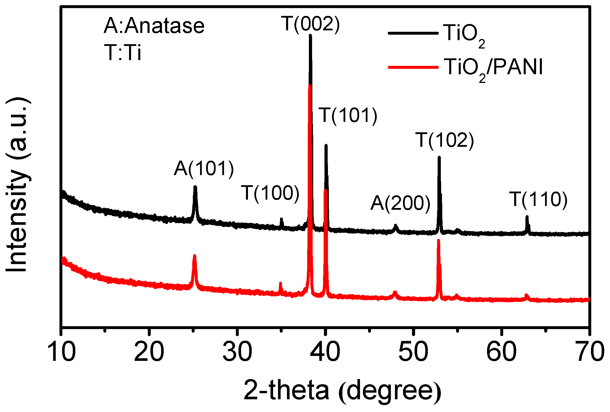
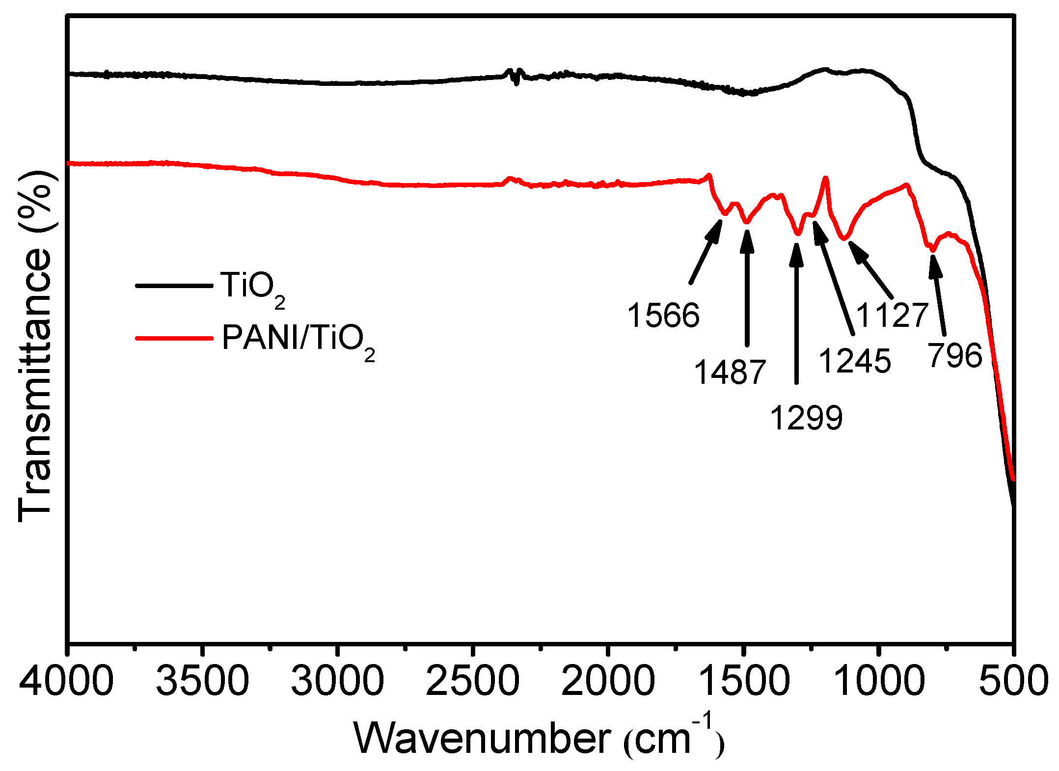
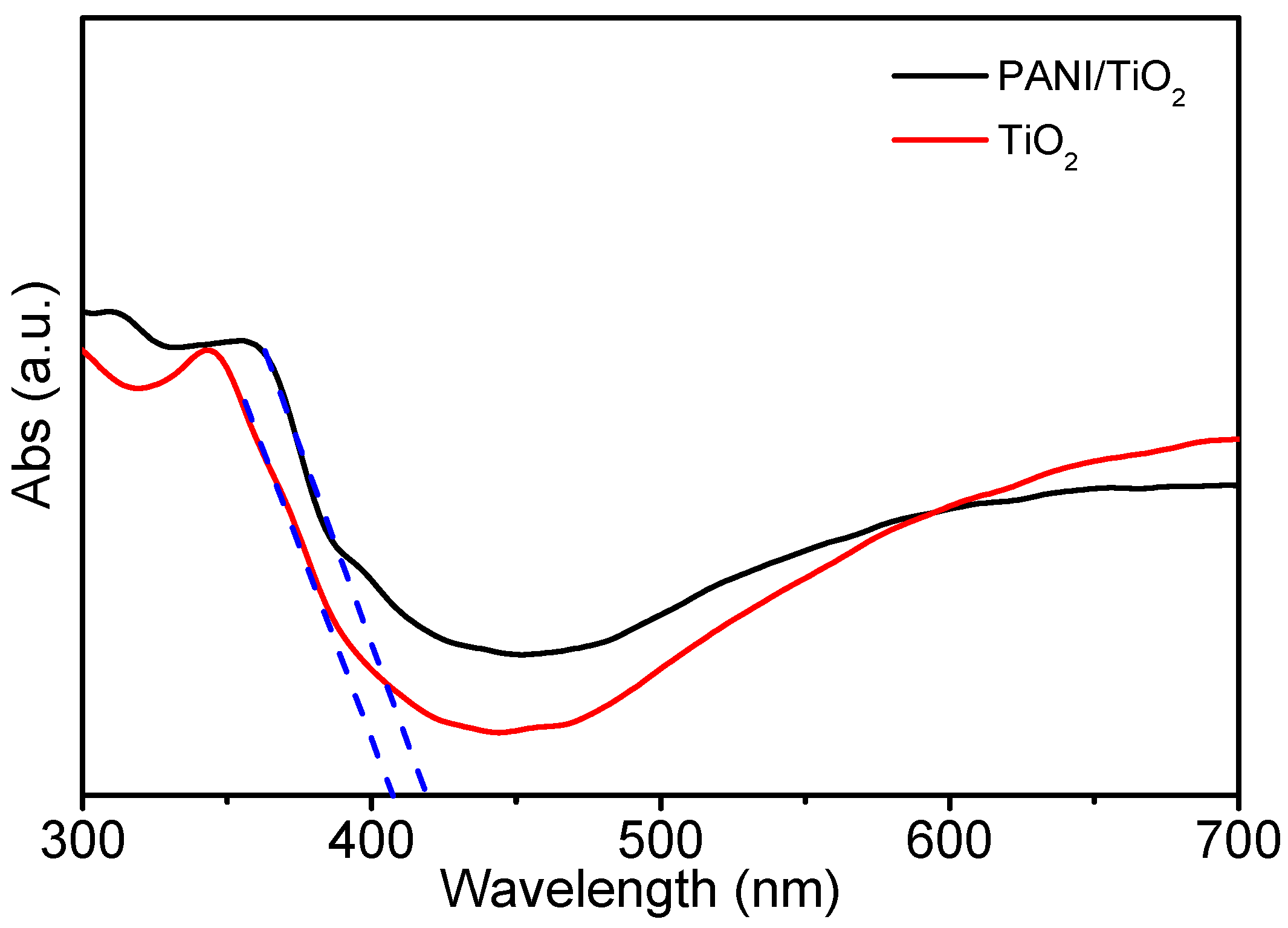
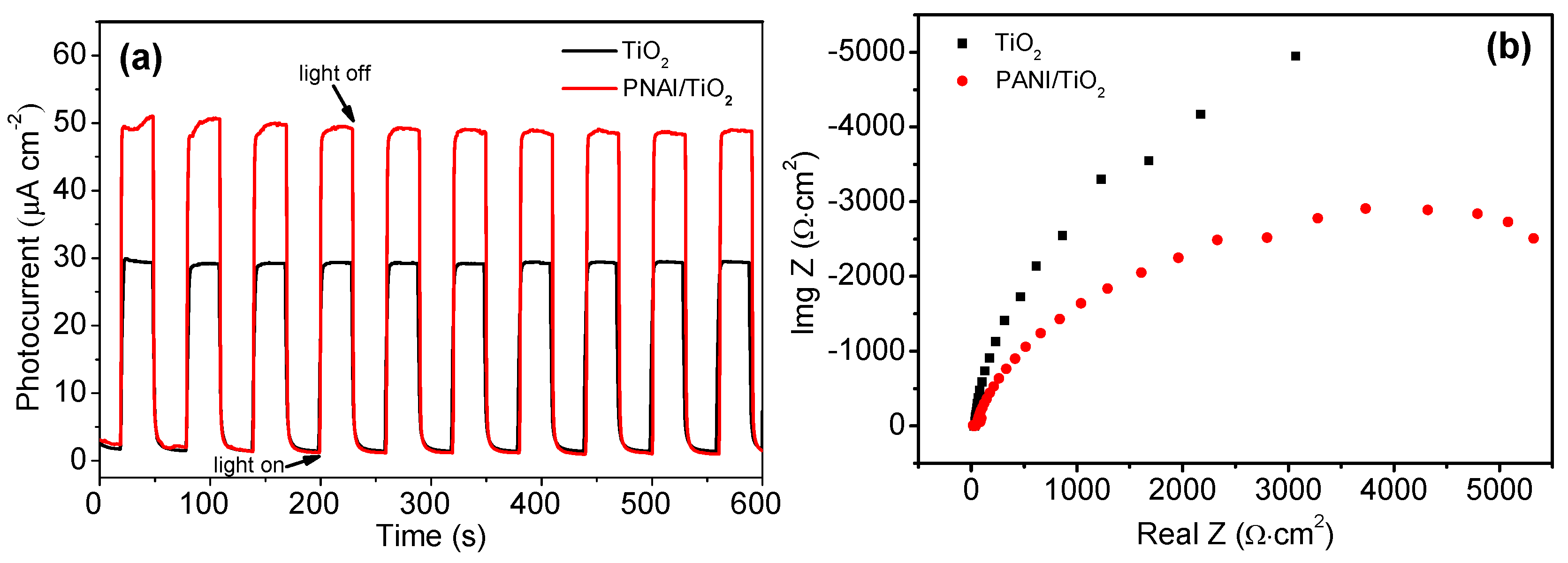
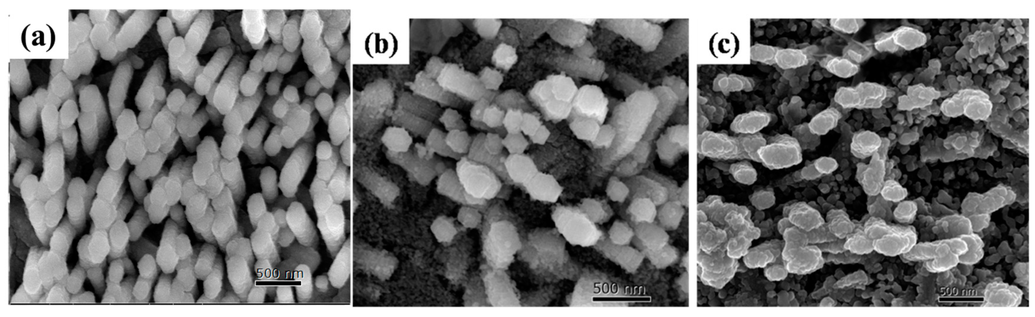
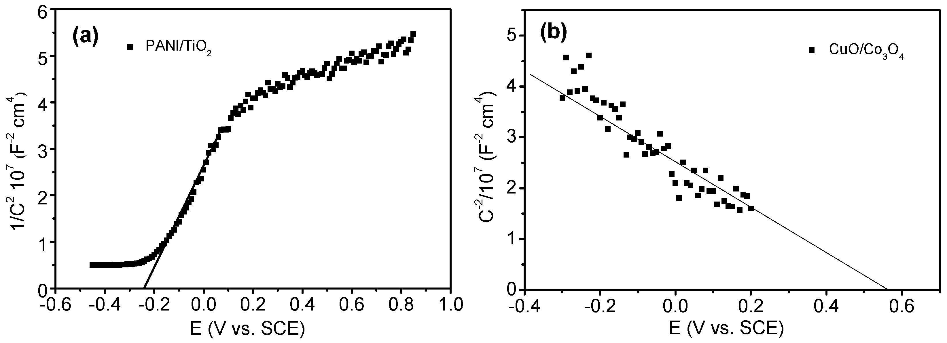
2.1. Characterization of PANI/TiO2 NTs Photoanode

The microstructure and elements distribution of TiO2 and PANI/TiO2 NTs were studied by using Scanning Electron Microscope (SEM) and Energy Dispersive Spectrometer (EDX) (Figure 1), respectively. The TiO2 nanotube arrays were covered by a layer of discretely adhered PANI. As seen in the inset (Figure 1a), the cross-sectional view of TiO2 nanotube arrays substrate clearly displays the vertically oriented nanotubes with a length of about 900 nm and a wall thickness of 10 nm. Additionally, from the EDX analysis, the existence of elements, viz. C, N, Ti and O, was confirmed and especially the minimum quantity of PANI with respect to the content of TiO2 substrate material was confirmed by the relatively low intensities observed against the elements C and N. Figure 2 shows the X-ray diffraction patterns (XRD) recorded for both TiO2 and PANI/TiO2 NTs materials. The peaks presented for PANI/TiO2 NTs reflect characteristics of anatase TiO2 and the predominant peak of 2θ at 25.2° indicates a fine preferential growth of the Titania nanotube (TNTs) in 101 orientation (JCPDS no. 21-1272). The fact that no diffraction peak was observed for PANI might be due to its amorphous phase in the composite. The position and shape of the peaks observed in XRD patterns for PANI/TiO2 NTs were almost identical with that of TiO2, indicate that the incorporation of PANI has no influence in the lattice structure of TiO2, which would be an added advantage for the hybrid photocatalytic material.
Figure 3 shows the Fourier Transform Infrared Spectroscopy (FTIR) spectra recorded for TiO2 and PANI/TiO2 NTs as well. The wide peak observed at 500–800 cm−1 for TiO2 could be ascribed to the Ti–O bending mode of TiO2 sample. The strong characteristic absorption bands observed for PANI/TiO2 NTs, between 1200 and 1600 cm−1, were 1566, 1487, 1299, 1245 and 1127 cm−1. The bands at 1566 and 1487 cm−1 could be correlated to C–C stretching mode of quinonoid and benzenoid units, repectively. The bands at 1299 and 1245 cm−1 represented the C–N stretching mode of benzenoid unit while the band at 1127 cm−1 reflects the plane bending vibration of C=N. The bands at 796 cm−1 represented the C–H stretching mode of benzenoid rings [27]. Furthermore, as seen in Figure 4, the optical responses investigated by UV–vis Diffuse Reflectance Spectra (DRS) for TiO2 and PANI/TiO2 NT samples exhibit a notable absorption extension in the visible-light region at 420 nm upon the incorporation of PANI, which corresponds to a reduced bandgap absorption edge of 2.9 eV. It could be inferred from the red shift of the absorption wavelength that the PANI/TiO2 NTs would be an effective visible-light driven photocatalytic material.
In order to understand the separation and recombination of electron–hole pairs that take place in the photocatalytic materials, the photocurrent and the electrochemical impedance spectra (EIS) measurements were carried out under visible-light irradiation. The transient photocurrent responses of TiO2 and PANI/TiO2 NTs electrodes were recorded via several on–off cycles of irradiation, and the representative traces observed are shown in Figure 5a. Obviously, the intensity of photocurrent response was found to be higher for PANI/TiO2 NTs (50 μA cm−2) than that for TiO2 NTs. The respective Nyquist plots of the TiO2 and PANI/TiO2 NTs photoelectrodes were shown in Figure 5b. The semicircle at high frequencies was characteristic of the charge transfer process and its diameter was equal to the charge transfer resistance. The PANI/TiO2 NTs sample showed a smaller semicircle than that of TiO2 sample in the Nyquist plots. This clearly confirms that the rate of electron transfer between the interface of PANI/TiO2 NTs and the electrolyte was improved as a result of the deposition of PANI which causes the enhanced photoelectrochemical activity of the former compared with that of the latter.
The effects analysis of radicals was carried out in the present study to establish the PEC degradation mechanism as it is proved to be an effective approach in predicting the photodegradation reaction pathways of organic molecules that take place on the surface of the photocatalyst. The nature of interaction between the chosen scavenger and the photocatalyst makes a prominent impact on the efficiency of organic pollutant degradation. The scavengers used in this study were sodium oxalate (Na2C2O4) of 0.5 mmol L−1 [28,29], isopropanol of 1 mmol L−1 [30], Cr(VI) of 0.05 mmol L−1 [28], and p-benzoquinone of 0.5 mmol L−1 [29,30] against h+, •OH, e and O2•−, respectively.
As shown in Figure 6, in the absence of a scavenger, the PEC degradation of Rhodamine B on TiO2 sample at three hours was to an extent of 53%, and it was decreased to 29.4%, 35.8% and 32%, with the addition of scavengers Na2C2O4, isopropanol and p-benzoquinone, respectively, as a separate experiment. However, in the case of Cr(VI) addition, no prominent difference was observed in the efficiency of PEC degradation (52.6%), which could be attributed to the following facts. The addition of Cr(VI) accepts photoelectron and suppresses the reduction of oxygen that results in a decreased production of O2•−, which in turn restrains the degradation of Rhodamine B. On the other hand, Cr(VI) inhibits the recombination of the photoinduced electron and the hole to a certain extent, which could reversely promote the efficiency of PEC degradation. Hence, the addition of Cr(VI) has no impact on the PEC degradation of Rhodamine B. It could be inferred that the major reactive species formed on pure TiO2 were h+, O2•− and •OH.
For the PANI/TiO2 NTs, under similar experimental conditions, the PEC degradation of Rhodamine B decreased from 77%, an actual efficiency obtained without scavenger, to 27.7%, 45% and 28.4% with the addition of Na2C2O4, isopropanol and p-benzoquinone, respectively. Further, with the addition of Cr(VI) scavenger, the PEC degradation of Rhodamine B decreased to an extent of 60.4%. The results suggest that the major reactive species formed on PANI/TiO2 NTs photocatalyst were e, h+, •OH, and O2-with an order of influence as h+ > O2•− > •OH > e.

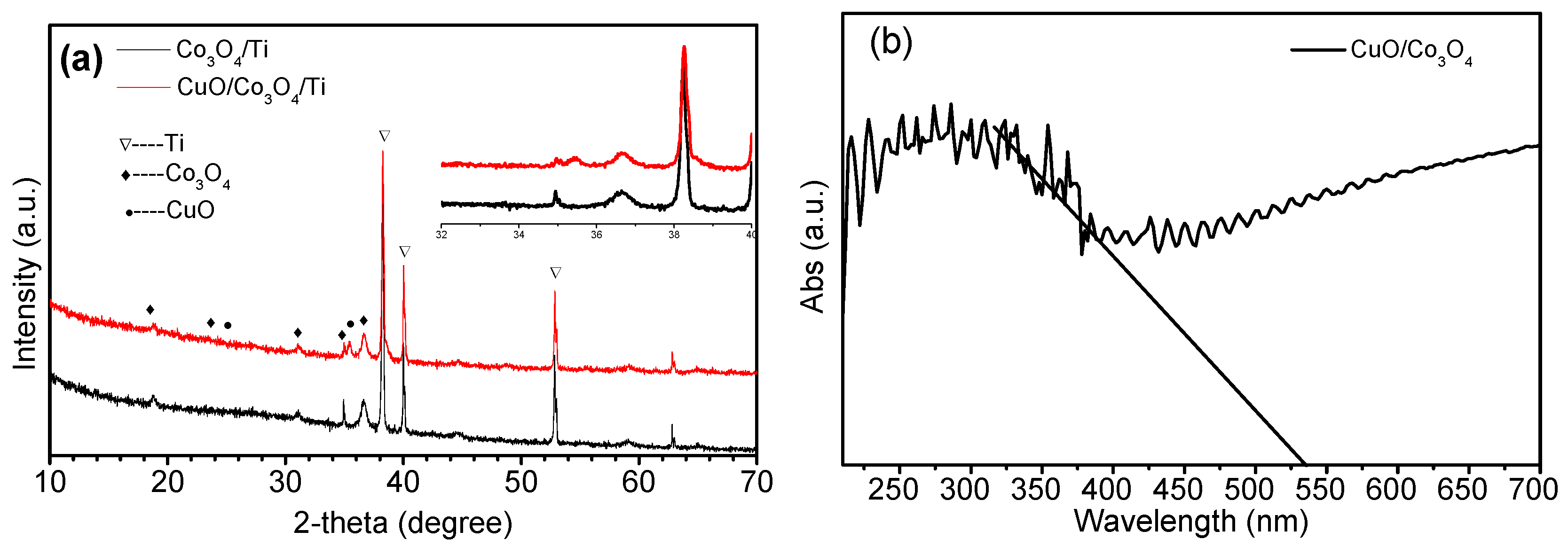
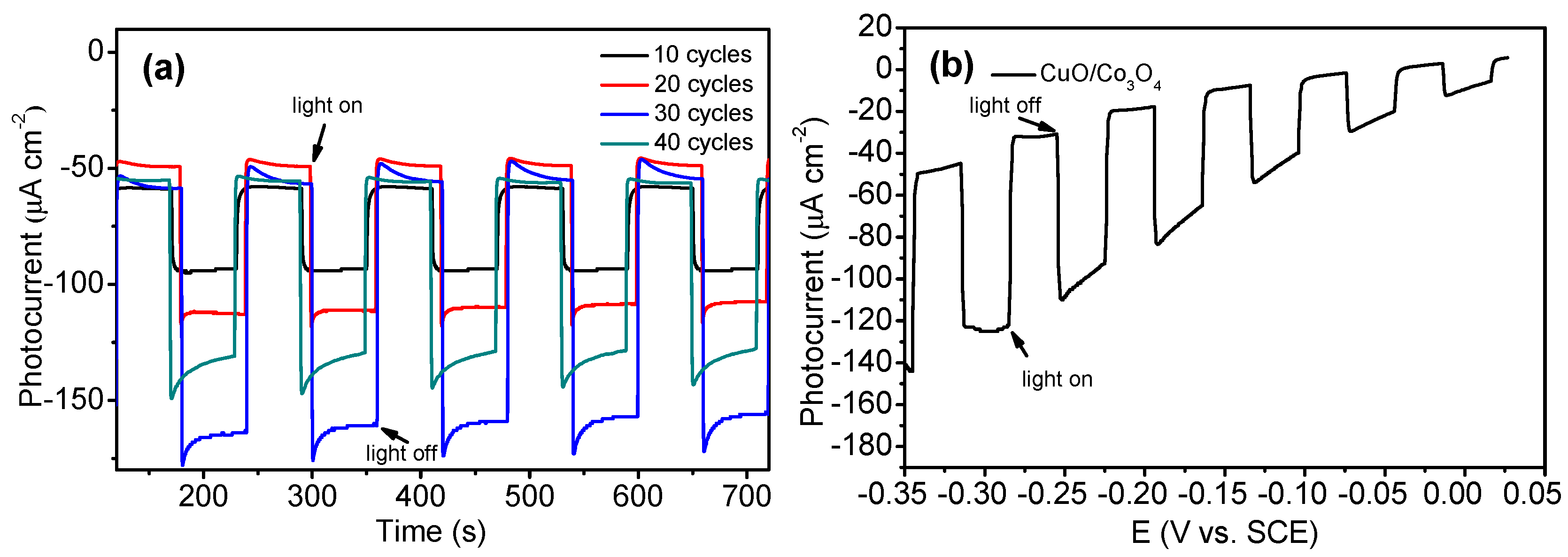
2.2. Characterization of CuO/Co3O4 NRs Photocathode

The SEM images recorded for as-prepared Co3O4 and CuO-coated Co3O4 (CuO/Co3O4) nanorods on the Ti substrate, are shown in Figure 7a,b respectively. As seen, the diameter of the former was observed to be about 150 nm. The CuO/Co3O4 nanorods were fabricated by conducting 30 cycles of pulsed electrodeposition in the aqueous media containing both CuSO4 and lactic acid, followed by an annealing step. As the deposition cycles increase, the CuO NPs started covering the surface of Co3O4 NRs (Figure 7c) gradually and upon 40 cycles, the entire surface was completely covered by CuO NPs which makes it weaken in the adsorption of incident light. The XRD pattern (Figure 8b) revealed the crystal structure and phase purity of both Co3O4 NRs and CuO/Co3O4 NR heterostructures. For Co3O4 NRs, all peaks in the pattern could be indexed using the Co3O4 anatase phase (JPCDS No: 42-1467), and the intense peak of 2θ at 19.0°, 31.2° and 36.5° could be correlated to (111), (200) and (311) plane diffractions, respectively. With the loading of CuO NPs, an additional peak of 2θ at 35.5° was observed in the (111) orientation [31]. This indicates that the deposit made on Co3O4 NRs was only in the form of CuO and not as Cu or Cu2O. As seen in the UV–vis DRS recorded for CuO/Co3O4 NR sample (Figure 8b), a strong absorption was observed in the visible-light region with the band gap energy of 2.33 eV by a linear extrapolation in the absorption edge of the spectrum.
The influence of content of CuO NRs on the PEC performance of CuO/Co3O4 was studied. The NRs were fabricated by pulsed electrodeposition of different cycles, viz. 10, 20, 30 and 40. Figure 9a shows the comparative transient photocurrent response observed in applying the alternative on–off visible-light illumination cycles at −0.25 V (vs. SCE). The CuO/Co3O4 NRs showed an instant photoresponse under irradiation, and the photocurrent densities started increasing initially as the coating cycle increases from 10 to 30, followed by a decrease with a further increase up to 40 cycles. The maximum photocurrent density of about 170 μA cm−2 was observed for CuO/Co3O4 NRs at a coating cycle of 30. Figure 9b shows a linear sweep study for CuO/Co3O4 NRs processed in the potential range of −0.35 V to +0.01 V (vs. SCE) under chopped visible-light irradiation with a scan rate of 0.5 mV s−1. With a cathodic potential scanning, the photocurrent was observed to be increased gradually, which is in accordance with the property of a p-type semiconductor [31]. The CuO/Co3O4 NRs, prepared by 30 cycles of pulsed electrodeposition was chosen as the photocathode for the PFC system of present study as it exhibits the best photoactivity.

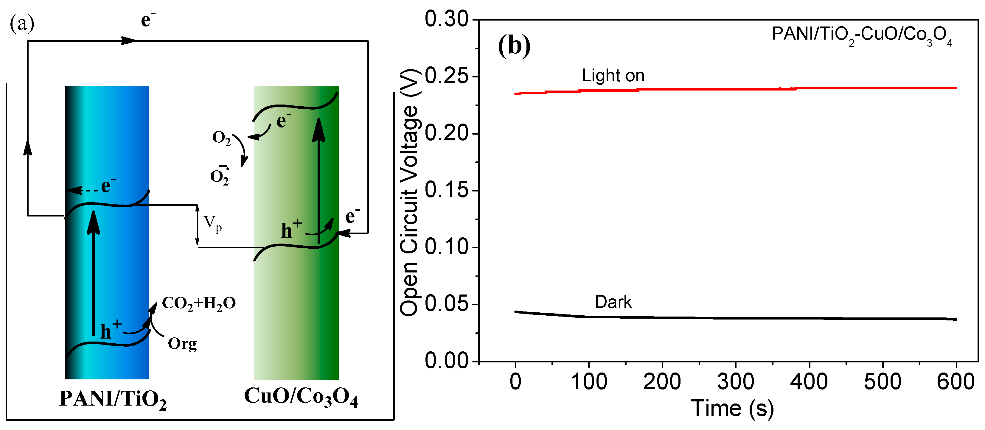
2.3. Characterization of PFC System and Its Performances

Figure 10 shows the Mott–Schottky (MS) plots depicted as 1/C2 vs. potential at 100 Hz for the respective PANI/TiO2 NTs and CuO/Co3O4 NRs samples. The slopes of the linear part of the curves in the MS plot for the PANI/TiO2 NTs were positive, which is a characteristic behavior of typical n-type semiconductor. The linear parts of the curves were x-extrapolated to zero, to obtain the Vfb value [32,33] of ca. −0.25 V vs. SCE for the PANI/TiO2 NTs (Figure 10a), which represents its conduction band edge (CB). Conversely, the p-type characteristic behavior of CuO/Co3O4 NRs was verified by a negative slope in the MS plot, as seen in Figure 10b. The valence band (VB) edge +0.58 V vs. SCE was approximately equal to the flatband position.
The energy band positions of the photoanode and photocahotde are illustrated in Figure 11a. As the Fermi level of CuO/Co3O4 NRs is more positive than that of PANI/TiO2 NTs, an interior bias could be formed by connecting the two photoelectrodes directly, which would obviously drive the electrons generated from PANI/TiO2 NTs through the external circuit and combine with the holes generated in CuO/Co3O4 NRs. Meanwhile, the holes and the electrons remained in the respective photoelectrode can be very well utilized for degradation of organic pollutant. It is actually the key factor that makes the PEC technique successful by combining n-type photoanode and p-type photocathode.
The open circuit potential (Eocp) was established from the difference in the Fermi level of the two photoelectrodes [32,33]. To examine the photoelectric properties of the PFC, the photovoltage curves of the PFC system of PANI/TiO2-CuO/Co3O4 was measured in the dark and under irradiation. Eocp of the PANI/TiO2 NTs photoanode and the CuO/Co3O4 NRs photocathode were measured to be −0.13 V and 0.12 V, respectively, under visible-light irradiation (3 mW cm−2). It implies that the photovoltage between the photocathode and the photoanode would be +0.25 V which is consistent with the measured value (+0.24 V) of the PFC system, as shown in Figure 11b. As a result, the separation of the electron/hole pair in the photoelectrodes could be facilitated in parallel under visible-light irradiation.

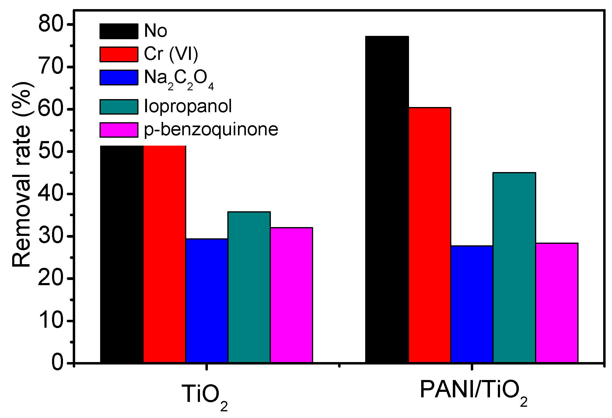
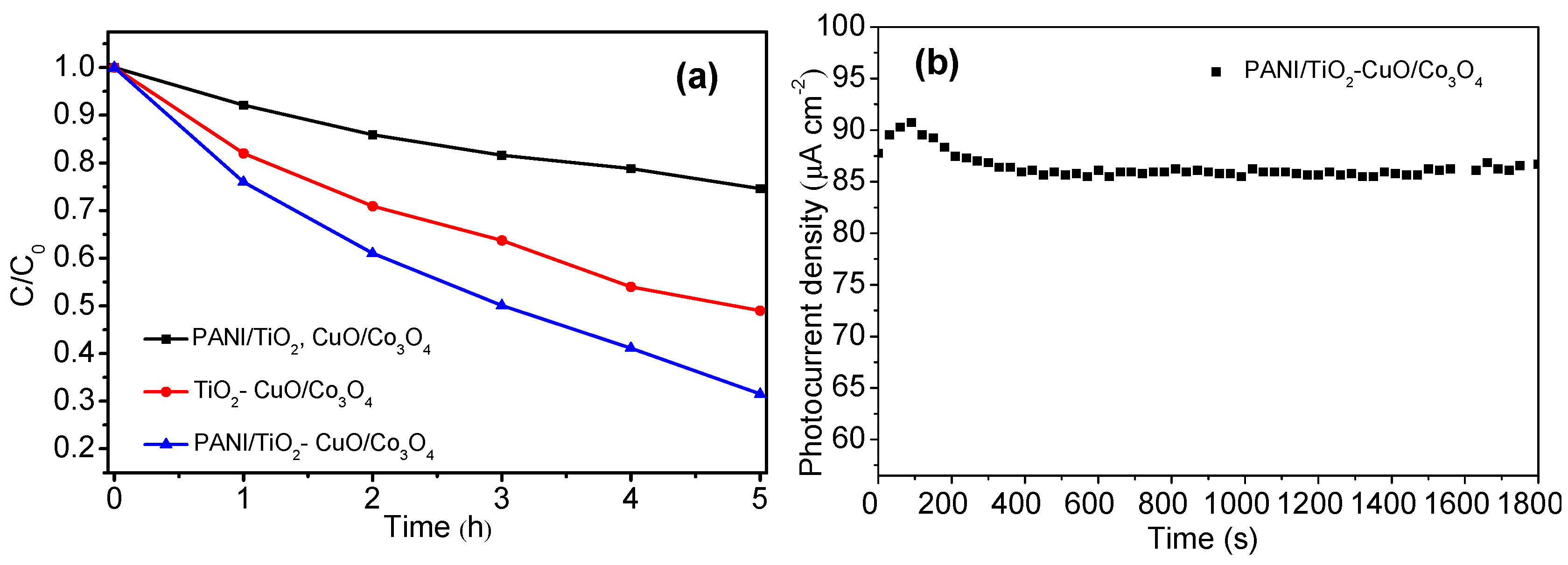
2.4. Degradation of Rhodamine B

The performance of the PFC system was evaluated by a degradation study on Rhodamine B contaminated aqueous solution under visible-light irradiation. The degradation efficiency was monitored in terms of decolorization of Rhodamine B. The photocatalytic activity of various systems using different types of photocatalysts was compared under incandescent light irradiation as shown in Figure 12a. As seen, the photocatalytic activity of the system in which the photoelectrodes are not externally interconnected, was found to be inferior to the others and showing a decolorization of Rhodamine B of only 25.4%. For the PFC system of different photoelectrode couples TiO2-CuO/Co3O4, and PANI/TiO2-CuO/Co3O4 the decolorization was 51% and 68%, respectively at same reaction period. Figure 12b demonstrates that the short-circuit current density curve obtained for the present PFC system (PANI/TiO2-CuO/Co3O4) during the process of Rhodamine B decolorization, was relatively steady with a current density of 85 μA cm−2 throughout the process. The consistent photocurrent density observed for the PFC confirmed its photostability and durability for long-time application.

3. Materials and Methods

3.1. Chemical and Material

Titanium foil with a thickness of 1 mm and a purity of 99.9% was purchased from Strem Chemicals (Newburyport, MA, USA). The chemicals such as ethylene glycol (EG), ammonia fluoride (NH4F), sodium sulfate (Na2SO4), phenylamine (C6H5NH2), cobalt nitrate hexahydrate (Co(NO3)2∙6H2O), hexamethylenetetramine (C6H12N4, HMT), sodium persulfate (Na2S2O3) and HCl were purchased from Acros Organics (Pittsburgh, PA, USA) and used as received. The aqueous solution used was prepared by using a millipore deionized (DI) water with a resistivity of 18.2 MΩ cm.

3.2. Preparation of PANI/TiO2-NTs

The self-organized TiO2 nanotube arrays (TiO2-NTs) were fabricated on Ti foil substrate by anodization method using ethylene glycol (EG) as electrolyte media which contains 0.5 wt % NH4F and 10 vol % water. The fabrication process was described in detail in our previous studies [34]. The anodization of Ti foil was performed with a two-electrode electrochemical system employing Pt mesh as cathode at a constant operating potential of 20 V for a period of 2 h. The inter electrode gap was fixed as 3 cm for every electrolysis run. In the post treatment, the anodized sample was washed with millipore deionized water, dried at 70 °C and calcined at 450 °C for 2 h.
The PANI/TiO2 NTs composite was synthesized by a sequential chemical bath deposition (SCBD) method. Typically, the TiO2 NTs was successively immersed into four different glass beakers for about 30 min in each beaker. The first beaker contained aqueous solution of 0.27 mol L−1 of phenylamine, and the third one contained an aqueous mixture of 0.23 mol L−1 of sodium persulfate and 0.15 mol L−1 of HCl, and the other two contained distilled water to rinse the samples to scavenge the excess of each precursor solution. Such an immersion treatment cycle was repeated thrice.

3.3. Preparation of CuO/Co3O4

The synthesis of Co3O4 electrode was accomplished by a simple hydrothermal process [35]. 7.2 g of Co(NO3)2∙6H2O, 0.13 g of NH4F, and 0.3 g of HMT were dissolved in the order in a 50-mL acetone−deionized water (v/v = 50:50) mixture solution under continuous stirring using magnetic stirrer. Upon a formation of pink suspension, the stirring was continued for another 10 min. Then the suspension, together with a Ti film, was transformed to a teflon-lined stainless-steel autoclave vessel and kept for 24 h at 95 °C. The pink-depositions-covered-Ti film was obtained by these steps, and carefully rinsed with deionized water and dried at 70 °C, followed by a calcination process at 350 °C for 1 h in air environment. The transformation of pink depositions into black one upon calcinations confirmed the formation of Co3O4.
CuO was prepared by a pulsed galvanostat method under high current conditions [36]. The electrodeposition was carried out in a conventional three-electrode electrochemical workstation (CS310, CorrTest, Wuhan, China) with a conditioned electrolyte solution of 0.4 mol L−1 CuSO4 and 3 mol L−1 lactic acid fixing the pH at 7 by NaOH and the temperature at 25 °C. The concentrated lactic acid acts as a complex agent for the stabilization of copper ions [37]. Upon subjecting to a negative current pulse for 0.5 s followed by a constant current density of 50 mA for 7 s, the surface of the Co3O4 was covered with Cu nanoparticles (NPs). The as-prepared electrode was carefully rinsed with millipore deionized water and dried at 70 °C, followed by a calcination process at 350 °C for 1 h. Then the samples were rinsed with ethanol, followed by a heat treatment at 450 °C for 1 h in air environment. In order to optimize the deposition of CuO NPs on the Co3O4, the samples were fabricated at different pulse cycles, viz. 10, 20, 30 and 40.

3.4. Characterization

The morphology and microstructure of the synthesized samples were characterized by field emission scanning electron microscopy (FE-SEM; NANOSEM 450, FEI, Eindhoven, The Netherlands). The phase and elemental composition of the samples were investigated using X-ray Diffraction Technique (XRD; PW3040/60 PANalytical, Almelo, The Netherlands) with Cu K α radiation (λ = 1.54056 Å). UV–visible spectrum scanning was carried out in the range of 200–800 nm using a UV-2550 model UV–visible spectrophotometer (Shimadzu Corporation, Kanagawa, Japan) at room temperature. The infrared absorption spectra were measured on a Bruker V-70 Fourier transform infrared (FTIR, Bruker, Karlsruhe, Germany) spectrophotometer in the frequency range of 400 to 4000 cm−1.
The photoresponsive test was carried out for the sample (either PANI/TiO2 NTs or CuO/Co3O4 NRs) used as working electrode in a three-electrode electrochemical work station (CS310, CorrTest, Wuhan, China), wherein saturated calomel electrode (SCE) and Pt foil was used as reference and auxiliary electrodes, respectively. The electrochemical impedance spectroscopic (EIS) studies were performed between 100 kHz and 0.01 Hz with a 5 mV rms sinusoidal modulation at the open circuit potential of the system under illumination. The linear sweep was evaluated under chopped light irradiation with a scan rate of 0.5 mV s−1. Mott–Schottky plots were measured at a frequency of 100 Hz. The electrochemical studies described above were carried out in a 0.1 mol L−1 Na2SO4 aqueous solution at room temperature. The light source used was a 11 W incandescent lamp (PHILPS, Amsterdam, The Netherlands) that produced irradiation with an intensity of 3 mW cm−2 to the test sample which was measured by a visible-light radiometer (FZ-A, Wuhan, China).
The photoelectrochemical characteristics of the PFC were examined by connecting PANI/TiO2 NTs electrode and CuO/Co3O4 NRs electrode directly. The short circuit current plot, and the open circuit potentials plot as well as the characteristic nature of photocurrent potentials were tested by digit precision multimeter (Tektronix DMM4050, Johnston, OH, USA) and the electrochemical workstation, respectively.

3.5. Photoelectrocatalytic Degradation of Phenol under Visible-Light Irradiation

Photoelectrocatalytic oxidation experiments were carried out in a glass container having volume capacity of 150 mL with a standard three-electrode configuration using synthesized PANI/TiO2-NTs as photoanode, a Pt foil and a SCE as counter and reference electrodes, respectively. The photoelectrochemical degradation experiments were performed with a working volume of 45 mL aqueous solution containing a model contaminant Rhodamine B (1 × 10⁻⁵ mol L−1) along with 0.1 mol L−1 Na2SO4 as supporting electrolyte. The glass container was placed in a water bath wherein the temperature was constantly maintained as 298 K, and the entire set-up was placed on a magnetic stirrer operated at a constant stirring rate of 650 rpm during the process. Prior to the light irradiation, the experimental solution was stirred in the dark for ca. 30 min to establish the adsorption/desorption equilibrium between the organic contaminant and the surface of the PANI/TiO2-NTs under ambient air equilibrium. The degradation rate of Rhodamine B was followed by using a UV–vis spectrophotometer (UV2102 PCS, UNICO, Shanghai, China) in which the wavelength was fixed at 554 nm.
The PFC degradation of Rhodamine B (1 × 10⁻⁵ mol L−1) was performed by exposing the light on both the PANI/TiO2-NTs photoanode and CuO/Co3O4 photocathode with the illumination area of 2 × 2 cm2 under similar conditions to those followed in the photoelectrocatalytic experiment. The PFC current was measured by using a digit precision multimeter.

4. Conclusions

A highly efficient and visible-light responsive photocatalytic fuel cell (PFC) system involving a dual heterojuntion PANI/TiO2 photoanode and CuO/Co3O4 photocathode was constructed. The results obtained showed that a photocurrent of 50 μA cm−2 was achieved using the PANI/TiO2 photoanode at a bias potential of +0.6 V (vs. SCE) in 0.1 mol L−1 Na2SO4 electrolyte under visible-light irradiation of 3 mW cm−2, which was 150% higher than that of TiO2. Additionally, the optimized CuO/Co3O4 photocathode exhibited a photocurrent of 170 μA cm−2 at −0.25 V (vs. SCE). The PFC was constructed with the aim of providing an internal bias potential to the photoelectrocatalytic system and the performance and working mechanism of the same were systematically investigated. Under visible-light irradiation, the interior bias (+0.24 V) developed, drives the electrons of the PANI/TiO2-NT’s photoanode across the external circuit to combine with the holes of the CuO/Co3O4 photocathode, which actually leads to electron/hole pair separation at respective photoelectrodes. The results obtained in the study suggest that the PFC system involving dual heterojuntion PANI/TiO2 photoanode and CuO/Co3O4 photocathode is very effective for wastewater treatment along with simultaneous electricity generation.

Acknowledgments

This work was supported by the International Science & Technology Cooperation Program of China (Nos. 2013DFG50150 and 2016YFE0126300) and the Innovative and Interdisciplinary Team at HUST (2015ZDTD027). The authors thank the Analytical and Testing Center of HUST for the use of SEM, XRD, TEM, FTIR and DRS equipments.

Author Contributions

Yanrong Zhang and Muthu Murugananthan conceived and designed the experiments; Wenjuan Liao and Na Sun performed the experiments; Honghui Pan contributed analysis tools; Wenjuan Liao wrote the paper.

Conflicts of Interest

The authors declare no conflict of interest.

References

  1. Feng, Y.; Lee, H.; Wang, X.; Liu, Y.; He, W. Continuous electricity generation by a graphite granule baffled air–cathode microbial fuel cell. Bioresour. Technol. 2010, 101, 632–638. [Google Scholar] [CrossRef] [PubMed]
  2. Strataki, N.; Antoniadou, M.; Dracopoulos, V.; Lianos, P. Visible-light photocatalytic hydrogen production from ethanol–water mixtures using a Pt–CdS–TiO2 photocatalyst. Catal. Today 2010, 151, 53–57. [Google Scholar] [CrossRef]
  3. Liu, Y.; Li, J.; Zhou, B.; Li, X.; Chen, H.; Chen, Q.; Wang, Z.; Li, L.; Wang, J.; Cai, W. Efficient electricity production and simultaneously wastewater treatment via a high-performance photocatalytic fuel cell. Water Res. 2011, 45, 3991–3998. [Google Scholar] [CrossRef] [PubMed]
  4. Bayati, M.R.; Golestani-Fard, F.; Moshfegh, A.Z. Visible photodecomposition of methylene blue over micro arc oxidized WO3–loaded TiO2 nano-porous layers. Appl. Catal. A 2010, 382, 322–331. [Google Scholar] [CrossRef]
  5. Lu, B.; Ma, X.; Pan, C.; Zhu, Y. Photocatalytic and photoelectrochemical properties of in situ carbon hybridized BiPO4 films. Appl. Catal. A 2012, 435–436, 93–98. [Google Scholar] [CrossRef]
  6. Chen, D.; Ye, J. Hierarchical WO3 Hollow Shells: Dendrite, Sphere, Dumbbell, and Their Photocatalytic Properties. Adv. Funct. Mater. 2008, 18, 1922–1928. [Google Scholar] [CrossRef]
  7. Antoniadou, M.; Kondarides, D.; Labou, D.; Neophytides, S.; Lianos, P. An efficient photoelectrochemical cell functioning in the presence of organic wastes. Sol. Energy Mater. Sol. Cells 2010, 94, 592–597. [Google Scholar] [CrossRef]
  8. Lianos, P. Production of electricity and hydrogen by photocatalytic degradation of organic wastes in a photoelectrochemical cell: The concept of the Photofuelcell: A review of a re-emerging research field. J. Hazard. Mater. 2011, 185, 575–590. [Google Scholar] [CrossRef] [PubMed]
  9. Liu, Y.; Li, J.; Zhou, B.; Lv, S.; Li, X.; Chen, H.; Chen, Q.; Cai, W. Photoelectrocatalytic degradation of refractory organic compounds enhanced by a photocatalytic fuel cell. Appl. Catal. B 2012, 111–112, 485–491. [Google Scholar] [CrossRef]
  10. Liu, Y.; Li, J.; Zhou, B.; Chen, H.; Wang, Z.; Cai, W. A TiO2-nanotube-array-based photocatalytic fuel cell using refractory organic compounds as substrates for electricity generation. Chem. Commun. 2011, 47, 10314–10316. [Google Scholar] [CrossRef] [PubMed]
  11. Georgieva, J.; Valova, E.; Armyanov, S.; Philippidis, N.; Poulios, I.; Sotiropoulos, S. Bi-component semiconductor oxide photoanodes for the photoelectrocatalytic oxidation of organic solutes and vapours: A short review with emphasis to TiO2–WO3 photoanodes. J. Hazard. Mater. 2012, 211–212, 30–46. [Google Scholar] [CrossRef] [PubMed]
  12. Li, K.; Zhang, H.; Tang, Y.; Ying, D.; Xu, Y.; Wang, Y.; Jia, J. Photocatalytic degradation and electricity generation in a rotating disk photoelectrochemical cell over hierarchical structured BiOBr film. Appl. Catal. B 2015, 164, 82–91. [Google Scholar] [CrossRef]
  13. Wang, D.; Li, Y.; Li Puma, G.; Wang, C.; Wang, P.; Zhang, W.; Wang, Q. Dye-sensitized photoelectrochemical cell on plasmonic Ag/AgCl @ chiral TiO2 nanofibers for treatment of urban wastewater effluents, with simultaneous production of hydrogen and electricity. Appl. Catal. B 2015, 168–169, 25–32. [Google Scholar] [CrossRef] [Green Version]
  14. Du, Y.; Feng, Y.; Qu, Y.; Liu, J.; Ren, N.; Liu, H. Electricity Generation and Pollutant Degradation Using a Novel Biocathode Coupled Photoelectrochemical Cell. Environ. Sci. Technol. 2014, 48, 7634–7641. [Google Scholar] [CrossRef] [PubMed]
  15. Li, J.; Li, J.; Chen, Q.; Bai, J.; Zhou, B. Converting hazardous organics into clean energy using a solar responsive dual photoelectrode photocatalytic fuel cell. J. Hazard. Mater. 2013, 262, 304–310. [Google Scholar] [CrossRef] [PubMed]
  16. Chen, Q.; Li, J.; Li, X.; Huang, K.; Zhou, B.; Shangguan, W. Self-Biasing Photoelectrochemical Cell for Spontaneous Overall Water Splitting under Visible-Light Illumination. ChemSusChem 2013, 6, 1276–1281. [Google Scholar] [CrossRef] [PubMed]
  17. Paracchino, A.; Laporte, V.; Sivula, K.; Grätzel, M.; Thimsen, E. Highly active oxide photocathode for photoelectrochemical water reduction. Nat. Mater. 2011, 10, 456–461. [Google Scholar] [CrossRef] [PubMed]
  18. Bai, J.; Wang, R.; Li, Y.; Tang, Y.; Zeng, Q.; Xia, L.; Li, X.; Li, J.; Li, C.; Zhou, B. A solar light driven dual photoelectrode photocatalytic fuel cell (PFC) for simultaneous wastewater treatment and electricity generation. J. Hazard. Mater. 2016, 311, 51–62. [Google Scholar] [CrossRef] [PubMed]
  19. Wang, H.; Zhang, L.; Chen, Z.; Hu, J.; Li, S.; Wang, Z.; Liu, J.; Wang, X. Semiconductor heterojunction photocatalysts: Design, construction, and photocatalytic performances. Chem. Soc. Rev. 2014, 43, 5234–5244. [Google Scholar] [CrossRef] [PubMed]
  20. Liao, G.; Chen, S.; Quan, X.; Zhang, Y.; Zhao, H. Remarkable improvement of visible light photocatalysis with PANI modified core–shell mesoporous TiO2 microspheres. Appl. Catal. B 2011, 102, 126–131. [Google Scholar] [CrossRef]
  21. Li, X.; Wang, D.; Cheng, G.; Luo, Q.; An, J.; Wang, Y. Preparation of polyaniline-modified TiO2 nanoparticles and their photocatalytic activity under visible light illumination. Appl. Catal. B 2008, 81, 267–273. [Google Scholar] [CrossRef]
  22. Liu, J.; Wang, D.; Wang, M.; Kong, D.; Zhang, Y.; Chen, J.F.; Dai, L. Uniform Two-dimensional Co3O4 Porous Sheets: Facile Synthesis and Enhanced Photocatalytic Performance. Chem. Eng. Technol. 2016, 39, 891–898. [Google Scholar] [CrossRef]
  23. Yehezkeli, O.; de Oliveira, D.R.; Cha, J.N. Electrostatically Assembled CdS–Co3O4 Nanostructures for Photo-assisted Water Oxidation and Photocatalytic Reduction of Dye Molecules. Small 2015, 11, 668–674. [Google Scholar] [CrossRef] [PubMed]
  24. Shaabani, B.; Alizadeh-Gheshlaghi, E.; Azizian-Kalandaragh, Y.; Khodayari, A. Preparation of CuO nanopowders and their catalytic activity in photodegradation of Rhodamine-B. Adv. Powder Technol. 2014, 25, 1043–1052. [Google Scholar] [CrossRef]
  25. Shi, W.; Chopra, N. Surfactant-free synthesis of novel copper oxide (CuO) nanowire–cobalt oxide (Co3O4) nanoparticle heterostructures and their morphological control. J. Nanopart. Res. 2011, 13, 851–868. [Google Scholar] [CrossRef]
  26. Shi, W.; Chopra, N. Controlled fabrication of photoactive copper oxide–cobalt oxide nanowire heterostructures for efficient phenol photodegradation. ACS Appl. Mater. Interfaces 2012, 4, 5590–5607. [Google Scholar] [CrossRef] [PubMed]
  27. Yavuz, A.G.; Gök, A. Preparation of TiO2/PANI composites in the presence of surfactants and investigation of electrical properties. Synth. Met. 2007, 157, 235–242. [Google Scholar] [CrossRef]
  28. Liao, W.; Zhang, Y.; Zhang, M.; Murugananthan, M.; Yoshihara, S. Photoelectrocatalytic degradation of microcystin-LR using Ag/AgCl/TiO2 nanotube arrays electrode under visible light irradiation. Chem. Eng. J. 2013, 231, 455–463. [Google Scholar] [CrossRef]
  29. Chen, S.; Hu, Y.; Meng, S.; Fu, X. Study on the separation mechanisms of photogenerated electrons and holes for composite photocatalysts g-C3N4-WO3. Appl. Catal. B 2014, 150–151, 564–573. [Google Scholar] [CrossRef]
  30. Yang, Y.; Guo, W.; Guo, Y.; Zhao, Y.; Yuan, X.; Guo, Y. Fabrication of Z-scheme plasmonic photocatalyst Ag@ AgBr/g-C3N4 with enhanced visible-light photocatalytic activity. J. Hazard. Mater. 2014, 271, 150–159. [Google Scholar] [CrossRef] [PubMed]
  31. Yang, J.; Liao, W.; Liu, Y.; Murugananthan, M.; Zhang, Y. Degradation of Rhodamine B using a Visible-light driven Photocatalytic Fuel Cell. Electrochim. Acta 2014, 144, 7–15. [Google Scholar] [CrossRef]
  32. Spadavecchia, F.; Cappelletti, G.; Ardizzone, S.; Ceotto, M.; Falciola, L. Electronic structure of pure and N-doped TiO2 nanocrystals by electrochemical experiments and first principles calculations. J. Phys. Chem. C 2011, 115, 6381–6391. [Google Scholar] [CrossRef]
  33. Gu, J.; Yan, Y.; Krizan, J.W.; Gibson, Q.D.; Detweiler, Z.M.; Cava, R.J.; Bocarsly, A.B. p-Type CuRhO2 as a self-healing photoelectrode for water reduction under visible light. J. Am. Chem. Soc. 2014, 136, 830–833. [Google Scholar] [CrossRef] [PubMed]
  34. Zhou, H.; Zhang, Y. Enhanced electrochemical performance of manganese dioxide spheres deposited on a titanium dioxide nanotube arrays substrate. J. Power Sources 2014, 272, 866–879. [Google Scholar] [CrossRef]
  35. Huang, X.; Cao, T.; Liu, M.; Zhao, G. Synergistic Photoelectrochemical Synthesis of Formate from CO2 on {121̅} Hierarchical Co3O4. J. Phys. Chem. C 2013, 117, 26432–26440. [Google Scholar] [CrossRef]
  36. Shen, Q.; Chen, Z.; Huang, X.; Liu, M.; Zhao, G. High-yield and selective photoelectrocatalytic reduction of CO2 to formate by metallic copper decorated Co3O4 nanotube arrays. Environ. Sci. Technol. 2015, 49, 5828–5835. [Google Scholar] [CrossRef] [PubMed]
  37. Lee, C.Y.; Lee, K.; Schmuki, P. Anodic Formation of Self-Organized Cobalt Oxide Nanoporous Layers. Angew. Chem. Int. Ed. 2013, 52, 2077–2081. [Google Scholar] [CrossRef] [PubMed]
Figure 1. (a) SEM image of the TiO2 (the inset shows the cross-sectional image) and (b) polyaniline (PANI)/TiO2 nanotubes (NTs), (c) EDX analysis of (b).
Catalysts 08 00030 g001
Figure 2. XRD patterns recorded for TiO2, and PANI/TiO2 NTs.
Catalysts 08 00030 g002
Figure 3. FTIR spectra of the TiO2 and PANI/TiO2 NTs.
Catalysts 08 00030 g003
Figure 4. UV–vis diffuse reflection spectra of the TiO2 and PANI/TiO2 NTs.
Catalysts 08 00030 g004
Figure 5. (a) Photocurrent responses of TiO2 and PANI/TiO2 NTs in 0.1 mol L−1 Na2SO4 at a bias potential of +0.6 V (vs. saturated calomel electrode (SCE)); (b) Nyquist plots of TiO2 and PANI/TiO2 NTs measured at open circuit potential under irradiation.
Catalysts 08 00030 g005
Figure 6. Effects of different scavengers on the PEC degradation of Rhodamine B (0.05 mmol L−1 Cr(VI): e scavenger, 1 mmol L−1 isopropanol: •OH scavenger, 0.5 mmol L−1 p-benzoquinone: O2•−, 0.5 mmol L−1 sodium oxalate: h+ scavenger).
Catalysts 08 00030 g006
Figure 7. SEM images of the Co3O4 (a), CuO (30)/Co3O4 (b) and CuO (40)/Co3O4 (c).
Catalysts 08 00030 g007
Figure 8. (a) XRD of the Co3O4 and CuO (30)/Co3O4, (b) UV–vis DRS of CuO (30)/Co3O4.
Catalysts 08 00030 g008
Figure 9. (a) PEC performance of the composite samples prepared at different pulse cycles at −0.25 V (vs. SCE) under visible-light irradiation in 0.1 mol L−1 Na2SO4 aqueous solution and (b) Linear sweep voltammetry (LSV) curves of CuO(30)/Co3O4 in 0.1 mol L−1 Na2SO4 solution in dark and under visible-light irradiation.
Catalysts 08 00030 g009
Figure 10. Mott–Schottky plots measured at a frequency of 100 Hz of (a) PANI/TiO2 NTs, (b) CuO/Co3O4 NRs in the dark.
Catalysts 08 00030 g010
Figure 11. (a) Energy level diagram of the PFC cell for organic compounds degradation and electricity generation, (b) The open-circuit voltage of PFC cell of PANI/TiO2-CuO/Co3O4 in dark and under visible-light irradiation.
Catalysts 08 00030 g011
Figure 12. (a) Comparison of the degradation rates of Rhodamine B in the photocatalytic decomposition processes using unconnected PANI/TiO2 and CuO/Co3O4 photoelectrodes, the PFC systems of TiO2CuO/Co3O4 and PANI/TiO2-CuO/Co3O4, (b) the generated electricity of the PFC.
Catalysts 08 00030 g012

