Article

An Oxygen Reduction Study of Graphene-Based Nanomaterials of Different Origin

1
Institute of Chemistry, University of Tartu, Ravila 14a, 50411 Tartu, Estonia
2
Institute of Physics, University of Tartu, W. Ostwald Str. 1, 50411 Tartu, Estonia
3
Institute of Chemistry, UFMS, CP 549, Campo Grande MS 79070-900, Brazil
*
Author to whom correspondence should be addressed.
Catalysts 2016, 6(7), 108; https://doi.org/10.3390/catal6070108
Submission received: 13 June 2016 / Revised: 8 July 2016 / Accepted: 12 July 2016 / Published: 22 July 2016
(This article belongs to the Special Issue Carbon Materials for Green Catalysis)

Abstract

:
The aim of this study is to compare the electrochemical behaviour of graphene-based materials of different origin, e.g., commercially available graphene nanosheets from two producers and reduced graphene oxide (rGO) towards the oxygen reduction reaction (ORR) using linear sweep voltammetry, rotating disc electrode and rotating ring-disc electrode methods. We also investigate the effect of catalyst ink preparation using two different solvents (2-propanol containing OH ionomer or N,N-dimethylformamide) on the ORR. The graphene-based materials are characterised by scanning electron microscopy, transmission electron microscopy, Raman spectroscopy and X-ray photoelectron spectroscopy. Clearly, the catalytic effect depends on the origin of graphene material and, interestingly, the electrocatalytic activity of the catalyst material for ORR is lower when using the OH ionomer in electrode modification. The graphene electrodes fabricated with commercial graphene show better ORR performance than rGO in alkaline solution.

Graphical Abstract

1. Introduction

Graphene is a novel carbon-based material, which was first isolated in 2004 by Novoselov and Geim [1]. While graphene has very interesting properties, for example high surface area (the theoretical specific surface area of single layer graphene is 2630 m2·g−1), good electrical conductivity (550 S·cm−1) and mechanical strength (Young’s modulus ca. 1 TPa) [2,3,4,5,6], scientists have extensively used graphene for fundamental investigations, including the fields of electroanalysis and electrocatalysis. In addition, graphene has been considered as a promising support material in industrial applications including but not limited to (bio)sensors, solar cells, batteries and fuel cells [7,8,9,10,11,12,13,14]. In an ideal way, graphene is a two-dimensional allotrope of carbon with an atomic thickness of ca. 0.34 nm, where the carbon atoms are densely packed forming a hexagonal pattern of graphene nanosheet revealing a basal plane surface without defects and any surfactants or impurities. However, a wide variety of oxygen-containing functionalities and some carbon vacancies may exist in the produced graphene (e.g., chemically reduced graphene oxide) [9,15] suggesting the presence of mixture of edge sites and basal plane on the graphene surface. In the literature, there are a variety of methods to produce graphene [9,16,17]. For example, a true monolayer graphene can be exfoliated from highly oriented pyrolytic graphite using the Scotch tape method as was first reported by Novoselov et al. [1]. However, this method is very time consuming, only small amounts of graphene can be isolated and it is not commercially viable for the mass production of graphene. In this regard, numerous methods have been developed to synthesise graphene. A monolayer yet a large-scale production of graphene by the chemical vapour deposition (CVD) method (e.g., using methane as a carbon source and copper as a catalyst material) is promising but rather an expensive method [14,18,19]. An alternative way to produce graphene and yet to meet commercial demand is to first exfoliate graphene oxide (GO) from graphite oxide by solution-based processes followed by reduction of GO by chemical (using suitable reducing reagent for example hydrazine, ascorbic acid, hydroquinone, sodium borohydride, etc.), thermal, electrochemical or UV-assisted approaches in order to obtain a reduced graphene oxide (rGO) [8,20,21,22,23,24,25,26,27,28,29,30,31], which should have similar properties to pristine graphene.
It is very important as well as challenging to develop electrocatalysts for the oxygen reduction reaction (ORR), since this process is of paramount importance for the conversion of chemical energy into electrical energy for example in metal–air batteries or fuel cells. Noble metals (especially platinum) are commonly used as a catalyst material. However, a high cost and scarcity limits the use of noble metals and therefore, the search for non-precious metal catalysts or metal-free catalysts with high activity and practical durability in the ORR is in progress [32]. In recent years, graphene has attracted much interest from ORR electrocatalysis point of view and several papers have described the development of graphene-based catalysts for ORR [32,33]. Numerous efforts have been devoted to the ORR studies on graphene materials doped with heteroatoms or non-precious metals and modified with transition metal macrocyclic compounds [34,35,36,37,38,39]. However, comparative studies of O2 reduction on pristine graphene of different origin are clearly lacking. According to the literature, depending on the origin of graphene (CVD)-grown graphene, rGO, etc.) these materials exhibit different electrochemical properties towards various redox probes (including O2) [24,40,41,42,43,44]. For example, high-quality graphene (e.g., CVD-grown graphene) is inactive towards the ORR because of the exposure of mainly defect-free basal plane surface [45]. In contrast, the reduction of oxygen on graphene-family materials (e.g., rGO) has shown different results. Kruusenberg et al. [38] reported that the electrochemical behaviour of rGO and GO is rather similar towards the ORR, in contrast to the study conducted by Jahan et al. [46] where it was shown that GO is more active than rGO. It has been reported that in alkaline medium the electrochemically reduced GO has higher electrocatalytic activity towards the ORR than GO [47]. Recently, the ORR studies on rGO synthesised by different methods have revealed that depending on the synthesis process, the electrochemical behaviour of rGO towards the ORR is rather different [48,49]. Clearly, these conflicting results may be attributed to the variation in experimental conditions, but still, inspired by the previous works that electrodes modified with different origin of graphene give a different electrochemical response towards the ORR, we are interested in comparing graphene-family nanomaterials, including two commercially available graphene (graphene nanopowder from Graphene Supermarket and graphene nanoplatelet aggregates from Strem Chemicals) and reduced graphene oxide (rGO). In addition, graphene-based electrodes have been prepared using usually Nafion ionomer as a binder and there are only a few reports in which OH ionomer has been used instead of Nafion. Therefore, in the current study we also investigated the effect of catalyst ink preparation on the ORR process. In more specific, the catalyst suspension was prepared either in 2-propanol containing OH ionomer or in N,N-dimethylformamide before coating the glassy carbon (GC) electrode using the catalyst loading of 0.1 mg·cm−2. For comparison purposes, GO was also investigated under the same experimental conditions.

2. Results and Discussion

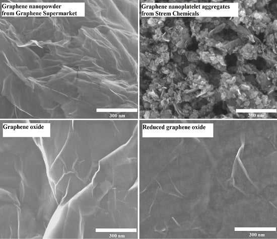
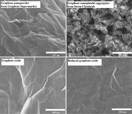
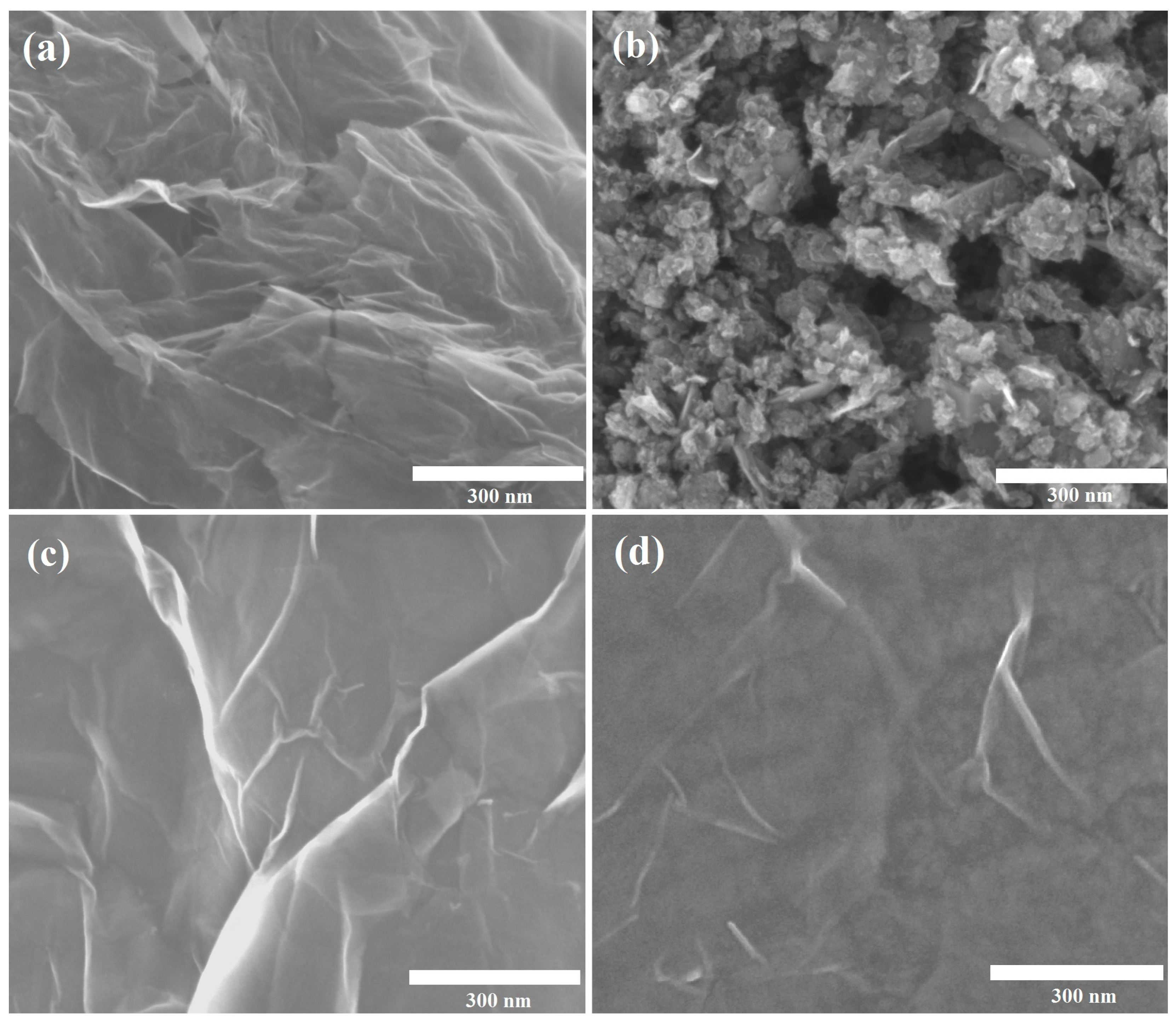
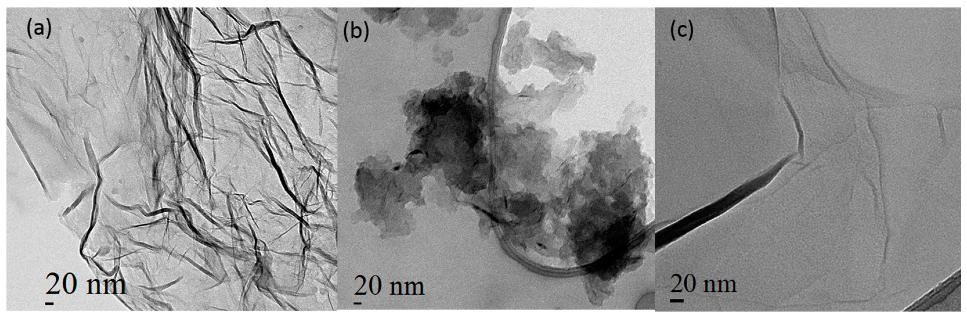
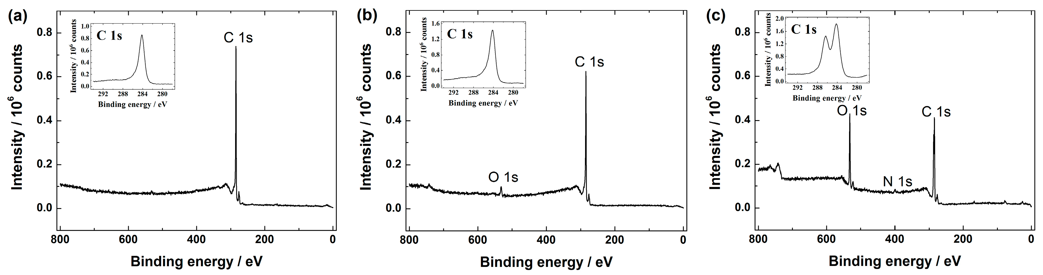
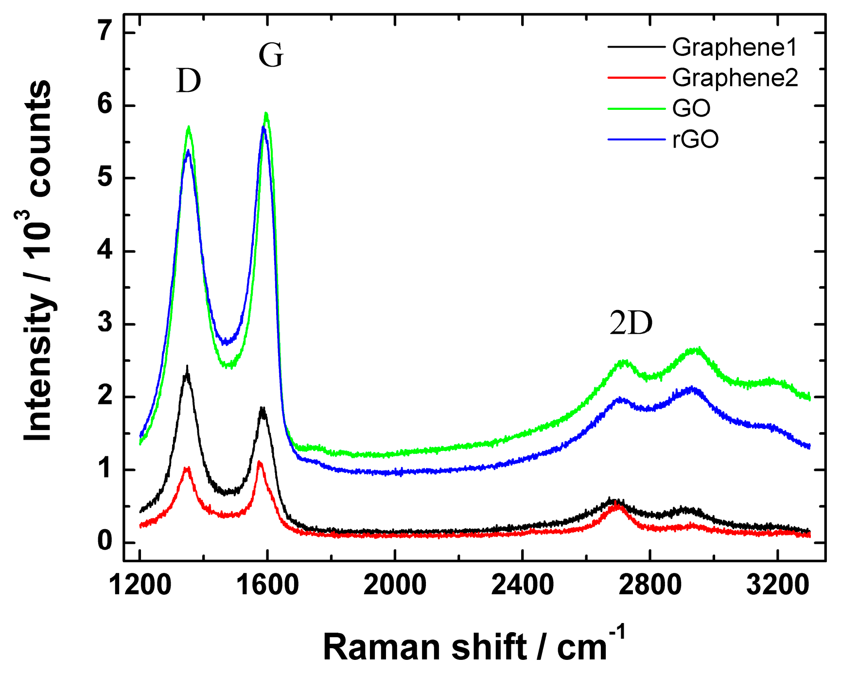
2.1. Surface Characterisation of Graphene-Family Nanomaterials

The surface morphology of the graphene-family nanomaterials used in this work was first investigated by scanning electron microscopy (SEM). As revealed in Figure 1, the graphene samples of graphene nanopowder, GO and rGO show typical graphene-like sheet morphology with folds and wrinkles. No notable differences could be observed between the samples of GO and rGO (Figure 1c,d) as both formed a thin, smooth, multilayer graphene film on the GC surface. The SEM image of GO is in good accordance with the results reported by Vikkisk et al. [37], where the synthesis of GO was performed by similar procedure as in this study. The SEM image of graphene nanopowder was slightly different (see Figure 1a), since the graphene sheets formed larger “fluffy” agglomerates and were not as well separated as in case of GO and rGO (see Figure 1c,d). However, the most distinct surface morphology was observed in case of graphene nanoplatelet aggregates (Figure 1b), where most of the material consisted of smaller, possibly multilayer, randomly oriented graphene flakes that were mixed with larger flakes. Similar features about this graphene-based material was seen by Shypunov et al. [50]. It is also important to note that, in a dry state, graphene nanopowder and graphene nanoplatelet aggregates tend to curl into micrometric rings or seriously aggregate (see additional SEM images of Graphene1 and Graphene2 in Figures S1 and S2, respectively, in Supplementary Material).
In order to get some further insight, the surface morphology of graphene nanopowder (from Graphene Supermarket), graphene nanoplatelet aggregates (from Strem Chemicals) and rGO was studied by transmission electron microscopy (TEM). Similar to SEM analysis, TEM also provided similar morphologies for the commercial graphene nanomaterial samples. Nevertheless more details are available at the nanoscale, especially in the case of the graphene nanoplatelet sample from Strem Chemicals illustrated in Figure 2b. Here one clearly observes that individual platelet size of ~30 nm can be observed. These nanoplatelets tend to agglomerate, which might explain the “fluffy” structure. On the other hand, the graphene nanopowder from Graphene Supermarket (see Figure 2a) shows a single layer of graphene with many nanometre thick creases contrary to the rGO sample (see Figure 2c), where a single layer of graphene with a smaller amount of creasing is visible. In any case, all the three samples presented here, exhibit differences in surface morphology.
Graphene-based materials were further analysed by XPS. The XPS survey spectra show the presence of C 1s in all the graphene samples (see Figure 3), including GO (data not shown).
The high resolution C 1s peak for all these materials was centred at ca. 284.5 eV and it is well-known that this corresponds to the sp2 carbon. Additionally, the XPS spectra of GO (data not displayed) and rGO (see Figure 3c) revealed another peak around 286.4 eV presumably attributed to the C-O species (e.g., hydroxyl and epoxy groups) [37,47,51,52]. According to the literature, GO should also consist carboxylic and carbonyl groups, which decorate the edge sites, whereas hydroxyl and epoxy groups are present on the basal plane of a GO sheet [15,30]. As can be seen from Figure 3a,b, mainly a C 1s peak in graphene nanopowder (Graphene Supermarket) and graphene nanoplatelet aggregates (Strem Chemicals) is shown, whereas the O 1s peak in both samples is rather negligible referring to a very low oxygen content, which in turn gives a very low O/C ratio. For example, in case of graphene nanoplatelet aggregates (Strem Chemicals) the total oxygen content was ca. 2 at.%, giving the O/C ratio about 0.02. This feature is in good agreement with the specification data of graphene nanopowder and graphene nanoplatelet aggregates given by Graphene Supermarket and Strem Chemicals, respectively. Based on the literature, the low O/C ratio refers to the near true nature of graphene [53]. The main difference between GO and rGO is that GO is with higher oxygen content than rGO [54,55]. Even though the reduction of GO should supposedly remove the oxygen-containing species from the rGO surface in order to restore some unique properties of pristine graphene [15], it has been shown that some amount of oxygen still remains in the sample of rGO [24,28,38,52,56,57]. In this study, according to the XPS survey spectra of rGO (see Figure 3c), the O 1s peak of rGO have been declined compared with the XPS spectra of GO (data not shown), revealing that part of the C-O functionalities on the surface of GO have been reduced. More specifically, the surface oxygen content was ca. 25 at.% and 19 at.%, which in turn gives a O/C ratio of ca. 0.3 and 0.2 in case of GO and rGO samples, respectively. This is also consistent with the literature data [52,58]. Based on these observations, we may conclude that the hydrazine treatment results in a limited reduction of GO, since oxygen-containing functionalities still exist in the final product and it is clear that the rGO material synthesised in this work is only partially reduced graphene oxide. However, according to the literature this result is rather expected [15,51,52,59]. Additionally, the XPS survey spectra of rGO revealed a small N 1s peak (see Figure 3). In more specific, the nitrogen content of 2 at.% was estimated by XPS, suggesting that some amount of nitrogen may be present due to the hydrazine treatment [28]. This feature is in good agreement with the literature [52], where a similar synthesis procedure was used to obtain rGO.
Figure 4 shows Raman spectra of graphene nanopowder (from Graphene Supermarket), graphene nanoplatelet aggregates (from Strem Chemicals), GO and rGO.
In all cases, the low-energy part of Raman spectrum revealed a D (at ca. 1352 cm−1) and G peak (at ca. 1582 cm−1). It is well-known that the integrated intensity ratio of the defect D band to the G band (ID/IG ratio) is used to assess the extent of structural disorders or defects in the studied materials: the smaller the ID/IG value of the ordered structure, the smaller amount of defects or edge sites are present in the material. In this study, the ID/IG ratio of graphene nanopowder (from Graphene Supermarket), graphene nanoplatelet aggregates (from Strem Chemicals), GO and rGO were 0.92, 0.98, 1.46 and 1.71, respectively. These results suggest a higher level of disorder of the graphene layers and increased number of defects in rGO and GO samples compared with Graphene1 and Graphene2 materials. According to the literature, the ID/IG value of GO varied from 0.83 to 1.93 [58,60], therefore the results obtained in the current study are in compliance with the reported data. In addition, a small increase of ID/IG upon GO reduction was observed, which is in good agreement with the literature [52]. In addition, Hayes et al. claimed that using hydrazine for GO reduction, the ID/IG ratio does not change or changes only a little compared with the ID/IG ratio of GO after reduction [61]. Therefore, the increase in ID/IG value shows that the GO reduction process might somewhat damage the structure of rGO generating more defects, but as can be seen from SEM images (Figure 1), no significant change in surface morphology before and after reduction of GO was observed.

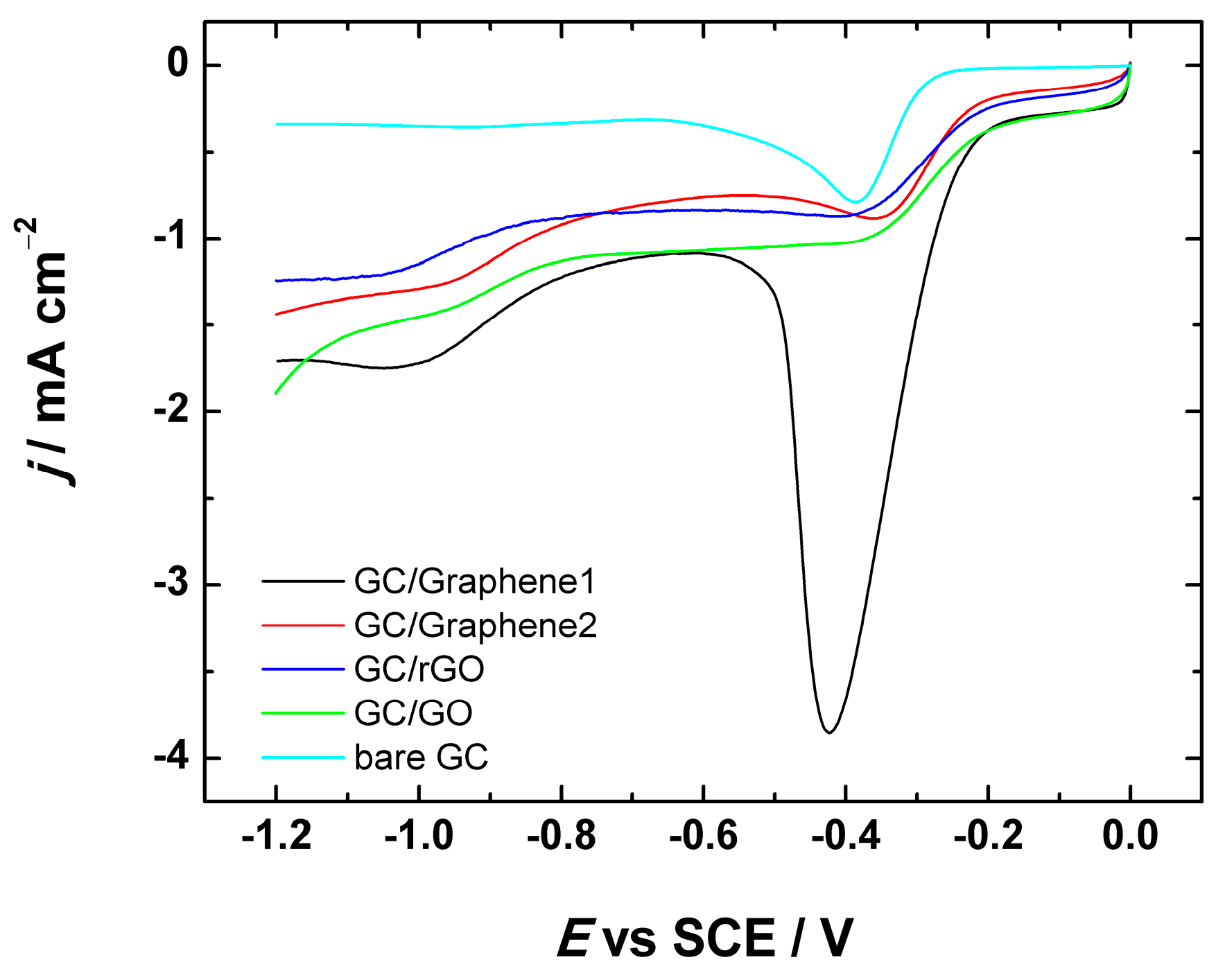
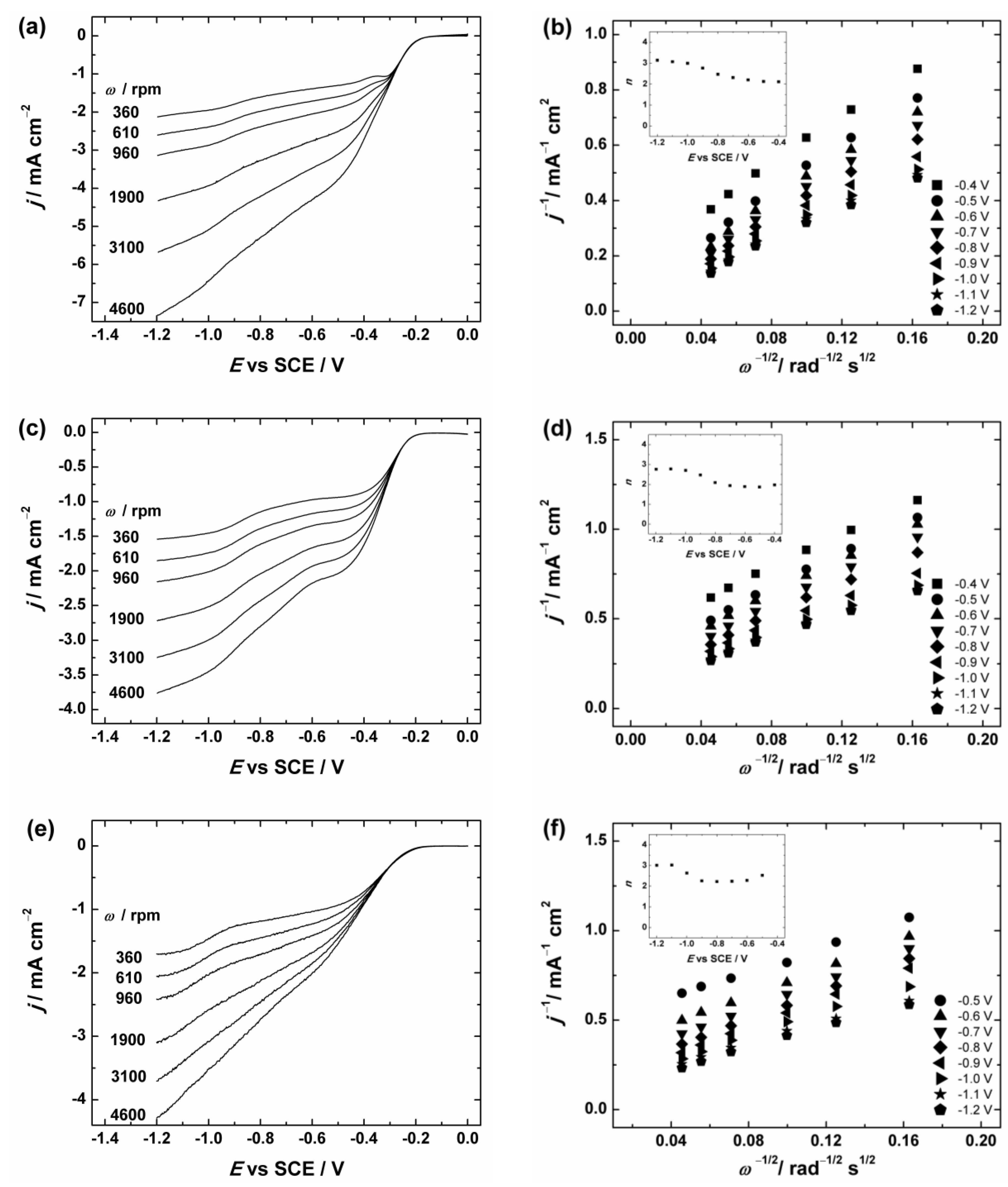
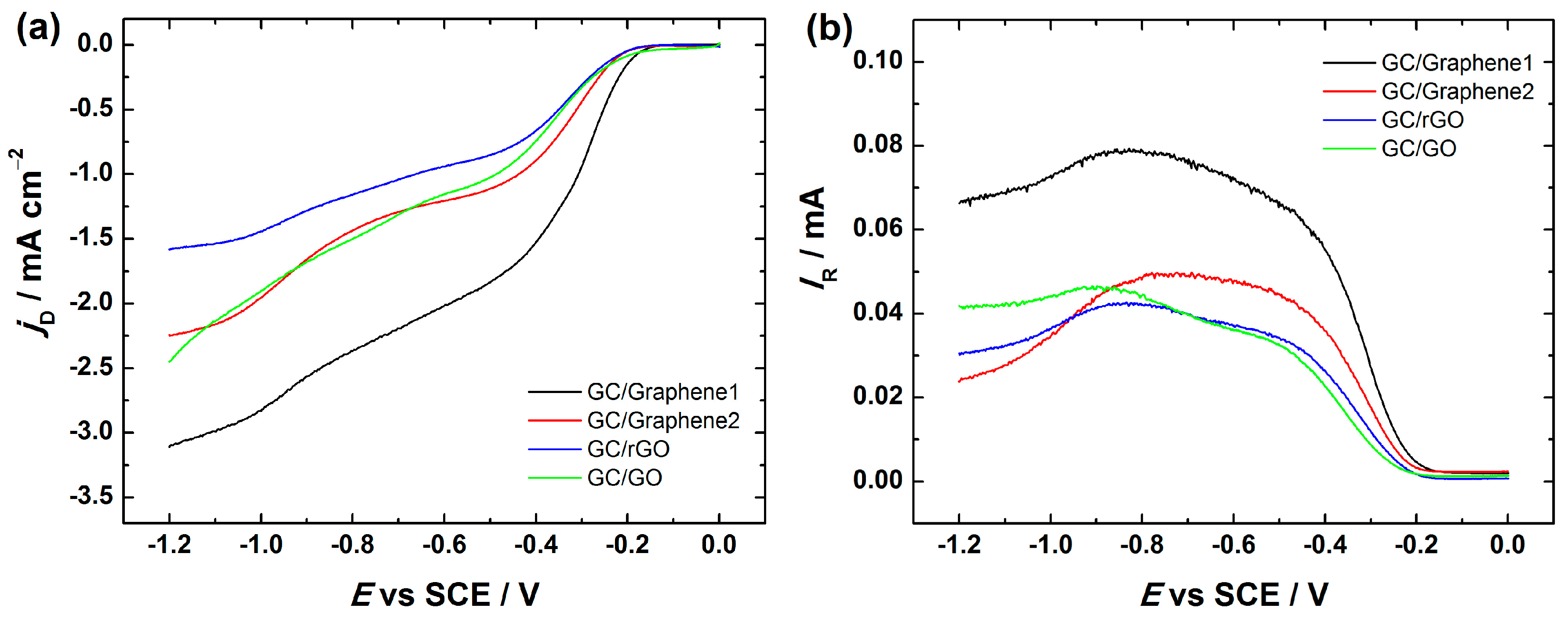
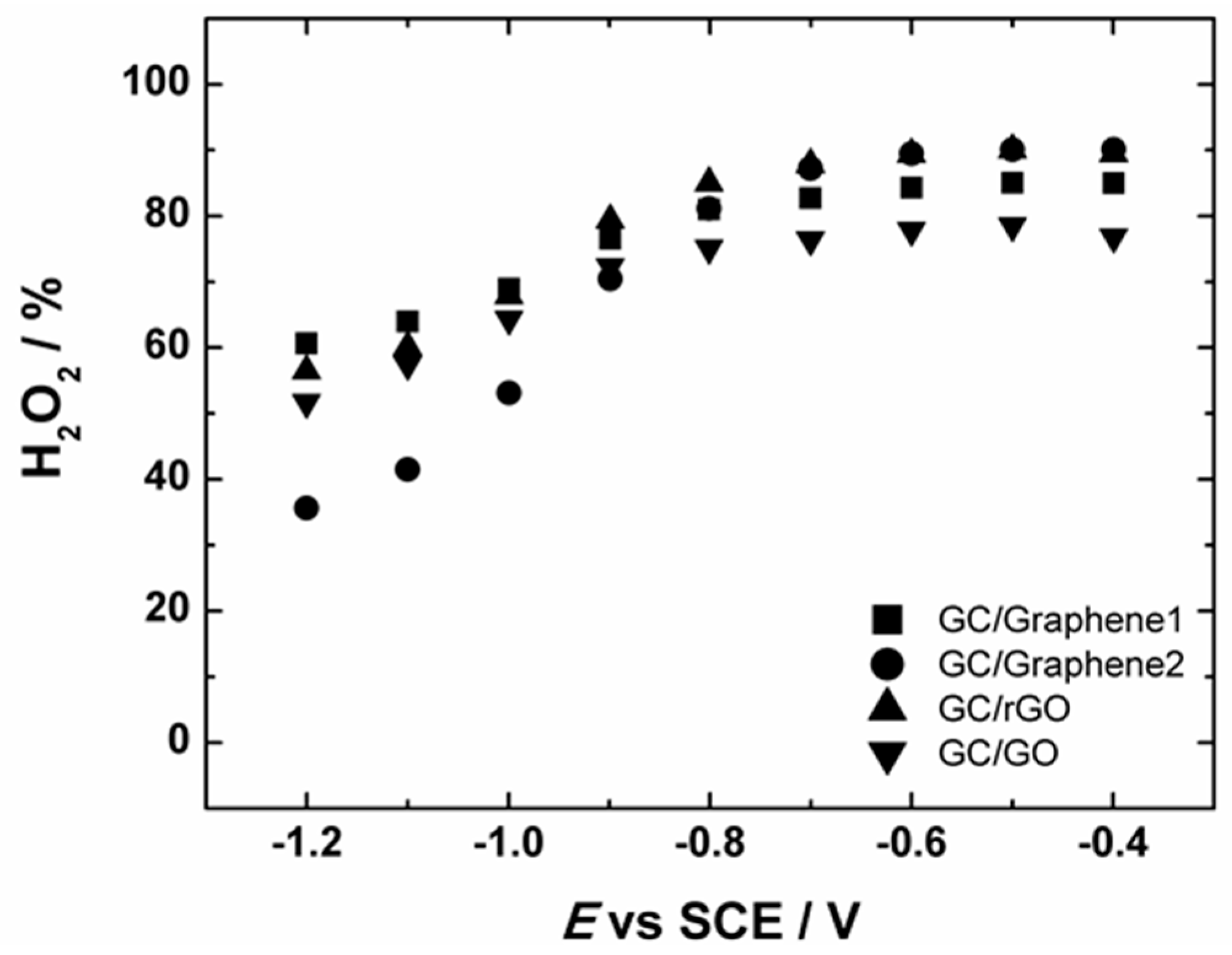
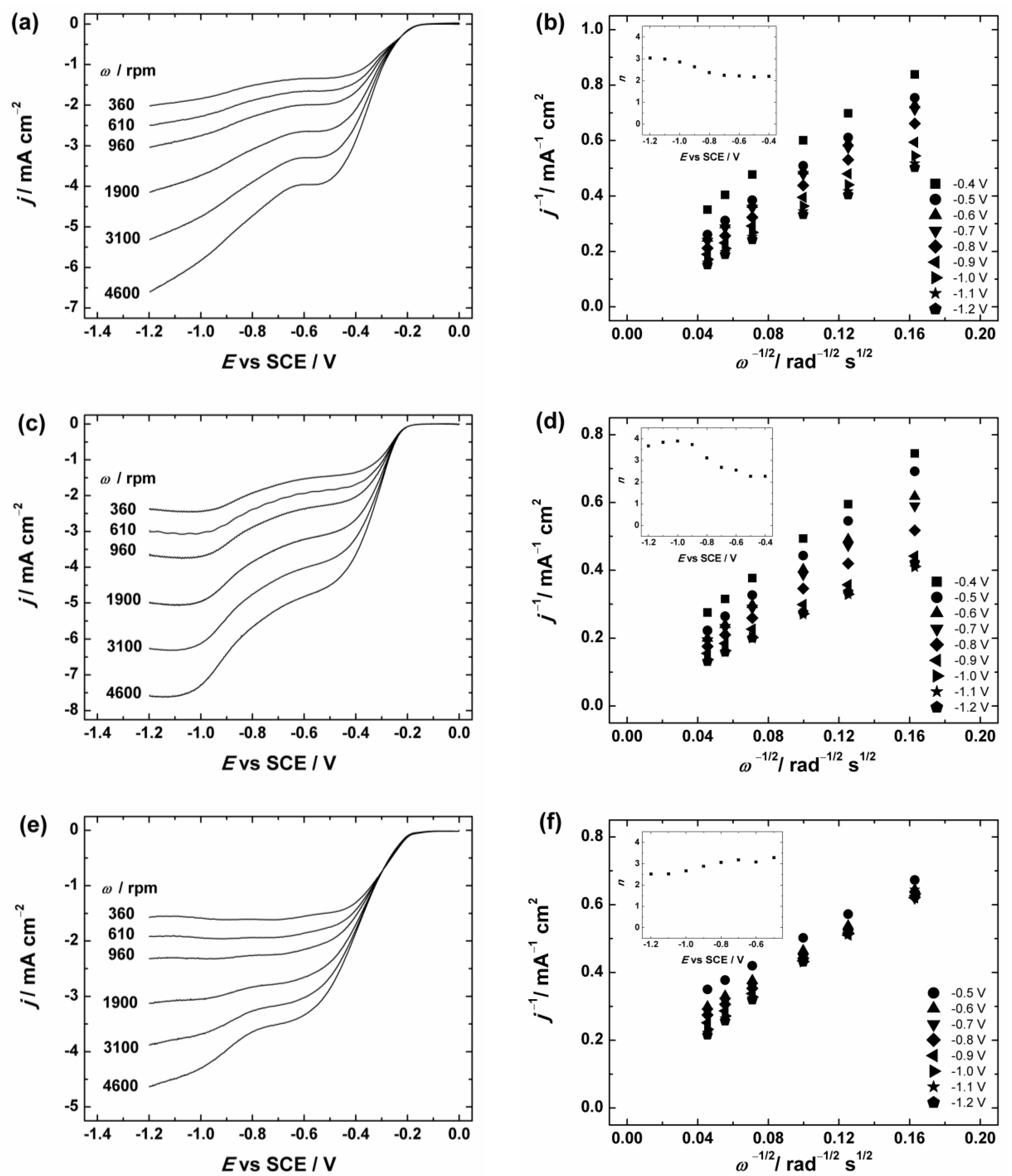
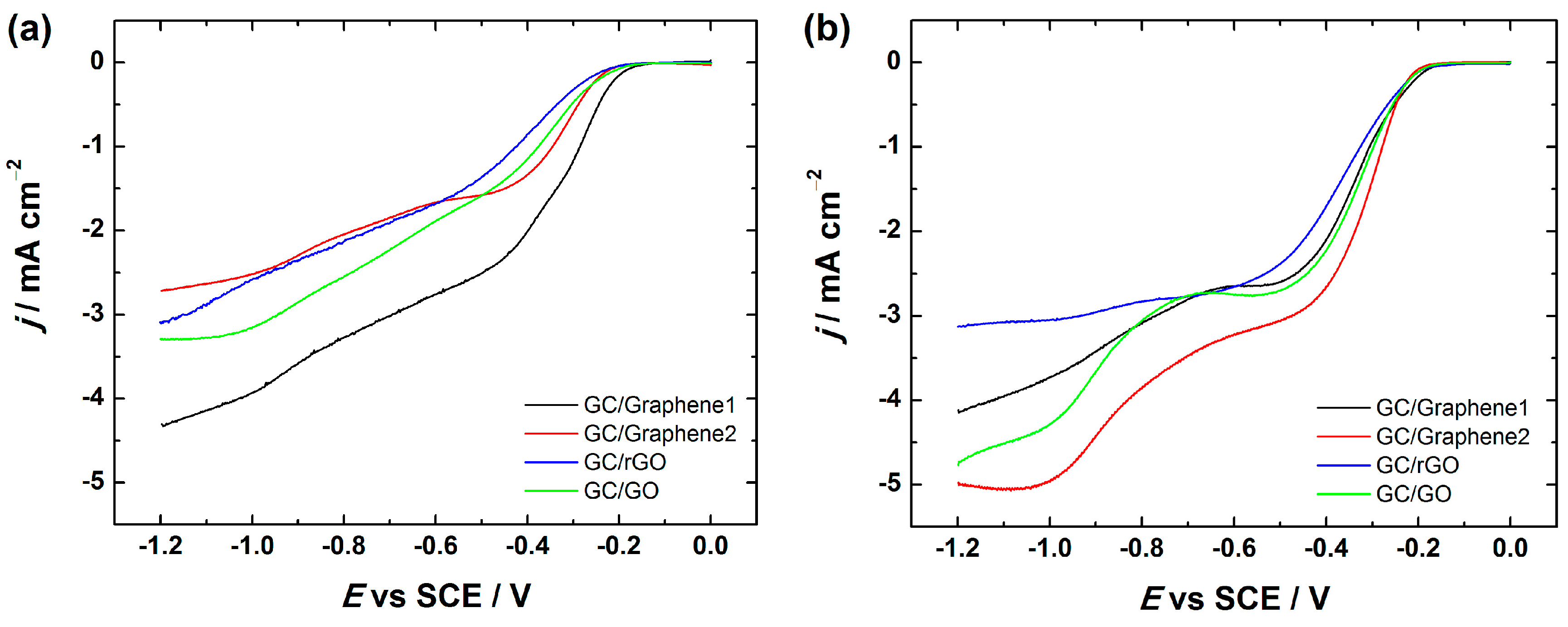
2.2. Oxygen Reduction Reaction on Graphene-Based Nanomaterials

To evaluate the electrocatalytic performance of graphene-based electrodes in alkaline media (O2-saturated 0.1 M KOH), various techniques e.g., linear sweep voltammetry (LSV), the rotating disc electrode (RDE) and rotating ring-disc electrode (RRDE) methods were used. For comparison purposes, GO-modified GC electrode was also tested. When considering the applications of graphene-based materials in fuel cells, an ionomer is needed in order to form ionic transport pathways between the reaction sites in the catalyst layer and the membrane e.g., in anion exchange membrane fuel cells [62]. On the other hand, ionomer is also considered as a binder, which should enhance the adhesion of catalyst particles to the working electrode surface and therefore it has been used as an additive in the catalyst ink formulation [63]. Therefore in this study the graphene-coated GC electrodes were first prepared using the catalyst ink suspension in 2-propanol containing OH ionomer. In order to investigate the electrochemical behaviour of GO and graphene-based electrodes towards the ORR, LSV measurements were performed (see Figure 5).
As can be seen from Figure 5, the LSV curves of GO, Graphene1, Graphene2 and rGO-modified GC electrodes exhibited two reduction peaks, which is indicative of a predominant two-electron O2 reduction pathway. Since the ORR electrocatalytic activity of bare GC has been thoroughly studied, some similarities between graphene-based substrates and bare GC can be seen. Namely, according to the literature, bare GC exhibits also two reduction peaks (at about −0.4 and −0.9 V vs. SCE) in alkaline medium [41,64,65,66], which is in accordance with this study (see Figure 5). The presence of two reduction peaks indicates that the ORR undergoes two processes, both attributed to the two-electron reduction of O2 to HO2. It is believed that the ORR on GC is catalysed by the native quinone-type groups present on the GC surface [67,68,69]. However, it is important to note that for all studied materials, the current density values are higher as compared to that of bare GC (see Figure 5) indicating a better electrocatalytic activity for ORR on the graphene-based material, which is probably caused by a higher surface area of the catalyst materials. Typical LSV curves of Graphene1, Graphene2, rGO and GO-modified GC electrodes registered at different scan rates (ν = 20–500 mV·s−1) are presented in Figure S2. As can be seen from the inset of Figure S2, there is a linear relationship between the peak current density and the square root of scan rate (ν1/2), which is rather expected result for the electroactive species diffusing from solution.
To further investigate the ORR activity, the graphene-based materials in comparison with GO were tested by the RDE method in O2-saturated 0.1 M KOH solution. The RDE results of GC/Graphene1, GC/Graphene2, GC/rGO and GC/GO electrodes at different rotation rates are presented in Figure 6 and Figure S3. As expected, the current densities increase with increasing electrode rotation rate. In addition, the onset potential (the potential value at ca. 0.1 mA·cm−2) [70] was determined as ca. −0.2 V for GC/Graphene1, GC/Graphene2, GC/rGO and GC/GO electrodes. This value is higher than for example in case of bare GC (ca. −0.3 V [66]) indicating that the ORR process starts at a higher potential on all these materials than on bare GC, which is also consistent with the LSV results (see Figure 5).
To evaluate the number of transferred electrons (n) per O2 molecule the Koutecky–Levich (K-L) analysis (dependence of j1 on ω1/2) was performed using Equation (1):
1 j = 1 j k + 1 j d = 1 n F k C O 2 b 1 0.62 n F D O 2 2 / 3 v 1 / 6 C O 2 b ω 1 / 2
where j is the measured current density, jk and jd are the kinetic- and diffusion-limited current densities, respectively; n is the number of electrons exchanged; F is the Faraday constant (96485 C·mol−1); k is the electrochemical rate constant for ORR; C O 2 b is the concentration of O2 in bulk (1.2 × 10⁻⁶ mol·cm−3 in 0.1 M KOH [71]); D O 2 is the diffusion coefficient of oxygen (1.9 × 10⁻⁵ cm2·s−1 in 0.1 M KOH [71]); ν is the kinematic viscosity of the solution (0.01 cm2·s−1 [72]); and ω is the electrode rotation rate (rad·s−1). The K-L plots were analysed in the potential range between −0.4 and −1.2 V vs. SCE from the RDE data presented in Figure 6 and Figure S3. These K-L plots show that the process of O2 reduction is under the mixed kinetic–diffusion control in a large range of potentials (see Figure 6b,d,f and Figure S3b). The value of n was calculated from the slopes of the K-L plots and the dependence of n on the potential is presented in the insets of Figure 6b,d,f and Figure S3b. In Figure 6 the calculated n value for GC/Graphene1, GC/Graphene2, GC/rGO (see Figure 6) and GC/GO electrodes (see Figure S3) gradually increases with decreasing potential. In more specific, the n value is close to two at E > −0.8 V and increases up to three at more negative potentials. This indicates that the ORR process on GO and graphene-based materials at low overpotentials proceeds predominately via two-electron pathway with the production of HO2.
The RRDE technique provides further insight into the formation of peroxide intermediate. Figure 7 depicts the disc and ring current data for Graphene1, Graphene2 and rGO-coated GC electrodes at 960 rpm. The RRDE voltammetry curves of GC/GO electrodes are shown for comparison. In general, the RRDE results show the same trend as obtained by RDE. In all these electrodes the reduction of oxygen on the disc proceeds with concomitant HO2 oxidation on the Pt ring electrode.
The percentage yield of peroxide formation at the disc electrode was calculated from the RRDE data using Equation (2):
% H 2 O 2 = 2 I r N I d   +   I r N × 100 %
where Id and Ir, are the disc and ring current, respectively, and N is the collection efficiency (N = 0.25). In addition, the n value from the RRDE results was calculated according to Equation (3):
n = 4 I d I d + I r N  
The measured HO2 yield for Graphene1, Graphene2, GO and rGO-modified GC electrodes started to decrease from ca. −0.8 V (see Figure 8). This is also consistent with the n values obtained from the RRDE measurements, indicating that the n value slightly increased up to three (see Figure S4). In case of Graphene1, Graphene2, rGO and GO-based GC electrodes, the value of n reaches ca. 3 at more negative potentials, demonstrating that part of the produced HO2 can be further reduced to OH, which is also supported by the decrease in the ring current (see Figure 7b). This is in good agreement with the literature data suggesting that on graphene-based materials the reduction of HO2 to OH takes place at higher overpotentials.
It is well-known that the graphene nanosheets are prone to agglomerate due to the van der Waals interaction yielding a multilayer graphene structure, which in turn leads to the loss of the electrocatalytic activity for ORR. Therefore, it was of special interest to study the ORR by RDE on GO and graphene-based materials using different solvent, in more specific, N,N-dimethylformamide (DMF), for the catalyst ink preparation. The obtained RDE results and the K-L plots of O2 reduction for GC/Graphene1, GC/Graphene2 and GC/rGO are presented in Figure 9, whereas the RDE voltammetry curves and K-L plots of GC/GO electrodes are depicted in Figure S5. As can be seen from Figure 9 and Figure S5, the dependence of reduction current on the electrode rotation rate exists leading to an increased current density values. In addition, the RDE voltammetry curves on graphene-based electrodes exhibit two reduction waves consistent with the literature [44]. Moreover, the value of n is between two and three in case of GC/Graphene1 and GC/rGO, but even higher in case of GC/Graphene2 and GC/GO at higher potentials (see Figure 9 and Figure S5). Higher electron transfer number at high overpotentials on graphene-based electrodes has been also reported in the literature [35,73,74,75].
Figure 10 compares the RDE voltammetry curves of oxygen reduction at GO and different graphene-based electrodes including the ones prepared using 2-propanol containing OH ionomer as well as DMF in the catalyst ink preparation. Interestingly, when DMF was used as a dispersion medium for electrode preparation, the onset potential of the ORR remained the same (−0.2 V), which is in good agreement with the literature [35,37], but the current density values were higher for GC/Graphene2, GC/rGO and GC/GO electrodes compared with the electrodes prepared using 2-propanol containing OH ionomer (Figure 10). Interestingly, the reduction current density values were less affected in the case of GC/Graphene1. On the basis of these results, it might be suggested that the electrochemical behaviour of the GC/Graphene1 electrode towards the ORR does not greatly depend on the OH ionomer, whereas the OH ionomer inhibits the ORR rate of GC/Graphene2, GC/rGO and GC/GO electrodes.
Unfortunately, the reason for this inhibiting effect remains unclear, but it could be considered that the inhibition of the ORR kinetics might be caused by the interaction between the OH ionomer and GC/Graphene2, GC/rGO and GC/GO surface, which results in some blocking of the catalytic sites of the graphene-based materials that are responsible for the ORR activity.
Even though the OH ionomer inhibited the ORR on the graphene-based materials studied (except Graphene1), the electrodes prepared in DMF exhibited a good electrocatalytic effect in alkaline media. This clearly demonstrates that none of these graphene-based materials is so-called “true/pristine graphene”, since according to the literature a defect-free graphene exposing mostly the basal plane surface is rather inactive for ORR [19,41,45]. However, if edge sites have been introduced into basal plane graphene nanosheet on purpose [76], a significant enhancement in the ORR electrocatalytic activity can be observed. Notwithstanding, even less-than-perfect layers of graphene can be used in certain electrochemical applications including electrocatalyst supports for fuel cells [15].
The enhanced ORR activity of graphene-based electrodes compared with bulk carbon materials is explained by the high surface area, metal impurities, or defects of the graphene material (since defects usually contain edge sites along with the oxygen-containing groups and it is also well-known that edge sites are more electrocatalytically active than the basal plane towards the ORR) [9,43,77]. Interestingly, based on the XPS results and Raman studies, the oxygen content was very low and the ID/IG ratio was smaller in case of Graphene1 and Graphene2 samples compared with rGO and GO materials (see Section 2.1), but yet these two commercially available graphene materials (Graphene1 and Graphene2) exhibited high electrocatalytic activity for ORR. First, it should be noted that the ORR results obtained with Graphene2 are in good accordance with the literature [50]. However, to the best of our knowledge, there are no reports about the ORR studies on Graphene1 (graphene nanopowder purchased from Graphene Supermarket) in alkaline solution and it is rather difficult to compare the results with the literature. Amongst other things, oxygen reduction on Graphene1 has been studied in acid solution, but the material did not show any electrocatalytic effect for ORR [78]. Therefore, it can be concluded that this material (Graphene1) is only active in alkaline solution. This is rather expected since it is well-known that carbon-based catalysts have better catalytic activity in alkaline than in acidic media. But still, the question remains why these materials (Graphene1 and Graphene2) show rather good electrocatalytic properties compared with rGO. One explanation might be that these materials may contain some metal impurities originated from the synthesis process, which might enhance the ORR process, since Pumera and co-workers have shown that ORR electrocatalysis on graphene-based surfaces is primarily caused by the metal impurities [48,49]. It should be noted that in order to confirm this statement, the energy dispersive X-ray spectroscopic (EDX) measurements were carried out with Graphene1 and Graphene2 samples. The EDX measurements detected a small amount of impurities (e.g., Mn, K, S, Mg and Na) in case of Graphene1, which might facilitate the ORR electrocatalytic activity on this material. However, the EDX analysis did not show any metal impurities in Graphene2, but since the detection limit of EDX is rather low, it might still be possible that traces of transition metals are also present in Graphene2. Another possible reason for the higher ORR activity of commercial graphene-based samples might be due to the wrinkles within the graphene material as can be seen by SEM and TEM (Section 2.1). Namely, it has been suggested that even though the resistance is increased slightly in case of wrinkled, rippled and crumpled graphene, a good conductivity of graphene is still maintained [79,80,81,82].
In case of rGO-based electrodes, it has been suggested that the first reduction process is probably redox mediated by the quinone-type functional groups on the rGO surface, whereas the presence of other oxygen-containing groups on rGO may catalyse the further reduction of HO2 at more negative potentials [47] as was also shown by the increased n values. Tang et al. [83] have studied the ORR on rGO-modified GC electrodes in alkaline medium and the results revealed that rGO possessed better electrocatalytic activity towards the ORR than bare GC. These results are in agreement with the current study. However, taking into account the values of current densities, the GC/rGO showed the poorest electrocatalytic activity for ORR as compared to the other graphene-based materials (GC/Graphene1, GC/Graphene2) and GC/GO electrode (see Figure 10). This is somewhat unexpected result since based on the Raman study, the rGO sample consisted more defects than other samples (see the ID/IG ratio in Section 2.1) indicating that presumably more edge sites for oxygen adsorption are exposed compared with the other graphene-based materials. However, based on the literature, it has been claimed, that an increase in the amount of edges does not necessarily lead to a higher ORR activity [70]. On the other hand, it has been claimed that not only the amount of oxygenated species, but also the type of carbon-oxygen functionalities present on the surface of graphene-based materials could be considered as an important factor in the ORR [43]. Therefore, according to the XPS study (see Section 2.1), it was seen that the oxygen content was lower in case of rGO compared with GO which might indicate that possible oxygen-containing groups, which are responsible for the ORR enhancement are removed from the GO surface during the reduction process of GO, which in turn explains the lower ORR activity of rGO than GO.

3. Materials and Methods

3.1. Preparation of Graphene-Based Electrodes

Two commercially available graphene samples, graphene nanoplatelet aggregates (specific surface area of 750 m2·g−1, Strem Chemicals, (Newburyport, MA., USA) and graphene nanopowder (Grade AO-1, specific surface area of 510 m2·g−1, Graphene Supermarket), and pre-synthesised graphene oxide (GO) and reduced graphene oxide (rGO) were used in this work. GO was synthesised by a modified Hummer’s method from graphite powder using natural graphite flakes as a starting material [37,84] and rGO was synthesised in a similar manner as described by Lima et al. [52,85]. A brief description about the synthesis of GO and rGO is given in Supplementary Material.
For the underlying substrate, glassy carbon (GC) electrodes were used. GC discs (GC-20SS, Tokai Carbon Japan) with the diameter of 5 mm and a geometric area (A) of 0.196 cm2 were pressed into Teflon holders and before coating with graphene suspension, the surface of GC was sequentially polished to a mirror finish with 1.0 and 0.3 µm of Al2O3 slurries (Buehler, Lake Bluff, IL, USA). The GC electrodes were ultrasonically cleaned in Milli-Q water (Millipore, Inc.) and 2-propanol (Sigma-Aldrich, Saint-Louis, MO, USA) for 5 min in order to remove the residues of the alumina slurries.
To fabricate the graphene-based working electrodes with a mass loading of 0.1 mg·cm−2, first, the catalyst suspension was prepared by dispersing 1 mg of catalyst material in a 1 mL of 2-propanol containing 0.05% of OH ionomer (AS-04, Tokuyama Corp., Tokyo, Japan) or in a 1 mL of N,N-dimethylformamide (DMF) followed by ultrasonication treatment. Thereafter, 20 µL aliquot of the suspension was pipetted onto the surface of freshly cleaned GC electrode followed by drying the working electrode at 60 °C. When graphene nanopowder from Graphene Supermarket, graphene nanoplatelet aggregates from Strem Chemicals, rGO and GO were used as a catalyst material, the modified GC electrodes were designated as follows: GC/Graphene1, GC/Graphene2, GC/rGO and GC/GO, respectively.

3.2. Electrochemical Measurements

Electrochemical experiments were performed in a three-electrode glass cell using an Autolab potentiostat/galvanostat PGSTAT30 (Eco Chemie B.V., Utrecht, The Netherlands) controlled with General Purpose Electrochemical System (GPES) software. Working electrodes were GO and graphene-coated GC electrodes. The reference electrode was a saturated calomel electrode (SCE) and a platinum wire was used as the counter electrode, which were separated from the solution by a Luggin capillary and a glass frit, respectively. All the potentials mentioned in this work are given with respect to SCE.
For the electrochemical measurements, linear sweep voltammetry (LSV), rotating disc electrode (RDE) method and rotating ring-disc electrode (RRDE) method were employed. The RDE measurements were conducted with an EDI101 rotator and a CTV101 speed control unit (Radiometer, Copenhagen, Denmark), whereas an interchangeable E6 series RRDE tip of GC disc-Pt ring, a AFMSRX rotator and MSRX speed controller (Pine Research Instrumentation, Grove City, PA, USA) were used for the RRDE experiments. The collection efficiency (N) was 0.25 as determined by the reduction of hexacyanoferrate(III). In case of the RRDE measurements, the Pt ring electrode was electrochemically cleaned before recording each polarisation curve by applying three potential cycles between −1.0 and 0.7 V at 100 mV·s−1 in order to improve the reliability in the determination of peroxide. The Pt ring electrode was kept under the potentiostatic control at 0.55 V vs. SCE for the peroxide detection.
The ORR polarisation curves were recorded in O2-saturated 0.1 M KOH solution (p.a. quality). For the preparation of the aqueous solutions, Milli-Q water was used. All the electrochemical experiments were carried out at room temperature (23 ± 1 °C) and all current densities were normalised to the geometric area of the GC electrode.

3.3. Surface Characterisation of Graphene-Based Samples

A high resolution scanning electron microscope (HR-SEM) Helios NanoLab 600 (FEI Company, Hillsboro, OR, USA) equipped with an energy-dispersive X-ray spectrometer (EDX) analyser INCA Energy 350 (Oxford Instruments, Abingdon, UK) was used for imaging and analysing the sample surfaces. Transmission electron microscopy (TEM) was employed to study in detail the morphological properties of various graphene-based samples. TEM measurements were performed on a TITAN 200 (FEI Company, Hillsboro, OR, USA) operating at 200 kV. Sample for TEM observation was prepared by sonication of the graphene samples in ethanol and placing a drop of this suspension on a carbon-coated TEM grid. In addition, these materials were characterised by micro-Raman spectrometer (inVia, Renishaw) applying a laser with 514 nm wavelength and 10% of maximum intensity. A silicon plate was used as a substrate for the Raman analysis. The elemental composition of graphene samples was studied by X–ray photoelectron spectroscopy (XPS) using 1.1 × 1.1 cm GC plates for the deposition of the graphene-based materials. The XPS measurements were carried out with a SCIENTA SES-100 spectrometer using an unmonochromated Mg Kα X-ray source (incident energy = 1253.6 eV), electron take-off angle 90° and source power of 300 W. The pressure in the analysis chamber was under 10−9 Torr. At the time the survey scan was collected, the energy range was from 0 to 800 eV, pass energy 200 eV and step size 0.5 eV. For high-resolution scans, the pass energy was 200 eV and step size 0.1 eV.

4. Conclusions

In this work, we have explored the electrocatalysis of the ORR on two commercially available graphene materials (graphene nanopowder from Graphene Supermarket and graphene nanoplatelet aggregates from Strem Chemicals) and on reduced graphene oxide (rGO). The catalyst suspension was prepared either in 2-propanol containing OH ionomer or in DMF to study the effect of ionomer on the electrocatalytic activity of these materials towards the ORR. In general, the graphene-based electrodes prepared from the suspension in DMF showed better ORR activity than those made using the suspensions in 2-propanol containing OH ionomer, referring to the inhibiting effect of the OH ionomer. However, the LSV, RDE and RRDE results revealed that the electrochemical reduction of oxygen at all studied materials followed a two-step ORR process with the formation of peroxide as an intermediate.

Supplementary Materials

The following are available online at https://www.mdpi.com/2073-4344/6/7/108/s1, Synthesis of GO and rGO; Figure S1: SEM images of: (a) graphene nanopowder (from Graphene Supermarket) and (b) graphene nanoplatelet aggregates (from Strem Chemicals); Figure S2: LSV results of O2 reduction on GC electrodes coated with: (a) graphene nanopowder (from Graphene Supermarket), (b) graphene nanoplatelet aggregates (from Strem Chemicals), (c) graphene oxide and (d) reduced graphene oxide. The electrodes were prepared using the catalyst ink suspension in 2-propanol containing OH ionomer. The LSVs were registered in O2-saturated 0.1 M KOH at different scan rates. The insets show the dependence of jp on ν1/2. Figure S3: (a) RDE voltammetry curves and (b) Koutecky–Levich plots for oxygen reduction on GC electrodes coated with graphene oxide in O2-saturated 0.1 M KOH. ω = 360–4600 rpm, ν = 10 mV·s−1. The electrode was prepared using the catalyst ink suspension in 2-propanol containing OH ionomer. The inset shows the potential dependence of n. Figure S4: Potential dependence of n for GC electrodes modified with graphene nanopowder from Graphene Supermarket (GC/Graphene1), graphene nanoplatelet aggregates from Strem Chemicals (GC/Graphene2), reduced graphene oxide (GC/rGO) and graphene oxide (GC/GO) in O2-saturated 0.1 M KOH. The electrodes were prepared using the catalyst ink suspension in 2-propanol containing OH ionomer. Data derived from Figure 7. Figure S5: (a) RDE voltammetry curves and (b) Koutecky–Levich plots for oxygen reduction on GC electrodes coated with graphene oxide in O2-saturated 0.1 M KOH. ω = 360–4600 rpm, ν = 10 mV·s−1. The inset shows the potential dependence of n. The electrode was prepared using the catalyst ink suspension in DMF.

Acknowledgments

This work was financially supported by institutional research funding (IUT20-16 and IUT2-24) of the Estonian Ministry of Education and Research. We gratefully acknowledge the financial support provided by the Estonian Research Council (Grant No. 9323). We would like to thank the Estonian Road Map Infrastructure project NAMUR. This research was also supported by the EU through the European Regional Development Fund (TK141 “Advanced materials and high-technology devices for energy recuperation systems”).

Author Contributions

Jaana Lilloja synthesised GO and rGO and carried out the ORR measurements on all the studied materials; Jaana Lilloja and Elo Kibena-Põldsepp analysed the data; Eduardo S.F. Cardoso and Gilberto Maia made substantial contributions to the GO and rGO synthesis procedures; Maido Merisalu, Protima Rauwel, Leonard Matisen and Ahti Niilisk performed the SEM, TEM, XPS and Raman spectroscopy measurements, respectively; Elo Kibena-Põldsepp wrote the paper; Maido Merisalu, Protima Rauwel, Leonard Matisen, Ahti Niilisk, Gilberto Maia, Väino Sammelselg and Kaido Tammeveski made substantial contributions to writing of this manuscript; and all the authors participated in discussions of the research.

Conflicts of Interest

The authors declare no conflict of interest.

References

  1. Novoselov, K.S.; Geim, A.K.; Morozov, S.V.; Jiang, D.; Zhang, Y.; Dubonos, S.V.; Grigorieva, I.V.; Firsov, A.A. Electric field effect in atomically thin carbon films. Science 2004, 306, 666–669. [Google Scholar] [CrossRef] [PubMed]
  2. Nehra, A.; Singh, K.P. Current trends in nanomaterial embedded field effect transistor-based biosensor. Biosens. Bioelectron. 2015, 74, 731–743. [Google Scholar] [CrossRef] [PubMed]
  3. Geim, A.K.; Novoselov, K.S. The rise of graphene. Nat. Mater. 2007, 6, 183–191. [Google Scholar] [CrossRef] [PubMed]
  4. Lee, C.; Wei, X.; Kysar, J.W.; Hone, J. Measurement of the elastic properties and intrinsic strength of monolayer graphene. Science 2008, 321, 385–388. [Google Scholar] [CrossRef] [PubMed]
  5. Novoselov, K.S.; Jiang, D.; Schedin, F.; Booth, T.J.; Khotkevich, V.V.; Morozov, S.V.; Geim, A.K. Two-dimensional atomic crystals. Proc. Nat. Acad. Sci. USA 2005, 102, 10451–10453. [Google Scholar] [CrossRef] [PubMed]
  6. Stankovich, S.; Dikin, D.A.; Dommett, G.H.B.; Kohlhaas, K.M.; Zimney, E.J.; Stach, E.A.; Piner, R.D.; Nguyen, S.T.; Ruoff, R.S. Graphene-based composite materials. Nature 2006, 442, 282–286. [Google Scholar] [CrossRef] [PubMed]
  7. Iwan, A.; Malinowski, M.; Pasciak, G. Polymer fuel cell components modified by graphene: Electrodes, electrolytes and bipolar plates. Renew. Sustain. Energy Rev. 2015, 49, 954–967. [Google Scholar] [CrossRef]
  8. Randviir, E.P.; Brownson, D.A.C.; Banks, C.E. A decade of graphene research: Production, applications and outlook. Mater. Today 2014, 17, 426–432. [Google Scholar] [CrossRef]
  9. Hou, J.; Shao, Y.; Ellis, M.W.; Moore, R.B.; Yi, B. Graphene-based electrochemical energy conversion and storage: Fuel cells, supercapacitors and lithium ion batteries. Phys. Chem. Chem. Phys. 2011, 13, 15384–15402. [Google Scholar] [CrossRef] [PubMed]
  10. Lawal, A.T. Synthesis and utilisation of graphene for fabrication of electrochemical sensors. Talanta 2015, 131, 424–443. [Google Scholar] [CrossRef] [PubMed]
  11. Chung, C.; Kim, Y.K.; Shin, D.; Ryoo, S.R.; Hong, B.H.; Min, D.H. Biomedical applications of graphene and graphene oxide. Acc. Chem. Res. 2013, 46, 2211–2224. [Google Scholar] [CrossRef] [PubMed]
  12. Pumera, M. Graphene in biosensing. Mater. Today 2011, 14, 308–315. [Google Scholar] [CrossRef]
  13. Brownson, D.A.C.; Kampouris, D.K.; Banks, C.E. An overview of graphene in energy production and storage applications. J. Power Sources 2011, 196, 4873–4885. [Google Scholar] [CrossRef]
  14. Mahmood, N.; Zhang, C.; Yin, H.; Hou, Y. Graphene-based nanocomposites for energy storage and conversion in lithium batteries, supercapacitors and fuel cells. J. Mater. Chem. A 2014, 2, 15–32. [Google Scholar] [CrossRef]
  15. Haag, D.; Kung, H.H. Metal free graphene based catalysts: A review. Top. Catal. 2014, 57, 762–773. [Google Scholar] [CrossRef]
  16. Zhu, Y.; Murali, S.; Cai, W.; Li, X.; Suk, J.W.; Potts, J.R.; Ruoff, R.S. Graphene and graphene oxide: Synthesis, properties, and applications. Adv. Mater. 2010, 22, 3906–3924. [Google Scholar] [CrossRef] [PubMed]
  17. Antolini, E. Graphene as a new carbon support for low-temperature fuel cell catalysts. Appl. Catal. B Environ. 2012, 123, 52–68. [Google Scholar] [CrossRef]
  18. Novoselov, K.S.; Fal’ko, V.I.; Colombo, L.; Gellert, P.R.; Schwab, M.G.; Kim, K. A roadmap for graphene. Nature 2012, 490, 192–200. [Google Scholar] [CrossRef] [PubMed]
  19. Brownson, D.A.C.; Banks, C.E. The electrochemistry of CVD graphene: Progress and prospects. Phys. Chem. Chem. Phys. 2012, 14, 8264–8281. [Google Scholar] [CrossRef] [PubMed]
  20. Thakur, S.; Karak, N. Alternative methods and nature-based reagents for the reduction of graphene oxide: A review. Carbon 2015, 94, 224–242. [Google Scholar] [CrossRef]
  21. Aunkor, M.T.H.; Mahbubul, I.M.; Saidur, R.; Metselaar, H.S.C. Deoxygenation of graphene oxide using household baking soda as a reducing agent: A green approach. RSC Adv. 2015, 5, 70461–70472. [Google Scholar] [CrossRef]
  22. Park, S.; An, J.; Potts, J.R.; Velamakanni, A.; Murali, S.; Ruoff, R.S. Hydrazine-reduction of graphite- and graphene oxide. Carbon 2011, 49, 3019–3023. [Google Scholar] [CrossRef]
  23. Huang, X.; Zeng, Z.; Fan, Z.; Liu, J.; Zhang, H. Graphene-based electrodes. Adv. Mater. 2012, 24, 5979–6004. [Google Scholar] [CrossRef] [PubMed]
  24. Pei, S.; Cheng, H.-M. The reduction of graphene oxide. Carbon 2012, 50, 3210–3228. [Google Scholar] [CrossRef]
  25. Chua, C.K.; Pumera, M. Reduction of graphene oxide with substituted borohydrides. J. Mater. Chem. A 2013, 1, 1892–1898. [Google Scholar] [CrossRef]
  26. Zhou, M.; Wang, Y.; Zhai, Y.; Zhai, J.; Ren, W.; Wang, F.; Dong, S. Controlled synthesis of large-area and patterned electrochemically reduced graphene oxide films. Chem. Eur. J. 2009, 15, 6116–6120. [Google Scholar] [CrossRef] [PubMed]
  27. Guo, H.-L.; Wang, X.-F.; Qian, Q.-Y.; Wang, F.-B.; Xia, X.-H. A green approach to the synthesis of graphene nanosheets. ACS Nano 2009, 3, 2653–2659. [Google Scholar] [CrossRef] [PubMed]
  28. Stankovich, S.; Dikin, D.A.; Piner, R.D.; Kohlhaas, K.A.; Kleinhammes, A.; Jia, Y.; Wu, Y.; Nguyen, S.T.; Ruoff, R.S. Synthesis of graphene-based nanosheets via chemical reduction of exfoliated graphite oxide. Carbon 2007, 45, 1558–1565. [Google Scholar] [CrossRef]
  29. Marcano, D.C.; Kosynkin, D.V.; Berlin, J.M.; Sinitskii, A.; Sun, Z.; Slesarev, A.; Alemany, L.B.; Lu, W.; Tour, J.M. Improved synthesis of graphene oxide. ACS Nano 2010, 4, 4806–4814. [Google Scholar] [CrossRef] [PubMed]
  30. Dreyer, D.R.; Park, S.; Bielawski, C.W.; Ruoff, R.S. The chemistry of graphene oxide. Chem. Soc. Rev. 2010, 39, 228–240. [Google Scholar] [CrossRef] [PubMed]
  31. Le, T.X.H.; Bechelany, M.; Champavert, J.; Cretin, M. A highly active based graphene cathode for the electro-Fenton reaction. RSC Adv. 2015, 5, 42536–42539. [Google Scholar] [CrossRef]
  32. Zhu, C.; Dong, S. Recent progress in graphene-based nanomaterials as advanced electrocatalysts towards oxygen reduction reaction. Nanoscale 2013, 5, 1753–1767. [Google Scholar] [CrossRef] [PubMed]
  33. Trogadas, P.; Fuller, T.F.; Strasser, P. Carbon as catalyst and support for electrochemical energy conversion. Carbon 2014, 75, 5–42. [Google Scholar] [CrossRef]
  34. Qu, L.; Liu, Y.; Baek, J.-B.; Dai, L. Nitrogen-doped graphene as efficient metal-free electrocatalyst for oxygen reduction in fuel cells. ACS Nano 2010, 4, 1321–1326. [Google Scholar] [CrossRef] [PubMed]
  35. Sheng, Z.-H.; Shao, L.; Chen, J.-J.; Bao, W.-J.; Wang, F.-B.; Xia, X.-H. Catalyst-free synthesis of nitrogen-doped graphene via thermal annealing graphite oxide with melamine and its excellent electrocatalysis. ACS Nano 2011, 5, 4350–4358. [Google Scholar] [CrossRef] [PubMed]
  36. Liang, Y.; Li, Y.; Wang, H.; Zhou, J.; Wang, J.; Regier, T.; Dai, H. Co3O4 nanocrystals on graphene as a synergistic catalyst for oxygen reduction reaction. Nat. Mater. 2011, 10, 780–786. [Google Scholar] [CrossRef] [PubMed]
  37. Vikkisk, M.; Kruusenberg, I.; Joost, U.; Shulga, E.; Kink, I.; Tammeveski, K. Electrocatalytic oxygen reduction on nitrogen-doped graphene in alkaline media. Appl. Catal. B-Environ. 2014, 147, 369–376. [Google Scholar] [CrossRef]
  38. Kruusenberg, I.; Mondal, J.; Matisen, L.; Sammelselg, V.; Tammeveski, K. Oxygen reduction on graphene-supported MN4 macrocycles in alkaline media. Electrochem. Commun. 2013, 33, 18–22. [Google Scholar] [CrossRef]
  39. Yang, Z.; Yao, Z.; Li, G.; Fang, G.; Nie, H.; Liu, Z.; Zhou, X.; Chen, X.; Huang, S. Sulfur-doped graphene as an efficient metal-free cathode catalyst for oxygen reduction. ACS Nano 2012, 6, 205–211. [Google Scholar] [CrossRef] [PubMed]
  40. Randviir, E.P.; Brownson, D.A.C.; Gomez-Mingot, M.; Kampouris, D.K.; Iniesta, J.; Banks, C.E. Electrochemistry of Q-graphene. Nanoscale 2012, 4, 6470–6480. [Google Scholar] [CrossRef] [PubMed]
  41. Kibena, E.; Marandi, M.; Sammelselg, V.; Tammeveski, K.; Jensen, B.B.E.; Mortensen, A.B.; Lillethorup, M.; Kongsfelt, M.; Pedersen, S.U.; Daasbjerg, K. Electrochemical behaviour of HOPG and CVD-grown graphene electrodes modified with thick anthraquinone films by diazonium reduction. Electroanalysis 2014, 26, 2619–2630. [Google Scholar] [CrossRef]
  42. Shahgaldi, S.; Hamelin, J. Improved carbon nanostructures as a novel catalyst support in the cathode side of PEMFC: A critical review. Carbon 2015, 94, 705–728. [Google Scholar] [CrossRef]
  43. Randviir, E.P.; Banks, C.E. The oxygen reduction reaction at graphene modified electrodes. Electroanalysis 2014, 26, 76–83. [Google Scholar] [CrossRef]
  44. Wang, D.-W.; Su, D. Heterogeneous nanocarbon materials for oxygen reduction reaction. Energy Environ. Sci. 2014, 7, 576–591. [Google Scholar] [CrossRef]
  45. Kibena, E.; Mooste, M.; Kozlova, J.; Marandi, M.; Sammelselg, V.; Tammeveski, K. Surface and electrochemical characterisation of CVD grown graphene sheets. Electrochem. Commun. 2013, 35, 26–29. [Google Scholar] [CrossRef]
  46. Jahan, M.; Bao, Q.; Loh, K.P. Electrocatalytically active graphene-porphyrin MOF composite for oxygen reduction reaction. J. Am. Chem. Soc. 2012, 134, 6707–6713. [Google Scholar] [CrossRef] [PubMed]
  47. Bikkarolla, S.K.; Cumpson, P.; Joseph, P.; Papakonstantinou, P. Oxygen reduction reaction by electrochemically reduced graphene oxide. Faraday Discuss. 2014, 173, 415–428. [Google Scholar] [CrossRef] [PubMed]
  48. Wang, L.; Chua, C.K.; Khezri, B.; Webster, R.D.; Pumera, M. Remarkable electrochemical properties of electrochemically reduced graphene oxide towards oxygen reduction reaction are caused by residual metal-based impurities. Electrochem. Commun. 2016, 62, 17–20. [Google Scholar] [CrossRef]
  49. An Wong, C.H.; Sofer, Z.; Kubešová, M.; Kučera, J.; Matějková, S.; Pumera, M. Synthetic routes contaminate graphene materials with a whole spectrum of unanticipated metallic elements. Proc. Nat. Acad. Sci. USA 2014, 111, 13774–13779. [Google Scholar] [CrossRef] [PubMed]
  50. Shypunov, I.; Kongi, N.; Kozlova, J.; Matisen, L.; Ritslaid, P.; Sammelselg, V.; Tammeveski, K. Enhanced oxygen reduction reaction activity with electrodeposited Ag on manganese oxide-graphene supported electrocatalyst. Electrocatalysis 2015, 6, 465–471. [Google Scholar] [CrossRef]
  51. Sobon, G.; Sotor, J.; Jagiello, J.; Kozinski, R.; Zdrojek, M.; Holdynski, M.; Paletko, P.; Boguslawski, J.; Lipinska, L.; Abramski, K.M. Graphene oxide vs. reduced graphene oxide as saturable absorbers for Er-doped passively mode-locked fiber laser. Opt. Express 2012, 20, 19463–19473. [Google Scholar] [CrossRef] [PubMed]
  52. Lima, F.; Fortunato, G.V.; Maia, G. A remarkably simple characterization of glassy carbon-supported films of graphite, graphene oxide, and chemically converted graphene using Fe(CN)63−/Fe(CN)64− and O2 as redox probes. RSC Adv. 2013, 3, 9550–9560. [Google Scholar] [CrossRef]
  53. Brownson, D.A.C.; Foster, C.W.; Banks, C.E. The electrochemical performance of graphene modified electrodes: An analytical perspective. Analyst 2012, 137, 1815–1823. [Google Scholar] [CrossRef] [PubMed]
  54. Bianco, A.; Cheng, H.-M.; Enoki, T.; Gogotsi, Y.; Hurt, R.H.; Koratkar, N.; Kyotani, T.; Monthioux, M.; Park, C.R.; Tascon, J.M.D.; et al. All in the graphene family—A recommended nomenclature for two-dimensional carbon materials. Carbon 2013, 65, 1–6. [Google Scholar] [CrossRef]
  55. Wang, H.; Dai, H. Strongly coupled inorganic-nano-carbon hybrid materials for energy storage. Chem. Soc. Rev. 2013, 42, 3088–3113. [Google Scholar] [CrossRef] [PubMed]
  56. Ahmed, M.S.; Jeon, S. New functionalized graphene sheets for enhanced oxygen reduction as metal-free cathode electrocatalysts. J. Power Sources 2012, 218, 168–173. [Google Scholar] [CrossRef]
  57. Le, T.X.H.; Bechelany, M.; Lacour, S.; Oturan, N.; Oturan, M.A.; Cretin, M. High removal efficiency of dye pollutants by electro-Fenton process using a graphene based cathode. Carbon 2015, 94, 1003–1011. [Google Scholar] [CrossRef]
  58. Chua, C.K.; Pumera, M. Monothiolation and reduction of graphene oxide via one-pot synthesis: Hybrid catalyst for oxygen reduction. ACS Nano 2015, 9, 4193–4199. [Google Scholar] [CrossRef] [PubMed]
  59. Brownson, D.A.C.; Kampouris, D.K.; Banks, C.E. Graphene electrochemistry: Fundamental concepts through to prominent applications. Chem. Soc. Rev. 2012, 41, 6944–6976. [Google Scholar] [CrossRef] [PubMed]
  60. Zhou, X.; Bai, Z.; Wu, M.; Qiao, J.; Chen, Z. 3-Dimensional porous N-doped graphene foam as a non-precious catalyst for the oxygen reduction reaction. J. Mater. Chem. A 2015, 3, 3343–3350. [Google Scholar] [CrossRef]
  61. Hayes, W.I.; Joseph, P.; Mughal, M.Z.; Papakonstantinou, P. Production of reduced graphene oxide via hydrothermal reduction in an aqueous sulphuric acid suspension and its electrochemical behaviour. J. Solid State Electrochem. 2014, 19, 361–380. [Google Scholar] [CrossRef]
  62. Zeng, L.; Zhao, T.S. High-performance alkaline ionomer for alkaline exchange membrane fuel cells. Electrochem. Commun. 2013, 34, 278–281. [Google Scholar] [CrossRef]
  63. Qi, Z. Electrochemical Methods for Catalyst Activity Evaluation. In PEM Fuel Cell Electrocatalysts and Catalyst Layers; Zhang, J., Ed.; Springer: London, UK, 2008; pp. 547–607. [Google Scholar]
  64. Xu, J.; Huang, W.H.; McCreery, R.L. Isotope and surface preparation effects on alkaline dioxygen reduction at carbon electrodes. J. Electroanal. Chem. 1996, 410, 235–242. [Google Scholar] [CrossRef]
  65. Kullapere, M.; Jürmann, G.; Tenno, T.T.; Paprotny, J.J.; Mirkhalaf, F.; Tammeveski, K. Oxygen electroreduction on chemically modified glassy carbon electrodes in alkaline solution. J. Electroanal. Chem. 2007, 599, 183–193. [Google Scholar] [CrossRef]
  66. Kibena, E.; Mäeorg, U.; Matisen, L.; Sulamägi, P.; Tammeveski, K. A study of glassy carbon electrodes modified with azobenzene derivatives. J. Electroanal. Chem. 2012, 686, 46–53. [Google Scholar] [CrossRef]
  67. Tammeveski, K.; Kontturi, K.; Nichols, R.J.; Potter, R.J.; Schiffrin, D.J. Surface redox catalysis for O2 reduction on quinone-modified glassy carbon electrodes. J. Electroanal. Chem. 2001, 515, 101–112. [Google Scholar] [CrossRef]
  68. Sarapuu, A.; Vaik, K.; Schiffrin, D.J.; Tammeveski, K. Electrochemical reduction of oxygen on anthraquinone-modified glassy carbon electrodes in alkaline solution. J. Electroanal. Chem. 2003, 541, 23–29. [Google Scholar] [CrossRef]
  69. Sljukic, B.; Banks, C.E.; Compton, R.G. An overview of the electrochemical reduction of oxygen at carbon-based modified electrodes. J. Iran. Chem. Soc. 2005, 2, 1–25. [Google Scholar] [CrossRef]
  70. Daems, N.; Sheng, X.; Vankelecom, I.F.J.; Pescarmona, P.P. Metal-free doped carbon materials as electrocatalysts for the oxygen reduction reaction. J. Mater. Chem. A 2014, 2, 4085–4110. [Google Scholar] [CrossRef]
  71. Davis, R.E.; Horvath, G.L.; Tobias, C.W. The solubility and diffusion coefficient of oxygen in potassium hydroxide solutions. Electrochim. Acta 1967, 12, 287–297. [Google Scholar] [CrossRef]
  72. Lide, D.R. CRC Handbook of Physics and Chemistry, 82nd ed.; CRC Press: Boca Raton, FL, USA, 2001. [Google Scholar]
  73. Liu, J.; Yang, H.; Zhen, S.G.; Poh, C.K.; Chaurasia, A.; Luo, J.; Wu, X.; Yeow, E.K.L.; Sahoo, N.G.; Lin, J.; et al. A green approach to the synthesis of high-quality graphene oxide flakes via electrochemical exfoliation of pencil core. RSC Adv. 2013, 3, 11745–11750. [Google Scholar] [CrossRef]
  74. Wu, J.; Zhang, D.; Wang, Y.; Wan, Y.; Hou, B. Catalytic activity of graphene-cobalt hydroxide composite for oxygen reduction reaction in alkaline media. J. Power Sources 2012, 198, 122–126. [Google Scholar] [CrossRef]
  75. Sheng, Z.-H.; Gao, H.-L.; Bao, W.-J.; Wang, F.-B.; Xia, X.-H. Synthesis of boron doped graphene for oxygen reduction reaction in fuel cells. J. Mater. Chem. 2012, 22, 390–395. [Google Scholar] [CrossRef]
  76. Tao, L.; Wang, Q.; Dou, S.; Ma, Z.; Huo, J.; Wang, S.; Dai, L. Edge-rich and dopant-free graphene as a highly efficient metal-free electrocatalyst for the oxygen reduction reaction. Chem. Commun. 2016, 52, 2764–2767. [Google Scholar] [CrossRef] [PubMed]
  77. Zheng, Y.; Jiao, Y.; Jaroniec, M.; Jin, Y.; Qiao, S.Z. Nanostructured metal-free electrochemical catalysts for highly efficient oxygen reduction. Small 2012, 8, 3550–3566. [Google Scholar] [CrossRef] [PubMed]
  78. Li, T.; Peng, Y.; Li, K.; Zhang, R.; Zheng, L.; Xia, D.; Zuo, X. Enhanced activity and stability of binuclear iron (III) phthalocyanine on graphene nanosheets for electrocatalytic oxygen reduction in acid. J. Power Sources 2015, 293, 511–518. [Google Scholar] [CrossRef]
  79. Deng, S.; Berry, V. Wrinkled, rippled and crumpled graphene: An overview of formation mechanism, electronic properties, and applications. Mater. Today 2015, 19, 197–212. [Google Scholar] [CrossRef]
  80. Ferrari, A.C.; Bonaccorso, F.; Fal’ko, V.; Novoselov, K.S.; Roche, S.; Boggild, P.; Borini, S.; Koppens, F.H.L.; Palermo, V.; Pugno, N.; et al. Science and technology roadmap for graphene, related two-dimensional crystals, and hybrid systems. Nanoscale 2015, 7, 4598–4810. [Google Scholar] [CrossRef] [PubMed] [Green Version]
  81. Clark, K.W.; Zhang, X.G.; Vlassiouk, I.V.; He, G.; Feenstra, R.M.; Li, A.-P. Spatially resolved mapping of electrical conductivity across individual domain (grain) boundaries in graphene. ACS Nano 2013, 7, 7956–7966. [Google Scholar] [CrossRef] [PubMed]
  82. Zhu, W.; Low, T.; Perebeinos, V.; Bol, A.A.; Zhu, Y.; Yan, H.; Tersoff, J.; Avouris, P. Structure and electronic transport in graphene wrinkles. Nano Lett. 2012, 12, 3431–3436. [Google Scholar] [CrossRef] [PubMed]
  83. Tang, L.; Wang, Y.; Li, Y.; Feng, H.; Lu, J.; Li, J. Preparation, structure, and electrochemical properties of reduced graphene sheet films. Adv. Funct. Mater. 2009, 19, 2782–2789. [Google Scholar] [CrossRef]
  84. Hummers, W.S.; Offeman, R.E. Preparation of graphitic oxide. J. Am. Chem. Soc. 1958, 80, 1339–1339. [Google Scholar] [CrossRef]
  85. Lima, F.; Maia, G. Oxidized/reduced graphene nanoribbons facilitate charge transfer to the Fe(CN)63−/Fe(CN)64− redox couple and towards oxygen reduction. Nanoscale 2015, 7, 6193–6207. [Google Scholar] [CrossRef] [PubMed]
Figure 1. SEM (scanning electron microscopy ) images of: (a) graphene nanopowder (from Graphene Supermarket); (b) graphene nanoplatelet aggregates (from Strem Chemicals); (c) graphene oxide; and (d) reduced graphene oxide.
Catalysts 06 00108 g001
Figure 2. TEM (transmission electron microscopy) images of: (a) graphene nanopowder (from Graphene Supermarket); (b) graphene nanoplatelet aggregates (from Strem Chemicals); and (c) reduced graphene oxide.
Catalysts 06 00108 g002
Figure 3. XPS (X-ray photoelectron spectroscopy) survey spectra of: (a) graphene nanopowder (from Graphene Supermarket); (b) graphene nanoplatelet aggregates (from Strem Chemicals); and (c) reduced graphene oxide. The insets show the high resolution XPS spectra in the C 1s region.
Catalysts 06 00108 g003
Figure 4. Raman spectra of graphene nanopowder from Graphene Supermarket (Graphene1), graphene nanoplatelet aggregates from Strem Chemicals (Graphene2), graphene oxide (GO) and reduced graphene oxide (rGO).
Catalysts 06 00108 g004
Figure 5. Comparative LSV (linear sweep voltammetry) curves for oxygen reduction on bare GC and GC electrodes coated with graphene nanopowder from Graphene Supermarket (GC/Graphene1), graphene nanoplatelet aggregates from Strem Chemicals (GC/Graphene2), reduced graphene oxide (GC/rGO) and graphene oxide (GC/GO) using suspension in 2-propanol containing OH ionomer for the electrode preparation. LSVs were registered in O2-saturated 0.1 M KOH at ν = 100 mV·s−1.
Catalysts 06 00108 g005
Figure 6. (a,c,e) RDE (rotating disc electrode) voltammetry curves and (b,d,f) Koutecky–Levich plots for oxygen reduction on GC electrodes coated with: (a,b) graphene nanopowder (from Graphene Supermarket); (c,d) graphene nanoplatelet aggregates (from Strem Chemicals); and (e,f) reduced graphene oxide in O2-saturated 0.1 M KOH. ν = 10 mV·s−1. The insets show the potential dependence of n. The electrodes were prepared using the catalyst ink suspension in 2-propanol containing OH ionomer.
Catalysts 06 00108 g006
Figure 7. RRDE (rotating ring-disc electrode) voltammetry curves for O2 reduction and HO2 oxidation in O2-saturated 0.1 M KOH on GC electrodes coated with graphene nanopowder from Graphene Supermarket (GC/Graphene1), graphene nanoplatelet aggregates from Strem Chemicals (GC/Graphene2), reduced graphene oxide (GC/rGO) and graphene oxide (GC/GO). ω = 960 rpm, ν = 10 mV·s−1. (a) Disc current densities; and (b) ring currents. For GC electrode modification, the catalyst ink suspension in 2-propanol containing OH ionomer was used.
Catalysts 06 00108 g007
Figure 8. The potential dependence of the yield of peroxide formation on GC electrodes modified with graphene nanopowder from Graphene Supermarket (GC/Graphene1), graphene nanoplatelet aggregates from Strem Chemicals (GC/Graphene2), reduced graphene oxide (GC/rGO) and graphene oxide (GC/GO) in O2-saturated 0.1 M KOH. For GC electrode modification the catalyst ink suspension in 2-propanol containing OH ionomer was used.
Catalysts 06 00108 g008
Figure 9. (a,c,e) RDE voltammetry curves and (b,d,f) Koutecky–Levich plots for O2 reduction on GC electrodes coated with: (a,b) graphene nanopowder (from Graphene Supermarket); (c,d) graphene nanoplatelet aggregates (from Strem Chemicals); and (e,f) reduced graphene oxide in O2-saturated 0.1 M KOH at ν = 10 mV·s−1. The insets show the potential dependence of n. The electrodes were prepared using the catalyst ink suspension in N,N-dimethylformamide.
Catalysts 06 00108 g009
Figure 10. RDE voltammetry curves for O2 reduction on GC electrodes coated with graphene nanopowder from Graphene Supermarket (Graphene1), graphene nanoplatelet aggregates from Strem Chemicals (Graphene2), reduced graphene oxide (rGO) and graphene oxide (GO) in O2-saturated 0.1 M KOH; ω = 1900 rpm, ν = 10 mV·s−1. The electrodes were prepared using the catalyst ink suspension in: (a) 2-propanol containing OH ionomer; and (b) DMF (N,N-dimethylformamide).
Catalysts 06 00108 g010

