Article

Direct Hydrothermally Synthesized Novel Z-Scheme Dy3+ Doped ZnO/SnS Nanocomposite for Rapid Photocatalytic Degradation of Organic Contaminants

by
Tejaswi Tanaji Salunkhe
1,†,
Govinda Dharmana
2,†,
Thirumala Rao Gurugubelli
3,
Babu Bathula
4,* and
Kisoo Yoo
4,*
1
Department of Chemical and Biological Engineering, Gachon University, Seongnam-si 13120, Republic of Korea
2
Physics Division, Department of Basic Sciences and Humanities, GMR Institute of Technology, GMR Nagar, Rajam 532127, Andhra Pradesh, India
3
Department of Physics, School of Sciences, SR University, Warangal 506371, Telangana, India
4
School of Mechanical Engineering, Yeungnam University, Gyeongsan 38541, Republic of Korea
*
Authors to whom correspondence should be addressed.
These authors contributed equally to this work.
Catalysts 2023, 13(9), 1292; https://doi.org/10.3390/catal13091292
Submission received: 14 August 2023 / Revised: 4 September 2023 / Accepted: 9 September 2023 / Published: 12 September 2023
(This article belongs to the Special Issue Advances in Quantum Dots Catalysts)

Abstract

:
Different concentrations (1, 3 and 5 wt%) of dysprosium (Dy3+)-doped ZnO/SnS (ZSD) nanophotocatalysts using the one-step facile hydrothermal method at 230 ℃ are presented. Their structure, morphological appearance, inclusion of constituent elements, bandgap engineering and luminescent nature are confirmed by the XRD, TEM, XPS, UV-DRS and PL techniques. The photocatalytic activity (PCA) of the prepared nano photocatalysts is studied in the presence of a model pollutant MB under solar light illumination. The degradation kinetics and charge separation mechanism of the ZSD photocatalysts are also presented. Our XRD analysis showed the mixed-phase occurrence of ZnO (hexagonal) and SnS (orthorhombic) from their JCPDS numbers with no additional traces of a doping element, which in turn indicates the purity, substantial crystal structure and high dispersion of the samples. TEM micrographs revealed the appearance of a flake structure and more agglomeration when increasing the dopant concentration. The XPS spectra confirmed the Zn2+, Sn2+, S2−, O2− and Dy3+ oxidation states of the constituent elements along with carbon and nitrogen peaks. The Tauc plots showed a decreasing trend in the optical bandgap, i.e., a redshift due to the loading of Dy3+ ions into Sn2+ ions. The lower recombination rate of photoinduced e-h+ pairs is noted when increasing the Dy3+ ion content; i.e., the luminescent intensity is suppressed when increasing the concentration of Dy3+ ions. The obtained degradation efficiency of the MB dye using the ZSD3 nano photocatalyst is around 98% for a duration of 120 min under solar light irradiation. The prepared ZSD photocatalyst follows pseudo first-order kinetics, and the evidence for attaining a robust Z-scheme PCA is presented in the form of the charge separation mechanism.

1. Introduction

Over the past few decades, the contamination of fresh water bodies has become a great concern worldwide due to the abrupt growth of civilization and discharge of harmful industry effluents into fresh water bodies [1]. Hazardous industry effluents, such as dyes, heavy metals, pesticides and fertilizers, cause severe health issues and affect people’s wellbeing. To protect people and aquatic animals, the detoxification of water bodies is compulsory. At present, numerous techniques are available for the removal of pollutants from water bodies, such as photocatalysis [2], reverse osmosis [3], adsorption [4], ultrafiltration [5], air-stripping [6] and biological processes [7]. Among these, photocatalysis is the most promising technique for detoxifying water bodies due to the tuning bandgap nature of semiconductor materials and their improved light absorption ability [8]. Hence, in the current study, the photocatalysis technique is selected to remove pollutants such as methylene blue (MB) dye from wastewater bodies using prepared nano photocatalyst material. However, wide bandgap energy semiconductor materials such as ZnO (~3.3 eV) are inactive in the visible light region due to having a low light absorption capacity, which prevents ZnO from being active in the visible region; thus, the formation of a heterostructure with another low-energy bandgap material such as SnS (~1.3 eV) is preferred [9]. The formation of a heterostructure (n/p-type) with two different kinds of optical energy bandgap materials (3.3/1.3 eV) removes the maximum amount of pollutants from wastewater. Further, the doping of metal ions such as rare-earth ions (RE ions) into this kind of heterostructure (n/p-type) strategically degrades organic pollutants in wastewater [10].
In the current study, ZnO material is targeted as an active material due to its peculiar properties [11,12], such as its wide bandgap, large excitation energy, wide occurrence, etc., and it is widely used in practical applications such as sensors, bio materials, electronic devices, etc. The usage of ZnO in photocatalytic applications is also constrained by the quick recombination rate of charge carriers. Several strategies have been pursued to expand its widespread utilization, including metal doping, nanoparticle loading and the creation of heterogeneous structures [10,13]. Mostly, heterogeneous structures with two kinds of semiconductors (n/p-type) are chosen for the environmental aspect due to its distinct interface. Furthermore, by incorporating suitable co-catalysts onto the surface of semiconductor materials, an array of trapping sites can be created to effectively capture photogenerated charges, thereby promoting the efficient separation of electron–hole pairs. These catalysts promote surface reactions and thus improve the effectiveness of photocatalytic degradation by lowering the activation energy.
In this connection, metal sulphide p-type semiconductors whose bandgap changes according to size and morphology are the right choice to combine with ZnO to construct a novel heterostructure. Hence, in current study, narrow bandgap material such as SnS (a photo sensitizer) is selected to create a novel heterojunction (ZnO/SnS), which promotes the reduced recombination rate of charge carriers. As SnS materials possess a rapid charge mobility and high absorbance of light, they can be widely used in photocatalytic applications. Hence, the combination of these materials will encourage the absorption of light capacity and extreme separation of photogenerated charge carriers; in turn, they boost the photocatalytic dye degradation efficiency [14]. To increase the effectiveness of the utilized photocatalysts, the process of doping has been widely used in prior studies [15,16] with different kind of materials, including transition metal oxides, composite materials, rare-earth metals and graphene-based oxides. To eliminate certain dyes or pollutants from wastewater, these dopant-based heterojunction nanocomposites have demonstrated an outstanding photocatalytic performance [17]. Among all the various kinds of dopant materials, rare-earth doped heterojunction nanocomposites exhibit an excellent photocatalytic performance under visible light due to their unique characteristics, such as their improved light-harvesting efficiency, reactions with water and rapid dissolution in solvents as well as the enhanced photoinduced charge carrier separation on the photocatalyst’s surface. Moreover, the synthesis method plays an important role in deriving the superior photocatalytic activity (PCA); thus, the hydrothermal method represents one of the preferred synthetic routes to understanding dysprosium (Dy3+)-doped ZnO/SnS heterostructures owing to its unique features [18], such as its eco-friendliness, recrystallization, catalyst-free growth, use of conventional equipment and uniform yield, etc.
To the best of our knowledge, so far there have been very few published reports regarding PCA that are relevant to ZnO/SnS heterostructures, and the doping of RE ions (mainly Dy3+) in ZnO/SnS has not yet been reported. Therefore, a brief attempt has been made to find the effects of Dy3+ ions on the improved photocatalytic degradation efficiency of ZnO/SnS heterostructures. In order to attain an improved photodegradation efficiency under solar light illumination, the current study focuses on choosing different concentrations of Dy3+ ion-doped ZnO/SnS (ZSD) heterostructures developed by the straightforward hydrothermal approach.

2. Results

2.1. XRD Study

The prepared samples’ crystalline phase and its structure were studied via an XRD analysis. The powder XRD patterns of the undoped (ZS) and doped (ZSD1, ZSD3 and ZSD5) samples are presented in Figure 1. As revealed in Figure 1, the diffraction peaks of the samples appeared in the mixed crystalline structure of wurtzite hexagonal (ZnO) and orthorhombic (SnS) as per the JCPDS numbers 36–1451 and 39–0354, respectively. The diffraction peaks ascribed for ZnO at 2θ of 31.5, 34.6, 36.2, 49.4, 54.7, 61.1 and 69° are attributed to the lattice planes of (1 0 0), (0 0 2), (1 0 1), (1 0 2), (1 1 0), (1 0 3) and (2 0 1), respectively, and for SnS, 27.5, 32.8, 39.3, 41, 50.8, 59, 66.3 and 72.5° are attributed to the lattice planes of (1 2 0), (1 1 1), (1 3 1), (2 1 0), (1 1 2), (0 4 2), (2 1 2) and (3 1 1), respectively. No diffraction peaks relevant to the Dy dopant were noted, which indicates the substantial crystal structure and high dispersion of Dy atoms. The ionic radii of Zn2+, Sn2+, Sn4+ and Dy3+ are 0.74, 1.09, 0.69 and 1 Å, respectively. So, the Dy3+ ions are the most likely to substitute the positions of Sn2+ due to the comfortable ionic radii of Sn2+, which are further investigated and supported by the XPS results. The large broadening of the diffraction peak at 27.5° is due to the distortion in lattice planes and increase in doping content into the ZS lattice [19]. Additionally, it was proposed that a larger interface width between the ZnO and SnS heterostructure causes a continuous shift in the diffraction peaks towards the higher side (i.e., smaller d spacing).
The mean crystallite size of pristine ZS and ZSD heterostructures is estimated by employing Scherer’s formula [20]:
D = 0.89   λ   β   cos θ
The equations provided below are used to evaluate the induced strain (ε) and dislocation density (δ) of the as-synthesized samples [21]:
ε = β   cos θ 4 and δ = 1 D 2
Table 1 presents the statistical data for the crystallite size, d-spacing, microstrain and dislocation density of the ZS and ZSD heterostructures.

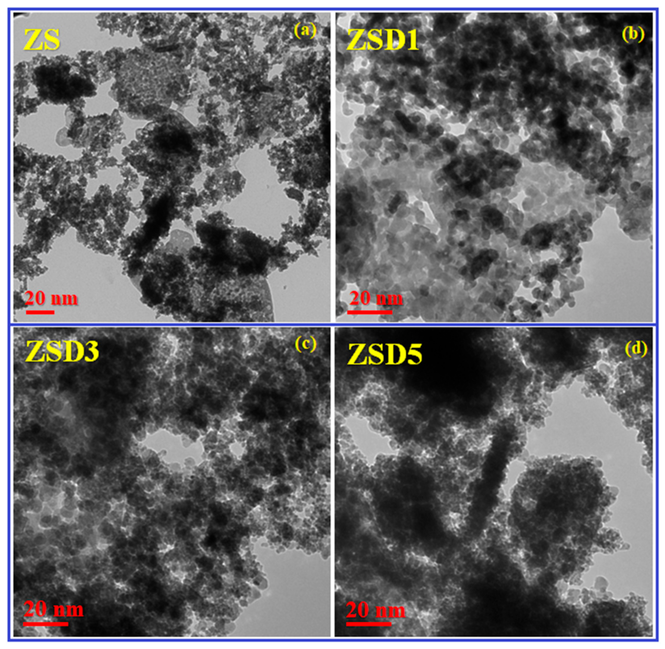
2.2. Morphological Study
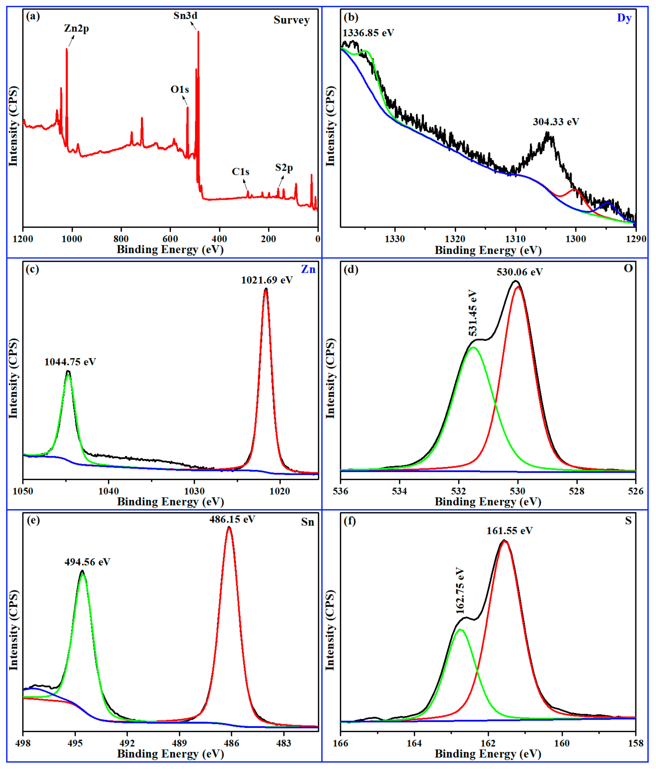
Our TEM study was able to determine the microstructure and surface structure of the as-prepared nanocomposites with a high level of precision. The TEM micrographs of the (a) ZS, (b) ZSD1, (c) ZSD3 and ZSD5 heterostructures are depicted in Figure 2. The micrographs clearly show that SnS has a sphere-like structure and that ZnO exhibits nanosheets. The TEM micrographs demonstrate an extremely noticeable contrast between the surfaces of ZnO and SnS. The ZnO/SnS nanocomposites have a wide interface, which is confirmed by the observed contrast for the surfaces [22]. Further, the structural distortion caused due to the inclusion of Dy species into Sn lattice was attributed to the alterations in the morphology of the ZSD heterostructures. Moreover, the nano-phase regime is confirmed as the grain size of the particles decreases with the integration of Dy ions into the ZS structure.
The TEM images show that the ZSD nanocomposites have an uneven shape as a result of the progressive addition (shown in ZSD1 to ZSD5) of a doping element, but they also have a surface that is noticeably rough and highly agglomerated. As shown in Figure 2a, the ZS nanocomposites’ morphology displays a highly contrasted nanorod (ZnO)- and spherical (SnS)-like structure. The incremental doping (1%, 3% and 5%) of Dy ions onto the ZS structure also causes the contrast to decrease, as seen in Figure 2b–d. The ZS nanostructure, however, is entirely covered by Dy ions, as seen in Figure 2d, giving the impression that it is covered in a thick layer of secondary ions with spherical shapes. It is caused by excessive Dy doping in the ZS lattice structure.
The HR-TEM image of the ZSD-3 sample is presented in Figure 3, and the ZnO nanosheets and SnS nanoparticles are indicated. The lattice spacing for the (1 0 0) plane of ZnO was measured at 0.28 nm. Similarly, the lattice spacing for the (1 2 0) plane of SnS was measured at 0.35 nm.

2.3. XPS Analysis

XPS is an effective tool to identify the constituent elements present in prepared samples and their surface analyses. The XPS spectra of the optimized Dy-doped ZnO/SnS (ZSD3) nanocomposites are presented in Figure 4. A survey scan (Figure 4a) is captured in a range of binding energies from 0 to 1350 eV to identify the constituent elements and their oxidation states in the as-synthesized nanocomposites. The survey scan spectra show a profusion of the Zn, Sn, O, S and Dy elements with a significant splitting of the binding energy peaks. In addition to these elements, a carbon (C) element peak is also noted at around 298 eV which is attributed to the environmental effect and control groups. The XPS spectrum of Dy3+ is presented in Figure 4b, and the XPS peaks at 1304.33 eV and 1336.85 eV are attributed to the Dy 3d5/2 and 3d3/2 states, respectively. Additionally, the splitting of these states confirms the occurrence of Dy3+ species with the spin-orbital splitting of 32.52 eV [23]. As depicted in Figure 4c, the spectrum of Zn is resolved into two obvious peaks around the energy values of 1021.69 and 1044.75 eV, corresponding to the Zn 2p3/2 and Zn 2p1/2 states, respectively. These peaks also authorize the occurrence of the Zn+2 oxidation state with a spin-orbital separation of 23.07 eV [24].
The XPS spectrum for oxygen (Figure 4d) has two significant bands at 530.06 eV and 531.45 eV, which are attributed to O1s with the oxidation state O2− in the optimized sample. The oxidation state of oxygen (O2−) shows the involvement of O in the Zn-O bond, and the spin-orbital splitting is found to be 1.39 eV [25]. Figure 4e illustrates the XPS spectrum of tin (Sn) in the optimized sample, which has two notable peaks at 486.15 eV and 494.56 eV, associated with the 3d5/2 and 3d3/2 states, respectively. The two sharp peaks show the presence of the Sn+2 oxidation state in the optimized sample with a separation in binding energy values of 8.41 eV [26]. As presented in Figure 4f, the sulphur spectrum consists of a significant band at around 161.55 eV and a shoulder band at 162.75 eV. The position of these peaks is ascribed to the S 2p3/2 and S 2p1/2 states, and it confirms the existence of the S2− oxidation state in the optimized ZSD-3 heterostructure with a spin-orbital splitting of 1.2 eV [27]. These findings strongly confirmed the oxidation state (Dy3+) and presence of dopant ions in the tin (Sn) lattice planes.

2.4. Optical Absorption Analysis

The optical bandgap energy and band alignment of different heterostructures can be determined via an absorption analysis. The optical absorption spectra and the corresponding Tauc plots of the ZS and ZSD heterostructures are depicted in Figure 5. As presented in Figure 5a, the absorption edge of the as-synthesized nanocomposites shifts towards a longer wavelength with increasing Dy content in the ZS host lattice. The red-shift shows the intrusion of Dy ions into the Sn lattice sites and the conceivable optimization of the sample [28]. The optical bandgap of the ZS and ZSD heterostructures was calculated by using the Tauc plots as presented in Figure 5b. The optical bandgap of the undoped (ZS) and Dy-doped composites (ZSD1, ZSD3 and ZSD5) is found to be 3.17, 3.05, 2.77 and 2.90 eV, respectively.
From Figure 5b, it can be inferred with certainty that when the concentration of the Dy doping in the ZS host nanocomposite rises, oxygen-related defects and vacancies cause a considerable fall in the optical energy bandgap values. Among all the composites, ZSD3 was found to have less of an energy bandgap owing to having a lower imperfection density at the interface of the heterostructure and a large separation of photoinduced e-h+ pairs. Further, a reduced recombination of the e-h+ pairs in the ZSD3 heterostructure’s interface would be favorable to maximize the photocatalytic activity. Hence, the ZSD3 sample displays a robust photocatalytic activity which indicates its optimized nature.

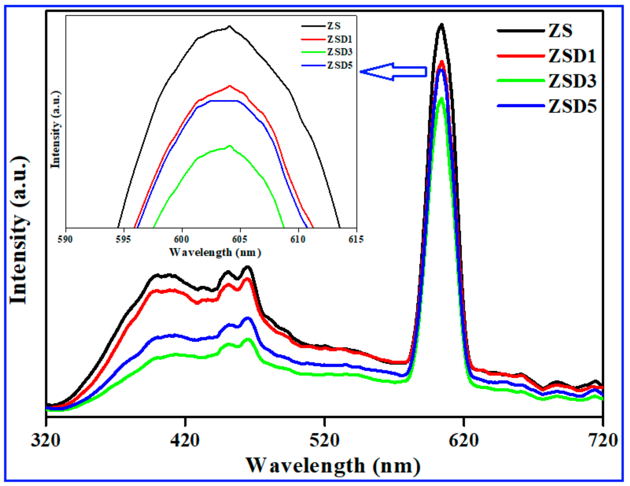
2.5. Photoluminescence Study

The PL study is employed to evaluate the photocatalyst’s ability to transmit energy and the reduced recombination of e-h+ pairs. The PL characteristic emission peaks are influenced by a material’s physical characteristics, such as dislocations, strain, vacancies and native point defects. Through the variation in PL intensity, the fundamental facts regarding the recombination of e-h+ pairs are studied. It is also recognized that an increase in the rate of e-h+ pair recombination will result in an increase in PL intensity [29]. The room temperature PL emission spectra of the ZS and ZSD heterostructures are depicted in Figure 6.
It is evident from the PL spectra that when the Dy dopant concentration increases, the luminous intensity of the emission bands decreases. The interaction between the Dy ions and their closest nearby host sites causes the luminescence intensity of the bands to diminish. Further, a decrease in PL intensity would lead to conditions for the possible separation of the photogenerated e-h+ pairs on the ZSD-3 heterostructure surface. However, on the other hand, the separation of e-h+ pairs could achieve a greater photocatalytic performance. Hence, low-PL-intensity composites are concluded to have a robust photocatalytic activity [30]. From the figure, it is noted that ZSD3 has the lowest PL intensity and a lower optical bandgap (2.77 eV) than the other nanocomposites. Therefore, it is established that the ZSD3 sample is a fascinating and well-designed nanocomposite material with an improved photocatalytic performance under light irradiation.

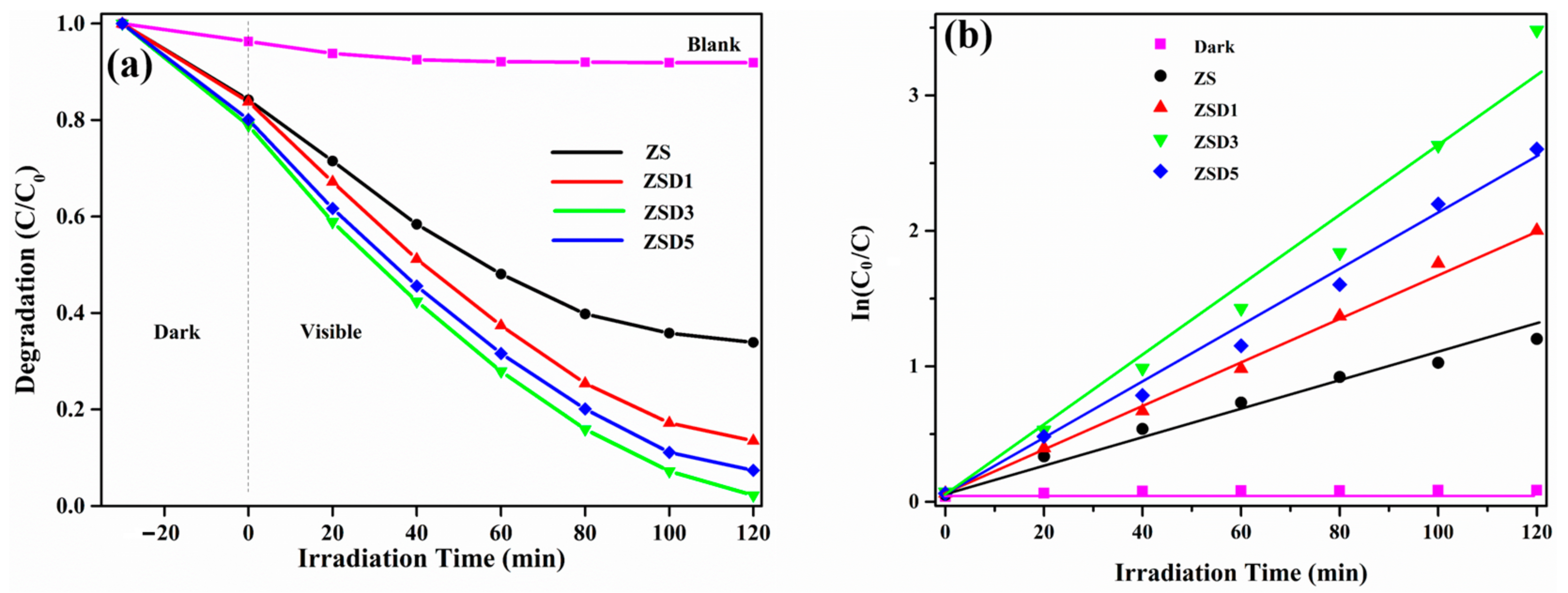
2.6. Photocatalytic Activity Studies

To save people and aquatic environments from health problems, the detoxification of organic contaminants, such as methylene blue (MB), from industrial effluent water is now required. To attain robust photocatalytic behavior under visible light, we set out to degrade the MB dye from wastewater. Figure 7 illustrates the photocatalytic activity of the ZS and ZSD heterostructures by depicting the efficiency of MB dye decolorization under solar light illumination. As depicted in Figure 7, the PCA of the prepared nanocomposites is assessed in an aqueous solution that is visibly sensitized at room temperature. Throughout the course of 120 min, an absorption spectrophotometer was used to periodically monitor the MB dye’s degradation concentration. To regulate the durability and effectiveness of the MB dye under solar light illumination, a degradation process and a blank experiment were first carried out using a pure MB dye aqueous solution. However, the aqueous solution had not yet achieved the maximum level of dye degradation. To get around this obstacle, nanophotocatalyst material, i.e., doping composites, were added to the aqueous solution while it was at room temperature and visible light was present. The sample was agitated with a magnetic stirrer in the dark to ensure that the photocatalyst material was impacted by the dye decolorization process, which resulted in the symmetry of the soaked adsorption [19].
It was found that the ZSD heterostructures (ZSD1, ZSD3 and ZSD5) outperformed the ZS nanocomposite in terms of PCA. The increase in photodegradation efficiency is ascribed to Dy ion-induced alterations in the bandgap energy of the pristine ZS heterostructures, which support the strong photocatalytic activity of the ZSD nanocomposites under visible light by hosting new energy bands within the optical bandgap range. Figure 7a displays the effect of Dy doping on the photocatalytic performance of ZS host nanocomposites. The dye degradation performance of the nanocomposites is represented as ZS < ZSD1 < ZSD5 < ZSD3. As depicted in Figure 7b, using the Langmuir–Hinshelwood kinetic expression [31], the graph showing ln(C0/Ct) vs. the irradiation time (t) has a straight line, signifying that the photocatalytic activity follows pseudo first-order kinetics behavior.
Figure 8a illustrates the proportion of the photocatalyst samples that degraded after 120 min of exposure to the MB dye solution against visible light. For the ZS, ZSD1, ZSD3 and ZSD5 photocatalysts, the proportions of the decolorization performance of the MB dye are 68.2, 88.5, 97.8 and 93.4%, respectively. The ZSD3 (optimized) photocatalyst, which is the most effective photocatalyst nanocomposite, can destroy almost 97.8% of the MB dye in 120 min, due to the plasmonic effect, i.e., the interaction of light with photocatalyst sample and large surface area. The kinetic rate constant (k) values for the doped and undoped samples under solar light are designated in Figure 8b. The derived rate constant values of the prepared samples are evaluated by using the following expression [32]:
Rate   constant   ( k ) = log   C 0 / C t   min 1
The projected kinetic rate constants are specified as 0.011, 0.0168, 0.0266 and 0.0214 min−1 for the synthesized heterostructures of ZS, ZSD1, ZSD3, and ZSD5. In addition, it is also noted that the optimized sample, i.e., ZSD3, has a high kinetic rate constant value, which in turn indicates that it is more effective than the other synthesized nanocomposites. Further, the utmost photodegradation of the MB dye in the case of the ZSD3 sample is due to the formation of a novel heterojunction and the lowest recombination of e-h+ pairs at the interface. The data regarding the optical bandgap, rate constant and degradation efficiency of the prepared samples are depicted in Table 2.
The results of the reusability test for the optimized sample are displayed in Figure 9. The reusability/recyclability of nanocomposites can be used in many real-world applications. In the present investigation, a reusability experiment was performed to understand the cyclic stability of the ZSD3 heterostructure [33]. The reusability test results showed that the photodegradation efficiency of the MB dye in the optimized sample gradually decreased from the first cycle to the fourth cycle and finally plateaued at around 94%. These results strongly show that the ZSD3 sample could be useful in various practical applications. Based on the above results, ZSD heterostructures exhibit a fabulous photodegradation performance when illuminated with visible light. It is also estimated that the synthesized photocatalyst could be utilized to remove organic toxins from wastewater. Hence, the current study could be useful for maintaining the cycle of aquatic ecosystems and supplying safe drinking water. Comparative data pertaining to the photodegradation performance of ZnO-based nanocomposites are presented in Table 3 [22,34,35,36,37,38,39,40,41,42].
When visible light is present, the photogenerated electrons and holes diffuse in opposite directions on the composite’s surface. After illumination with solar light, the exited electrons form CB of ZnO were injected into VB of SnS due to their proximity. The electrons in CB of SnS and holes in the VB of ZnO remained and participated in the photocatalytic redox reaction. Furthermore, the established nanocomposite heterojunction significantly reduces the rate of recombination for photogenerated e-h+ pairs, facilitating maximum charge separation on the nanocomposite surface [33]. The superior photocatalytic activity of the optimized nanocomposite (ZSD3) is further promoted by the pronounced separation of charge carriers on its surface. The Z-scheme photocatalytic mechanism explained above was further supported by scavenger tests. The scavenger’s effect of TEOA, BQ and IPA were investigated for scavenging holes (h+), superoxide radicals (·O2−) and hydroxyl radicals (·OH), respectively (Figure 10). Out of all the scavengers, BQ reduced most MB dye, which means the participation of superoxide radical was prominent in the photocatalytic reduction of MB dye. Hydroxyl radical also had a significant impact, but holes had a significantly lower impact when compared to that of superoxide and hydroxyl radicals.

2.7. Proposed Charge Carrier Transport Mechanism

The photocatalytic degradation mechanism is primarily determined by two factors: the optical bandgap of the optimized photocatalyst and the nanocomposite surface’s capacity to separate charge carriers. Figure 11 depicts the predicted transport mechanism of the charge carriers during photodegradation in the presence of the ZSD3 heterostructures under solar light. The diagram reveals that some of the Sn2+ sites in the ZnO/SnS nanocomposite are occupied by the doped Dy3+ ions, which allows the Dy ions to fully regulate the optical bandgap of the optimized nanocomposite. The introduction of Dy3+ ions alters the location of the Fermi level in both ZnO and SnS. Specifically, the valence band (VB) of SnS is positioned above the VB of the ZnO state, while the conduction band (CB) of SnS is now located just above the CB of the ZnO state [43]. Consequently, a different heterostructure of ZnO/Dy SnS may emerge at the heterostructure interface. This interface serves as a beneficial medium for facilitating the conversion of photoinduced e-h+ pairs to permissible sites, which improves the ZSD3 heterostructure.

3. Experimental Section

Synthesis of Dy3+ Doped ZnO/SnS Heterostructures

The experimental procedure is illustrated in Figure 12. First, 0.2 mol of Zn(CH3COO)2·2H2O was prepared in 50 mL of an ethanol/water solution. Next, a solution of 0.2 mol NaOH was separately prepared in another 50 mL ethanol/water matrix. After that, NaOH solution was gradually mixed dropwise with constant stirring into the above solution to form zinc oxide solution. Second, 50 mL of SnCl4·2H2O solution was prepared in 50 mL of ethanol/water mixture. This solution was then added to the ZnO solution. After 15 min of constant stirring, 50 mL of Na2S solution was added to the above mixture. Notably, the white precipitate changed to a light-yellow tint, indicating the fabrication of ZnO/SnS nanocomposite. Later, calculated amount of Dy (III) solution was added to the mixture and constantly agitated for 4 h. After filling a Teflon-lined autoclave with the mixture, it was placed in a hot oven at 220 °C for 12 h. Regular cleaning of the colloidal dispersion using ethanol and deionized water was performed to remove contaminants. Subsequently, the solution underwent centrifugation at a speed of 6000 rpm for almost 10 min. The residue material was then mechanically crushed into a fine powder after being dried for two hours at 100 °C in a hot-air oven (see more details in supplementary materials file). This process yielded dissimilar concentrations (1%, 3% and 5%) of ZSD heterostructures, achieved by incorporating variable mole percentages of Dy into the ideal ZnO/SnS samples. Throughout the entirety of this manuscript, the pristine ZnO/SnS is referred as ZS, while the doped heterostructures are labelled ZSD1, ZSD3 and ZSD5, respectively.

4. Conclusions

The following are the main conclusions drawn from this study on hydrothermally grown Dy3+ doped ZS heterostructures for improved photocatalysis:
Our XRD analysis results show the mixed-phase occurrence of hexagonal (ZnO) and orthorhombic (SnS) crystal structures with no more traces relevant to the Dy dopant.
The TEM micrographs depict the shape of ZnO as a sheet-like structure, whereas SnS appears to have a sphere-like structure with a more agglomerated trend in the presence of the Dy dopant.
The XPS study revealed that the Dy ions exhibited +3 oxidation state, i.e., Dy3+ in the optimized sample along with other elements, such as Zn2+, Sn2+, O2− and S2−.
The UV-DRS analysis described the redshift (longer wavelength), i.e., the optical bandgap decreases when the dopant content increases.
The PL study shows that intensity of the emission peaks diminishes with the increasing Dy content, and a lower-intensity sample will have a better photocatalytic performance.
The maximum photocatalytic degradation of the MB dye for the optimized sample (ZSD3) was found to be around 98% in 120 min.
The robust photocatalytic activity was observed for ZSD3 due to the maximal separation of photogenerated e-h+ pairs, the high surface area and the formation of novel heterojunction.

Supplementary Materials

The following supporting information can be downloaded at: https://www.mdpi.com/article/10.3390/catal13091292/s1, Supplementary Materials file.

Author Contributions

T.T.S.: Conceptualization, Methodology, Writing—original draft, Writing—review and editing. G.D.: Visualization, Investigation, Writing—review and editing. T.R.G.: Visualization, Investigation, Writing—review and editing. B.B.: Conceptualization, Formal analysis, Data curation, Writing—original draft, Writing—review and editing. K.Y.: Formal analysis, Data curation, Supervision, Resources, Writing—review and editing. All authors have read and agreed to the published version of the manuscript.

Funding

This research received no external funding.

Data Availability Statement

The data supporting the findings of this study can be found within the article.

Acknowledgments

This work was supported by the Materials & Parts Technology Development Program (20019447, Development of PI(Polyimide) separator manufacturing technology and equipment for 300 °C high heat-resistance lithium secondary battery) funded By the Ministry of Trade, Industry & Energy (MOTIE, Korea).

Conflicts of Interest

The authors declare no conflict of interest.

References

  1. Zhou, J.; Zhang, Z.; Kong, X.; He, F.; Zhao, R.; Wu, R.; Wei, T.; Wang, L.; Feng, J. A novel P-N heterojunction with staggered energy level based on ZnFe2O4 decorating SnS2 nanosheet for efficient photocatalytic degradation. Appl. Surf. Sci. 2020, 510, 145442. [Google Scholar] [CrossRef]
  2. Wang, H.; Yu, J.; Zhan, X.; Chen, L.; Sun, Y.; Shi, H. Direct 2D/2D Z-scheme SnNb2O6/ZnO hybrid photocatalyst with enhanced interfacial charge separation and high efficiency for pollutants degradation. Appl. Surf. Sci. 2020, 528, 146938. [Google Scholar] [CrossRef]
  3. AMakama, B.; Salmiaton, A.; Choong, T.S.Y.; Hamid, M.R.A.; Abdullah, N.; Saion, E. Influence of parameters and radical scavengers on the visible-light-induced degradation of ciprofloxacin in ZnO/SnS2 nanocomposite suspension: Identification of transformation products. Chemosphere 2020, 253, 126689. [Google Scholar] [CrossRef] [PubMed]
  4. Jia, T.; Fu, F.; Li, J.; Deng, Z.; Long, F.; Yu, D.; Cui, Q.; Wang, W. Rational construction of direct Z-scheme SnS/g-C3N4 hybrid photocatalyst for significant enhancement of visible-light photocatalytic activity. Appl. Surf. Sci. 2020, 499, 143941. [Google Scholar] [CrossRef]
  5. Sun, Y.J.; Yang, H.Y.; Zhao, Z.T.; Suematsu, K.; Li, P.W.; Yu, Z.C.; Zhang, W.D.; Hu, J. Fabrication of ZnO quantum dots@SnO2 hollow nanospheres hybrid hierarchical structures for effectively detecting formaldehyde. Sens. Actuators B 2020, 318, 128222. [Google Scholar] [CrossRef]
  6. Makama, A.B.; Salmiaton, A.; Saion, E.B.; Choong, T.S.Y.; Abdullah, N. Microwave-Assisted Synthesis of Porous ZnO/SnS2 Heterojunction and Its Enhanced Photoactivity for Water Purification. J. Nanomater. 2015, 2015, 108297. [Google Scholar] [CrossRef]
  7. Sajid, M.M.; Shad, N.A.; Javed, Y.; Khan, S.B.; Zhang, Z.; Amin, N.; Zhai, H. Preparation and characterization of Vanadium pentoxide (V2O5) for photocatalytic degradation of monoazo and diazo dyes. Surf. Interfaces 2020, 19, 100502. [Google Scholar] [CrossRef]
  8. Qamar, M.A.; Shahid, S.; Javed, M.; Sher, M.; Iqbal, S.; Bahadur, A.; Li, D. Fabricated novel g-C3N4/Mn doped ZnO nanocomposite as highly active photocatalyst for the disinfection of pathogens and degradation of the organic pollutants from wastewater under sunlight radiations. Colloids Surf. A 2021, 611, 125863. [Google Scholar] [CrossRef]
  9. Kannan, S.; Subiramaniyam, N.P.; Sathishkumar, M. Effect of annealing temperature and Mn doping on the structural and optical properties of ZnS thin films for enhanced photocatalytic degradation under visible light irradiation. Inorg. Chem. Commun. 2020, 119, 108068. [Google Scholar] [CrossRef]
  10. Saldaña-Ramírez, A.; Cruz, M.R.A.; Juárez-Ramírez, I.; Torres-Martínez, L.M. Influence of the power density and working pressure in the magnetron co-sputtering deposition of ZnO–SnO2 thin films and their effect in photocatalytic hydrogen production. Opt. Mater. 2020, 110, 110501. [Google Scholar] [CrossRef]
  11. Derikvandi, H.; Nezamzadeh-Ejhieh, A. An effective wastewater treatment based on sunlight photodegradation by SnS2–ZnS/clinoptilolite composite. Solid State Sci. 2020, 101, 106127. [Google Scholar] [CrossRef]
  12. Ouyang, B.; Zhang, K.; Yang, Y. Photocurrent Polarity Controlled by Light Wavelength in Self-Powered ZnO Nanowires/SnS Photodetector System. iScience 2018, 1, 16–23. [Google Scholar] [CrossRef] [PubMed]
  13. Manikandan, D.; Yadav, A.K.; Jha, S.N.; Bhattacharyya, D.; Boukhvalov, D.W.; Murugan, R. XANES, EXAFS, EPR, and First-Principles Modeling on Electronic Structure and Ferromagnetism in Mn Doped SnO2 Quantum Dots. J. Phys. Chem. C 2019, 123, 3067–3075. [Google Scholar] [CrossRef]
  14. Juntrapirom, S.; Tantraviwat, D.; Suntalelat, S.; Thongsook, O.; Phanichphant, S.; Inceesungvorn, B. Visible light photocatalytic performance and mechanism of highly efficient SnS/BiOI heterojunction. J. Colloid Interface Sci. 2017, 504, 711–720. [Google Scholar] [CrossRef] [PubMed]
  15. Kalpana, K.; Selvaraj, V. Development of ZnS/SnS/A-FA nanorods at ambient temperature: Binary catalyst for the removal of congo red dye and pathogenic bacteria from wastewater. J. Ind. Eng. Chem. 2016, 41, 105–113. [Google Scholar] [CrossRef]
  16. Jayswal, S.; Moirangthem, R.S. Construction of a solar spectrum active SnS/ZnO p–n heterojunction as a highly efficient photocatalyst: The effect of the sensitization process on its performance. New J. Chem. 2018, 42, 13689–13701. [Google Scholar] [CrossRef]
  17. Hegde, S.S.; Surendra, B.S.; Talapatadur, V.; Murahari, P.; Ramesh, K. Visible light photocatalytic properties of cubic and orthorhombic SnS nanoparticles. Chem. Phys. Lett. 2020, 754, 137665. [Google Scholar] [CrossRef]
  18. Muruganandam, S.; Murugadoss, G. Large-scale preparation of ZnS-ZnO-SnS nanocomposites: Investigation on structural and optical properties. Optik 2020, 220, 165187. [Google Scholar] [CrossRef]
  19. Khanchandani, S.; Kundu, S.; Patra, A.; Ganguli, A.K. Shell Thickness Dependent Photocatalytic Properties of ZnO/CdS Core–Shell Nanorods. J. Phys. Chem. C 2012, 116, 23653–23662. [Google Scholar] [CrossRef]
  20. Thirumala Rao, G.; Babu, B.; Stella, R.J.; Manjari, V.P.; Ravikumar, R.V.S.S.N. Spectral investigations on undoped and Cu2+ doped ZnO–CdS composite nanopowders. Spectrochim. Acta Part A 2015, 139, 86–93. [Google Scholar] [CrossRef]
  21. Joyce Stella, R.; Thirumala Rao, G.; Manjari, V.P.; Babu, B.; Krishna, C.R.; Ravikumar, R.V.S.S.N. Structural and optical properties of CdO/ZnS core/shell nanocomposites. J. Alloys Compd. 2015, 628, 39–45. [Google Scholar] [CrossRef]
  22. Masjedi-Arani, M.; Salavati-Niasari, M. Metal (Mn, Co, Ni and Cu) doped ZnO-Zn2SnO4-SnO2 nanocomposites: Green sol-gel synthesis, characterization and photocatalytic activity. J. Mol. Liq. 2017, 248, 197–204. [Google Scholar] [CrossRef]
  23. In, S.J.; Park, M.; Jung, J.W. Reduced interface energy loss in non-fullerene organic solar cells using room temperature-synthesized SnO2 quantum dots. J. Mater. Sci. Technol. 2020, 52, 12–19. [Google Scholar] [CrossRef]
  24. Elsheikh, A.H.; Yu, J.; Sathyamurthy, R.; Tawfik, M.M.; Shanmugan, S.; Essa, F.A. Improving the tribological properties of AISI M50 steel using SnS/ZnO solid lubricants. J. Alloys Compd. 2020, 821, 153494. [Google Scholar] [CrossRef]
  25. Chauhan, P.S.; Mishra, A.; Bhatt, G.; Bhattacharya, S. Enhanced He gas detection by V2O5-noble metal (Au, Ag, and Pd) nanocomposite with temperature dependent n- to p-type transition. Mater. Sci. Semicond. Process. 2021, 123, 105528. [Google Scholar] [CrossRef]
  26. Liu, Q.; Liu, S.; Wu, A.; Huang, H.; Zhou, L. SnS2 and SnS/SnS2 heterojunction nanosheets prepared by in-situ one-step sulfurization and visible light-assisted electrochemical water splitting properties. J. Alloys Compd. 2020, 834, 155174. [Google Scholar] [CrossRef]
  27. Zhang, Q.X.; Ma, S.Y.; Zhang, R.; Tie, Y.; Pei, S.T. Optimization ethanol detection performance manifested by SnS/SnS2 nanoparticles. Mater. Lett. 2020, 258, 126783. [Google Scholar] [CrossRef]
  28. Tang, R.; Su, H.; Sun, Y.; Zhang, X.; Li, L.; Liu, C.; Zeng, S.; Sun, D. Enhanced photocatalytic performance in Bi2WO6/SnS heterostructures: Facile synthesis, influencing factors and mechanism of the photocatalytic process. J. Colloid Interface Sci. 2016, 466, 388–399. [Google Scholar] [CrossRef] [PubMed]
  29. Joyce Stella, R.; Thirumala Rao, G.; Babu, B.; Manjari, V.P.; Reddy, C.V.; Shim, J.; Ravikumar, R.V.S.S.N. A facile synthesis and spectral characterization of Cu2+ doped CdO/ZnS nanocomposite. J. Magn. Magn. Mater. 2015, 384, 6–12. [Google Scholar] [CrossRef]
  30. Wang, L.; Zhai, H.; Jin, G.; Li, X.; Dong, C.; Zhang, H.; Yang, B.; Xie, H.; Sun, H. 3D porous ZnO–SnS p–n heterojunction for visible light driven photocatalysis. Phys. Chem. Chem. Phys. 2017, 19, 16576–16585. [Google Scholar] [CrossRef] [PubMed]
  31. Gupta, J.; Bahadur, D. Visible Light Sensitive Mesoporous Cu-Substituted ZnO Nanoassembly for Enhanced Photocatalysis, Bacterial Inhibition, and Noninvasive Tumor Regression. ACS Sustain. Chem. Eng. 2017, 5, 8702–8709. [Google Scholar] [CrossRef]
  32. Jana, T.K.; Pal, A.; Chatterjee, K. Self assembled flower like CdS–ZnO nanocomposite and its photo catalytic activity. J. Alloys Compd. 2014, 583, 510–515. [Google Scholar] [CrossRef]
  33. Babu, B.; Harish, V.V.N.; Shim, J.; Reddy, C.V. Solution combustion synthesis of SnO2–NiO p–n heterojunction nanocomposite for photocatalytic application. J. Mater. Sci.—Mater. Electron. 2018, 29, 16988–16996. [Google Scholar] [CrossRef]
  34. Dharmana, G.; Masabattula, P.S.R.; Potukuchi, D.M. Enhanced photocatalytic activity in hydro-thermally grown nano structured ZnO/SnS core–shell composites. Z. Naturforsch. A 2022, 77, 153–169. [Google Scholar] [CrossRef]
  35. Khaki, M.R.D.; Shafeeyan, M.S.; Raman, A.A.A.; Daud, W.M.A.W. Evaluating the efficiency of nano-sized Cu doped TiO2/ZnO photocatalyst under visible light irradiation. J. Mol. Liq. 2018, 258, 354–365. [Google Scholar] [CrossRef]
  36. Shanmugam, V.; Jeyaperumal, K.S. Investigations of visible light driven Sn and Cu doped ZnO hybrid nanoparticles for photocatalytic performance and antibacterial activity. Appl. Surf. Sci. 2018, 449, 617–630. [Google Scholar] [CrossRef]
  37. Dharmana, G.; Srinivasa Rao, M.P.; Potukuchi, D.M. Visible light driven robust photocatalytic activity in vanadium-doped ZnO/SnS core-shell nanocomposites for decolorization of MB dye towards wastewater treatment. Inorg. Nano-Metal Chem. 2022, 52, 1059–1076. [Google Scholar] [CrossRef]
  38. Karthik, K.V.; Raghu, A.V.; Reddy, K.R.; Ravishankar, R.; Sangeeta, M.; Shetti, N.P.; Reddy, C.V. Green synthesis of Cu-doped ZnO nanoparticles and its application for the photocatalytic degradation of hazardous organic pollutants. Chemosphere 2022, 287, 132081. [Google Scholar] [CrossRef]
  39. Rao, G.T.; Ravikumar, R.V.S.S.N. Novel Fe-doped ZnO-CdS nanocomposite with enhanced visible light-driven photocatalytic performance. Mater. Res. Innov. 2021, 25, 215–220. [Google Scholar] [CrossRef]
  40. Dharmana, G.; Gurugubelli, T.R.; Masabattula, P.S.R.; Babu, B.; Yoo, K. Facile Synthesis, Characterization, and Photocatalytic Activity of Hydrothermally Grown Cu2+-Doped ZnO/SnS Nanocomposites for MB Dye Degradation. Catalysts 2022, 12, 328. [Google Scholar] [CrossRef]
  41. Dharmana, G.; Gurugubelli, T.R.; Viswanadham, B.; Bathula, B.; Yoo, K. Novel In-Situ Fabrication of Fe-Doped Zinc Oxide/Tin Sulfide Heterostructures for Visible-Light-Driven Photocatalytic Degradation of Methylene Blue. J. Chem. 2023, 2023, 1407395. [Google Scholar] [CrossRef]
  42. Pant, B.; Pant, H.R.; Barakat, N.A.M.; Park, M.; Jeon, K.; Choi, Y.; Kim, H.-Y. Carbon nanofibers decorated with binary semiconductor (TiO2/ZnO) nanocomposites for the effective removal of organic pollutants and the enhancement of antibacterial activities. Ceram. Int. 2013, 39, 7029–7035. [Google Scholar] [CrossRef]
  43. Liu, Z.; Ma, Z. Promoting the photocatalytic activity of Bi4Ti3O12 microspheres by incorporating iron. RSC Adv. 2020, 10, 19232–19239. [Google Scholar] [CrossRef] [PubMed]
Figure 1. XRD pattern of undoped and Dy3+ doped ZnO/SnS nanocomposites.
Catalysts 13 01292 g001
Figure 2. TEM micrographs of undoped and Dy3+ doped ZnO/SnS nanocomposites.
Catalysts 13 01292 g002
Figure 3. HR-TEM image of undoped and Dy3+ doped ZnO/SnS nanocomposites.
Catalysts 13 01292 g003
Figure 4. XPS spectra of optimized Dy3+ doped ZnO/SnS nanocomposites (ZSD3).
Catalysts 13 01292 g004
Figure 5. (a) Optical absorption; (b) Tauc plots of undoped and Dy-doped ZnO/SnS nanocomposites.
Catalysts 13 01292 g005
Figure 6. PL spectra of undoped and Dy-doped ZnO/SnS nanocomposites.
Catalysts 13 01292 g006
Figure 7. Photocatalytic study of undoped and Dy3+ doped ZnO/SnS nanocomposites: (a) Evaluation of photocatalytic efficiency of photocatalyst under visible light irradiation; (b) kinetics of MB dye vs. irradiation time.
Catalysts 13 01292 g007
Figure 8. (a) The degradation efficiency of MB dye, and (b) the kinetic rate constant of undoped and Dy3+ doped ZnO/SnS nanocomposites.
Catalysts 13 01292 g008
Figure 9. Reusability test results of 3% Dy3+ doped ZnO/SnS nanocomposites (ZSD3).
Catalysts 13 01292 g009
Figure 10. Radical trapping experiment for the degradation of MB dye over 3% Dy3+ doped ZnO/SnS nanocomposites (ZSD3).
Catalysts 13 01292 g010
Figure 11. Charge carrier transport mechanism in Dy3+ doped ZnO/SnS optimized nanocomposite under visible light irradiation.
Catalysts 13 01292 g011
Figure 12. Experimental procedure of Dy3+ doped ZnO/SnS nanocomposites.
Catalysts 13 01292 g012
Table 1. The statistics related to crystallite size, d-spacing, microstrain and dislocation density for undoped and Dy3+ doped ZnO/SnS nanocomposites.
SampleCrystallite Size D (nm)d-Spacing (Å)Micro Strain (ε) × 10−3Dislocation Density (δ) × 1015 lines/m2
ZS12.53.8538.2164.147
ZSD112.13.4218.6294.657
ZSD311.62.8498.9564.928
ZSD510.92.2789.4545.247
Table 2. The optical bandgap, rate constant and degradation efficiency of undoped and Dy3+ doped ZnO/SnS nanocomposites.
SampleBandgap (eV) Kinetic Rate Constant (min−1)Degradation Efficiency (%)
ZS3.170.01168.2
ZSD13.050.016888.5
ZSD32.770.026697.8
ZSD52.900.021493.4
Table 3. Comparison of MB dye degradation of ZnO/SnS-based nanocomposites.
Catalyst UsedSynthesis MethodDyeLight SourceIrradiation Time (min)Degradation Efficiency (%)Ref.
ZnO/SnS nanocompositeHydrothermalMBVisible lamp21095.2[34]
Cu doped TiO2/ZnO compositeSol-gel methodMBVisible light12073.2[35]
Co doped ZnO-Zn2SnO4-SnO2Simple sol-gel methodeosin YUV light irradiation15087[22]
Sn:Cu:ZnO nanocompositesMicrowave-assisted ultra-sonicated precipitation processMBVisible light18098.5[36]
V doped ZnO/SnS compositeHydrothermal methodMB300 W Visible light12096.4[37]
Cu doped ZnO nanocompositesGreen methodMBUV-light7591.3[38]
Fe doped ZnO-CdS compositeSimple chemical synthesisMB150 W visible light8071[39]
Cu doped ZnO/SnS nanocompositeHydrothermalMBSolar12097.2[40]
Fe doped ZnO/SnS nanocompositesHydrothermalMBVisible light12095.8[41]
Carbon decorated TiO2/ZnO compositeElectro-spinning methodMBUV light (365 nm)12068[42]
Dy-doped ZnO/SnS nanocompositesHydrothermalMBVisible light12097.8Present Work
Disclaimer/Publisher’s Note: The statements, opinions and data contained in all publications are solely those of the individual author(s) and contributor(s) and not of MDPI and/or the editor(s). MDPI and/or the editor(s) disclaim responsibility for any injury to people or property resulting from any ideas, methods, instructions or products referred to in the content.

