Article

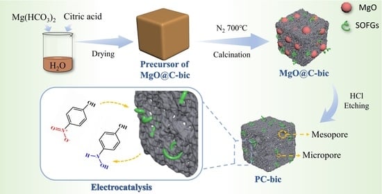
Templating Synthesis of Hierarchically Porous Carbon with Magnesium Salts for Electrocatalytic Reduction of 4-Nitrophenol

Hubei Key Laboratory of Biomass Fibers and Eco-Dyeing & Finishing, College of Chemistry and Chemical Engineering, Wuhan Textile University, Wuhan 430200, China
*
Authors to whom correspondence should be addressed.
Catalysts 2023, 13(7), 1132; https://doi.org/10.3390/catal13071132
Submission received: 16 June 2023 / Revised: 13 July 2023 / Accepted: 17 July 2023 / Published: 20 July 2023
(This article belongs to the Special Issue Graphene Related Materials for Catalytic Applications)

Abstract

:
Hierarchically porous carbon (PC) was synthesized by a templating method, using magnesium salts (Mg(HCO3)2, MgC2O4 and MgO) as template precursors and citric acid as carbon precursor. During the carbonization process, besides the production of MgO particles, many gases (e.g., CO2/NO2/H2O) were also released and acted as a porogen to generate pores in carbon. The resulting composite (MgO@C) was subsequently treated with HCl solution to remove the MgO templates, yielding hierarchically porous carbon. The surface oxygen functional groups over porous carbon were characterized by TPD and XPS, which showed that the PC-bic, synthesized using Mg(HCO3)2 as the template precursor, had the highest value among the PCs. As expected, the PC-bic exhibited the best performances for electrocatalytic reduction of 4-nitrophenol, with a peak current of −135.5 μA at −0.679 V. The effects of 4-nitrophenol concentration, buffer solution pH and scanning rate on the electrocatalytic activities, as well as the stability of PC-bic for the reaction were investigated.

Graphical Abstract

1. Introduction

Porous carbon (PC) is a class of carbon materials with certain pore structures, whose properties are mainly determined by the pore size, pore amounts and pore distribution [1,2,3,4]. Because of its high surface area, strong resistance to acid and base, controllable pore size and structure, facile surface modification and excellent electrical conductivity, the PCs have great applications in various fields, including lithium-ion batteries [5,6,7,8,9], supercapacitors [10,11,12,13], catalysis [14,15,16,17,18,19,20] and gas adsorption [21,22,23], and has become a focus of attention in recent years. Meanwhile, the abundant carbon sources (carbon precursors) used to prepare PC, such as biomass [24,25], polymers [26], metal-organic frameworks [13] and carbon-containing organic salts [27], and the various methods to prepare PC, enable the PC, exhibiting multitudinous structures and properties. The preparation of PC and the correlation of its structural properties with application performances is, therefore, an attractive topic and deserves deep research.
Templating is an effective method to prepare PC in that it only requires a carbonization process, which simplifies the synthesis steps and avoids the loss of carbon yield, while obtaining controllable and uniform pore size [28,29]. Traditionally, this method challenges the problems of synthesizing a shaped template (e.g., SBA-15 [30,31,32]), which is a time-consuming process. In addition, the removal of such templates requires a strong acid or base, which would influence the surface chemistry of carbon materials. For these reasons, the use of metal salts, e.g., carbonates [33,34], as templates to synthesize PC receives attention and is an attractive strategy, by which not only the removal of metal oxides (decomposed from the metal salts) generates pores, but the gases (e.g., CO2 [35]) released from the metal salts also open pores in the structure, improving the porosity and enriching the pore structures. Moreover, the metal oxides are strong basic oxides, which can be facilely removed with acid, shortening the etching time and weakening the influence on the surface chemistry.
Zhao et al. used CaCO3 as a template to synthesize PC, finding that although the insolubility of CaCO3 makes it difficult to uniformly mix with carbon precursors, the release of CO2 significantly improves the porosity of the obtained carbon [36]. Yuan et al. synthesized PC by co-pyrolysis of waste polyester textiles with magnesium-containing compounds, which yields porous carbon with a high surface area, various surface functional groups and a disordered layer structure [37]. Our group recently reported a new templating method to synthesize PC by etching the in situ formed perovskites (LaFeO3) [38]. In addition to the pores generated by the removal of perovskite templates and the release of gases, the moving of metal oxides to form perovskite creates extra pores in the structure. All these results suggest that the use of metal salts as templates can effectively improve the porosity of PC by the removal of the resulting metal oxides and the release of gases.
Among the metal oxide templates, MgO receives much interest for the following advantages [39,40]: (1) MgO has good thermal and chemical stability, hence the structure and composition of MgO will not change and it will not react with carbide during the carbonization process; (2) MgO is recyclable and can be easily removed by dilute acids; (3) the pore structure and pore size of PC can be regulated by selecting different Mg contained precursors. In this work, we attempt to prepare hierarchically PC by a templating method, using Mg(HCO3)2, MgC2O4 and C6H6MgO7 as precursors. The obtained PCs contain both microporous and mesoporous pores, which are generated from the release of gases and the etching of MgO templates that decomposed from the magnesium salts, respectively. Among them, PC from Mg(HCO3)2 exhibit a high surface area up to 942.3 m2/g. The surface chemistry and textural properties of PCs are characterized by XRD, TGA, N2 physisorption, TEM, TPD-MS and XPS measurements.
Catalytic performances of the obtained PCs are evaluated by the electroreduction of 4-nitrophenol (4-NP), which is a toxic chemical that causes serious harm to the human body and the aqueous environment, and it is in the “Priority Pollutants List” of the U.S. Environmental Protection Agency. Electrocatalytic reduction is an effective method to remove toxic nitroaromatics [41] for its simple and rapid process, and the reduction product, aromatic amines, is 500 times less toxic than the nitroaromatic analogues [42]. Saraswathi et al. synthesized nanostructured Cu(II)-curcumin complex by a simple in situ electrochemical procedure [43]. The electroreduction peak current over the Cu-curcumin/GCE was 2.8 times higher and the overpotential was reduced by 310 mV compared to bare glassy carbon electrode (GCE). The electroreduction performance of metal oxides is relatively lower, but the activity can be enhanced by compounding other agents, such as reduced graphene oxide (rGO) [44,45]. As well as the low resistance surface, rGO exhibited much higher electrocatalytic reduction properties than graphene oxides [46]. After NiFe2O4 nanoparticles were homogeneously anchored onto rGO nanosheets, the resulting nanocomposites displayed a considerably high catalytic current response towards the irreversible reduction of 4-NP. In our previous work, metal nitrates, as template precursors, were decomposed along with the emission of oxidative gases, which greatly promoted the generation of oxygen-containing functional groups over the obtained porous carbon with excellent activity for 4-NP reduction [38]. In this work, different magnesium salts were used as template precursors to investigate the surface number of oxygen-containing functional groups over porous carbon and the electrocatalytic performance for 4-NP reduction. The effects of reaction conditions and the stability of the PCs in the reaction are thoroughly studied and discussed.

2. Results and Discussion
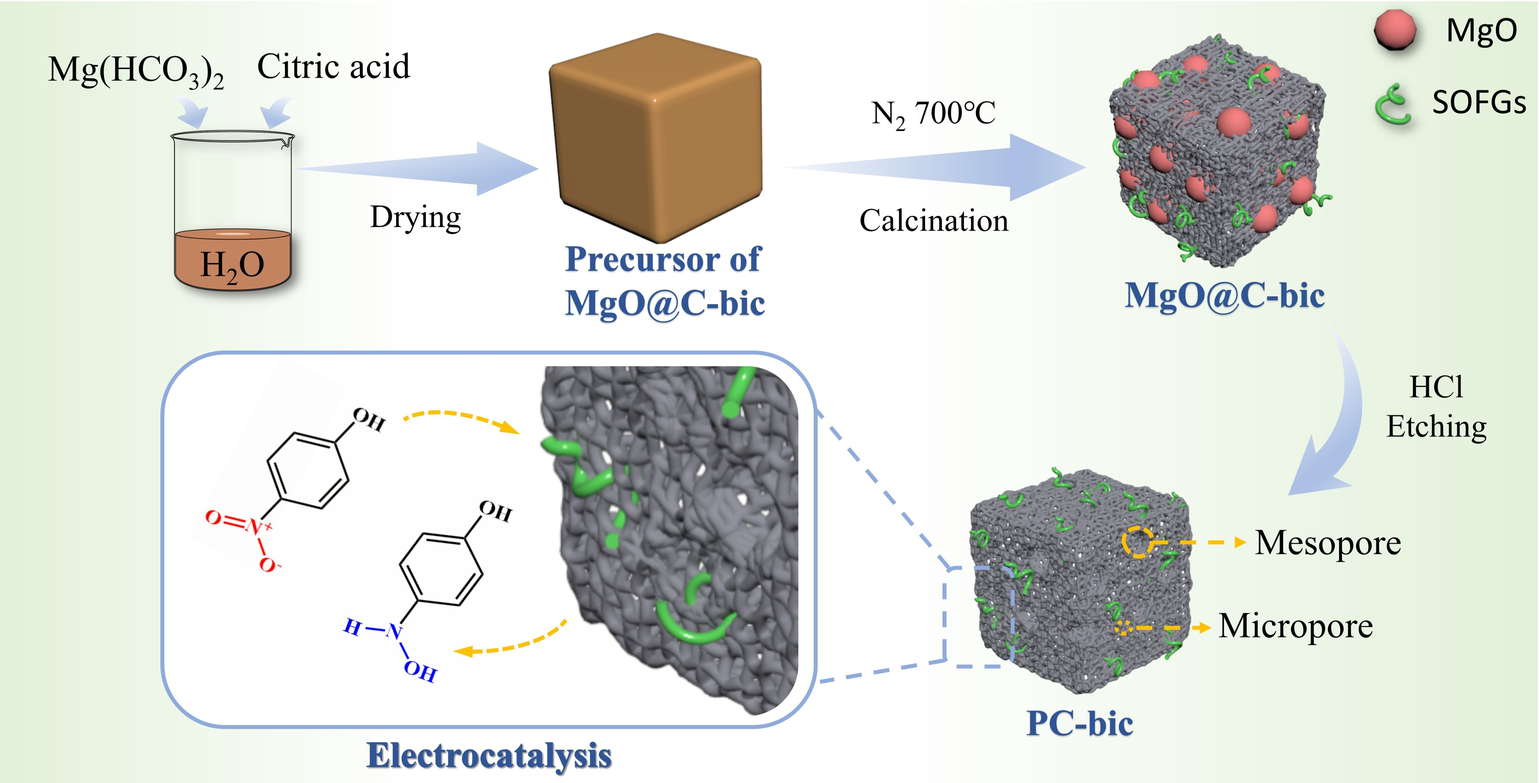
2.1. XRD Patterns

Figure 1A shows the XRD patterns of the MgO@C-n (n = bic, oxa and oxi) composites, showing that after 4 h of carbonization at 700 °C in N2 flow, all the magnesium salts are decomposed to MgO. The diffraction peaks at 37°, 43°, 62°, 75° and 79° correspond to the (111), (200), (220), (311) and (222) planes of MgO, respectively. The crystallite sizes of MgO@C-bic, MgO@C-oxa and MgO@C-oxi, calculated with the Scherrer equation, are 8.8 nm, 10.9 nm and 8.5 nm, respectively. MgO@C-oxa shows a slightly larger crystallite size than MgO@C-bic, which could be because the MgC2O4 is directly decomposed into MgO (one-step process), while the decomposition of Mg(HCO3)2 undergoes a two-step process (e.g., Mg(HCO3)2 = MgCO3 + H2O, MgCO3 = MgO + CO2), as observed in the TGA profiles below. Hence, the MgO particles decomposed from MgC2O4 are more facile to aggregate during the carbonization process. No diffraction peaks attributable to carbon are observed in the XRD patterns due to its amorphous phase and low content of carbon, as suggested elsewhere [47].
The XRD patterns of the PCs are present in Figure 1B, showing two broad diffraction peaks at 23.5° and 43° that are assigned to the (002) and (100) planes of graphite carbon respectively [48]. No other diffraction peaks are detected in the XRD patterns, indicating that the templates have been completely removed from the PCs, after the treatment with HCl solution.

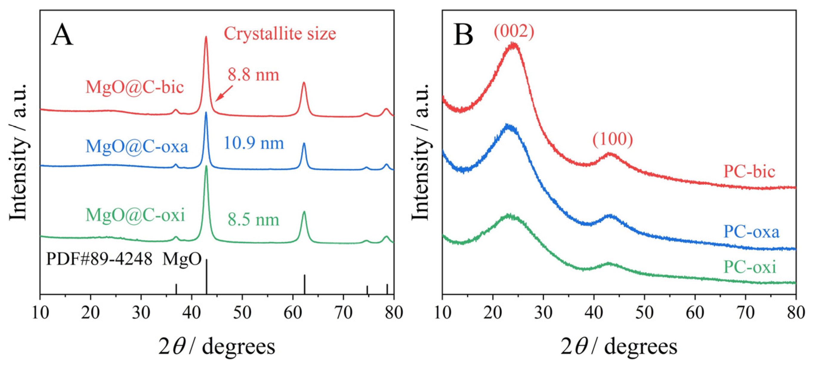
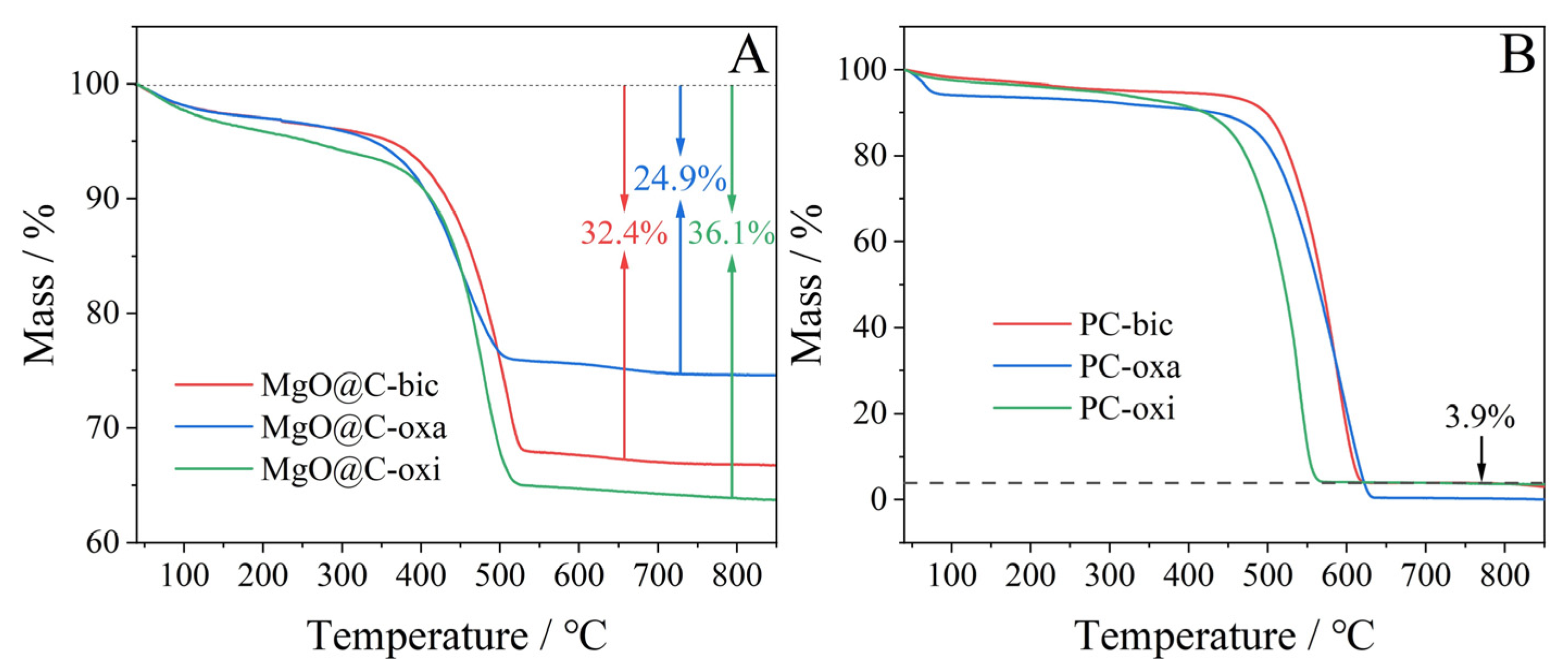
2.2. TGA-DSC Profiles
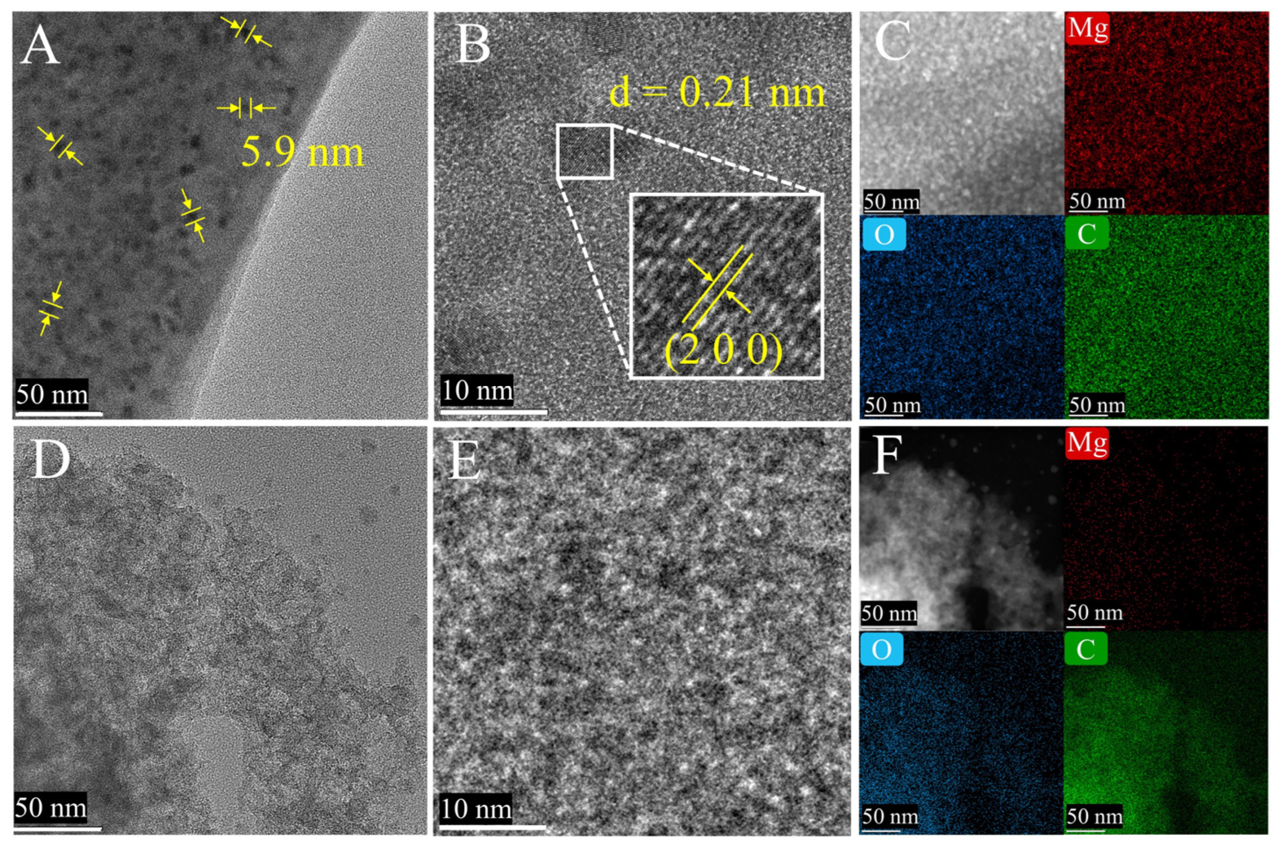
To simulate the carbonization process, N2 atmosphere is applied to perform the TGA-DSC profiles of the precursors. For the citric acid, see Figure 2A, three weight loss stages appear and can be classified as below: the first stage at 80–130 °C is due to the dehydration of crystal water of the citric acid, the second stage at 130–170 °C is due to the intramolecular dehydration between the citric acid, and the third stage after 170 °C is due to the carbonization of citric acid.
The TGA profiles of the magnesium precursors are also plotted (Figure S1). Mg(HCO3)2 undergoes an extra weight loss stage in the range of 200~300 °C when compared to MgC2O4. This confirms that the decomposition of Mg(HCO3)2 is a two-step process, and that of MgC2O4 is a one-step process. Nevertheless, both can be finally decomposed to MgO at a temperature above 550 °C, which is lower than the carbonization temperature (700 °C).
For the citric acid and MgO mixture, the first dehydration stage of citric acid is not clearly observed, see Figure 2B, which could be because the weight loss is too small to be detected (due to the presence of MgO) and most of the water may be absorbed by MgO, forming Mg(OH)2. This phenomenon also happens to citric acid mixed with Mg(HCO3)2 and MgC2O4 (Figure 2B,C). For similar reasons, although the second dehydration stage appears (due to the continuous release of water), the temperature is postponed to 160 °C. According to the DTG curves, this interval consists of two steps: the decomposition of citric acid, and the loss of magnesium salt crystal water or the partial decomposition of anions (e.g., OH). As the temperature increases, the weight loss of the magnesium precursors, as well as the carbonization of citric acid, appear. As expected, the weight loss of the “Mg(HCO3)2 + citric acid” mixture is in a wide range, compared to that of the “MgC2O4 + citric acid” mixture, since the decomposition of Mg(HCO3)2 is a two-step process and that of MgC2O4 is a one-step process.
Apart from the weight loss caused by dehydration, three new stages appear at temperatures above 220 °C for the mixture “MgO + citric acid”, which could be due to the formation of magnesium citrate (MgO + 2HCA = Mg(CA)2 + H2O, HCA: citric acid), the partial decomposition of Mg(CA)2, and the carbonization of citric acid, respectively (Figure 2D).
Figure 3A shows the TGA profiles of the MgO@C composites conducted in an air atmosphere, which aims to evaluate the carbon content of the MgO@C-n composites. It is seen that the type of precursors greatly affects the carbon content, in the sequence of MgO@C-oxi (36.1%) > MgO@C-bic (32.4%) > MgO@C-oxa (24.9%). The low carbon content of MgO@C-oxa could be due to the drastic decomposition of MgC2O4 during the carbonization process, thus more heat is released at a certain time, causing more citric acid to be oxidized and gasified. This also implies that the composite contains more MgO particles, and the yielded carbon would have more pores and higher surface area after etching the MgO particles, as confirmed by N2 physisorption isotherms below. The small residue of the carbon material (<4 wt.%) confirms that the MgO particles are mostly removed after the etching treatment, see Figure 3B.

2.3. TEM Images

TEM images of MgO@C-bic and PC-bic show that the carbon has a relatively transparent texture, implying the presence of large amounts of micropores in the structure, see Figure 4. For MgO@C-bic, the MgO particles are homogeneously dispersed in carbon, with a particle size of ca. 5.9 nm, see Figure 4A, which is quite similar to the pore size of PC-bic from the N2 physisorption (centered at 5.9 nm, see below). The lattice distance of 0.21 nm in Figure 4B can be indexed to the (200) plane of MgO [22], which confirms that MgO is the decomposition product of Mg(HCO3)2.
The STEM elemental mappings show that the Mg, O and C atoms are uniformly dispersed in MgO@C-bic, see Figure 4C, which suggests that the MgO particles are finely dispersed in carbon, as said above. The density of Mg atoms greatly reduces and is almost invisible, from MgO@C-bic to PC-bic (Figure 4F), indicating that the MgO particles have been removed, with a residual weight of less than 3.9 wt.%, see Figure 3B above. The O atoms are also clearly observed in the PC-bic, which suggests that oxygen-containing groups are generated and presented on the surface of PC-bic.

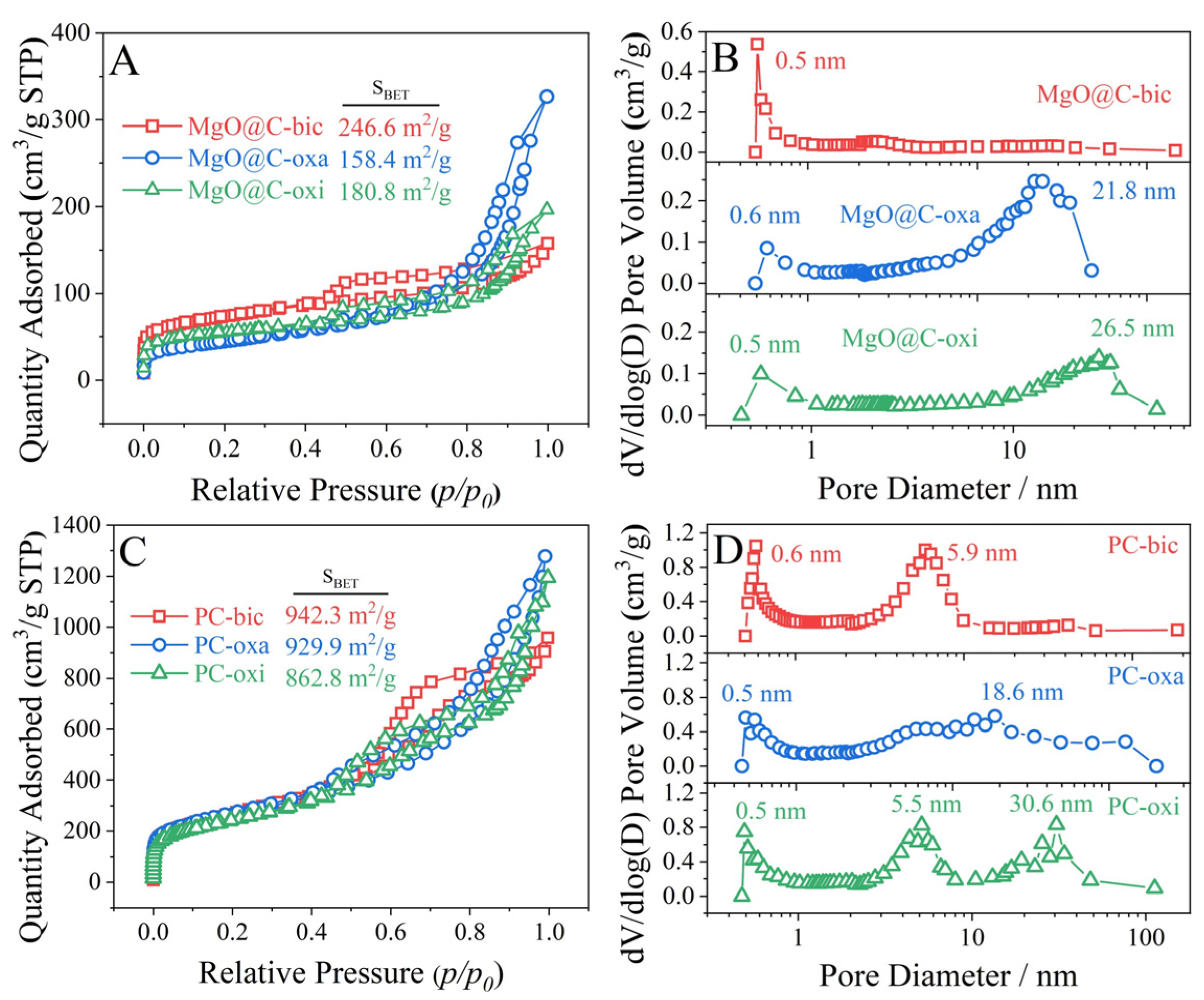
2.4. N2 Physisorption Isotherms
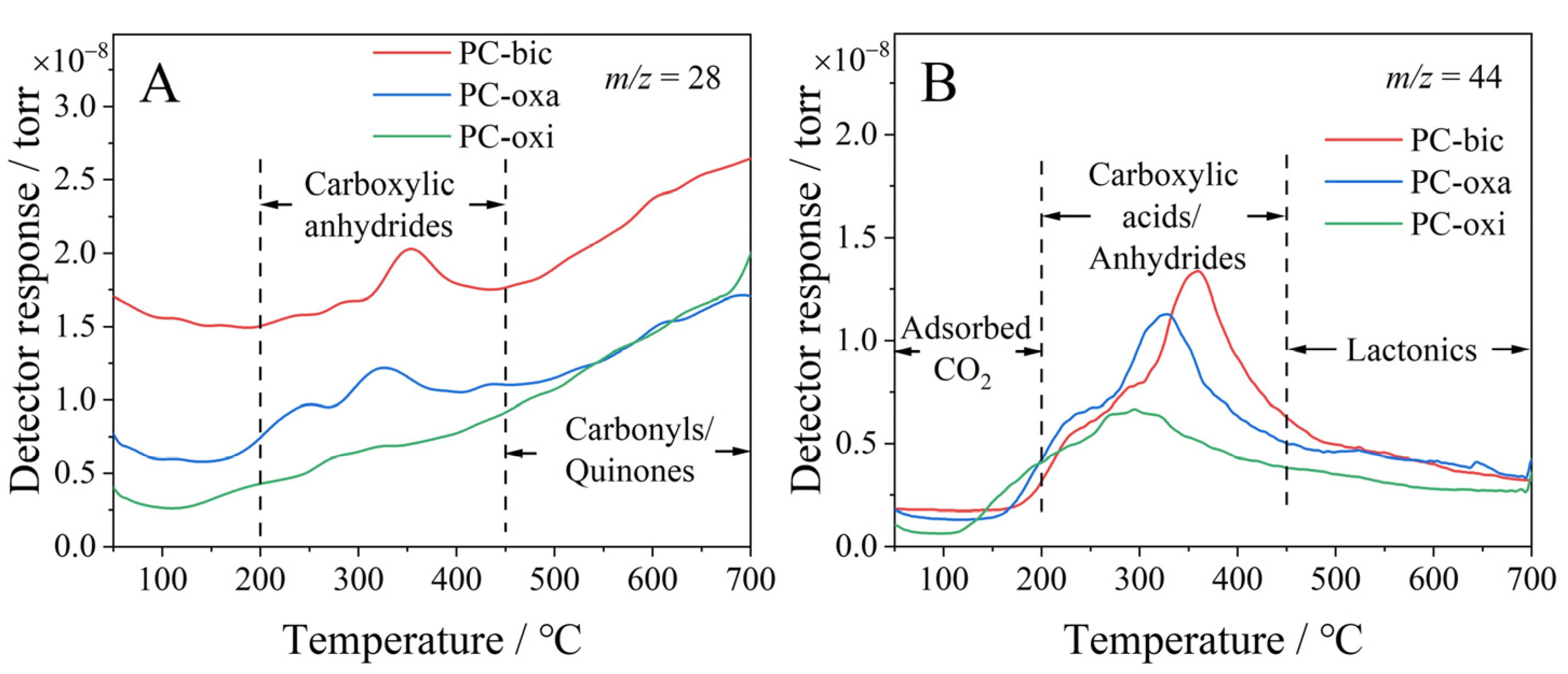
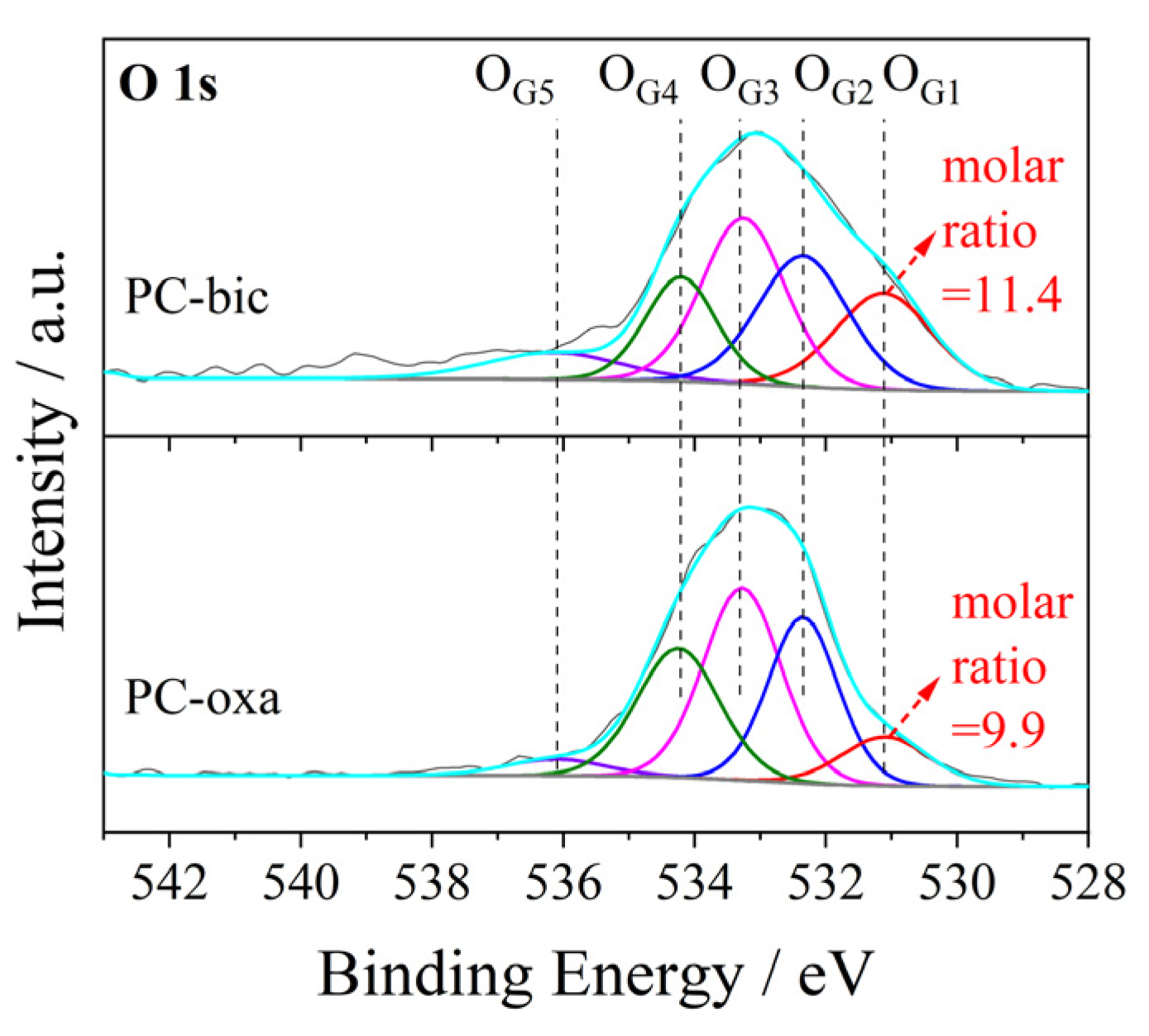
N2 physisorption isotherms are conducted to evaluate the textural properties of the MgO@C composites and the PCs. For the isotherms (Figure 5A,C), a sharp increase in N2 adsorption at p/p0 < 0.05 is observed for all materials, which implies the presence of micropores that originate from porous carbon. The variation in isothermal shape at p/p0 = 0.4~0.99 indicates that different pore structures are formed depending on the magnesium salts, which have varied decomposition behaviors. The large increase in N2 adsorption quantity, from the MgO@C to the PC, indicates that new pores are created and/or blocks in the pores are removed after being treated with HCl solution. This also implies that the MgO particles are etched from the composites, leaving pores in the PCs. By comparison, the MgO@C-oxa exhibits the lowest surface area, which could be due to its larger MgO particle size and, in particular, low carbon content, as seen from the XRD and TGA results.
For the pore distribution, see Figure 5B, only one type of pore, with a diameter less than 0.7 nm, is appreciably observed for MgO@C-bic, while two types of pores are observed for MgO@C-oxa and MgO@C-oxi, with an additional pore centered at ~21.8 nm and ~26.5 nm respectively. This is verified by N2 physisorption isotherms of MgO@C composites and suggests that the decomposition behavior of MgC2O4 and Mg(CA)2 is different from that of Mg(HCO3)2. After being treated by HCl solution, the resulting PC-bic and PC-oxi exhibit new pores at 5.9 and 5.5 nm, respectively, due to the etching of MgO particles. In contrast, the PC-oxa exhibits a wide pore size distribution and the number of pores at 21.8 nm are greatly decreased. This could be because the removal of large MgO particles within MgO@C-oxa causes the collapse of the pore walls.
Based on the above discussion, it is inferred that the micropores under a diameter of 0.7 nm are caused by the gases (e.g., CO2) released from the decomposition of citric acid and magnesium salts, and the large pores, with a diameter of ca. 5.5 nm, are generated due to the etching of MgO particles. These pores generated after the etching process suggest that the particle size of MgO is ca. 5.5 nm, which is coincident with the particle size observed in the TEM images (~5.9 nm), see Figure 4A.
The surface areas of the PCs changes in order: PC-bic > Pc-oxa > PC-oxi, which could be related to the properties of the MgO@C composites. The large surface area of PC-bic is because the Mg(HCO3)2 undergoes a two-step decomposition process, producing a large amount of MgO templates with smaller particle sizes. Once the MgO particles are etched, abundant pores are generated, leading to its high surface area (942.3 m2/g). In contrast, the decomposition of MgC2O4 is a one-step process, which would lead to larger MgO particles; hence, the PC-oxa exhibits a surface area (929.9 m2/g) after the MgO particles are etched. For PC-oxi, although MgO@C-oxi has small MgO particles (see Figure 1A), it has no additional anionic groups to combust (except the citric acid) and releases gases to generate extra pores in carbon, and hence, it exhibits a low surface area (805.9 m2/g).

2.5. TPD and XPS

The surface chemistries of the PCs were investigated by temperature-programmed desorption (TPD) measurements, which is a powerful method to classify the surface oxygen functional groups (SOFGs) of carbon materials by analyzing the release temperature of CO and CO2, as proposed by Figueiredo et al. [49,50]. To clearly differentiate the gases (i.e., CO, CO2 and H2O) decomposed from the SOFGs of carbon, the TPD instrument is connected with a mass spectrometer (MS) and substrates with m/z ratios of 44, 28 and 18, that correspond to CO2, CO and H2O, respectively, are monitored.
Figure 6A,B depicts the MS spectra monitored for CO and CO2 (which for H2O can be found in Figure S2). Generally, two desorption regions can be classified for CO-TPD, with the first at 200~450 °C assignable to CO decomposed from carboxylic anhydrides groups, and the second at above 450 °C to the decomposition of carbonyls or quinones [51]. By comparison, the PC-bic shows a larger desorption peak area and higher desorption temperature than the others, indicating that PC-bic has more surface carboxylic anhydrides groups.
For CO2 MS spectra, three desorption regions can be classified: the first at temperatures below 200 °C, which is due to the desorption of CO2 physically adsorbed on the surface, the second at 200~450 °C, which is due to the decomposition of carboxylic acids and/or anhydrides, and the third at temperatures above 450 °C, which is due to the decomposition of lactonics [49]. Similarly, the PC-bic shows a larger desorption peak area and a higher desorption temperature, partly attributed to its bigger surface area, which enables more SOFGs to be generated and exposed on the surface.
Hence, it is concluded that multiple SOFGs, including carboxylic acid, anhydrides, carbonyls, quinones and lactonics, are generated on the surface of the PCs, and the PC-bic possesses the greatest amount of SOFGs due to its large surface area and the mild exothermal process (a two-step decomposition process of Mg(HCO3)2).
To confirm and clarify the SOFGs generated on the PCs, we perform the O 1s XPS spectra for the materials and show the results in Figure 7. According to the literature [52,53], five peaks can be fitted for the spectra, with the first at 531.3 eV (OG1) attributed to the carbonyl oxygen atoms of ketone; the second at 532.3 eV (OG2) which relates to the carbonyl oxygen in esters and anhydrides, or the oxygen in hydroxyls or ethers; the third at 533.2 eV (OG3) which corresponds to the ether oxygen atoms in esters or anhydrides; the fourth at 534.4 eV (OG4) attributed to the carboxylic oxygen, and the last at 536.3–536.8 eV (OG5) which relates to the oxygen of the adsorbed water. This supports the above results and confirms that the SOFGs of ketones, esters, anhydrides and carboxylic acid are generated on the PCs. In addition, it was found that the molar ratio of OG1 for PC-bic (11.4) is higher than that for PC-oxa (9.9), which indicates a larger content of carbonyl groups from ketones and explains the significant discrepancy between PC-bic and PC-oxa observed at the 200~450 °C region of the TPD profiles.

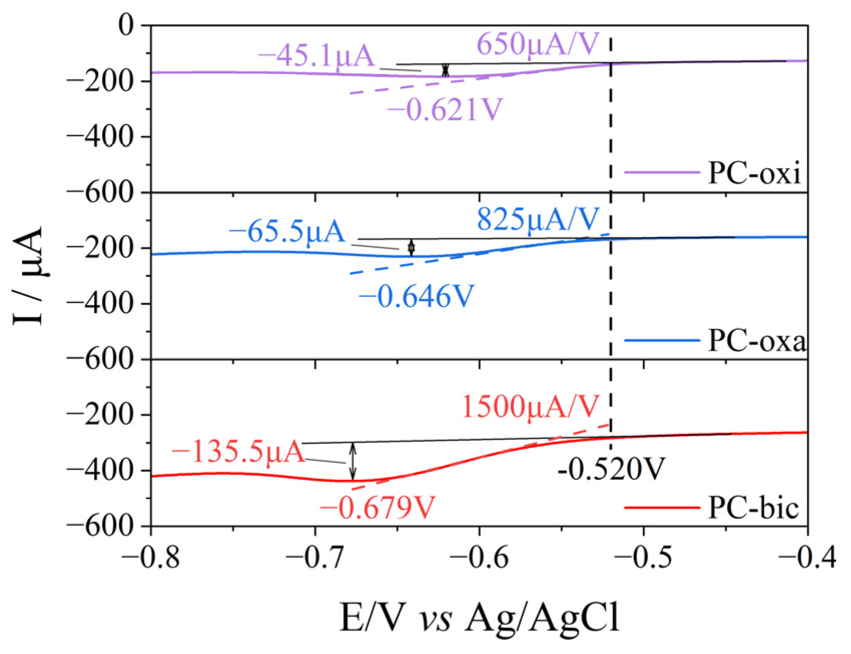
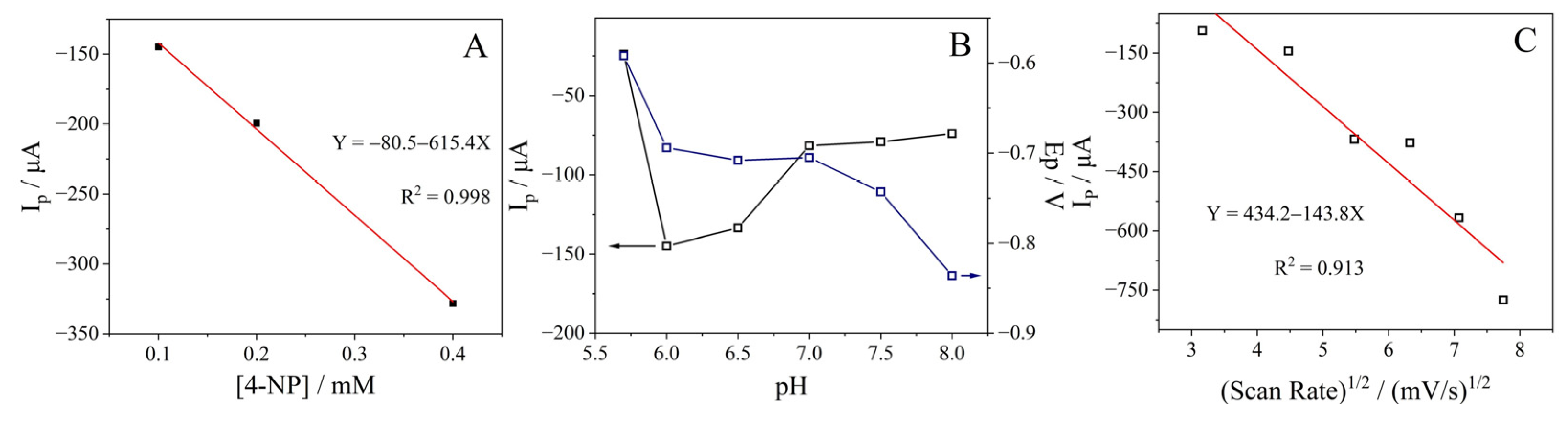
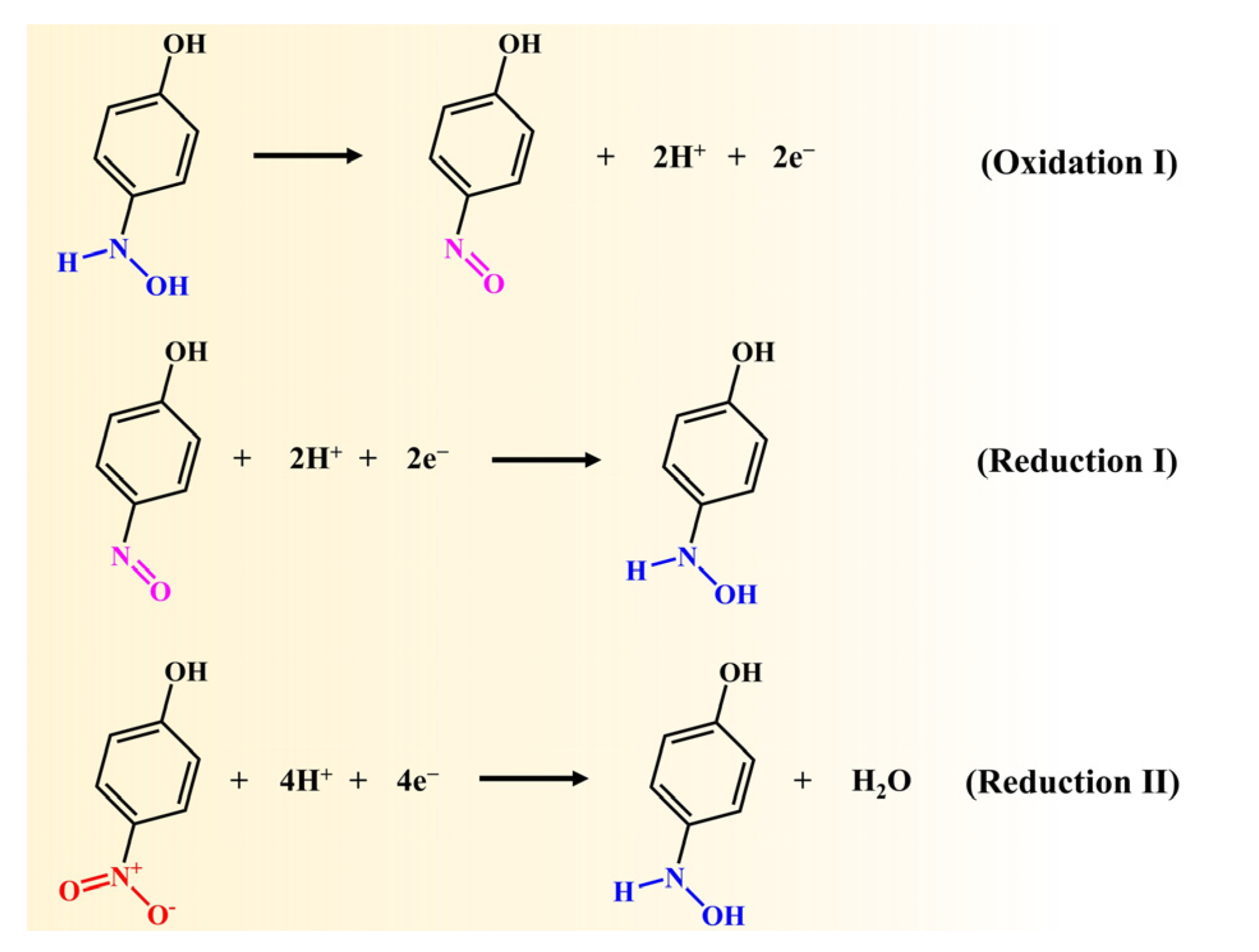
2.6. Electrocatalytic Reduction of 4-Nitrophenol

The electrocatalytic performances of the PCs for the reduction of 4-NP (0.1 mM) are conducted in 0.2 M phosphate buffer solution (pH = 6.0). Figure S3 shows that the CV curves of PC-direct is similar to that of the GC electrode, indicating that the PC-direct has negligible contribution to the reaction. The cyclic voltammetry (CV) current rapidly increases after coating the PCs on the GC electrode, and the PC-bic exhibits the strongest current, see Figure S4A. This is probably because the PC-bic has the highest surface area (942.3 m2 g−1). When the PC-modified GC electrodes were evaluated for the electrocatalytic reduction of 0.1 mM 4-NP in 0.2 M phosphate buffer solution (pH = 6.0), PC-bic also exhibited the strongest reduction peak current (Figure S4B). In contrast, the PC-oxi exhibited the weakest CV current due to its low surface area and few SOFGs. From the Tafel slopes for the electrocatalytic reduction over PCs (Figure S5), PC-bic had the lowest Tafel slope, which confirmed the best electrocatalytic performance. To investigate the electrochemically active surface area (ECSA), the PCs electrocatalysts were subjected to CV measurements in the non-faradaic region from −0.4 to 0.3 V with scan rates from 40 to 100 mV/s (Figure S6). The ECSA is usually used to calculate double-layer capacitance (Cdl) as a measurement standard. The Cdl value of PC-bic is 4.7 mF/cm2 which is much higher than PC-oxa at 2.3 mF/cm2, and PC-oxi at 1.7 mF/cm2, respectively. It indicates that PC-bic has the highest value of ECSA. The excellent electrocatalytic activity of PC-bic was attributed to the high ECSA and the largest amounts of SOFGs, which act as the active sites of the reaction. Furthermore, it is noted that two peaks appear in the reduction process and one appears in the oxidation process, which could be, respectively, attributed to the reduction of 4-NP to 4-hydrooxyminophenol, the reduction of 4-nitrosophenol and the oxidation of 4-hydrooxyminophenol, as depicted in Scheme 1 [43].
Table 1 lists the current, current density and potential of 4-NP reduction peaks obtained from the PCs. The peak current increases from −45.1 μA for PC-oxi to −65.5 μA for PC-oxa and further to −135.5 μA for PC-bic (the corresponding CV curves can be found in Figure S4B). Because of the large increase in the CV current, the potentials associated with the 4-NP reduction peak are slightly postponed, from −0.621 V to −0.646 V and to −0.679 V. Whereas the potential to initiate the reduction of 4-NP is similar for all the PCs, see Figure 8, indicating that they have similar electrocatalytic reduction ability. On the other hand, from the reduction peak slope, which reflects the rate of the reduction reaction, it was seen that the PC-bic had a slope of 1500 μA V−1, which is 2.3 times larger than that of PC-oxi. This demonstrates that the electroreduction of 4-NP is more facilitated over the PC-bic. Moreover, the electrocatalytic activity of PC-bic is compared with the other electrocatalysts reported in the literature (Table S1). The electrocatalytic activity of PC-bic is preferable to metal oxide, graphitic carbon nitride, graphene oxide or the composites of metal oxides and nanosheets [38,43,44,45,46,54]. By comparing the 4-NP reduction peak currents, it reveals that PC-bic has the higher peak current density than that of Cu-curcumin and PC-c, indicating the superior electrocatalytic reduction performance of PC-bic.
The effects of the reaction conditions on the electrocatalytic performances of PC-bic for 4-NP reduction are further investigated. Figure 9A shows that the peak current is linearly increased with the increase in 4-NP concentration (the corresponding CV curves can be found in Figure S7A), indicating that the PC-bic is efficient for the reaction even at a 4-NP concentration of 0.4 mM.
Figure 9B presents the variation of the peak current with the pH of the phosphate buffer solution (the corresponding CV curves can be found in Figure S7B). Because the protons in the electrolyte are involved in the 4-NP electroreduction process, the pH value has a significant effect on the reaction activity. The results show that the highest activity is obtained at pH = 6.0, with CV current of −135.5 μA and overpotential of −0.679 V. This pH value is thus selected throughout the reaction in this work.
The effect of the scanning rate on the reaction activity (or peak current) is also studied, showing that the current increases with the scanning rate, accompanied with a slight leftward shift of the peak potential, see Figure 9C (the corresponding CV curves can be found in Figure S7C). The linear relationship between the reduction peak current and the square root of the scanning rate illustrates that the electrocatalytic reduction of 4-NP is determined by the mass transfer rate over the working electrode.
Finally, the cycling performance of PC-bic for electroreduction of 4-NP is also conducted. After each CV test, the working electrode is flushed with distilled water three times and then immersed into a new phosphate buffer solution containing 4-NP for the next test. Five cycling experiments are performed, and the results are listed in Table 1, showing no appreciable changes in the reduction potential, although a slight variation in the current (and hence the slope) appears (the corresponding CV curves can be found in Figure S8). From TEM images of recycled PC-bic (Figure S9), abundant pores are distributed throughout the sample, similar to fresh PC-bic samples. This suggests that the PC-bic has good electrocatalytic stability for the reduction of 4-NP.

3. Experimental Section

3.1. Catalyst Preparation

A total of 4 mmol Mg(HCO3)2 and 8 mmol citric acid were dissolved in 10 mL deionized water and then heated in a water bath at 80 °C with stirring until a gel was formed. The gel was dried overnight at 100 °C and calcined in a N2 atmosphere at 700 °C for 4 h (heating rate of 3 °C/min), yielding a carbon coated MgO composite (named MgO@C-bic). To obtain porous carbon, the MgO@C-bic composite was added to a 50 mL HCl solution (6 mol/L) and stirred for 48 h to etch the MgO particles. The product was filtered, washed 3 times with distilled water and finally dried in a vacuum oven at 80 °C for 6 h to obtain the porous carbon, PC-bic.
For comparison, three other PCs were prepared: two were prepared using MgC2O4 and MgO as precursors (with the same procedures). The composites were named MgO@C-oxa and MgO@C-oxi, and the porous carbon was named PC-oxa and PC-oxi, respectively. The other one was prepared by directly heating the citric acid at 700 °C for 4 h under a N2 atmosphere and was named PC-direct.

3.2. Characterizations

X-ray diffraction (XRD) patterns were measured on an X-ray instrument (Ultima IV, Rigaku, Japan) using Kα radiation (λ = 1.5418 Å). The measurement was conducted within the range of 10 to 80°, while the scanning speed was 10°/min. N2 physisorption isotherms were obtained on a surface area and porosity analyzer (3H-2000PS2, BEISHIDE, Beijing, China) at −196 °C. The samples were vacuum degassed at 150 °C, for 5 h, before the measurements. The surface area was calculated using the Brunauer–Emmett–Teller (BET) method and the pore volume was obtained from the Barrett–Joyner–Halenda (BJH) method. Transmission electron microscopy (TEM) images were obtained by a scanning transmission electron microscope apparatus (FEI Talos F200x, Thermo Scientific, Waltham, MA, USA). Thermal gravimetric analysis (TGA) was carried out on a TGA/DSC 3+ thermal analyzer (Mettler Toledo, Zurich, Switzerland) from 40 to 850 °C, with a heating rate of 10 °C/min in a N2 or air atmosphere. For evaluating the carbon content, the experiment was conducted in a dynamic air atmosphere (50 mL/min); for simulating the synthesis process (used to determine the decomposition temperature of metal salts and citrates), the experiment was conducted in a N2 atmosphere (50 mL/min). X-ray photoelectron spectroscopy (XPS) measurements were recorded on a Thermo Scientific K-Alpha apparatus equipped with a monochromated Al Kα X-ray source. Binding energy was calibrated using the C 1s at a binding energy of 284.6 eV. Peak fitting was performed using the Thermo Scientific Advantage software (v5.948).
Temperature programmed desorption (TPD) experiments were carried out on a chemisorption analyzer (Huasi, Changsha, China) connected with a mass spectrometer (HPR-20 EGA, Hiden, Warrington, UK), as follows: 0.1 g samples were loaded in a quartz tube and passed with Helium (30 mL/min). The sample was pretreated at 150 °C for 1 h before the measurement. After the baseline reached stable, the temperature was raised from 50 °C to 700 °C to decompose the surface oxygen functional groups (SOFGs), with a heating rate of 10 °C/min. The components of the downstream gases were monitored online by the mass spectrometer, using m/z signals of 18 (H2O), 28 (CO) and 44 (CO2).

3.3. Electrochemical Reductions

Electrocatalytic reduction of 4-nitrophenol reaction was carried out on a CHI 636E electrochemical workstation (Chenhua, Shanghai, China) equipped with a three-electrode cell. Ag/AgCl was used as the reference electrode and platinum wire was used as the counter electrode. A glassy carbon (GC) electrode (5 mm diameter) polished with alumina slurry was sonicated in distilled water for 10 min prior to use. The working electrode was prepared by depositing the PCs onto the GC electrode as follows: 459 µL isopropanol and 41 µL 0.3 wt.% Nafion were mixed, 5.0 mg PCs was weighed and dispersed in this solution and sonicated for 30 min. Thereafter, 10 µL of the resulting ink was dropped onto the GC electrode. The mass of carbon deposited on the GC electrode was 0.1 mg. Cyclic voltametric curves were recorded from −0.9 to 0.4 V at a scanning rate of 20 mV s−1.
The reaction solution consisted of 0.2 mol L−1 phosphate buffer solution (pH = 6.0) and 0.1 mmol L−1 4-nitrophenol. The electrolyte was purged with N2 flow (30 mL/min) for 30 min to remove the dissolved oxygen before initiating the electrocatalytic reduction of 4-NP by a three-electrode cell. Stability tests were carried out as follows: after the reaction was completed, the working electrode was removed and rinsed 3 times with distilled water. Thereafter, the working electrode was placed in a new and fresh reaction solution for the next cyclic voltametric test.

4. Conclusions

Hierarchically porous carbon (PC) is synthesized by an in situ templating method using magnesium salts as templating precursors. The decomposition of magnesium salt produces not only MgO particles, which are used as a template to generate mesopores by etching with HCl solution, but also gases (e.g., CO2) that can generate micropores by bubbling from the interior of carbon precursors. Specifically, the use of magnesium salts with a mild decomposition process has the possibility to produce small MgO particles and reduce the carbon loss, yielding PC with a high surface area and more surface oxygen functional groups (SOFGs). As a result, the porous carbon, PC-bic, synthesized with Mg(HCO3)2 as a precursor shows a high surface area (942.3 m2 g−1) and more SOFGs than that prepared with MgC2O4 as a precursor, since the decomposition of Mg(HCO3)2 is a two-step process, while the decomposition of MgC2O4 is a one-step process. The SOFGs of PCs are analyzed with TPD and XPS measurements, showing that carboxylic acid, anhydrides, carbonyls, quinones and lactonics are generated on the surface. Catalytic performances of the PCs are evaluated by electrocatalytic reduction of 4-NP within a three-electrode cell, which shows that the PC-bic is more favorable for the reaction, due to its high surface area and large SOFGs, which are active sites of the reaction. The effects of the reaction conditions indicate that the PC-bic can work at a 4-NP concentration of 0.4 mM at a pH value of 6.0, and the reaction is determined by the mass transfer rate over the working electrode. Moreover, the PC-bic is stable in the reaction and no appreciable activity loss is observed within five cycles.

Supplementary Materials

The following supporting information can be downloaded at: https://www.mdpi.com/article/10.3390/catal13071132/s1, Figure S1: TGA profile of magnesium precursors conducted in N2 atmosphere.; Figure S2: MS signal of H2O obtained from the TPD of PC-n (n = bic, oxa and oxi); Figure S3: CV curves of the PC-direct and Glassy Carbon for electrocatalytic reduction of 4-nitrophenol (0.1 mM) in 0.2 M phosphate buffer solution at pH 6.0, with a scan rate of 20 mV s−1; Figure S4: CV curves of PCs and Glassy Carbon electrode in: (A) 0.2 M phosphate buffer solution at pH 6.0 and (B) 0.2 M phosphate buffer solution at pH 6.0 containing 4-nitrophenol (0.1 mM), with a scan rate of 20 mV s−1; Figure S5: The Tafel slopes of PC-bic, PC-oxi and PC-oxa samples; Figure S6: CV curves of: (A) PC-bic, (B) PC-oxa, (C) PC-oxi with different scan rates; (D) Cdl curves of PC-bic, PC-oxa and PC-oxi; Figure S7: (A) CV curves of PC-bic in 0.2 M phosphate buffer solution (pH = 6.0) at various concentrations of 4-nitrophenol; (B) Effect of pH on the CV curves of PC-bic in 0.2 M phosphate buffer solution (pH = 6.0) with 0.1 mM 4-nitrophenol; (C) CV curves of PC-bic for electrocatalytic reduction of 4-nitrophenol (0.1 mM) obtained at scan rates of 10–60 mV s−1 in a 0.2 M phosphate buffer solution (pH = 6.0); Figure S8: CV curves of PC-bic for electrocatalytic reduction of 4-nitrophenol (0.1 mM) within five cycles in 0.2 M phosphate buffer solution (pH = 6.0); Figure S9: TEM images of: (A) Fresh PC-bic and (B) recycled PC-bic after the electrocatalytic reduction of 4-NP; Table S1. The reaction conditions and activities of varied catalysts for electrocatalytic reduction of 4-NP.

Author Contributions

W.G.: methodology, investigation, writing—original draft preparation, and visualization; P.X.: investigation and visualization; J.Z.: conceptualization, methodology, resources, writing—review and editing, supervision, project administration, and funding acquisition. All authors have read and agreed to the published version of the manuscript.

Funding

This research was funded by the National Natural Science Foundation of China (42277485, 21976141, 22102123), the Department of Science and Technology of Hubei Province (2021CFA034), the Department of Education of Hubei Province (T2020011, Q20211712), and the Opening Project of Hubei Key Laboratory of Biomass Fibers and Eco-Dyeing & Finishing (STRZ202202, STRZ202101).

Data Availability Statement

Not applicable.

Conflicts of Interest

The authors declare no conflict of interest.

References

  1. Fang, X.; Li, W.; Chen, X.; Wu, Z.; Zhang, Z.; Zou, Y. Controlling the microstructure of biomass-derived porous carbon to assemble structural absorber for broadening bandwidth. Carbon 2022, 198, 70–79. [Google Scholar] [CrossRef]
  2. Yong, X.; Yin, Q.; Sha, P.; Zhang, Q.; Pang, B.; Yu, J.; Dong, H.; Yu, L.; Dong, L. Walnut shell-derived porous carbon with MgSO4 modification for high-performance capacitive deionization. Diam. Relat. Mater. 2023, 136, 110063. [Google Scholar] [CrossRef]
  3. Zhang, Y.; Wang, R.; Chen, W.; Song, K.; Tian, Y.; Li, J.; Shi, G. Microstructure and electrochemical properties of porous carbon derived from biomass. Int. J. Electrochem. Sci. 2023, 18, 100190. [Google Scholar] [CrossRef]
  4. Peng, L.; Peng, H.; Li, W.; Zhao, D. Monomicellar assembly to synthesize structured and functional mesoporous carbonaceous nanomaterials. Nat. Protoc. 2023, 18, 1155–1178. [Google Scholar] [CrossRef] [PubMed]
  5. Ma, G.; Yang, W.; Xu, C.; Che, S.; Li, Y.; Liu, H.; Chen, N.; Zhang, G.; Liu, H.; Wu, N.; et al. Nitrogen-Doped porous carbon embedded Sn/SnO nanoparticles as high-performance lithium-ion battery anode. Electrochim. Acta 2022, 428, 140898. [Google Scholar]
  6. Cheng, X.; Tang, C.; Yan, C.; Du, J.; Chen, A.; Liu, X.; Jewell, L.; Zhang, Q. Preparation of porous carbon spheres and their application as anode materials for lithium-ion batteries: A review. Mater. Today Nano 2023, 22, 100321. [Google Scholar] [CrossRef]
  7. Ou, J.; Deng, H.; Li, B.; Li, K.; Li, M. High content of nitrogen doped porous carbon prepared by one-step calcination for enviable rate lithium ion batteries. Diam. Relat. Mater. 2023, 133, 109696. [Google Scholar] [CrossRef]
  8. Koketsu, T.; Ma, J.; Morgan, B.J.; Body, M.; Legein, C.; Goddard, P.; Borkiewicz, O.J.; Strasser, P.; Dambournet, D. Exploiting cationic vacancies for increased energy densities in dual-ion batteries. Energy Storage Mater. 2020, 25, 154–163. [Google Scholar] [CrossRef]
  9. Deng, X.; Zhao, B.; Sha, Y.; Zhu, Y.; Xu, X.; Shao, Z. Three Strongly Coupled Allotropes in a Functionalized Porous All-Carbon Nanocomposite as a Superior Anode for Lithium-Ion Batteries. Chemelectrochem 2016, 3, 698–703. [Google Scholar] [CrossRef]
  10. Mo, F.; Wu, X. MgO template-assisted synthesis of hierarchical porous carbon with high content heteroatoms for supercapacitor. J. Energy Storage 2022, 54, 105287. [Google Scholar] [CrossRef]
  11. Wang, X.; Huang, Z.; Jin, H.; Wang, S.; Zhang, Q.; Xiao, H.; Hu, X.; Li, J.; Sheng, S. Cistanches herba residues derived nitrogen and oxygen self-doped porous carbon for high performance supercapacitor. J. Alloys Compd. 2023, 956, 170264. [Google Scholar] [CrossRef]
  12. Zhang, Y.; Yue, P.; Zhang, C.; Wang, Y.; Wu, X. Facile synthesis of three-dimensional interconnected porous carbon for high performance supercapacitor. Diam. Relat. Mater. 2023, 136, 109941. [Google Scholar] [CrossRef]
  13. Liu, Y.; Xu, X.; Shao, Z.; Jiang, S.P. Metal-organic frameworks derived porous carbon, metal oxides and metal sulfides-based compounds for supercapacitors application. Energy Storage Mater. 2020, 26, 1–22. [Google Scholar] [CrossRef]
  14. Yu, H.; Xu, Y.; Havener, K.; Zhang, L.; Wu, W.; Liao, X.; Huang, K. Efficient catalysis using honeycomb-like N-doped porous carbon supported Pt nanoparticles for the hydrogenation of cinnamaldehyde in water. Mol. Catal. 2022, 525, 112343. [Google Scholar] [CrossRef]
  15. Zhang, X.; Xu, X.; Yao, S.; Hao, C.; Pan, C.; Xiang, X.; Tian, Z.Q.; Shen, P.K.; Shao, Z.; Jiang, S.P. Boosting Electrocatalytic Activity of Single Atom Catalysts Supported on Nitrogen-Doped Carbon through N Coordination Environment Engineering. Small 2022, 18, 2105329. [Google Scholar] [CrossRef] [PubMed]
  16. Zhang, Z.; Huang, X.; Chen, Z.; Zhu, J.; Endrődi, B.; Janáky, C.; Deng, D. Membrane Electrode Assembly for Electrocatalytic CO2 Reduction: Principle and Application. Angew. Chem. Int. Ed. 2023, 62, e202302789. [Google Scholar] [CrossRef]
  17. Amer, M.S.; Arunachalam, P.; Ghanem, M.A.; Al-Mayouf, A.M.; Shar, M.A. Enriched active surface structure in nanosized tungsten-cobalt oxides electrocatalysts for efficient oxygen redox reactions. Appl. Surf. Sci. 2020, 513, 145831. [Google Scholar] [CrossRef]
  18. Chen, X.; Xie, Y.; Shao, Y.; Shen, K.; Li, Y. Facile Synthesis of Boron and Nitrogen Dual-Doped Hollow Mesoporous Carbons for Efficient Reduction of 4-Nitrophenol. ACS Appl. Mater. Interfaces 2021, 13, 42598–42604. [Google Scholar] [CrossRef]
  19. Amer, M.S.; Ghanem, M.A.; Al-Mayouf, A.M.; Arunachalam, P. Low-Symmetry Mesoporous Titanium Dioxide (lsm-TiO2) Electrocatalyst for Efficient and Durable Oxygen Evolution in Aqueous Alkali. J. Electrochem. Soc. 2018, 165, H300. [Google Scholar] [CrossRef]
  20. Wang, C.; Zhu, D.; Bi, H.; Zhang, Z.; Zhu, J. Synthesis of Nitrogen and Phosphorus/Sulfur Co-Doped Carbon Xerogels for the Efficient Electrocatalytic Reduction of p-Nitrophenol. Int. J. Mol. Sci. 2023, 24, 2432. [Google Scholar] [CrossRef]
  21. Shi, J.; Cui, H.; Xu, J.; Yan, N.; Liu, Y. Design and fabrication of hierarchically porous carbon frameworks with Fe2O3 cubes as hard template for CO2 adsorption. Chem. Eng. J. 2020, 389, 124459. [Google Scholar] [CrossRef]
  22. Wang, A.; Chen, W.; Liu, S.; Lin, W.; Tian, C. Layered porous carbon material derived from food residues and its application for elemental mercury adsorption in flue gas. Fuel 2023, 335, 126876. [Google Scholar] [CrossRef]
  23. Zhou, Q.; Zhu, F.; Gong, R.; Chi, J.; Sun, J.; Xu, G.; Lu, P. Adsorption, regeneration and kinetic of gas phase elemental mercury capture on sulfur incorporated porous carbon synthesized by template method under simulated coal-fired flue gas. Fuel 2023, 342, 127925. [Google Scholar] [CrossRef]
  24. Hou, J.; Mao, X.; Wang, J.; Liang, C.; Liang, J. Preparation of rice husk-derived porous hard carbon: A self-template method for biomass anode material used for high-performance lithium-ion battery. Chem. Phys. 2021, 551, 111352. [Google Scholar] [CrossRef]
  25. Lesbayev, B.; Auyelkhankyzy, M.; Ustayeva, G.; Yeleuov, M.; Rakhymzhan, N.; Maltay, A.; Maral, Y. Recent advances: Biomass-derived porous carbon materials. S. Afr. J. Chem. Eng. 2023, 43, 327–336. [Google Scholar] [CrossRef]
  26. Zhang, B.; Jin, Y.; Huang, X.; Tang, S.; Chen, H.; Su, Y.; Yu, X.; Chen, S.; Chen, G. Biological self-assembled hyphae/starch porous carbon composites for removal of organic pollutants from water. Chem. Eng. J. 2022, 450, 138264. [Google Scholar] [CrossRef]
  27. Chen, W.; Zong, Y.; Zhou, Y.; Lu, W.; Zhang, Y.; Qian, J. The nature of MgO precursor decomposition and pore-forming in hard-templating of porous carbon derived from cotton. Colloids Surf. A Physicochem. Eng. Asp. 2019, 571, 160–167. [Google Scholar] [CrossRef]
  28. Zhang, W.; Cheng, R.; Bi, H.; Lu, Y.; Ma, L.; He, X. A review of porous carbons produced by template methods for supercapacitor applications. New Carbon Mater. 2021, 36, 69–81. [Google Scholar] [CrossRef]
  29. Pavlenko, V.; Khosravi, H.S.; Żółtowska, S.; Haruna, A.B.; Zahid, M.; Mansurov, Z.; Supiyeva, Z.; Galal, A.; Ozoemena, K.I.; Abbas, Q.; et al. A comprehensive review of template-assisted porous carbons: Modern preparation methods and advanced applications. Mater. Sci. Eng. R Rep. 2022, 149, 100682. [Google Scholar] [CrossRef]
  30. Subramani, K.; Shunmugasundaram, S.; Duraisamy, V.; Ilavarasi, R.; Murugesan Senthil Kumar, S.; Sathish, M. Dual heteroatoms doped SBA-15 templated porous carbon for symmetric supercapacitor in dual redox additive electrolyte. J. Colloid Interface Sci. 2022, 606, 286–297. [Google Scholar] [CrossRef]
  31. Xu, J.; Zhao, J.; Zhang, N.; Chen, X.; Ding, X. Improved electrochemical performance of SBA-15 based SiO2 anodes with N-doping porous carbon. J. Electroanal. Chem. 2023, 928, 117019. [Google Scholar] [CrossRef]
  32. Ruan, Y.; Zhao, Y.; Lu, Y.; Guo, D.; Zhao, Y.; Wang, S.; Ma, X. Mesoporous LaAl0.25Ni0.75O3 perovskite catalyst using SBA-15 as templating agent for methane dry reforming. Microporous Mesoporous Mater. 2020, 303, 110278. [Google Scholar] [CrossRef]
  33. Lei, Y.; Liang, X.; Yang, L.; Chen, J.; Qu, L.; Xu, K.; Feng, J. Li–Se batteries: Insights to the confined structure of selenium in hierarchical porous carbon and discharge mechanism in the carbonate electrolyte. Carbon 2022, 191, 122–131. [Google Scholar] [CrossRef]
  34. Wan, L.; Chen, D.; Liu, J.; Zhang, Y.; Chen, J.; Du, C.; Xie, M. Facile preparation of porous carbons derived from orange peel via basic copper carbonate activation for supercapacitors. J. Alloys Compd. 2020, 823, 153747. [Google Scholar] [CrossRef]
  35. Zhou, X.; Guo, L.; Wang, Q.; Wang, J.; Wang, X.; Yang, J.; Tang, J. Nitrogen-doped porous graphitized carbon from antibiotic bacteria residues induced by sodium carbonate and application in Li-ion battery. J. Electroanal. Chem. 2021, 889, 115179. [Google Scholar] [CrossRef]
  36. Yang, Y.; Yan, Y.; Ren, B.; Fan, C.; Liu, Y.; Deng, Q.; Zhong, L.; You, C.; Xu, Y.; Yang, R. Modified nano-CaCO3 hard template method for hierarchical porous carbon powder with enhanced electrochemical performance in lithium-sulfur battery. Adv. Powder Technol. 2021, 32, 3574–3584. [Google Scholar] [CrossRef]
  37. Yuan, Z.; Xu, Z.; Zhang, D.; Chen, W.; Huang, Y.; Zhang, T.; Tian, D.; Deng, H.; Zhou, Y.; Sun, Z. Mesoporous activated carbons synthesized by pyrolysis of waste polyester textiles mixed with Mg-containing compounds and their Cr(VI) adsorption. Colloids Surf. A Physicochem. Eng. Asp. 2018, 549, 86–93. [Google Scholar] [CrossRef]
  38. Xiao, P.; Wang, S.; Xu, X.; Zhu, J. In-situ template formation method to synthesize hierarchically porous carbon for electrocatalytic reduction of 4-nitrophenol. Carbon 2021, 184, 596–608. [Google Scholar] [CrossRef]
  39. Xu, G.; Shang, H.; Gong, W.; Zhang, X.; Shan, Y.; Ding, J.; Yu, W. One-pot fabrication of petroleum pitch derived hierarchical porous carbon via a recyclable MgO-templating strategy for p-nitrophenol removal. J. Environ. Chem. Eng. 2022, 10, 108458. [Google Scholar] [CrossRef]
  40. Lu, X.; Xu, H.; Yang, P.; Xiao, L.; Li, Y.; Ma, J.; Li, R.; Liu, L.; Liu, A.; Kondratiev, V.; et al. Zinc-assisted MgO template synthesis of porous carbon-supported Fe-Nx sites for efficient oxygen reduction reaction catalysis in Zn-air batteries. Appl. Catal. B 2022, 313, 121454. [Google Scholar] [CrossRef]
  41. Pan, C.; Yang, G.; Yang, H.; Wang, L.; Jiang, J.; Zhang, Y.; Wu, F. Facile fabrication of steam-exploded poplar loaded with non-metal-doped Ni-Fe nanoparticles: Catalytic activities in 4-nitrophenol reduction and electrocatalytic reaction. Arab. J. Chem. 2022, 15, 103944. [Google Scholar] [CrossRef]
  42. Donlon, B.A.; Razo-Flores, E.; Lettinga, G.; Field, J.A. Continuous detoxification, transformation, and degradation of nitrophenols in upflow anaerobic sludge blanket (UASB) reactors. Biotechnol. Bioeng. 1996, 51, 439–449. [Google Scholar] [CrossRef]
  43. Dinesh, B.; Saraswathi, R. Electrochemical synthesis of nanostructured copper-curcumin complex and its electrocatalytic application towards reduction of 4-nitrophenol. Sens. Actuators B 2017, 253, 502–512. [Google Scholar] [CrossRef]
  44. Chinnapaiyan, S.; Chen, T.W.; Chen, S.M.; Abdullah Alothman, Z.; Ajmal Ali, M.; Wabaidur, S.M.; Al-Hemaid, F.; Lee, S.Y.; Chang, W.H. Ultrasonic-assisted preparation and characterization of magnetic ZnFe2O4/g-C3N4 nanomaterial and their applications towards electrocatalytic reduction of 4-nitrophenol. Ultrason. Sonochem. 2020, 68, 105071. [Google Scholar] [CrossRef]
  45. Renu, R.; Komal, J.; Kumar, V.; Tikoo, K.B.; Rana, S.; Kaushik, A.; Singhal, S. Unfolding the electrocatalytic efficacy of highly conducting NiFe2O4-rGO nanocomposites on the road to rapid and sensitive detection of hazardous p-Nitrophenol. J. Electroanal. Chem. 2021, 887, 115161. [Google Scholar] [CrossRef]
  46. Shi, Q.; Chen, M.; Diao, G. Electrocatalytical reduction of m-nitrophenol on reduced graphene oxide modified glassy carbon electrode. Electrochim. Acta 2013, 114, 693–699. [Google Scholar] [CrossRef]
  47. Zhou, A.; Dou, Y.; Zhao, C.; Zhou, J.; Wu, X.; Li, J. A leaf-branch TiO2/carbon@MOF composite for selective CO2 photoreduction. Appl. Catal. B 2020, 264, 118519. [Google Scholar] [CrossRef]
  48. Lazzarini, A.; Piovano, A.; Pellegrini, R.; Agostini, G.; Rudić, S.; Lamberti, C.; Groppo, E. Graphitization of Activated Carbons: A Molecular-level Investigation by INS, DRIFT, XRD and Raman Techniques. Phys. Procedia 2016, 85, 20–26. [Google Scholar] [CrossRef]
  49. Enterría, M.; Figueiredo, J.L. Nanostructured mesoporous carbons: Tuning texture and surface chemistry. Carbon 2016, 108, 79–102. [Google Scholar] [CrossRef]
  50. Figueiredo, J.L.; Pereira, M.F.R. The role of surface chemistry in catalysis with carbons. Catal. Today 2010, 150, 2–7. [Google Scholar] [CrossRef]
  51. Moreno-Castilla, C.; Ferro-Garcia, M.A.; Joly, J.P.; Bautista-Toledo, I.; Carrasco-Marin, F.; Rivera-Utrilla, J. Activated Carbon Surface Modifications by Nitric Acid, Hydrogen Peroxide, and Ammonium Peroxydisulfate Treatments. Langmuir 1995, 11, 4386–4392. [Google Scholar] [CrossRef]
  52. Chiang, Y.; Lee, C.; Lee, H. Surface chemistry of polyacrylonitrile- and rayon-based activated carbon fibers after post-heat treatment. Mater. Chem. Phys. 2007, 101, 199–210. [Google Scholar] [CrossRef]
  53. Yoon, C.; Long, D.; Jang, S.; Qiao, W.; Ling, L.; Miyawaki, J.; Rhee, C.; Mochida, I.; Yoon, S. Electrochemical surface oxidation of carbon nanofibers. Carbon 2011, 49, 96–105. [Google Scholar] [CrossRef]
  54. Ho, V.M.H.; Vo, T.K.; Nguyen, T.H.A.; Dinh, Q.K.; Nguyen, V.C. Dual role of flower-like Fe3O4/Ag microstructure in electrocatalytic detection and catalytic reduction of 4-nitrophenol. Mater. Sci. Semicond. Process. 2023, 160, 107441. [Google Scholar] [CrossRef]
Figure 1. XRD patterns of (A) the MgO@C-n composites, and (B) the PCs.
Catalysts 13 01132 g001
Figure 2. TGA and DTG profiles of (A) citric acid, (B) Mg(HCO3)2 + citric acid, (C) MgC2O4 + citric acid and (D) MgO + citric acid conducted in N2 atmosphere.
Catalysts 13 01132 g002
Figure 3. TGA profiles of (A) the MgO@C composites and (B) the PCs conducted in air atmosphere.
Catalysts 13 01132 g003
Figure 4. TEM images of (A,B) MgO@C-bic and (D,E) PC-bic, and STEM elemental mapping of the Mg, O and C atoms of (C) MgO@C-bic and (F) PC-bic.
Catalysts 13 01132 g004
Figure 5. N2 physisorption isotherms and pore distributions of (A,B) the MgO@C composites and (C,D) the PCs.
Catalysts 13 01132 g005
Figure 6. MS signal of (A) CO and (B) CO2 obtained from TPD measurements over the PC-n (n = bic, oxa and oxi).
Catalysts 13 01132 g006
Figure 7. Different types of oxygen based on the deconvoluted O 1s XPS spectra of PC-bic and PC-oxa.
Catalysts 13 01132 g007
Scheme 1. The electrochemical reduction mechanism of 4-nitrophenol.
Catalysts 13 01132 sch001
Figure 8. CV curves of the PCs for electrocatalytic reduction of 4-nitrophenol (0.1 mM) in 0.2 M phosphate buffer solution at pH 6.0, with a scan rate of 20 mV s−1.
Catalysts 13 01132 g008
Figure 9. (A) Plot of peak current vs. concentrations of 4-nitrophenol; (B) Plot of reduction peak current and potential vs. pH value; (C) Plot of reduction peak current vs. square root of scan rate.
Catalysts 13 01132 g009
Table 1. Electrocatalytic performances of PC-oxi, PC-oxa and PC-bic samples for 4-nitrophenol reduction.
CatalystPotential/VCurrent/μASlope/(μA V−1)Current Density
/(μA cm−2)
Glassy carbon--------
PC-oxi−0.621−45.1650−229.7
PC-oxa−0.646−65.5825−333.6
PC-bic−0.679−135.51500−690.1
2nd−0.685−155.11600−789.9
3rd−0.683−169.71800−864.3
4th−0.681−189.01900−962.6
5th−0.683−167.51700−853.1
Disclaimer/Publisher’s Note: The statements, opinions and data contained in all publications are solely those of the individual author(s) and contributor(s) and not of MDPI and/or the editor(s). MDPI and/or the editor(s) disclaim responsibility for any injury to people or property resulting from any ideas, methods, instructions or products referred to in the content.

