Article

Immobilization of TiO2 Photocatalysts for Water Treatment in Geopolymer Based Coatings

1
Institute for Manufacturing Technologies of Ceramic Components and Composites, University of Stuttgart, 70569 Stuttgart, Germany
2
Institute for Sanitary Engineering, Water Quality and Solid Waste Management, University of Stuttgart, 70569 Stuttgart, Germany
*
Author to whom correspondence should be addressed.
Catalysts 2023, 13(5), 898; https://doi.org/10.3390/catal13050898
Submission received: 26 April 2023 / Revised: 12 May 2023 / Accepted: 14 May 2023 / Published: 16 May 2023
(This article belongs to the Special Issue Heterogeneous Photocatalysis: A Solution for a Greener Earth II)

Abstract

:
This study presents a simple and sustainable coating technology for the deposition of photocatalytic coatings based on titanium dioxide and geopolymers, which requires no thermal post-treatment. Titania powder P25, potassium silicate and a calcium aluminate-based hardener were dispersed in water and applied to aluminum substrates using a paintbrush, a roller and a spray gun. The coatings were air-dried for 12 h. The photocatalytic activities were tested via degradation of an aqueous methylene blue solution in a batch reactor under artificial UV-A light. The roller and the spray gun-based coatings yielded well-adhering coatings with high photocatalytic activity. Brushed coatings were inhomogeneous and unstable. The presented method of producing photocatalytic coatings is very simple to apply and does not require complex technologies or energy-intensive thermal treatments.

Graphical Abstract

1. Introduction

Since its discovery by Fujishima and Honda 1972, the photocatalytic effect of titanium dioxide (TiO2) has generated considerable interest in various research fields with the aim of converting solar energy into chemical energy for various applications, such as degrading metallic or other inorganic pollutants, water disinfection, air purification and hydrogen generation [1,2,3,4]. Among semiconductors, TiO2 has demonstrated high activity while showing excellent physical and chemical properties such as biocompatibility, low cost, non-toxicity and photostability [5,6,7]. In order to achieve highly active catalyst coatings, the properties of different TiO2 powders, doping and coating processes have been extensively investigated [8,9,10,11]. P25-TiO2, produced by Evonik Industries AG, is widely used and considered one of the most active photocatalyst powders [12,13,14].
In the field of wastewater treatment, two basic methods have been investigated for using TiO2 powder as a catalyst. The first method involves adding TiO2 directly to the water as a suspended catalyst, while the second immobilizes the catalyst as a supported photocatalyst coating [5,15]. Generally, suspended TiO2 powders in water exhibit higher activity than immobilized coatings [16,17,18,19], due to a high ratio of illuminated catalyst surface and effective reactor volume and a more uniform catalyst distribution. However, the process of separating of TiO2 particles from water can be slow and expensive; for instance, when using membrane filtration in applied water and wastewater treatment [5,20], recently, in some countries, the release of nanoparticulate titania has been legally restricted. To save energy, various reactors with immobilized TiO2-catalyst coatings in combination with solar light have been developed. Illumination/activation of catalysts with artificial light is costly; hence, solar radiation serves as an environmentally friendly and sustainable alternative [21,22,23,24,25].
Numerous processes have been investigated for deposition of TiO2 layers onto a substrate, including sol–gel [26,27], thermal spraying (APS [28], SPS [29,30], HVSFS [31]), chemical vapor/solution deposition (CVD [32,33], CSD [34,35]) and electrochemical methods [36]. However, some of these methods are very expensive, requiring an energy-intensive process and/or complicated equipment, such as thermal spraying or CVD. Other, simpler methods, such as sol–gel, still require a significant amount of energy as a thermal post-treatment up to 600 °C over several hours. All processes including a thermal post treatment inherently bear the risk of converting a part of the catalytically more active but metastable anatase phase to thermodynamically stable, yet less active rutile phase [5].
Another crucial aspect to consider is the scalability of the process for producing inexpensive catalysts for environmental applications. Therefore, this study focuses on a novel method of producing highly active TiO2 catalyst coatings based on geopolymers as a binder system. Geopolymers are a group of inorganic cement-like materials formed from readily available and low-cost raw materials, such as fly ash or metakaolin (aluminosilicates) reacted with an alkaline solution [37]. They offer several advantages, including high mechanical stability, low cost and environmental friendliness as they cure at room temperature [38,39]. To date, publications on geopolymers in combination with titanium oxide focused on construction and building materials. In these materials, mixing with TiO2 powder usually leads to problems regarding the mechanical properties [40,41]. In the present study, geopolymers are not used as a building material and therefore do not need to meet the said requirements. Instead, they are added as a mixture with TiO2 to create a highly active photocatalyst coating on an aluminum substrate, which can be used as reactor material for water and wastewater treatment. A study of Mao et al. found that a thermal treatment after coating resulted in poorer properties, and that aluminum substrates reacted with the silicate solution, unlike steel substrates [42]. Similar studies were carried out by using a sol–gel process to coat a photocatalyst onto geopolymers, which was demonstrated by the degradation of a methylene blue in water [43]. Strini et al. [44] demonstrated that incorporating TiO2 into a range of different geopolymers allowed for photocatalytic degradation of nitric oxide in air. In general, there are many ways to determine the photocatalytic activity of catalyst coatings. In the field of water treatment, the decolorization of dyes, especially methylene blue, is commonly used to compare photocatalytic activities in general [45,46,47].

2. Results

2.1. XRD

XRD measurements were carried out to identify the different compounds present in the applied coatings, and to detect the presence of incorporated TiO2 and the distribution of its phases (anatase and rutile). Figure 1 shows the overview XRD data (20–70° 2θ-scale) of the starting powder, geopolymer materials, their combination with TiO2 and the final coating on the aluminum substrate. As can be seen, all geopolymer containing materials show a non-linear baseline in the 20–35° 2θ range, which indicates the presence of amorphous constituents. Geosil 14517, the potassium silicate compound shows a multitude of peaks, which indicates that the compound contains further constituents besides potassium silicate (expected peaks at 28, 34 and 37° 2θ) [48].
The data for the hardener Stabisil40 were clearly identified as aluminum calcium oxide with characteristic peaks at 25.407° (CaAl2O4) and at 30.043° (CaAl4O7). The combination of Geosil 14517 and Stabisil40 is dominated by the two characteristic calcium aluminate constituents. In combination with TiO2, the signal at 30° 2θ and especially 25° 2θ intensify, the intensity ration changes in favor of the 25° peak. This is a strong indication of a superposition of the anatase at 25.328° peak and the peak of CaAl2O4 at 25.407°. The pattern of the coating on the aluminum substrate is dominated by a strong peak at 63.7625° which is caused by the aluminum substrate. Evidently, the X-Ray absorption of the thin geopolymer/titania coating is not sufficient to shield the substrate.
A more detailed study of the fingerprint range between 22 and 32° 2θ using longer measuring times was carried out to confirm these assumptions (Figure 2.) The characteristic peaks for the anatase phase (25.3232°) and rutile phase (27.450°) of TiO2 powder are visible for the pure powder. Common models used for calculating anatase and rutile fractions from Rietveld data are based on these characteristic peaks, similar to the model used in this work by Vu et al. [49]. To estimate the crystallite size, the Scherrer equation was used [50]. The results are shown in Table 1.
The XRD patterns of the geopolymer titania mixtures indicate that there is no visible rutile phase (peak at 27.45°). As the titania is nanoscale, the peaks are broad anyway, and so it is not surprising the rutile minority phase which makes up only ~0.6% of total material disappears in the noise level. The anatase in combined materials is not clear either; the asymmetry in the ~25° 2θ indicates a peak overlap of anatase and CaAl2O4 from the Stabisil40 component. Geosil 14517 does not show a peak at ~25° 2θ. It seems that—at least with the chosen catalyst concentration of ~5%—XRD does not provide the necessary resolution to quantify the phase relations of titania in the final coating.

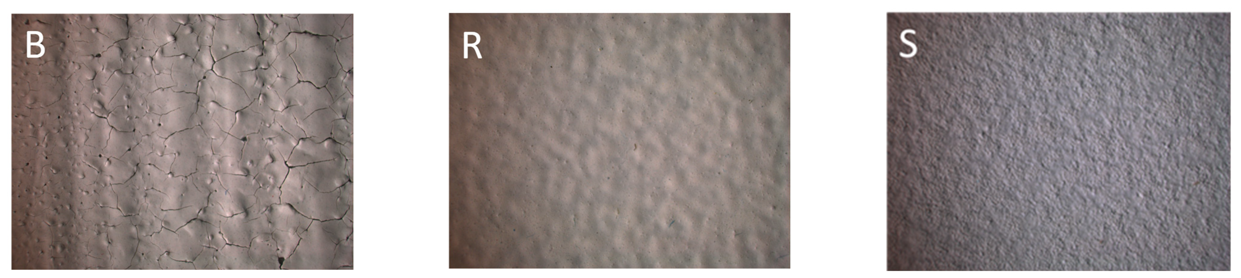
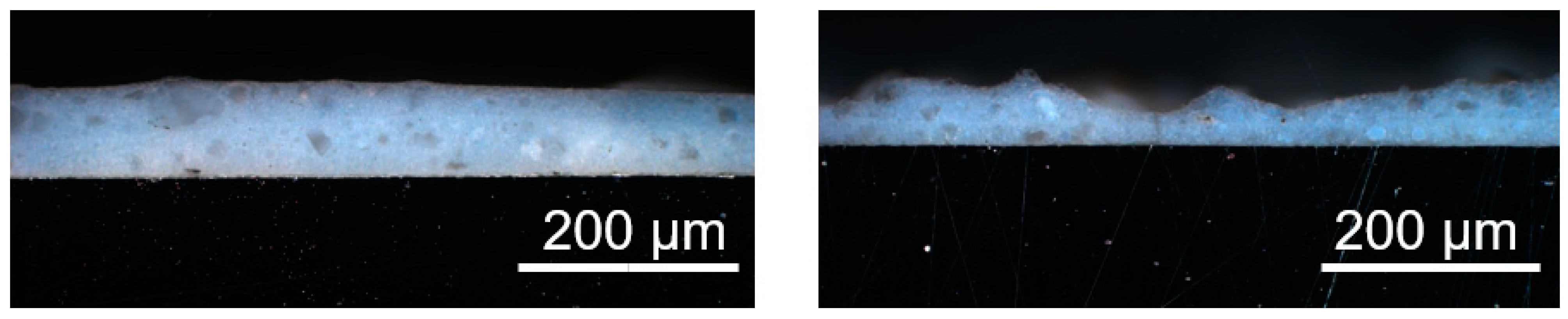
2.2. Optical Properties: Surface and Cross Section

The optical microscope images in Figure 3 clearly show the differences between the coatings applied by brush (B), roller (R) and spray gun (S) with an additional 24 h of air drying. The brush process (visible vertical stroke) resulted in a coating with inhomogeneous thickness, weak adhesion, high porosity and a lot of cracks. Variation in the coating thickness evidently led to non-uniform drying and crack formation where the layers were thicker. Due to the surface inhomogeneities and the weak coating adhesion, the brush process will not be further investigated.
For samples R and S, a uniformly structured and homogenous surface is shown. No cracks or defects are visible. Sample S seems to have a smoother surface sample than R. Methods S and R were identified as suitable for application of the catalytic coatings.
The SEM images in Figure 4 show the surface structure of the coatings 2-R at high resolution. Agglomerates of nanometric TiO2 powder are distributed between the spherical particles of the geopolymer matrix. The cured composite mixture apparently contains a considerable amount of porosity. The structure of the 2-S coating (not shown) looks almost identical.
The optical images of the cross-section of both coatings in Figure 5 clearly show distinct differences between samples R (left) and S (right). The sprayed coating exhibits an uneven thickness and much greater variability compared to the roller coating. Despite the difference in thickness and variation, both coatings were successfully applied over the entire substrate without any continuous cracks detected from the top to the bottom at this magnification. The sprayed layer is thinner than the rolled coating in the thickest areas. If necessary, this could be compensated by applying additional spray gun passes. The optical images do not indicate any discernible differences in the individual particles within the coating structure of the two samples. However, further information regarding particle distribution can be found in the EDX measurements discussed in the following section.

2.3. EDX (Energy-Dispersive X-ray Spectroscopy)

Due to the amorphous signals of the XRD measurements of the coatings, EDX measurements were carried out to identify the distribution of individual components. EDX measurements of a surface and cross-section of an R coating are shown in Figure 6 and Figure 7. The cross-sectional EDX measurement presented in Figure 7 was performed only for the sprayed sample, as the coating composition for both rolled and sprayed samples is identical.
Next to the SEM image, the same section is always shown in a different color depending on the investigated element. The more intense the color, the higher the local concentration of the element. The elements of the potassium water glass, such as K, Al, Ca, Si and O, can be identified in addition to Ti in the cross section. The elements titanium, oxygen and potassium are homogenously distributed in the coating compared to silicon, alumina and calcium. Potassium is only present to a very small content, as the data stand out weakly from the background noise of the measurement. The coating consists mainly of silica, which is distributed as fine particles almost everywhere except in the areas with large non-spherical particles. Aluminum and calcium, on the other hand, are mainly found in bulky grains and at high concentration in the aluminum substrate (intense red color). Titanium is homogeneously distributed and does not show any highly concentrated areas or sedimentation in the coating. All colored points outside of the coating or the substrate are due to background noise of the measurement.
The distribution and quantity of TiO2 on the coating surface are assumed to have a direct impact on the photocatalytic activity. Therefore, to establish a correlation between TiO2 distribution and amount with the degradation curves of methylene blue, both rolled and sprayed samples were examined using EDX. The EDX measurement of the surface for sample S is presented in Figure 7 (sample R is similar) and shows the uniform dispersion and distribution of titanium on the surface. The results reveal that titanium is well dispersed between the spherical water glass matrix, as seen in Figure 7. This result is not surprising, as the coatings are based on mixtures prepared under identical conditions and only differ in the coating procedure.

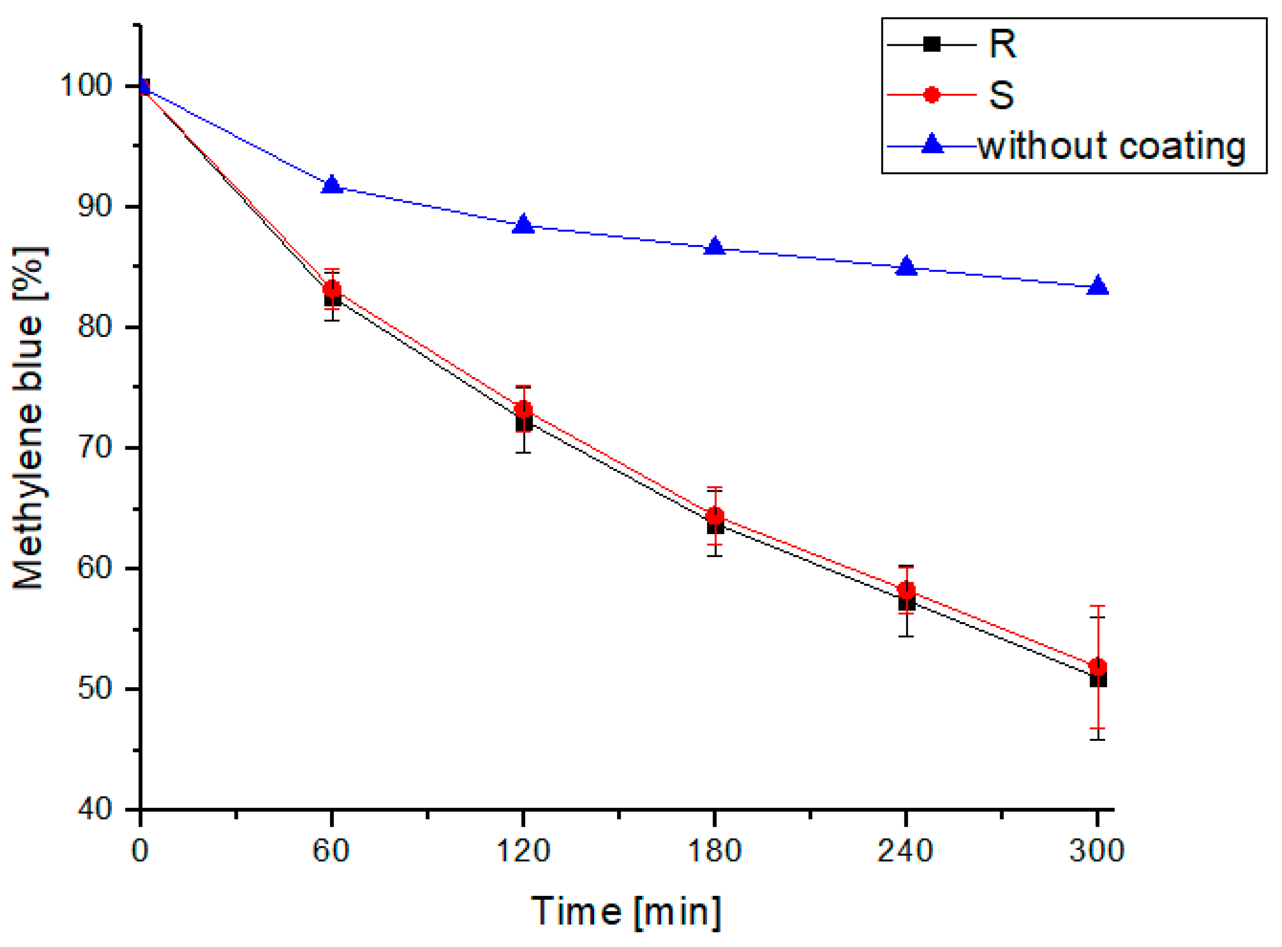
2.4. Photocatalytic Activity

Figure 8 shows the degradation curves of methylene blue concentration over time for the roller and the sprayed coatings compared to a reference (uncoated aluminum sheet). For R and S, approximately 50% of the initial concentration was degraded after 5 h. Both curves demonstrate a similar degradation rate, with no significant difference. This is expected since, for both samples, the same coating composition was used and the surface morphology was also very similar, as shown in Figure 4 and Figure 7. For each coating, the experiment was repeated three times (n = 3). Figure 8 shows the mean values for each coating and the error bars, calculated by the standard deviation of the three measurements. Due to the experimental setup, a lot of variables influence the measurements (positioning of the reactor chutes, proceeding deviation of the spectrometer from initial calibration, adjustment of concentrations) which may explain the high errors, especially at long exposition times. However, with regard to the degradation kinetics, there was no recognizable or noticeable tendency of catalyst de-activation. This indicates that the two coating techniques do not affect the degradation kinetics for this particular test setup.

3. Discussion

It is shown that well-adhering and homogeneous coatings of titania-doped geopolymer can be applied using simple and efficient procedures. The method of pre-mixing commercially available potassium silicate/hardener mixtures with a photocatalytically active titania filler leads to homogeneous coatings. Brush coatings were inhomogeneous, while roller and spray coating—despite some variations in coating thickness—led to coatings of identical microstructure and final photocatalytic activity.
Characterization of the coatings by XRD revealed that the components of the commercially available geopolymer and the titania dispersion show considerable overlap, so the phase distribution of anatase and rutile in the final coating cannot be determined. Moreover, we may speculate that the commercially available water glass system contains further unspecified and proprietary constituents which imped the analysis of the systems by XRD. Rutile disappears in the background and anatase is only seen as a shoulder of the CaAl2O4 peak (or vice versa).
SEM images in combination with EDX measurements confirm the homogeneous distribution of titania agglomerates is a coarser geopolymer matrix consisting of globular particles. The geopolymer matrix builds up a homogeneous yet porous microstructure in which large bulky calcium aluminate particles are dispersed. The titania does not segregate or sediment. Slight intensity fluctuations of titanium occur due to the agglomerated nature of the powder and the low-intensity mixing process, which is not capable of de-agglomerating the titania.
Roller coating provides thicker layers and more homogeneous thickness than spray coatings. As can be seen from the methylene blue degradation experiments, this obviously has no influence on the catalytic activity. (Brushed coatings were too inhomogeneous to adhere safely to the substrate), A priori, we may assume that only the surface near titania contributes to the photocatalytic effect and that the contribution of titania in the bulk is negligible. Application of thicker coatings is presumably not necessary so that the area concentration rather than the total amount of titania is relevant for catalysis.
A direct comparison of the catalytic activity with existing publications is difficult due to the different experimental set-ups. However, the amount of recirculated methylene blue solution is quite high and the difference from the reference measurement (UV radiation alone) is significant.
Points worth clarifying in upcoming studies will be to verify the above hypothesis and check the effects of different coating thicknesses’ titania contents and the effect of dispersion quality (titania agglomerates vs. isolated particles). With respect to titania retention in the coatings (nanoparticles should not be washed out into the purified water), agglomerates may prove the better solution provided that their activity is comparable.

4. Materials and Methods

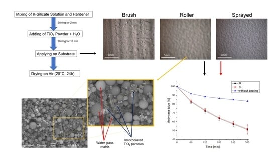
4.1. Application of Photocatalytic Coatings

In this study, P25-TiO2 (Evonik Industries AG, Essen, Germany) powder, a material with a proven track record in photocatalysis, was used. The basic workflow is shown in Figure 9. To create the catalyst coatings, P25-TiO2 powder dispersed in a commercially available potassium silicate solution was applied directly to aluminum substrate. The solution consists of a modified aluminosilicate and modified alkali silicates, so-called “water glass”, provided by Woellner GmbH, Ludwigshafen, Germany. The potassium silicate solution (Geosil14517, Woellner GmbH, Ludwigshafen am Rhein, Germany) and hardener (Stabisil40, Woellner GmbH, Ludwigshafen am Rhein, Germany) were mixed in a ratio of 2:5 and 5.7 wt.% TiO2 was added. For better processing, small amounts of water were added to the suspension. The suspension was then stirred for 10 min using a magnetic stirrer (300 rpm). The resulting suspensions were the coated onto aluminum substrates (100 mm × 100 mm × 4 mm). The coatings were left to dry in air (at room temperature ~25 °C) for 24 h, allowing any remaining water to slowly evaporate.
Commercially available brushes and rollers were used for the coating process. The coatings were carefully applied by hand, ensuring that they are as thin as possible and covering the entire substrate. A spray gun (Binks 95 Manual Spray Gun, Carlisle Fluid Technologies, Scottsdale, AZ, USA) was used for the spraying process. The spraying process was carried out at an air pressure of 2 bar from a distance of 20 cm until the substrate was completely covered (the denomination of the processes is listed in Table 2).

4.2. Powder and Coating Characterization

4.2.1. X-ray Diffraction (XRD)

The phase compositions of the untreated TiO2 powders were analyzed using X-Ray diffraction (XRD) (X’Pert MPD, Panalytical, Almelo, The Netherlands, CuKα1, Ge-monochromator, Bragg–Brentano setup, accelerator detector). Overview scans from 20–70° 2θ were examined to identify and quantify individual components. For TiO2, the 22–32° 2θ range was examined in detail to detect the characteristic anatase and rutile peaks. The volume content of the titania phases was calculated using the calibration curve developed by Vu et al. [49]. The crystallite size of the starting powders was estimated using Scherrer analysis, assuming the absence of residual stress, based on the full width at half maximum of the anatase (101) and rutile (110) peaks using X-Pert MPD Software [50].

4.2.2. SEM, EDX and Optical Microscope

Scanning electron microscopy (SEM) pictures were taken to analyze the surface and cross section of the applied coatings with a Jeol JSM-6490LV microscope (JEOL Ltd., Akishima, Japan). For cross section SEM images, samples were embedded (EpoThin 2 (Buehler, Leinfeld-Echterdingen, Germany)), ground and polished (Struers, Willich, Germany). For the optical characterization, samples were examined with a Leica DMRP microscope (Leica Microsystems GmbH, Wetzlar, Germany).
For EDX (Energy-dispersive X-ray spectroscopy) a SEM Hitachi TM4000Plus II (Chiyoda, Japan) connected to an EDX spectroscope from Oxford Instruments Aztec EDS (Abingdon, UK) was used.

4.3. Photocatalytic Activity

A batch process reactor with a test volume of 500 mL methylene blue solution (10 µmol/L) was used to determine the photocatalytic activity of the applied catalyst coatings. The reactor’s outflow was collected in a storage tank, which was connected to the reactor’s inlet via a peristaltic pump. The fluid was circulated at a flow rate of 40 mL/min and illuminated with UV-A radiation under laboratory conditions for a duration of 300 min. The 2 × 15 W UV-A lamp, emitting radiation at a wavelength of 365 nm (VL-215.BL, Vilber, Marne-la-Vallée, France) was placed 100 mm above the coating. To achieve methylene blue adsorption equilibrium, the solution was circulated 15 min in the dark prior to testing. Subsequently, the UV-A light and sampling (every 60 min/sample) started. The degradation of methylene blue solution under irradiation was evaluated at the characteristic peak of 664 nm in the absorption spectra [51]. Each sample was analyzed using a UV-Vis spectrometer (Specord 210 Plus of Analytik Jena, Jena, Germany) and then returned to the experiment. Measurements were repeated three times for every catalyst sample.

5. Conclusions

This study presents two coating techniques used to produce highly active TiO2 catalyst coatings based on geopolymers on aluminum substrate. The roller coating process is simple and allows for quick coating of large flat surfaces, while the spray gun process is slightly more complex but allows for easy industrial upscaling and coating of complex substrates. Both processes save a lot of energy compared to other coating technologies, as they are carried out at room temperature and do not require subsequent thermal treatments for drying or phase formation. The TiO2 agglomerates are well dispersed in the geopolymer matrix and are present in sufficient quantities at the surface of the coating, leading to a high photocatalytic activity of the coating. The thick coatings (~100 µm) do not exhibit corrosion due to photocatalytic oxidation, since the geopolymers are mineral based. Residual alkaline reaction products which may corrode the aluminum substrate will be washed out successively during operation.
These results show that the potassium water glass material system holds great potential for the sustainable and cheap production of photocatalytic coatings, which are required for environmental applications such as wastewater and air treatment. Future research should evaluate the use of these coatings in experimental reactors for water and wastewater treatment, as well as long-term experiments to assess their reliability.

Author Contributions

Conceptualization, L.D. and F.O.; Methodology, L.D., F.O. and T.L.; Validation, T.L. and F.K.; Formal analysis, L.D., F.O. and T.L.; Investigation, L.D., F.O. and T.L.; Data curation, F.O. and N.O.; Writing—original draft, L.D.; Writing—review & editing, N.O. and F.K.; Visualization, L.D.; Supervision, N.O. and F.K. All authors have read and agreed to the published version of the manuscript.

Funding

This project was funded by Vector Stiftung (P2020-0129), Stuttgart. This publication was funded by the German Research Foundation (DFG) grant “Open Access Publication Funding/2023–2024/University of Stuttgart” (512689491).

Data Availability Statement

The datasets generated and/or analyzed during the current study are available from the corresponding author on reasonable request.

Acknowledgments

We would like to thank Dipl. Ing. Andreas Vogel and Willi Schwan for their technical support and the interesting discussions about the results.

Conflicts of Interest

The authors declare no conflict of interest.

References

  1. Ismael, M. A review and recent advances in solar-to-hydrogen energy conversion based on photocatalytic water splitting over doped-TiO2 nanoparticles. Sol. Energy 2020, 211, 522–546. [Google Scholar] [CrossRef]
  2. Omar, A.; Ali, M.S.; Abd Rahim, N. Electron transport properties analysis of titanium dioxide dye-sensitized solar cells (TiO2-DSSCs) based natural dyes using electrochemical impedance spectroscopy concept: A review. Sol. Energy 2020, 207, 1088–1121. [Google Scholar] [CrossRef]
  3. Ochiai, T.; Fujishima, A. Photoelectrochemical properties of TiO2 photocatalyst and its applications for environmental purification. J. Photochem. Photobiol. C Photochem. Rev. 2012, 13, 247–262. [Google Scholar] [CrossRef]
  4. Schoenell, E.K.; Otto, N.; Rodrigues, M.A.S.; Metzger, J.W. Removal of Organic Micropollutants from Treated Municipal Wastewater by O3/UV/H2O2 in a UVA-LED Reactor. Ozone Sci. Eng. 2022, 44, 172–181. [Google Scholar] [CrossRef]
  5. Dionysiou, D.D.; Bahnemann, D.; Puma, G.L.; Ye, J.; Schneider, J. (Eds.) Photocatalysis: Applications; Royal Society of Chemistry: Cambridge, UK, 2016; ISBN 978-1-78262-709-8. [Google Scholar]
  6. Pichat, P. (Ed.) Photocatalysis and Water Purification: From Fundamentals to Recent Applications; Wiley-VCH-Verl: Weinheim, Germany, 2013; ISBN 978-3-527-33187-1. [Google Scholar]
  7. Schneider, J.; Bahnemann, D.; Ye, J.; Li Puma, G.; Dionysiou, D.D. (Eds.) Photocatalysis; Royal Society of Chemistry: Cambridge, UK, 2016; ISBN 978-1-78262-041-9. [Google Scholar]
  8. Bojinova, A.; Kralchevska, R.; Poulios, I.; Dushkin, C. Anatase/rutile TiO2 composites: Influence of the mixing ratio on the photocatalytic degradation of Malachite Green and Orange II in slurry. Mater. Chem. Phys. 2007, 106, 187–192. [Google Scholar] [CrossRef]
  9. Zaleska, A. Doped-TiO2: A Review. ENG 2008, 2, 157–164. [Google Scholar] [CrossRef]
  10. Ollis, D.F.; Al-Ekabi, H. (Eds.) Photocatalytic Purification and Treatment of Water and Air: Proceedings of the 1st International Conference on TiO2 Photocatalytic Purification and Treatment of Water and Air, London, ON, Canada, 8–13 November 1992; Elsevier Science Limited: Amsterdam, The Netherlands, 1993. [Google Scholar]
  11. Mills, A.; Le Hunte, S. An overview of semiconductor photocatalysis. J. Photochem. Photobiol. A Chem. 1997, 108, 1–35. [Google Scholar] [CrossRef]
  12. Ide, Y.; Inami, N.; Hattori, H.; Saito, K.; Sohmiya, M.; Tsunoji, N.; Komaguchi, K.; Sano, T.; Bando, Y.; Golberg, D.; et al. Remarkable Charge Separation and Photocatalytic Efficiency Enhancement through Interconnection of TiO2 Nanoparticles by Hydrothermal Treatment. Angew. Chem. Int. Ed. Engl. 2016, 55, 3600–3605. [Google Scholar] [CrossRef]
  13. Ohtani, B.; Prieto-Mahaney, O.O.; Li, D.; Abe, R. What is Degussa (Evonik) P25? Crystalline composition analysis, reconstruction from isolated pure particles and photocatalytic activity test. J. Photochem. Photobiol. A Chem. 2010, 216, 179–182. [Google Scholar] [CrossRef]
  14. Tobaldi, D.M.; Pullar, R.C.; Seabra, M.P.; Labrincha, J.A. Fully quantitative X-ray characterisation of Evonik Aeroxide TiO2 P25®. Mater. Lett. 2014, 122, 345–347. [Google Scholar] [CrossRef]
  15. Salkic, S.; Eckler, L.H.; Nee, M.J. Noninvasive monitoring of photocatalytic degradation of X-ray contrast media using Raman spectrometry. J. Raman Spectrosc. 2013, 44, 1746–1752. [Google Scholar] [CrossRef]
  16. Rachel, A.; Subrahmanyam, M.; Boule, P. Comparison of photocatalytic efficiencies of TiO2 in suspended and immobilised form for the photocatalytic degradation of nitrobenzenesulfonic acids. Appl. Catal. B Environ. 2002, 37, 301–308. [Google Scholar] [CrossRef]
  17. Cohen-Yaniv, V.; Narkis, N.; Armon, R. Photocatalytic inactivation of Flavobacterium and E. coli in water by a continuous stirred tank reactor (CSTR) fed with suspended/immobilised TiO2 medium. Water Sci. Technol. 2008, 58, 247–252. [Google Scholar] [CrossRef] [PubMed]
  18. Pozzo, R.L.; Baltanás, M.A.; Cassano, A.E. Supported titanium oxide as photocatalyst in water decontamination: State of the art. Catal. Today 1997, 39, 219–231. [Google Scholar] [CrossRef]
  19. Singh, S.; Mahalingam, H.; Singh, P.K. Polymer-supported titanium dioxide photocatalysts for environmental remediation: A review. Appl. Catal. A Gen. 2013, 462, 178–195. [Google Scholar] [CrossRef]
  20. Espíndola, J.C.; Cristóvão, R.O.; Mendes, A.; Boaventura, R.A.; Vilar, V.J. Photocatalytic membrane reactor performance towards oxytetracycline removal from synthetic and real matrices: Suspended vs immobilized TiO2-P25. Chem. Eng. J. 2019, 378, 122114. [Google Scholar] [CrossRef]
  21. Alrousan, D.; Polo-López, M.I.; Dunlop, P.; Fernández-Ibáñez, P.; Byrne, J.A. Solar photocatalytic disinfection of water with immobilised titanium dioxide in re-circulating flow CPC reactors. Appl. Catal. B Environ. 2012, 128, 126–134. [Google Scholar] [CrossRef]
  22. Khan, S.J.; Reed, R.H.; Rasul, M.G. Thin-film fixed-bed reactor for solar photocatalytic inactivation of Aeromonas hydrophila: Influence of water quality. BMC Microbiol. 2012, 12, 285. [Google Scholar] [CrossRef]
  23. Mehos, M.S.; Turchi, C.S. Field testing solar photocatalytic detoxification on TCE-contaminated groundwater. Environ. Prog. 1993, 12, 194–199. [Google Scholar] [CrossRef]
  24. Oelgemöller, M.; Healy, N.; de Oliveira, L.; Jung, C.; Mattay, J. Green photochemistry: Solar-chemical synthesis of Juglone with medium concentrated sunlight. Green Chem. 2006, 8, 831–834. [Google Scholar] [CrossRef]
  25. Martín-Sómer, M.; Moreno-SanSegundo, J.; Álvarez-Fernández, C.; van Grieken, R.; Marugán, J. High-performance low-cost solar collectors for water treatment fabricated with recycled materials, open-source hardware and 3d-printing technologies. Sci. Total Environ. 2021, 784, 147119. [Google Scholar] [CrossRef] [PubMed]
  26. Akpan, U.G.; Hameed, B.H. The advancements in sol–gel method of doped-TiO2 photocatalysts. Appl. Catal. A Gen. 2010, 375, 1–11. [Google Scholar] [CrossRef]
  27. Arconada, N.; Durán, A.; Suárez, S.; Portela, R.; Coronado, J.M.; Sánchez, B.; Castro, Y. Synthesis and photocatalytic properties of dense and porous TiO2-anatase thin films prepared by sol–gel. Appl. Catal. B Environ. 2009, 86, 1–7. [Google Scholar] [CrossRef]
  28. Toma, F.-L.; Bertrand, G.; Klein, D.; Meunier, C.; Begin, S. Development of Photocatalytic Active TiO2 Surfaces by Thermal Spraying of Nanopowders. J. Nanomater. 2008, 2008, 1–8. [Google Scholar] [CrossRef]
  29. Toma, F.; Bertrand, G.; Begin, S.; Meunier, C.; Barres, O.; Klein, D.; Coddet, C. Microstructure and environmental functionalities of TiO2-supported photocatalysts obtained by suspension plasma spraying. Appl. Catal. B Environ. 2006, 68, 74–84. [Google Scholar] [CrossRef]
  30. Toma, F.-L.; Bertrand, G.; Klein, D.; Coddet, C.; Meunier, C. Nanostructured Photocatalytic Titania Coatings Formed by Suspension Plasma Spraying. J. Therm. Spray Tech. 2006, 15, 587–592. [Google Scholar] [CrossRef]
  31. Bolelli, G.; Cannillo, V.; Gadow, R.; Killinger, A.; Lusvarghi, L.; Rauch, J. Properties of High Velocity Suspension Flame Sprayed (HVSFS) TiO2 coatings. Surf. Coat. Technol. 2009, 203, 1722–1732. [Google Scholar] [CrossRef]
  32. Zhang, X.; Zhou, M.; Lei, L. Preparation of anatase TiO2 supported on alumina by different metal organic chemical vapor deposition methods. Appl. Catal. A Gen. 2005, 282, 285–293. [Google Scholar] [CrossRef]
  33. Kim, B.-H.; Lee, J.-Y.; Choa, Y.-H.; Higuchi, M.; Mizutani, N. Preparation of TiO2 thin film by liquid sprayed mist CVD method. Mater. Sci. Eng. B 2004, 107, 289–294. [Google Scholar] [CrossRef]
  34. Ghorai, T.K.; Dhak, D.; Biswas, S.K.; Dalai, S.; Pramanik, P. Photocatalytic oxidation of organic dyes by nano-sized metal molybdate incorporated titanium dioxide (MxMoxTi1−xO6) (M=Ni, Cu, Zn) photocatalysts. J. Mol. Catal. A Chem. 2007, 273, 224–229. [Google Scholar] [CrossRef]
  35. Babelon, P.; Dequiedt, A.; Mostéfa-Sba, H.; Bourgeois, S.; Sibillot, P.; Sacilotti, M. SEM and XPS studies of titanium dioxide thin films grown by MOCVD. Thin Solid Film. 1998, 322, 63–67. [Google Scholar] [CrossRef]
  36. Karuppuchamy, S.; Suzuki, N.; Ito, S.; Endo, T. A novel one-step electrochemical method to obtain crystalline titanium dioxide films at low temperature. Curr. Appl. Phys. 2009, 9, 243–248. [Google Scholar] [CrossRef]
  37. Robayo-Salazar, R.A.; Mejía-Arcila, J.M.; Mejía de Gutiérrez, R. Eco-efficient alkali-activated cement based on red clay brick wastes suitable for the manufacturing of building materials. J. Clean. Prod. 2017, 166, 242–252. [Google Scholar] [CrossRef]
  38. Provis, J.L.; van Deventer, J.S.J. Geopolymers; Elsevier: Amsterdam, The Netherlands, 2009; ISBN 9781845694494. [Google Scholar]
  39. McLellan, B.C.; Williams, R.P.; Lay, J.; van Riessen, A.; Corder, G.D. Costs and carbon emissions for geopolymer pastes in comparison to ordinary portland cement. J. Clean. Prod. 2011, 19, 1080–1090. [Google Scholar] [CrossRef]
  40. Fujishima, A.; Zhang, X.; Tryk, D. TiO2 photocatalysis and related surface phenomena. Surf. Sci. Rep. 2008, 63, 515–582. [Google Scholar] [CrossRef]
  41. Pacheco Torgal, F.; Jalali, S. Eco-Efficient Construction and Building Materials; Springer: London, UK, 2011; ISBN 978-0-85729-892-8. [Google Scholar]
  42. Mao, Y.; Biasetto, L.; Colombo, P. Metakaolin-based geopolymer coatings on metals by airbrush spray deposition. J. Coat Technol. Res. 2020, 17, 991–1002. [Google Scholar] [CrossRef]
  43. Zheng, K.; Chen, L.; Gbozee, M. Thermal stability of geopolymers used as supporting materials for TiO2 film coating through sol-gel process: Feasibility and improvement. Constr. Build. Mater. 2016, 125, 1114–1126. [Google Scholar] [CrossRef]
  44. Strini, A.; Roviello, G.; Ricciotti, L.; Ferone, C.; Messina, F.; Schiavi, L.; Corsaro, D.; Cioffi, R. TiO₂-Based Photocatalytic Geopolymers for Nitric Oxide Degradation. Materials 2016, 9, 513. [Google Scholar] [CrossRef]
  45. Otto, N. Evaluierung Eines UV-A-LED Paneelreaktorkonzepts für Photo-Oxidationsverfahren in der (Ab-) Wasserreinigung; Forschungs- und Entwicklungsinstitut für Industrie- und Siedlungswasserbau e.V.: Stuttgart, Germany, 2022. [Google Scholar]
  46. Din, M.I.; Khalid, R.; Najeeb, J.; Hussain, Z. Fundamentals and photocatalysis of methylene blue dye using various nanocatalytic assemblies- a critical review. J. Clean. Prod. 2021, 298, 126567. [Google Scholar] [CrossRef]
  47. Lachheb, H.; Puzenat, E.; Houas, A.; Ksibi, M.; Elaloui, E.; Guillard, C.; Herrmann, J.-M. Photocatalytic degradation of various types of dyes (Alizarin S, Crocein Orange G, Methyl Red, Congo Red, Methylene Blue) in water by UV-irradiated titania. Appl. Catal. B Environ. 2002, 39, 75–90. [Google Scholar] [CrossRef]
  48. Hindryawati, N.; Maniam, G.P.; Karim, M.R.; Chong, K.F. Transesterification of used cooking oil over alkali metal (Li, Na, K) supported rice husk silica as potential solid base catalyst. Eng. Sci. Technol. Int. J. 2014, 17, 95–103. [Google Scholar] [CrossRef]
  49. Vu, P.; Otto, N.; Vogel, A.; Kern, F.; Killinger, A.; Gadow, R. Efficiently quantifying the anatase content and investigating its effect on the photocatalytic activity of titania coatings by suspension plasma spraying. Surf. Coat. Technol. 2019, 371, 117–123. [Google Scholar] [CrossRef]
  50. Patterson, A.L. The Scherrer Formula for X-Ray Particle Size Determination. Phys. Rev. 1939, 56, 978–982. [Google Scholar] [CrossRef]
  51. Deutsches Institut für Normung. Photocatalytic Activity of Surfaces-Determination of Photocatalytic Activity by Degradation of Methylene Blue: DIN 52980. Beuth, 2008 (52980). Available online: https://www.beuth.de/de/norm/din-52980/110195678 (accessed on 1 February 2023).
Figure 1. XRD pattern of raw materials and its combination in the area from 20–70°. A = Anatase, R = Rutile, C1 = CaAl2O4, C2 = CaAl4O7.
Catalysts 13 00898 g001
Figure 2. XRD pattern of all data in the characteristic area (22–32°) to identify the characteristic peaks of TiO2 anatase and rutile phase. A = Anatase, R = Rutile, C1 = CaAl2O4, C2 = CaAl4O7.
Catalysts 13 00898 g002
Figure 3. Optical micrographs of surface structure of applied coatings by different coating processes (B, R and S).
Catalysts 13 00898 g003
Figure 4. SEM images of nanostructured surface of sample R.
Catalysts 13 00898 g004
Figure 5. Optical micrographs of polished cross section of sample R (left) and S (right).
Catalysts 13 00898 g005
Figure 6. SEM and corresponding EDX image of a coating achieved via roller process (cross section).
Catalysts 13 00898 g006
Figure 7. SEM image of catalyst surface area (left) and the corresponding EDX measurement (right) for titania, shown for the sample S.
Catalysts 13 00898 g007
Figure 8. Degradation of methylene blue over time without catalyst coating (blue), roller process coating (black) and spray coating (red).
Catalysts 13 00898 g008
Figure 9. Visualization of the coating process.
Catalysts 13 00898 g009
Table 1. Calculated Crystallite size and phase content of the P25 powder.
P25-TiO2Crystallite Size [nm]Phase Content [%]
Anatase21.987.4
Rutile41.012.6
Table 2. Denomination of coating processes.
Sample NameCoating Process
BApplication with a paint brush
RApplication with a roller
SApplication with a spray gun
Disclaimer/Publisher’s Note: The statements, opinions and data contained in all publications are solely those of the individual author(s) and contributor(s) and not of MDPI and/or the editor(s). MDPI and/or the editor(s) disclaim responsibility for any injury to people or property resulting from any ideas, methods, instructions or products referred to in the content.

