Article

Tailoring CoNi Alloy-Embedded Carbon Nanofibers by Coaxial Electrospinning for an Enhanced Oxygen Reduction Reaction

School of Materials Science & Engineering, International S&T Cooperation Foundation of Shaanxi Province, Shaanxi University of Science and Technology, Xi’an 710021, China
*
Authors to whom correspondence should be addressed.
Catalysts 2023, 13(5), 890; https://doi.org/10.3390/catal13050890
Submission received: 22 March 2023 / Revised: 26 April 2023 / Accepted: 5 May 2023 / Published: 15 May 2023

Abstract

:
A flexible CoNi@CNF electrochemical catalyst was developed using coaxial electrostatic spinning technology. The distribution and content of CoNi alloy nanoparticles on the surface of carbon fibers were adjusted by regulating the feed speed ratio of the outer and inner axes of coaxial electrostatic spinning. The results indicate that the content of the CoNi alloy distributed on the carbon fiber surface increased from 26.7 wt.% to 38.4 wt.% with an increase in the feed speed of the inner axis. However, the excessive precipitation of the CoNi alloy on the carbon fiber surface leads to the segregation of the internal CoNi alloy, which is unfavorable for the exposure of active sites during the electrolytic reaction. The best electrocatalytic performance of the composite was achieved when the rate of the outer axis feed speed was constant (3 mm/h) and the rate of the inner axis was 1.5 mm/h. The initial oxygen reduction potential and half-slope potential were 0.99 V and 0.92 V (VS RHE), respectively. The diffusion-limited current density was 6.31 mA/cm−2 and the current strength retention was 95.2% after the 20,000 s timed current test.

1. Introduction

As the energy crisis and environmental pollution intensify, the need for developing green electrochemical energy storage and sustainable energy conversion technologies is gradually increasing [1,2,3,4]. Fuel cells have been proved to be promising candidate batteries due to their remarkably theoretical energy density and lack of pollution during use. Nevertheless, their cathodic oxygen reduction reaction (ORR) rate response is extremely low, which significantly limits the production of oxygen reduction active species and reduces their energy conversion efficiency [5,6,7,8]. In addition, the high cost, low storage and low durability of platinum and other precious metals as catalyst materials dramatically limit the commercial utility of fuel cells [9]. Therefore, the process of developing low-cost, stable active, non-precious metal catalysts for catalytic cathodic oxygen reduction reactions is beneficial to promote the development of fuel cells, thus making it possible to apply them commercially on a large scale [10,11,12].
Among the different types of candidate materials, most of the studies on non-Platinum catalysts have focused on transition metal and carbon materials for morphology modulation as well as heteroatom doping [13,14]. On the one hand, nano-sized crystal structures of transition metals are constructed to improve the catalytic activity, and on the other hand, heteroatom-doped carbon materials are used to improve the stability [15,16,17]. Alloying and hybridization strategies are the main approaches to improve the performance of transition metal catalysts. Alloyed materials with combinations of two or more metals give the materials better electrocatalytic properties due to their increased real surface area and intrinsic activity [18,19]. Hybridization utilizes the inherent activity of transition metals and the excellent conductivity, easy surface functionalization and great stability of carbon materials to further improve the electrocatalytic activity [20,21,22,23]. Bimetallic alloy nanoparticles (e.g., FeNi, FeCo, MnNi and NiCo) are also active for electrocatalytic reactions because the electronic properties of individual atoms are significantly influenced by neighboring atoms. Among them, nickel and cobalt are abundant on Earth and have promising applications in bimetallic alloys due to their abundant valence changes and high catalytic activity. Javier et al. [24] synthesized C1N1 material and introduced TM atoms, denoted as TM@CNx, where TM is either Fe, Co, Cu, Ni or Mn and x is the C/N atomic ratio of the resulting material. Compared to the electrocatalyst performance with commercial benchmark catalysts (Pt/C and IrO2), the results showed that the Co@CNx is the most promising for HER due to the high catalytic performance of a single CoNx atom, and the EHER is −0.27 V, close to the commercial Pt/C electrocatalyst. Fu et al. [25] reported NiCo alloy-anchored N-doped CNF heterogeneous catalysts (NiCo@N-C) prepared by simple electrostatic spinning and heat treatment. The loading of NiCo alloy nanoparticles could be well adjusted by varying the content of nickel and cobalt salts. Carbon nanofibers (CNF) stand out from other carbon material carriers due to their distinctive one-dimensional structure that facilitates electron transport and mass diffusion. Moreover, nanofibers can give the material good flexibility and tensile ability due to their large aspect ratio, which improves the resistance of the material. Additionally, the larger specific surface area of one-dimensional nanostructures facilitates the exposure of more active sites [26,27,28,29,30]. Thus, nanofiber-based carriers can confer enhanced activity, selectivity, durability, and stability to immobilized catalysts. Li et al. [31] synthesized the structure of Ni3Co nanoparticles modified with layered porous N-CNTs grafted onto CNF membrane (Ni1.5Co0.5@N-CNT/NFs). The optimized catalysts have a low OER overpotential of 243 mV for 10 mA cm−2 overpotential. Lu et al. [32] embedded RuNi nanoparticles into N-CNFs to obtain Ru1Ni1-NCNFs, which also demonstrated excellent OER performance with a low overpotential of 290 mV at 10 mA cm−2. Liu et al. [33] synthesized a trimetallic FeCoNi-N/CNF electrocatalyst that exhibited good electrocatalytic ORR activity and stability in 0.5 M H2SO4. Lei et al. [34] prepared a CoFe-Co@PNC bifunctional oxygen electrocatalyst by annealed SiO2 coated zeolite imidazolate framework-67 (ZIF-67) encapsulate Fe ions. The overpotential of OER is only 320 mV at 0 mA·cm−2, and the half-wave potential of ORR is 0.887 V. Chen et al. [35] designed and constructed nitrogen-doped carbon-coupled FeNi3 intermetallic compounds (FeNi3@NC) by a super facile method. It exhibits an ultralow overpotential (Eover) of 277 mV at 10 mA/cm2 for OER, and a high half-wave potential (E1/2) of 0.86 V for ORR which outperform commercial Pt/C electrocatalysts. It is known that electrocatalytic reactions are essentially surface-based reactions, so good dispersion of bimetallic alloy particles on the surface of the carbon substrate is the key to determine the high catalytic activity of the surface [24]. However, most of the alloy nanoparticles are inlaid inside the carbon nanofibers, which may prolong the electron transfer pathway on the one hand and may be disadvantageous for the exposure of active sites on the other hand [36,37]. Therefore, the development of a new technique allowing the growth of alloy particles toward the outside of carbon fibers is attractive for improving the efficiency of oxygen reduction reactive substances as well as energy conversion in the ORR process.
To solve the above problem, we propose a novel strategy to adjust the distribution of CoNi alloy nanoparticles embedded in CNF. Here, we used coaxial electrostatic spinning and subsequent heat treatment to prepare CoNi/CNF composites, where the outer axis solution was a mixture of Co and Ni salts with polyacrylonitrile (PAN), and the inner axis was a pure PAN solution. By keeping the coaxial electrostatic spinning outer axis feed speed constant (3 mm/h) and by adjusting the feed speed of the inner axis, the gradient distribution structure of CoNi alloy particles on the carbon fiber from inside to outside was studied, so that a larger number of alloy particles were distributed on the surface of the carbon fiber to study the electrocatalytic activity and stability.

2. Results and Discussion

2.1. Structural and Morphological Characterizations

In the current study, we provide a facile method to manufacture CoNi/CNF materials through coaxial electrospinning technology. The synthesis process of the CoNi/CNF composite was illustrated in Figure 1. First, polyacrylonitrile ((C3H3N) n, PAN, 0.8 g) was added to N, N-dimethylformamide (C3H7NO DMF, 10 mL) and stirred magnetically at 80 °C for 16 h to obtain the inner axis solution. Subsequently, 0.8 g PAN, 2.0 mmol cobalt acetate tetrahydrate(C4H14CoO8) and nickel acetate tetrahydrate (C4H14NiO8) (Co/Ni atomic ratio of 2:1) were dissolved in 10 mL of DMF with continuous stirring for 16 h to obtain the outer axis solution. Then, the obtained viscous solution was transferred into syringe for electrospinning. The distance between the needle and the receiving device was 15 cm, the voltage was set to 17 kV, and the drum speed was 300 r/min. The solution feed speed was fixed at 3 mm/h on the outer axis and 1 mm/h, 1.5 mm/h and 3 mm/h on the inner axis, respectively. After the spinning completed, the obtained fabric were warmed up to 220 °C for 1 h under an air atmosphere at 2 °C min−1 for pre-oxidation, and then carbonization temperature was set at 700 °C and held for 2 h under an N2 atmosphere to achieve the final CoNi/CNFs, respectively, recorded as 3-1, 3-1.5, 3-3.
The phase composition of the three samples was analyzed using X-ray diffraction XRD, as shown in Figure 2. All samples exhibited similar XRD patterns, and a total of four peaks were identified (Figure 2a). The broad diffraction peak at 25° corresponds to the (002) crystal plane of graphitic carbon, and the remaining three distinct diffraction peaks at 44.4°, 51.6° and 76.2° correspond to the (111), (200) and (220) crystal planes of the CoNi alloy according to Co (PDF#15-0806) and Ni (PDF#04-0850) [38], respectively, as face-centered cubic (fcc) structure. It is noteworthy that the synthesized materials have both Co and Ni diffraction peaks shifted to the middle of the metal Co and Ni standard cards, indicating the formation of CoNi alloy nanoparticles [39,40]. Based on the XRD data, the average grain size of the CoNi alloy was calculated by the Scherrer equation, and the results are shown in Figure 2b. The grain size decreases with the decrease in the ratio between the outer and inner axis feed speed. This is because CoNi salt is ejected from the outer axis solution during the electrostatic spinning process, and the inner axis solution is pure PAN, so when the feed speed of the inner axis is changed, it can effectively form the structure of gradient distribution of the CoNi alloy on carbon fiber, and as the feed speed of the inner axis increases, more CoNi alloy tends to be distributed on the surface, and there is a certain reduction in grain size [41].
The surface morphology and microstructure of CoNi/CNF catalysts was revealed by the SEM and TEM images, as shown in Figure 3. The SEM and TEM images indicate that the CoNi/CNF composite was composed of fibers with particle-like material. According to the XRD analysis, this nanoparticle-like material is the CoNi alloy. In addition, these one-dimensional nanofibers form a continuous three-dimensional network structure, and this special structure not only provides rapid channels for electron transport during the electrocatalytic reaction, but also facilitates the enhanced structural modulation of the CoNi/CNF composites and the overall structural stability during the electrocatalytic process [42]. By further observing the high magnification SEM (Figure 3(a1–c1)), it can be seen that the number of CoNi alloys distributed on the fibers increases greatly when the inner axis feed speed increases from 1 mm/h to 3 mm/h.
As observed in the TEM images (Figure 3(a2–c2)), the fiber diameter is approximately 250 nm and the size of the CoNi alloy particles on the fiber is refined from 15 nm to approximately 10 nm and the number is significantly increased. It is noteworthy that with the increase in the internal axis feeding speed, these CoNi alloys are not just distributed on the surface of the carbon fibers, but are semi-embedded, which is an essential contribution to improve the stability in the electrocatalytic process. However, as the internal axis feed speed increases to 3 mm/h, the CoNi alloys distributed on the fiber surface precipitate further outward and there is some reduction in the size of the alloys, while the interior shows biased aggregation (Figure 3(c1,c2)).
In order to investigate the distribution of elements on the surface of carbon fibers, energy-dispersive X-ray (EDS) was used to analyze the Co and Ni content on the surface of carbon nanofibers. The four pictures are C, N, Co, and Ni elements, from which it can be observed that N is evenly divided. Cloth in the whole carbon nanofiber, Co, Ni elements are distributed on the granular matter. Further low, high-resolution transmission electron microscopy (HRTEM) maps show lattice stripes of 0.204 nm and 0.177 nm for the nanoparticles embedded in carbon nanofibers, which are close to the (111) crystal plane (0.1772 nm, PDF#15-0806) and (200) crystal plane (0.1762 nm, PDF#4) of metallic Co or metallic Ni, respectively (Figure 4b,c), which further identifies the granular material distributed on the carbon fibers as the CoNi alloy. Furthermore, it is noteworthy that the embedded CoNi alloy nanoparticles are surrounded by a graphitic carbon layer with a graphitic carbon lattice stripe of 0.36 nm for the (002) crystal plane. Moreover, it has been shown that the graphitic layer structure is also active in the electrocatalytic process and facilitates the structural stability during the reaction.
Figure 5a is the Raman spectrum of the prepared CoNi/CNFs. There are two peaks centered at 1350 cm−1 and 1578 cm−1, which are attributed to the D band and the G band of C atom crystal characteristic peaks [43,44,45,46,47,48,49]. The IG/(ID + IG) value an usually be used to evaluate the graphitization degree of carbon materials, and a larger IG/(ID + IG) value represents the higher degree of graphitization [50]. As shown in Figure 5b, the graphitization increases with the increase in the internal axis advancement rate. The gradient distribution structure of the CoNi alloy on carbon nanofibers is conducive to the improvement of graphitization. When the inner axis feed speed is 1 mm/h, a larger number of particles of the CoNi alloy are distributed in carbon fibers because they are surrounded by carbon, which is not conducive to catalytic graphitization. With the increase in the internal axial feed speed, more CoNi alloy particles appear on the surface of the carbon fiber, which leads to a larger catalytic graphitization volume, so the graphitization degree is improved to a certain extent.
In order to gain further insight into the surface elemental composition and chemical valence of the designed CoNi/CNF catalysts, the samples synthesized at different internal axis feed speeds were tested and characterized using XPS. The split-peak fits of Co2p and Ni2p are presented in Figure 6a–f. From the figures, it can be observed that for Co2p, there are two main peaks in the Co2p3/2 range centered at 781.0 eV, corresponding to Co0 and Co2+, centered at 778.4 eV and 781.0 eV, respectively. Meanwhile, the two peaks in the Co2p1/2 range centered at 793.7 eV, centered at 780.0 eV and 793.7 eV, also correspond to Co0 and Co2+. For Ni2p, there are two main peaks in the Ni2p3/2 range centered at 854.7 eV, centered at 853.2 eV and 855.2 eV, corresponding to Ni0 and Ni2+, respectively, while two peaks in the Ni2p1/2 range centered at 872.2 eV, centered at 870.5 eV and 872.3 eV, corresponding to Ni0 and Ni2+ [51,52,53,54,55]. The C1s orbital (Figure 6g) is deconvolved into three peaks, with large peaks concentrated in 284.7 eV, ascribed to graphitic carbon. The peak at 285.8 eV can be attributed to the C-N bond. The peak at 288.9 eV can be attributed to the C=O bond, The N1s orbital (Figure 6h) is deconvolved into two peaks, the stronger of which can be attributed to pyridine nitrogen and graphite nitrogen at 398.2 eV and 400.97 eV.
It is noteworthy that no metallic Co and Ni were detected when the internal axis feed speed was 1 mm/h. This may be due to the fact that most of the CoNi alloy particles grew inside the carbon fibers, so more Co2+ and Ni2+ plasma states were detected on the surface (Figure 6a,b). With the increase in the internal axis feed speed, the CoNi alloy particles grew to the outside of the carbon nanofiber, and the volume of CoNi alloy particles increased, so the XPS spectra of Co2p and Ni2p showed the appearance of Co0 and Ni0 (Figure 6c,d), which means that the metallic CoNi distributed on the surface of the carbon fiber increased. When the feed speed of the inner axis was increased to 3 mm/h, Co0 was converted to Co2+ because a large number of particles analyzed on the surface of carbon fiber were partially oxidized in the air (Figure 6e,f). The coexistence of Co0, Ni0, Co2+ and Ni2+, as the active sites in the electrocatalytic reaction process, is beneficial to the improvement of electrocatalytic performance [56,57,58,59,60].

2.2. Electrochemical Evaluation of CoNi/CNFs for ORR

The oxygen reduction (ORR) electrocatalytic activity of all CoNi/CNF catalysts synthesized with different internal axis advance rates were evaluated in an O2-saturated 0.1 M KOH solution using a rotating ring disc electrode (RRDE) and compared with a 20% commercial Pt/C catalyst [61]. Firstly, linear scanning voltammograms (LSVs) of the samples were collected, and as revealed in Figure 7a. Unexpectedly, the inner axis feed speed of 1.5 mm/h exhibited good ORR activity with good onset potential (0.99 V), half-wave potential (0.92 V) (vs. RHE) and maximum limiting current density (6.31 mA/cm−2), better than the feed speed 3-1 (0.96 V, 0.88 V, 5.48 mA/cm−2) and feed speed 3-3 (0.98 V, 0.91 V, 6.00 mA/cm−2), and better than 20% commercial Pt/C (0.99 V, 0.89 V, 5.17 mA/cm−2). The excellent oxygen reduction (ORR) performance of the samples synthesized at an endoaxial feed speed of 1.5 mm/h is attributed to their favorable microstructure. The small grain size and large number of CoNi alloys mosaic inside and on the surface of the carbon fibers, which can increase the number of active sites for electrocatalytic reactions, resulting in outstanding electrocatalytic ability. Therefore, only the appropriate rate of internal and external axis advancement can form this special structure. When the internal axis feed speed is overly low (3-1), the formed CoNi alloy particles are continuously wrapped by the carbon fiber, making it difficult to expose the CoNi alloy particles to the fiber surface, which is not conducive to participate in the electrocatalytic reaction; when the internal axis advancement rate is too large (3-3), the CoNi alloy particles tend to grow on the fiber surface. The distribution of excessive alloy particles on the fiber surface makes the transport path blocked and the electrocatalytic performance slightly decreased. During the ORR process, the synthesized samples were tested by rotating the ring-disk electrode (RRDE) and the ring and disk currents were collected to calculate the electron transfer number (n) and the percentage of hydrogen peroxide (H2O2%) to uncover the reaction path of electrocatalytic oxygen reduction, as shown in Figure 7b. In the potential range between 0.3 and 0.8 V, the samples synthesized with 3-1.5 and 3-3 outer-internal axis advancement rates exhibit similar electron transfer numbers (n) and hydrogen peroxide percentages (H2O2%) in the tested range, with electron transfer numbers around 3.97 and hydrogen peroxide percentages around 5%, outperforming the samples synthesized with 3-1 outer-internal axis advancement rates. The oxygen was directly generated to OH by 4e transfer, and there were fewer intermediate reaction courses, showing superior ORR selectivity and efficient 4e transfer mechanism. The high and stable electron transfer values suggest that the ORR process follows an approximate four-electron pathway over a wide range of potentials [1,62]. Next, to further demonstrate the catalytic pathway of electrocatalytic oxygen reduction, LSV curves and corresponding Koutecky-Levich (K-L) curves were tested for CoNi/CNF catalysts with external and internal axis feed speed of 3-1.5 synthesis at different rotational speeds (400 rpm, 625 rpm, 900 rpm, 1225 rpm, 1600 rpm) as shown in Figure 7c. The Koutecky-Levich (K-L) curves at different potentials inserted in Figure 7c exhibit parallel linear correlation plots indicating the first-order reaction kinetics to oxygen dissolved in the electrolyte, suggesting that the electron transfer rate is independent of the potential. Based on the K-L equation, the electron transfer number (n) was determined to be 3.98, indicating the dominance of the four-electron pathway in the ORR, further validating that the ORR is a four-electron transfer pathway, suggesting significant electron transfer efficiency, which is consistent with the rotating ring-disk electrode test [63].
In addition, methanol resistance usually has a non-underestimated impact on the practical application of fuel cells since methanol permeation from the anode to the cathode reduces the electrocatalytic activity as well as the overall efficiency of the fuel cell. To evaluate the methanol resistance of the synthesized catalysts, the samples synthesized at an external internal axis feed speed 3-1.5 and 20% commercial Pt/C were placed in an oxygen-saturated 0.1 M KOH solution, and a constant potential of 0.6 V (vs. RHE) was applied to test the change in the chronoamperometric current before and after the addition of 3 M methanol [64]. The test results, Figure 7d, show that the CoNi/CNFs (3-1.5) samples showed no significant variation in the relative current intensity of the chronoamperes after the injection of methanol into the electrolyte. It indicates that they are well tolerated for methanol. In contrast, the relative current intensity of 20% of commercial Pt/C decreased significantly after the addition of methanol, leaving only approximately 60%. As compared to Pt/C, CoNi/CNFs (3-1.5) showed excellent tolerance to methanol.
Under fuel cell treatment of methanol resistance, stability is also an essential indicator to evaluate the goodness of the catalyst. To examine the stability of the synthesized samples, the LSV curves before and after cycling of the synthesized samples at an external internal axis feed speed of 3-1.5 were tested and compared with 20% commercial Pt/C. Figure 7e,f shows the stability comparison between 3-1.5 samples and Pt/C and the LSV curves before and after 5000 CV cycles. Figure 7e shows the long time timed current response for 20,000 s at a constant potential of 0.6 V (vs RHE) at 1600 rpm. Figure 7f shows the variation in LSV curve from before the cycle after 5000 turns of linear voltammetric cycling (CV) scan. The results show that the relative current intensities of synthesized CoNi/CNFs with an outer-inner axis feed speed of 3-1.5 remain around 95.2% at 20,000 s long run, while those of 20% commercial Pt/C catalysts remain only around 74.5%. This indicates that the CoNi/CNFs have excellent stability and are much better than the 20% commercial Pt/C. Figure 7f shows the difference of LSV curves after 5000 turns of linear voltammetric cycling (CV) scan compared to before cycling. The results show that after 5000 cycles, the LSV curves of the synthesized CoNi/CNFs with an external and internal axis feed speed of 3-1.5 almost coincide with the LSV curves before cycling, again confirming the outstanding stability of the catalyst.
The value of Cdl was obtained through calculation, as shown in Figure 8a. The Cdl values of 3-1, 3-1.5 and 3.3 electrodes were 1.56 m F·cm−2, 3.81 m F·cm−2 and 4.80 m F·cm−2. Charge transport also has a key influence on electrocatalytic performance. The samples synthesized by an electrochemical impedance spectroscopy (EIS) technique at frequencies ranging from 0.1 to 10,000 Hz were characterized for interfacial reactions and electrode kinetics for samples synthesized with different external endo-axial propulsion rates, and Nyquist plots of composite EIS are shown in Figure 8b. It can be seen from the figure that all samples have a small charge transfer resistance (Rct). The impedance data were subjected to the equivalent electrical. The charge transfer resistance of the samples synthesized at 3-1, 3-1.5, and 3-3 of the outer and inner axis propulsion rates is 55.86%. The charge transfer resistances of the samples synthesized at 3-1, 3-1.5 and 3-3 of the outer and inner axes were 55.86 Ω, 36.13 Ω and 47.69 Ω, respectively, indicating that the gradient distribution was favorable to the charge Moreover, the electrochemical impedance of the samples synthesized at 3-1.5 is significantly lower for the outer and inner axes. According to the morphological structure, the large number and small size of CoNi alloys are uniformly semi-embedded in carbon fibers, which is favorable for charge transfer. The CoNi alloy with a high number and a small size is uniformly semi-embedded in the carbon fibers, which facilitates charge transport and thus corresponds to higher oxygen reduction efficiency.

3. Experimental

3.1. Chemicals and Reagents

Polyacrylonitrile ((C3H3N) n, Aldrich, M.W. 150000), N, N-dimethylformamide (C3H7NO, A.R.), cobalt acetate tetrahydrate (C4H14CoO8, A.R.), nickel acetate tetrahydrate (C4H14NiO8, A.R.), and potassium hydroxide (KOH, A.R.) were purchased from Sinopharm Group Chemical Reagent Co., Ltd. (Shanghai, China) with no further purification. Nafion solution (5%) and platinum on activated carbon (20 wt.% Pt/C) were purchased from Sigma-Aldrich (St. Louis, MO, USA). Highly purified water (>18 MΩ cm resistivity) was provided using a PALL PURELAB Plus system.

3.2. Materials Characterization

The crystallinity of the as-fabricated products was investigated by XRD patterns, which were carried out on an X-ray diffractometer (Rigaku D/max 2200 PC) with CuKα radiation (λ = 1.5406 Å). The morphology was examined by Field emission scanning electron microscope (FE-SEM, Hitachi S4800, Tokyo, Japan). Transmission electron microscope (TEM) measurements were carried out using a FEI Tecnai G2 F20 from FEI Company (Hillsboro, OR, USA) at an acceleration voltage of 200 kV. X-ray photoelectron spectroscopy (XPS) spectra were acquired by AXIS SUPRA from Shimadzu, Kyoto, Japan with a monochromatic Al Kα radiation. Raman spectra were collected using a Raman Spectrometer (Renishaw inVia, Gloucestershire, UK) with a 785 nm laser under ambient conditions.

3.3. Electrochemical ORR Measurements

The prepared composites were tested electrochemically using a Pine Dual Constant Potentiostat (Pine, Durham, NC, USA,) with AFMSRCE electrodes, rotating disc electrodes (RDE) and ring disc electrodes (RRDE). The catalyst-covered glassy carbon electrode was used as the working electrode, the platinum wire and saturated glycury electrode (SCE) were used as the comparison electrode and reference electrode, respectively. The electrolyte was 0.1 M KOH solution, and oxygen was passed through to saturation before the electrochemical test. All potentials were corrected according to the equation EVS RHE = EVS SCE + 0.2415 + 0.059.
Working electrodes were prepared for electrochemical tests according to the following process. 5 mg of CoNi/CNFs was ultrasonically dispersed in a mixed solution, which contained 5 μL isopropanol and 5 μL Nafion solution. Then, 3 μL of the dispersed catalyst ink was dropped onto the center of the polished glassy carbon electrode (2 mm in diameter), and the working electrode was successfully modified after drying. The loading of the catalyst on the glassy carbon electrode surface was 0.37 mg cm−2. Meanwhile, the comparison experiment used 20 wt.% of Pt/C. In this paper, the parameters are set as follows: the sweep speed is 50 mV s−1, the scanning range is 0.3–0.8V (vs. RHE), and the rotating disc electrode speeds are 400 rpm, 625 rpm, 900 rpm, 1225 rpm, 1600 rpm, respectively. In the comparison of catalyst activity, the polarization curve at 1600 rpm was uniformly used in this paper. ORR polarization curves at different rotational speeds were used to study the kinetic process of catalytic reactions. Before each test, O2 was injected into the electrolyte for 30 min to saturate the solution.

4. Conclusions

In this work, we draw the following conclusions:
(1)
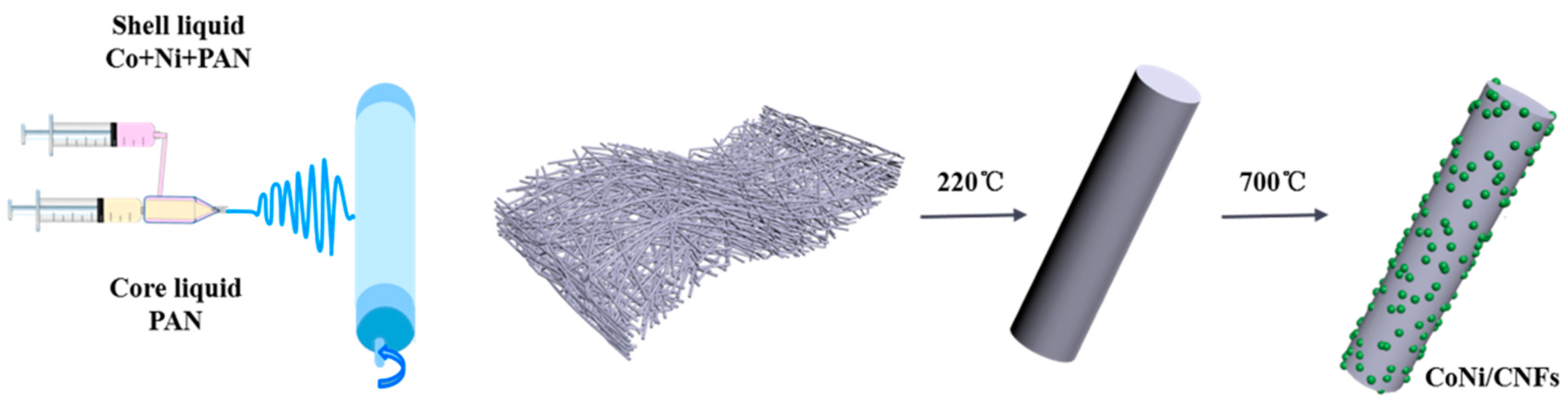
Flexible CoNi@CNF electrochemical catalysts were successfully synthesized by a coaxial electrostatic spinning technique, and the gradient distribution of the CoNi alloy on carbon fibers was achieved by changing the propulsion rate of the inner axis, which proved that the inner axis feeding speed is an effective method to regulate the distribution of the CoNi alloy on carbon fibers.
(2)
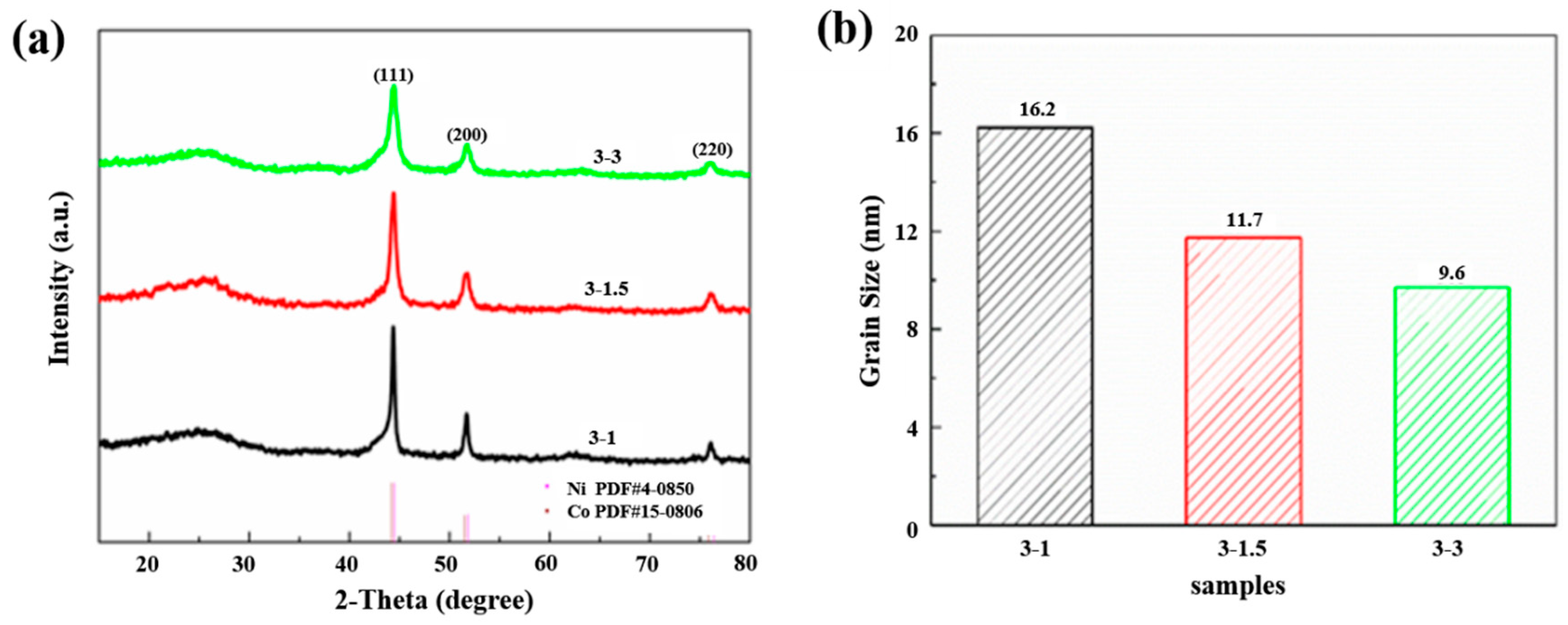
While keeping the feed speed (3 mm/h) of the outer axis (mixture of Co and Ni salts) constant, the CoNi alloy tended to be distributed on the carbon fiber toward the surface as the feed speed (1 mm/h, 1.5 mm/h, and 3 mm/h) of the inner axis (pure PAN solution) increased. When the internal axis feed speed was 1 mm/h, there was almost no distribution of CoNi alloy particles on the surface of the carbon fiber; when the internal axis feed speed was 1.5 mm/h, the CoNi alloy showed a semi-mosaic structure on the carbon fiber; when the internal axis feed speed was further increased to 3 mm/h, the CoNi alloy particles precipitated from the surface of the carbon fiber and the internal segregation phenomenon appeared, which was not conducive to the exposure of the active sites.
(3)
The 3-1.5 sample has the optimum oxygen reduction onset potential and half-slope potential of 0.99 V and 0.92 V (vs. RHE), respectively, with a diffusion limit current density of 6.31 mA/cm−2. The current strength retention rate is 95.2% after the 20,000 s timed current test. This outstanding performance is attributed to the abundance and small size of the CoNi alloy distributed on the exterior of the carbon fiber, which exposes more active material and facilitates charge transport, thus corresponding to a higher oxygen reduction efficiency.

Author Contributions

C.L.: writing—review and editing and resources. H.O.: theoretical guidance, project administration, supervision, and design conception. L.B.: writing—original draft. J.L.: data collation and formal analysis. R.G.: conceptualization and investigation. The manuscript was written with contributions from all authors. All authors have read and agreed to the published version of the manuscript.

Funding

This research was supported by the National Nature Science Foundation of China (Grant No. 5217130277), the Natural Science Foundation of Shaanxi Province (Grant No. 2021JZ-51), and the Foundation of Education Department of Shaanxi Province (Grant No. 20JC007).

Data Availability Statement

No new data were created or analyzed in this study. Data sharing is not applicable to this article.

Conflicts of Interest

The authors declare no conflict of interest.

References

  1. Dong, C.; Yang, L. Scalable Solid-Phase Synthesis of Defect-Rich Graphene for Oxygen Reduction Electrocatalysis. Green Energy Environ. 2023, 8, 224–232. [Google Scholar] [CrossRef]
  2. Zeng, Q.; Liu, D. Electronic and Lattice Strain Dual Tailoring for Boosting Pd Electrocatalysis in Oxygen Reduction Reaction. Iscience 2021, 24, 103332. [Google Scholar] [CrossRef]
  3. Laszczynska, A.; Tylus, W. Electrocatalytic Properties for The Hydrogen Evolution of The Electrodeposited Ni-Mo/WC Composites. Int. J. Hydrogen Energy 2021, 46, 22813–22831. [Google Scholar] [CrossRef]
  4. Shi, R.; Huang, Y. Synthesis of Ti4O7/Ti3O5 Dual-Phase Nanofibers with Coherent Interface for Oxygen Reduction Reaction Electrocatalysts. Materials 2020, 13, 3142. [Google Scholar] [CrossRef]
  5. Liu, M.; Chun, H. Tuning the Site-to-Site Interaction in Ru−M (M = Co, Fe, Ni) Diatomic Electrocatalysts to Climb up the Volcano Plot of Oxygen Electroreduction. ACS Nano 2022, 16, 10657–10666. [Google Scholar] [CrossRef]
  6. Shi, G.Y.; Hashimoto, T. Enhanced Oxygen reduction Electrocatalysis on PtCoSn Alloy Nanocatalyst Mediated by Ta-doped SnO2 Support for Polymer Electrolyte Fuel Cells. Electrochim. Acta 2021, 390, 138894. [Google Scholar] [CrossRef]
  7. Mahlia, T.M.I.; Syazmi, Z.A.H.S. Patent Landscape Review on Biodiesel Production: Technology Updates. Renew. Sustain. Energy Rev. 2020, 118, 109526. [Google Scholar] [CrossRef]
  8. Silitonga, A.S.; Shamsuddin, A.H. Biodiesel Synthesis from Ceiba Pentandra Oil by Microwave Irradiation-Assisted Transesterification: ELM Modeling and Optimization. Renew. Energy 2020, 146, 1278–1291. [Google Scholar] [CrossRef]
  9. Morozan, A.; Jousselme, B.; Palacin, S. Low-platinum and Platinum-free Catalysts for The Oxygen Reduction Reaction at Fuel Cell Cathodes. Energy Environ. Sci. 2011, 4, 1238–1254. [Google Scholar] [CrossRef]
  10. Li, W.D.; Liu, Y. Carbon-Quantum-Dots-loaded Ruthenium Nanoparticles as an Efficient Electrocatalyst for Hydrogen Production in Alkaline Media. Adv. Mater. 2018, 30, 1800676. [Google Scholar] [CrossRef]
  11. He, H.; Zhang, Y. Recent Innovations of Silk-derived Electrocatalysts for Hydrogen Evolution Reaction, Oxygen Evolution Reaction and Oxygen Reduction Reaction. Int. J. Hydrogen Energy 2021, 46, 7848–7865. [Google Scholar] [CrossRef]
  12. Cheng, F.; Su, Y. MnO2-based Nanostructures as Catalysts for Electrochemical Oxygen Reduction in Alkaline Media. Chem. Mater. 2010, 22, 898–905. [Google Scholar] [CrossRef]
  13. Johnson, D.; Pranada, E.; Yoo, R. Review and Perspective on Transition Metal Electrocatalysts Toward Carbon-neutral Energy. Energy Fuel 2023, 37, 1545–1576. [Google Scholar] [CrossRef]
  14. Ma, R.; Lin, G.; Zhou, Y. A Review of Oxygen Reduction Mechanisms for Metal-Free Carbon-Based Electrocatalysts. Comput. Mater. 2019, 5, 78. [Google Scholar] [CrossRef]
  15. Ma, M.; Yang, Z.C. Nickel Cobalt Phosphide with Three-Dimensional Nanostructure as a Highly Efficient Electrocatalyst for Hydrogen Evolution Reaction in both Acidic and Alkaline Electrolytes. Nano Res. 2019, 12, 375–380. [Google Scholar] [CrossRef]
  16. Majeed, A.; Li, X. Monolayer Carbon-Encapsulated Mo-doped Ni Nanoparticles Anchored on Single-Wall Carbon Nanotube Film for Total Water Splitting. Appl. Catal. B Environ. 2020, 269, 118823. [Google Scholar] [CrossRef]
  17. Zhang, X.Y.; Guo, B.Y. Ultrafine and Highly-Dispersed Bimetal Ni2P/Co2P Encapsulated by Hollow N-doped Carbon Nanospheres for Efficient Hydrogen Evolution. Int. J. Hydrogen Energy 2019, 44, 14908–14917. [Google Scholar] [CrossRef]
  18. Wang, J.; Ciucci, F. Boosting Bifunctional Oxygen Electrolysis for N-Doped Carbon via Bimetal Addition. Small 2017, 13, 1604103. [Google Scholar] [CrossRef]
  19. Wang, J.; Gao, Y. Bimetal-decorated Nanocarbon as a Superior Electrocatalyst for Overall Water Splitting. Power Sources 2018, 401, 312–321. [Google Scholar] [CrossRef]
  20. Eisenberg, D.; Stroek, W. A Simple Synthesis of an N-doped Carbon ORR Catalyst: Hierarchical Micro/Meso/Macro Porosity and Graphitic Shells. Chemistry 2016, 22, 501–505. [Google Scholar] [CrossRef]
  21. Alegre, C.; Modica, E. Bifunctional Oxygen Electrode Based on a Perovskite/Carbon Composite for Electrochemical Devices. Electroanal. Chem. 2018, 808, 412–419. [Google Scholar] [CrossRef]
  22. Gabe, A.; Ruiz-Rosas, R. Understanding of Oxygen Reduction Reaction by Examining Carbon-oxygen Gasification Reaction and Carbon Active Sites on Metal and Heteroatoms Free Carbon Materials of Different Porosities and Structures. Carbon 2019, 148, 430–440. [Google Scholar] [CrossRef]
  23. Ryabova, A.S.; Bonnefont, A. Further Insights into the Role of Carbon in Manganese Oxide/Carbon Composites in the Oxygen Reduction Reaction in Alkaline media. Electrochim. Acta 2017, 246, 643–653. [Google Scholar] [CrossRef]
  24. Quílez-Bermejo, J.; García-Dalí, S. Advanced Design of Metal Nanoclusters and Single Atoms Embedded in C1N1-Derived Carbon Materials for ORR, HER, and OER. Adv. Funct. Mater. 2023. [Google Scholar] [CrossRef]
  25. Fu, Y.; Yu, H.Y. NiCo Alloy Nanoparticles Decorated on N-Doped Carbon Nanofibers as Highly Active and Durable Oxygen Electrocatalyst. Adv. Funct. Mater. 2018, 28, 1705094. [Google Scholar] [CrossRef]
  26. Xue, J.J.; Wu, T. Electrospinning and Electrospun Nanofibers: Methods, Materials, and Applications. Chem. Rev. 2019, 119, 5298–5415. [Google Scholar] [CrossRef]
  27. Verma, S.; Sinha-Ray, S. Electrospun CNF Supported Ceramics as Electrochemical Catalysts for Water Splitting and Fuel Cell: A Review. Polymers 2020, 12, 238. [Google Scholar] [CrossRef]
  28. Su, H.; Wang, H. Enriching Co Nanoparticles inside Carbon Nanofibers via Nanoscale Assembly of Metal-organic Complexes for Highly Efficient Hydrogen Evolution. Nano Energy 2016, 22, 79–86. [Google Scholar] [CrossRef]
  29. Ma, Q.; Song, H. Iron-Nitrogen-Carbon Species Boosting Fast Conversion Kinetics of Fe1-xS@C Nanorods as High Rate Anodes for Lithium Ion Batteries. Chem. Eng. J. 2018, 338, 726–733. [Google Scholar] [CrossRef]
  30. Zhu, Q.L.; Xia, W. Metal-Organic Framework-Derived Honeycomb-Like Open Porous Nanostructures as Precious-Metal-Free Catalysts for Highly Efficient Oxygen Electro-reduction. Adv. Mater. 2016, 28, 6391–6398. [Google Scholar] [CrossRef]
  31. Li, T.F.; Li, S.L. Immobilization of Ni3Co Nanoparticles into N-doped Carbon Nanotube/Nanofiber Integrated Hierarchically Branched Architectures toward Efficient Overall Water splitting. Adv. Sci. 2020, 7, 1902371. [Google Scholar] [CrossRef]
  32. Li, M.; Wang, H.Y. RuNi Nanoparticles Embedded in N-doped Carbon Nanofibers as a Robust Bifunctional Catalyst for Efficient Overall Water Splitting. Adv. Sci. 2020, 7, 1901833. [Google Scholar] [CrossRef]
  33. Liu, Q.; Cao, S.B. Trimetallic FeCoNi-N/C nanofibers with High Electrocatalytic Activity for Oxygen Reduction Reaction in Sulfuric acid Solution. J. Electroanal. Chem. 2018, 813, 52–57. [Google Scholar] [CrossRef]
  34. Lei, Z.; Tan, Y. Defects Enriched Hollow Porous Co-N-doped Carbons Embedded with Ultrafine CoFe/Co Nanoparticles as Bifunctional Oxygen Electrocatalyst for Rechargeable Flexible Solid Zinc-air Batteries. Nano Res. 2021, 14, 868–878. [Google Scholar] [CrossRef]
  35. Chen, D.; Zhu, J. Nitrogen-Doped Carbon Coupled FeNi3 Intermetallic Compound as Advanced Bifunctional Electrocatalyst for OER, ORR and Zn-air Batteries. Appl. Catal. B Environ. 2020, 268, 118729. [Google Scholar] [CrossRef]
  36. Wang, J.; Kim, J. A Review of Carbon-Supported Nonprecious Metals as Energy-Related Electrocatalysts. Small Methods 2020, 4, 2000621. [Google Scholar] [CrossRef]
  37. Fei, H.L.; Dong, J.C. General Synthesis and Definitive Structural Identification of MN4C4 Single-atom Catalysts with Tunable Electrocatalytic Activities. Nat. Catal. 2018, 1, 63–72. [Google Scholar] [CrossRef]
  38. Li, Z.H.; He, H.Y. Atomic Co/Ni Dual Sites and Co/Ni Alloy Nanoparticles in N-doped Porous Janus-like Carbon Frameworks for Bifunctional Oxygen Electrocatalysis. Appl. Catal. B Environ. 2019, 240, 112–121. [Google Scholar] [CrossRef]
  39. Surendran, S.; Shanmugapriya, S. Electrospun Carbon Nanofibers Encapsulated with NiCoP: A Multifunctional Electrode for Supercapattery and Oxygen Reduction, Oxygen Evolution, and Hydrogen Evolution Reactions. Adv. Energy Mater. 2018, 8, 1800555. [Google Scholar] [CrossRef]
  40. Gu, H.H.; Fan, W. Phosphorus-doped NiCo2S4 Nanocrystals Grown on Electrospun Carbon Nanofibers as Ultra-efficient Electrocatalysts for the Hydrogen Evolution Reaction. Nanoscale Horiz. 2017, 2, 277–283. [Google Scholar] [CrossRef]
  41. Li, W.; Zhao, Y. Exploiting Ru-Induced Lattice Strain in CoRu Nanoalloys for Robust Bifunctional Hydrogen Production. Angew. Chem. Int. Ed. 2021, 60, 3290–3298. [Google Scholar] [CrossRef]
  42. Xia, C.; Qiu, Y. General Synthesis of Single-atom Catalysts with High Metal Loading Using Graphene Quantum Dots. Nat. Chem. 2021, 13, 887–894. [Google Scholar] [CrossRef]
  43. Miao, Q.; Yang, S. Constructing Synergistic Zn-N4 and Fe-N4O Dual-Sites from the COF@MOF Derived Hollow Carbon for Oxygen Reduction Reaction. Small Struct. 2022, 3, 2100225. [Google Scholar] [CrossRef]
  44. Darband, G.B.; Aliofkhazraei, M. Three-dimensional Ni-Co Alloy Hierarchical Nanostructure as Efficient Non-noble-metal Electrocatalyst for Hydrogen Evolution Reaction. Appl. Surf. Sci. 2019, 465, 846–862. [Google Scholar] [CrossRef]
  45. Chang, Z.D.; Lin, R.B. Construction of a Thiourea-based Metal-organic Framework with Open Ag+ Sites for the Separation of Propene/Propane Mixtures. Mater. Chem. A 2019, 7, 25567–25572. [Google Scholar] [CrossRef]
  46. Cheng, Q.Q.; Han, S.B. Co Nanoparticle Embedded in Atomically-dispersed Co-N-C Nanofibers for Oxygen Reduction with High Activity and Remarkable Durability. Nano Energy. 2018, 52, 485–493. [Google Scholar] [CrossRef]
  47. Li, M.X.; Zhu, Y. Ni Strongly Coupled with Mo2C Encapsulated in Nitrogen-Doped Carbon Nanofibers as Robust Bifunctional Catalyst for Overall Water Splitting. Adv. Energy Mater. 2019, 9, 1803185. [Google Scholar] [CrossRef]
  48. Tu, Y.C.; Ren, P.J. Structural and Electronic Optimization of Graphene Encapsulating Binary Metal for Highly Efficient Water Oxidation. Nano Energy 2018, 52, 494–500. [Google Scholar] [CrossRef]
  49. Dong, T.; Zhang, X. Hierarchical Nickel-cobalt Phosphide Hollow Spheres Embedded in P-doped Reduced Graphene Oxide Towards Superior Electrochemistry activity. Carbon 2019, 149, 222–233. [Google Scholar] [CrossRef]
  50. Gan, D.; Huang, Z. Graphene Oxide-Templated Conductive and Redox-Active Nanosheets Incorporated Hydrogels for Adhesive Bioelectronics. Adv. Funct. Mater. 2020, 30, 1907678. [Google Scholar] [CrossRef]
  51. Chen, G.B.; Wang, T. Accelerated Hydrogen Evolution Kinetics on NiFe-Layered Double Hydroxide Electrocatalysts by Tailoring Water Dissociation Active Sites. Adv. Mater. 2018, 30, 1706279. [Google Scholar] [CrossRef]
  52. Du, F.; Shi, L. Foam-like Co9S8/Ni3S2 Heterostructure Nanowire Arrays for Efficient Bifunctional Overall Water-splitting. Appl. Catal. B Environ. 2019, 253, 246–252. [Google Scholar] [CrossRef]
  53. Wang, Q.; Ye, K. Carbon Nanotube-Encapsulated Cobalt for Oxygen Reduction: Integration of Space Confinement and N-doping. Chem. Commun. 2019, 55, 14801–14804. [Google Scholar] [CrossRef]
  54. Huang, R.; Chen, W.X. Well-designed Cobalt-nickel Sulfide Microspheres with Unique Peapod-like Structure for Overall Water Splitting. Colloid. Interface Sci. 2019, 556, 401–410. [Google Scholar] [CrossRef]
  55. Yu, X.W.; Jun Zhao, J. Interfacial Engineering of Nickel Hydroxide on Cobalt Phosphide for Alkaline Water Electrocatalysis. Adv. Funct. Mater. 2021, 31, 2101578. [Google Scholar] [CrossRef]
  56. Suo, N.; Dou, Z.Y. Interface and Composition Engineering of Vanadium Doped Cobalt Nickel Sulfide/Phosphide Heterostructure for Efficient Water Splitting. Electrochimica Acta 2021, 368, 137602. [Google Scholar] [CrossRef]
  57. Li, C.; Mei, X.H. Hybridizing Amorphous Nickel Cobalt Phosphate and Nickel Phosphide as an Efficient Bifunctional Nanocatalyst Towards Overall Water Splitting. Catal. Today 2020, 358, 215–220. [Google Scholar] [CrossRef]
  58. Xie, Q.J.; Zheng, W.Z. Fe-Doping Induced Divergent Growth of Ni-Fe Alloy Nanoparticles for Enhancing the Electrocatalytic Oxygen reduction. Catal. Sci. Technol. 2021, 11, 5171–5179. [Google Scholar] [CrossRef]
  59. Fu, S.F.; Zhu, C.Z. Enhanced Electrocatalytic Activities of PtCuCoNi Three-Dimensional Nanoporous Quaternary Alloys for Oxygen Reduction and Methanol Oxidation Reactions. ACS Appl. Mater. Interfaces 2016, 8, 6110–6116. [Google Scholar] [CrossRef]
  60. Wang, P.; Zhao, Y. High Electrocatalytic Performance of Fe3C-encapsulated N-doped Carbon Nanotubes and Nanosheets for Oxygen Reduction Reaction. Mater. Res. Bull. 2022, 149, 111719. [Google Scholar] [CrossRef]
  61. Bouleau, L.; Pérez-Rodríguez, S.J. Quílez-Bermejo. Best Practices for ORR Performance Evaluation of Metal-free Porous Carbon Electrocatalysts. Carbon 2022, 189, 349–361. [Google Scholar] [CrossRef]
  62. Jiang, H.L.; Lin, Y.X. Ternary Interfacial Superstructure Enabling Extraordinary Hydrogen Evolution Electrocatalysis. Mater. Today 2018, 21, 602–610. [Google Scholar] [CrossRef]
  63. Wang, Z.; Jiang, Y.Q. Synthesis of Porous Fe3C-based Composite Beads as Heterogeneous Oxidation Catalysts. Chem. Eur. J. 2019, 25, 4175–4183. [Google Scholar] [CrossRef]
  64. Xiao, Z.; Hou, F. Confinement of Fe2O3 Nanoparticles in the Shell of N-doped Carbon Hollow Microsphere for Efficient Oxygen Reduction Reaction. Chem. Eng. Sci. 2019, 207, 235–246. [Google Scholar] [CrossRef]
Figure 1. Schematic illustration for the synthesis process of CoNi/CNFs.
Catalysts 13 00890 g001
Figure 2. (a) XRD patterns and (b) average crystallite size of the prepared CoNi/CNFs.
Catalysts 13 00890 g002
Figure 3. SEM and TEM images of the prepared CoNi/CNFs added with different feed speeds of the inner shaft: (a0a2) 1 mm/h: 3-1, (b0b2) 1.5 mmol: 3-1.5, and (c0c2) 3 mmol: 3-3.
Catalysts 13 00890 g003
Figure 4. (a) HADDF-STEM image and elemental mappings of Co, Ni, N, and S, (b,c) HRTEM images of sample. (purple arrows are CoNi alloy (111), bule arrows are Graphitic layers (002), orange arrow is CoNi alloy (200)).
Catalysts 13 00890 g004
Figure 5. (a) Raman patterns and (b) graphitization degree of the prepared CoNi/CNFs with different feed speeds of the inner shaft. (black curves represent the original data. blue curves represent the automatically generated green curves represent D band of C atom crystal characteristic, red curves represent G band of C atom crystal characteristic).
Catalysts 13 00890 g005
Figure 6. High-resolution XPS spectra of CoNi/CNFs with different feed speeds of the inner shaft: (a,b) 3-1: Co2p, Ni2p; (c,d) 3-1.5: Co2p, Ni2p; (e,f) 3-3: Co2p, Ni2; (g) 3-1, 3-1.5, 3-3: C1s, (black curves represent the original data. yellow curves represent the automatically generated. blue curves represent C-N, red curves represent C-C, purple curves represent C=O.) (h) 3-1, 3-1.5, 3-3: N1s. (black curves represent the original data. pink curves represent the automatically generated. green curves represent pyridine nitrogen, red curves represent graphite nitrogen.).
Catalysts 13 00890 g006aCatalysts 13 00890 g006b
Figure 7. Comparison of ORR performances of CoNi/CNF electrodes and commercial Pt/C catalyst: (a) LSV patterns of the prepared CoNi/CNFs with different feed speeds of the inner shaft and Pt/C, (b) n and H2O2 % patterns of the prepared CoNi/CNFs with different feed speeds of the inner shaft and Pt/C, (c) LSV curves collected under different rotation speeds and K-L plots for the 3-1.5 sample, (d) the comparison of methanol resistance of 3-1.5 samples and Pt/C, (e) the comparison of the stability of 3-1 sample and Pt/C, and (f) LSV curve after 5000 CV cycles of 3-1 sample.
Catalysts 13 00890 g007
Figure 8. Comparison of the prepared CoNi/CNFs with different propulsion rate of the inner shaft: (a) Cdl and (b) EIS.
Catalysts 13 00890 g008
Disclaimer/Publisher’s Note: The statements, opinions and data contained in all publications are solely those of the individual author(s) and contributor(s) and not of MDPI and/or the editor(s). MDPI and/or the editor(s) disclaim responsibility for any injury to people or property resulting from any ideas, methods, instructions or products referred to in the content.

