Article

Effect of the Microstructure of Composite CoMoS/Carbon Catalysts on Hydrotreatment Performances

1
IFP Energies Nouvelles, Rond-Point de l’échangeuvr de Solaize, BP 3, 69360 Solaize, France
2
ICGM, University Montpellier, CNRS, ENSCM, 34090 Montpellier, France
3
Institut de Chimie des Milieux et Matériaux de Poitiers (IC2MP), Université de Poitiers, UMR 7285 CNRS, 4 Rue Michel Brunet, TSA 71106, 86073 Poitiers, France
*
Authors to whom correspondence should be addressed.
Catalysts 2023, 13(5), 862; https://doi.org/10.3390/catal13050862
Submission received: 10 April 2023 / Revised: 28 April 2023 / Accepted: 4 May 2023 / Published: 9 May 2023
(This article belongs to the Section Catalytic Materials)

Abstract

:
Several CoMoS/carbons were successfully synthetized using hydrothermal-type approaches and a subsequent surface reaction for the promotion step with Co. The effect of the microstructure of carbons used as a matrix for CoMoS-based catalysts was studied in the case of hydrotreating reactions. It was found that 1D (nanofibers/tubes) or 2D (nanosheets) carbon nanostructures may influence the characteristics of the CoMoS crystallites (dispersion, promotion rate and orientation of the slabs) and as a consequence the catalytic properties. In particular, the HDS mechanism of the substituted 4-MethylDiBenzoThiophene (4-MDBT) was found to be microstructure-dependent, as well as the selectivity of 3-MethylThiophene (3-MT) HDS/2,3-DiMethylBut-2-eNe (2,3-DM2BN) hydrogenation.

1. Introduction

The topic of hydrodesulfurization (HDS) has been studied for many years, leading to an impressive compilation of knowledge establishing many structure–reactivity relationships. In particular, the origin of the selectivity of the direct desulfurization versus the hydrogenation route for various sulfur compounds contained in heavy petroleum cuts has been extensively investigated. It is now accepted that several parameters of the catalysts are likely to drive this selectivity, such as the morphology of the transition metal sulfide particles (length and stacking) [1], the metal support interaction or the promotion level [2,3,4,5,6,7,8].
The field of selective hydrodesulfurization of fluid catalytic cracking (FCC) gasoline has also stimulated comprehensive studies in order to control the selectivity between hydrodesulfurization and olefin hydrogenation reactions, and again the morphology and shape of the transition metal sulfide (TMS) crystallites were found to be key factors [9,10]. The ratio of corner to edge atoms [11] and slab length [12] are often reported as critical features governing the catalytic properties. The support is of course an important parameter to take into account, but most of the time its influence is discussed in terms of surface science since its acido-basic properties may modify the electronic properties of the supported active phase [13]. Nevertheless, the influence of the nanostructure of the carrier with different dimensions (fibers/nanotube and 2D lamellar) on the catalytic properties of the supported HDS catalysts has not been deeply studied in the literature or compared in the same catalytic conditions. This is likely due to the difficulty of controlling this parameter in the case of oxide carriers such as alumina, which is the most commonly used support in the field of hydrotreatment. In the case of carbon base supports, different research groups studied fibers [14], nanotubes [15] or graphene [16], showing interesting results in catalytic hydrotreatment.
In this work, we compared the catalytic performances of CoMoS composite catalysts prepared using carbon supports with different nanostructures, such as 1D (nanofibers/tubes) or 2D (nanosheets). Two different catalytic reactions have been used: HDS of 4-MDBT and hydrotreating of a mixture of 3-MT and 2,3-DM2BN.

2. Results and Discussion

2.1. Elemental Analysis

The elemental compositions of the supported CoMoS/carbons catalysts (before catalytic test) are summarized in Table 1. The metal loadings measured by XRF are consistent with the targeted values with a Co/Mo ratio of circa 0.4, close to the usually admitted optimum considered for HDS applications. Except for CoMoS/CNF-ox, the S over Mo molar ratio shows a little sub-stoichiometry compared to the theoretical value (2), suggesting the incomplete sulfidation of Mo (confirmed by XPS results presented hereafter, Table 2). Moreover, nitrogen contents in the PANI- and g-C3N4-based catalysts are slightly higher in agreement with the nature of the carbonaceous precursors used for these syntheses, the other N contribution coming from the sulfiding agent used for all the samples (thiourea).

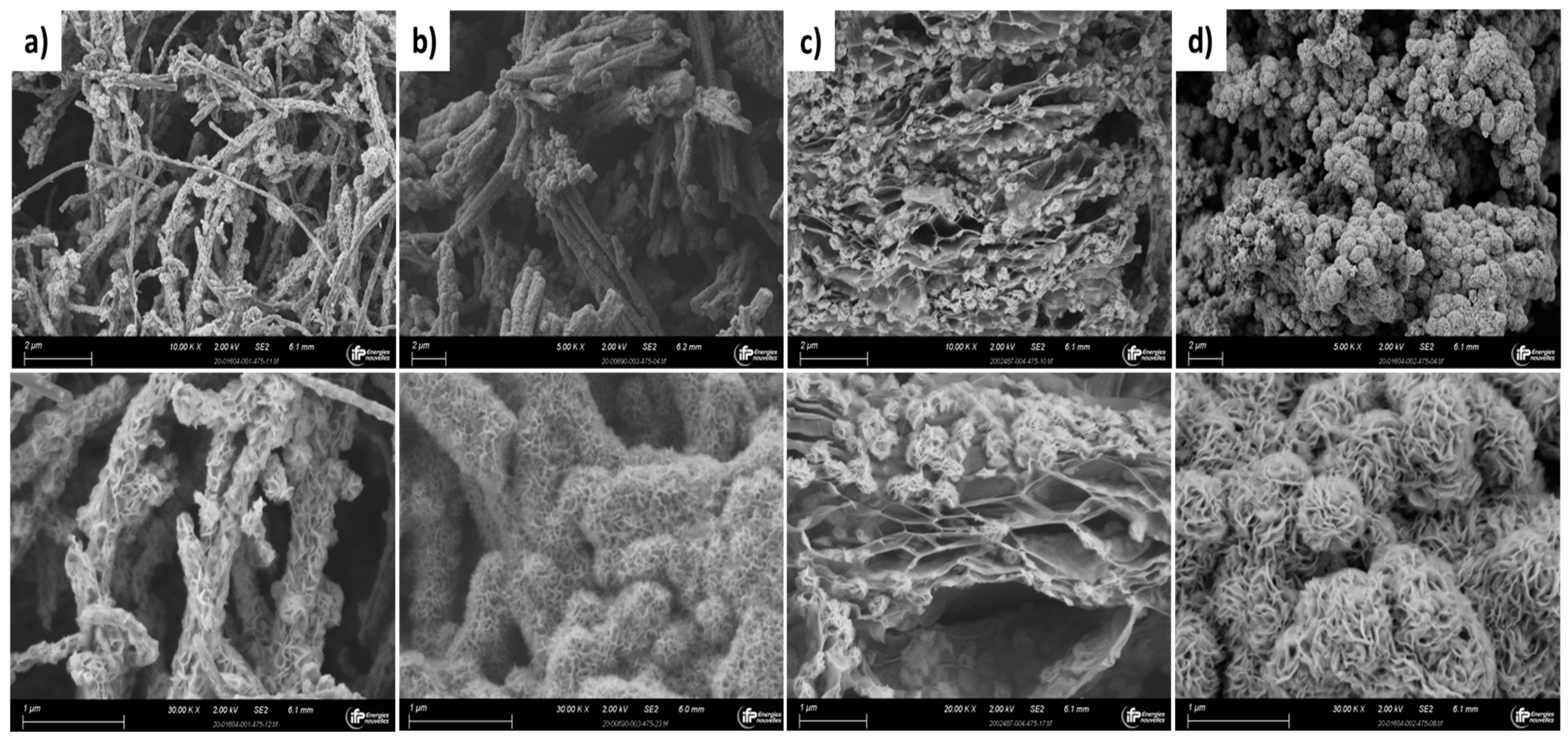
2.2. Textural Characterization and SEM Observations

The textural properties (SBET and Vp from Hg porosimetry) of the supported catalysts are reported in Table 1. One can notice the lower specific surface area of the CoMoS/r-GO, which is circa half that of the other solids. The porous volume of the CoMoS/CNF-ox and CoMoS/r-GO are 20–30% higher than their counterparts, with pore size distribution ranging from 0.2 to 10 µm for all the samples.
SEM observations performed on the fresh catalysts clearly show the different types of CoMoS/carbon mesostructures: 1D (wire or tubular) for CoMoS/CNF-ox and CoMoS/PANI, 2D for CoMoS/r-GO with spheroidal intercalated agglomerates and mainly 3D agglomerates for CoMoS/g-C3N4 (Figure 1). In the case of 1D morphologies, individual wires coated with CoMoS have similar dimensions (5–10 µm length and 0.2 µm width for CoMoS/CNF-ox, 10–20 µm length for 1 µm width for CoMoS/PANI), but fibers are more aggregated in the case of the PANI-based structure. For the other solids, CoMoS agglomerates exhibit a spheroidal shape (also called “urchin like”), mostly composed of isolated spheres with a mean diameter of 0.2 µm for CoMoS/r-GO and of larger agglomerated (0.6 µm) spheres for CoMoS/g-C3N4.

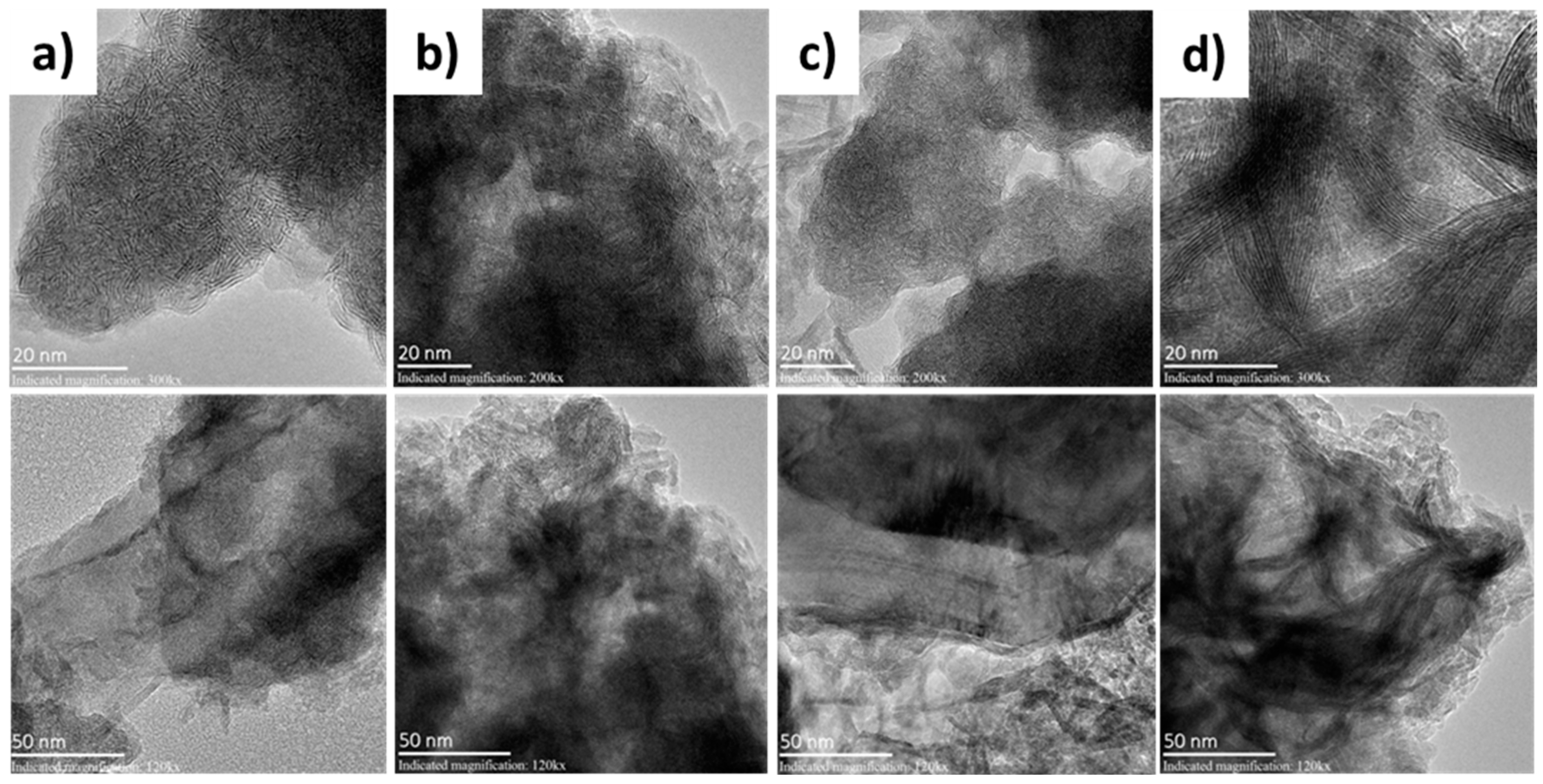
2.3. HR-TEM Characterisation

HR-TEM performed on the spent catalysts (after the catalytic tests) allows us to distinguish the characteristic 2D lamellar structures of CoMoS slabs, but due to their highly aggregated state an accurate determination of the mean slab length and stacking is not possible (Figure 2). The approximative ranges of slab lengths were visually estimated to be, respectively, 2–15 nm for CoMoS@CNF-ox and CoMoS@r-GO and 2–20 nm for CoMoS@PANI. The CoMoS/g-C3N4 sample contains much longer and highly stacked slabs, up to circa 50 nm length, thus suffering from a lower dispersion (ratio between active Mo edges + corner sites and total Mo atoms) of MoS2 slabs.

2.4. XPS Characterisation

The decomposition of the S 2p, Mo 3d and Co 2p XPS spectra was performed using the corresponding oxide and sulfided references as supported monometallic catalysts, and the decomposition methodology spectra are described in the Supplementary Materials. The case of CoMoS/PANI is given as an example (Figure S1). The relative compositions are tabulated in Table 2. According to the XPS results performed on the spent catalysts, all the solids have the same sulfidation rate considering the accuracy (between 73 and 85% of Mo atoms are in the MoS2 phase). Concerning the amounts of Co in the mixed phase (defined by %atCo.%CoMoS), CoMoS/CNF-ox and CoMoS/r-GO show the highest values (0.56 and 0.26, respectively), whereas in the case of CoMoS/PANI and CoMoS/g-C3N4 a large proportion of the Co introduced is segregated as a CoSx (50%) or Co2+ oxidic form (36%). Since the promotion step is realized by the deposition of Co(acac)2 on the preformed MoS/carbon samples, we can assess the influence of the initial structure of the unpromoted solids on the efficiency of this subsequent surface reaction. The denser structures of PANI- and C3N4-based catalysts as observed by HR-TEM probably hinder the accessibility of the Co precursor to Mo edge atoms to create mixed sites. Another option to explain the lower interaction of Co(acac)2 with the MoS2 surface is the presence of polar groups on the surface of the carbons created by the presence of nitrogen atoms on these two solids, causing a competitive adsorption of the Co precursor between the carbon carrier and the “MoS” sites.

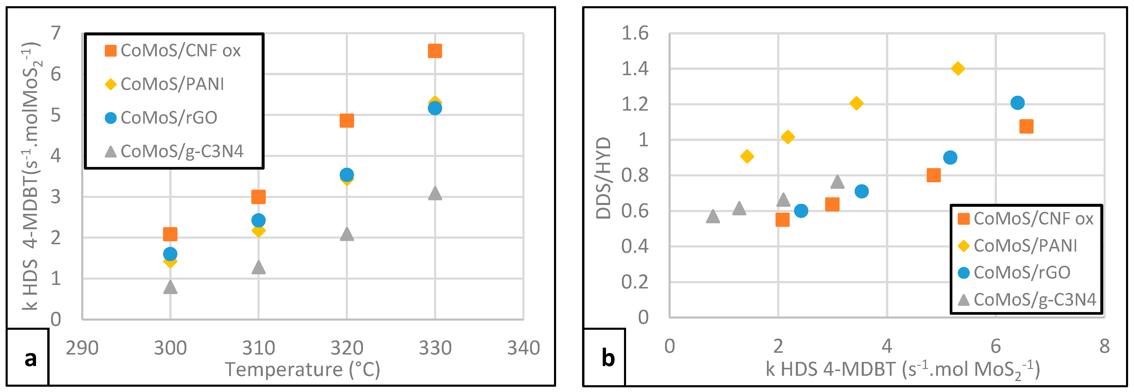
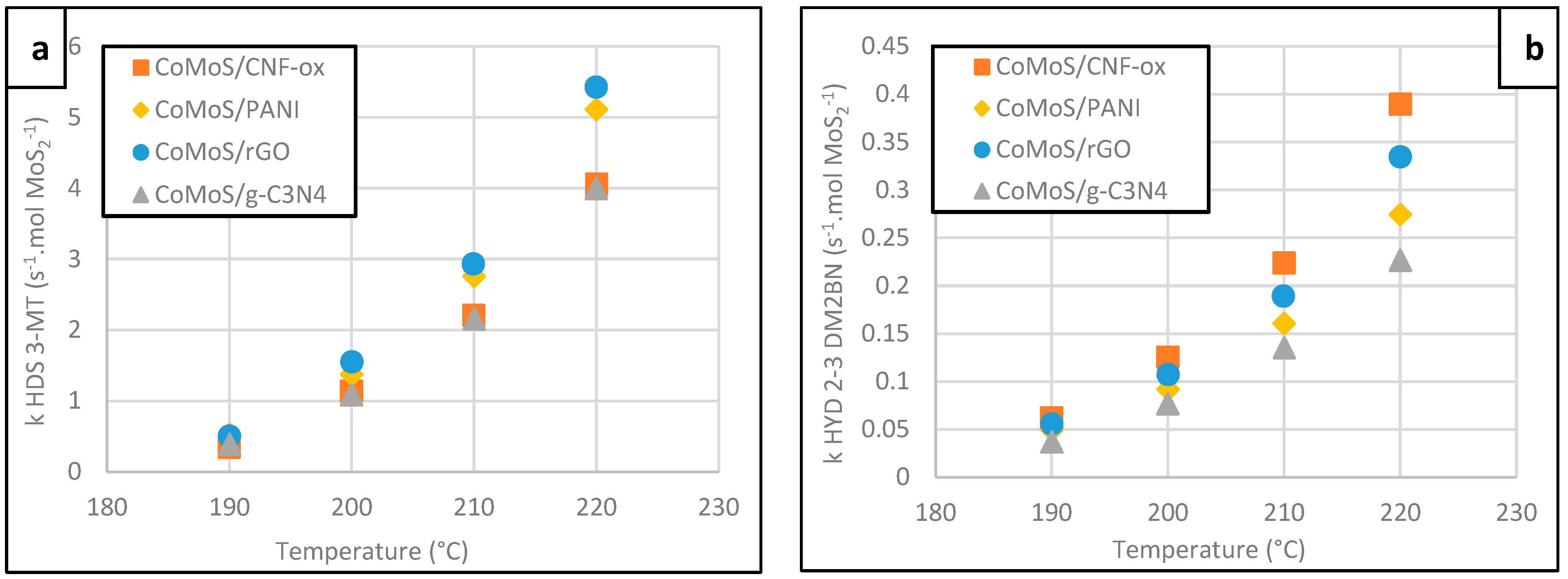
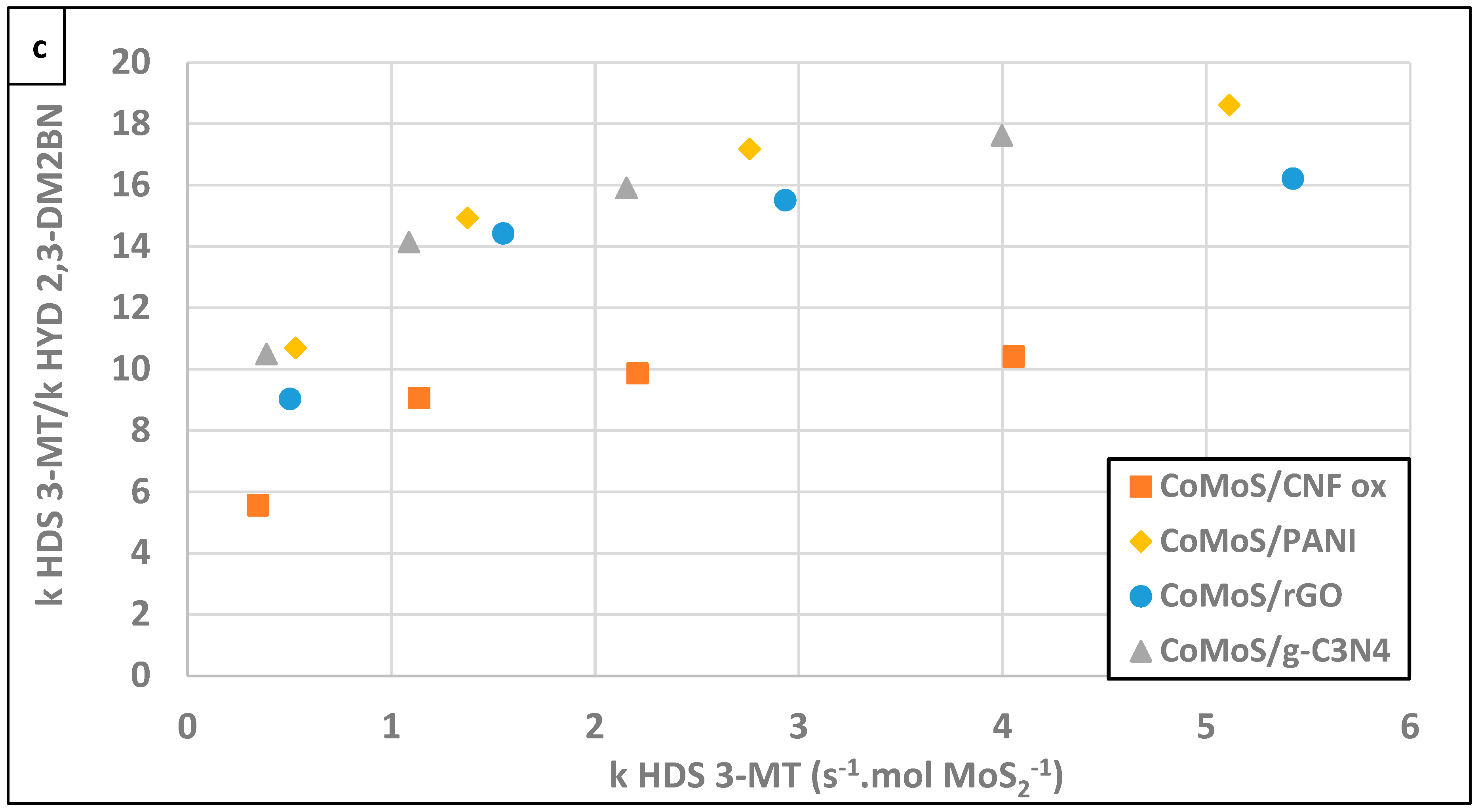
2.5. Catalytic Tests

Figure 3a,b present the 4-DMBT HDS performances of the different solids. The ranking is kCoMoS/CNF-ox > kCoMoS/r-GO ≈ kCoMoS/PANI > kCoMoS/g-C3N4. The higher activity of the CNF-ox-based catalyst may be due to its higher dispersion (as observed by HR-TEM) and Co promotion (% Co in the mixed phase) compared to the other catalysts. Conversely, due to the presence of very large slabs coupled with its low promotion rate, CoMoS/g-C3N4 exhibits the lowest activity. If we consider now the DDS/HYD selectivity ratio representative of the two possible pathways of the mechanism (Figure 4), we can observe that a significantly higher ratio is obtained for the CoMoS/PANI sample, whereas the other catalysts follow the same trend (Figure 3b). Interestingly, the DDS/HYD ratio for CoMoS/PANI is higher than 1 above 310 °C, which means that the transformation via the DDS route is favored compared to the HYD. Several CoMo-type catalysts supported on alumina tested in the same operating conditions gave DDS/HYD ratios ranging between 1.2 and 1.5, whereas for the more hydrogenating NiMo-type catalysts values lower than 1 are usually obtained. In other words, CoMo/Al2O3 catalysts usually promote the DDS route of the 4-MDBT hydrodesulfurization; instead, in the case of NiMo/Al2O3, the HYD pathway is preferred [17]. In our case, one can say that CoMoS/PANI promotes the DDS route as usually observed for the CoMoS phase, whereas the other composite catalysts favor the HYD route. Hence, the DDS pathway is not an intrinsic signature of the CoMoS phase. Moreover, for all the catalysts, the increase in the HDS reaction rate is due to the increase in the DDS contribution, since the DDS/HYD ratio increases with T (and HDS). This evolution is in agreement with the literature since usually the activation energy for DDS is higher than for the HYD route [18].
It is well documented that the presence of alkyl groups on DBT molecule strongly decreases their reactivity due to steric hindrance, which inhibits the direct perpendicular bonding of the S to the coordinatively unsaturated sites (CUS) of the catalyst [19,20,21]. As a consequence, the reaction pathway will go mainly through the hydrogenation route, with a flat adsorption of the aromatic ring of the sulfur-containing molecule in particular when the alkyl group is the 4 or 6 (or both) position. Considering this, one can assume that the CoMoS/PANI composite favors the direct perpendicular adsorption mode of the S atom on the CUS. This effect may be due to a favorable vertical orientation of the slabs for such adsorption mode in relation to the formation process of the sulfide phase with a sulfidation step for the embedded MoOx/PANI crystallites instead of sulfiding the molecular precursors in solution for the other samples [15]. For these last composites, the flat adsorption of the aromatic route seems to be preferred since the HYD route prevails. This interesting result shows that the adsorption mode may be tuned for a given transition metal sulfide phase in order to obtain a better control of the mechanism.
Figure 4. 4-MDBT hydrodesulfurization pathways via DDS or HYD route [22].
Catalysts 13 00862 g004
Figure 5a–c present the results of the catalytic tests performed on the 3-MT/2-3 DM2BN mixture. The 3-MT HDS activity of the CoMoS/PANI and CoMoS/rGO are slightly higher compared to g-C3N4- and CNF-ox-based composites (Figure 5a). The lowest activities for both 3-MT HDS (Figure 5a) and 2-3 DM2BN HYD (Figure 5b) molecules were observed for the CoMoS/g-C3N4. Again, we may invoke its poor Co promotion rate and large/stacked slabs to explain this last result. In the case of the CoMoS/CNF-ox, 3-MT hydrodesulfurization is likely limited by the competitive olefin hydrogenation reaction since this catalyst is quite active for that reaction too, with in turn a poor kHDS/kHYD selectivity compared to its counterparts (Figure 5c).

3. Materials and Methods

3.1. Synthesis of MoS2/Carbon Composites

Ammonium heptamolybdate (AHM, (NH4)6Mo7O24·4H2O), thioacetamide (CH3CSNH2), cobalt acetylacetonate (Co(acac)2·2H2O), carbon nanofibers (CNFs, graphitized iron-free composed of conical platelets, D × L 100 nm × 20–200 μm), hydrogen peroxide aqueous solution (H2O2, 30% (w/w) in water), potassium permanganate (KMnO4), graphite powder (<20 µm) and cetyltrimethylammonium bromide (CTAB; CH3(CH2)15N(Br)(CH3)3) were purchased from Aldrich. Sodium molybdate (Na2MoO4·2H2O), urea (NH2CONH2) and thiourea (NH2CSNH2) were obtained from Alfa Aesar. Concentrated nitric acid (65 wt%, HNO3), concentrated hydrochloric acid (37 wt%, HCl) and concentrated sulfuric acid (95–97 wt%, H2SO4) were obtained from Merck. γ-Alumina (SBET = 265 m2/g) was obtained from Axens. All the syntheses were carried out in deionized water obtained from a Millipore system (σ ~0.1 µS/cm).

3.1.1. Synthesis of MoS2/PANI

Polyaniline (PANI)-supported MoS2 was synthesized following the reported literature with slight modifications [23]. The starting material, molybdenum oxide supported on PANI (MoOx/PANI), was synthesized following our recent report [24]. In a typical hydrothermal synthesis, 2 g of as-prepared MoOx/PANI (SBET = 8 m2/g, 38.7 wt% Mo) was dispersed in 100 mL of deionized water via ultrasonication for 1 h at 30 °C and 1.5 g thiourea (corresponding to a S/Mo molar ratio of 2.1) was added subsequently. The homogenous suspension was transferred into a Teflon-lined stainless-steel autoclave and reacted under argon at 190 °C for 48 h. The reaction mixture was naturally cooled down and the black precipitate was centrifugated for 3 min at 5000 rpm using a Hettick Rotofix 32A centrifuge, isolated and washed with deionized water four times and with ethanol one time. The resulting black powder was dried at 50 °C in a vacuum oven (p = 50 mbar) for 6 h and the powder was transferred in an argon-filled glove box.

3.1.2. Synthesis of MoS2/CNF-ox

At first, CNFs were oxidized in order to enhance surface hydrophilicity, following the procedure reported in the literature [25]. Shortly, 8 g of CNFs was introduced in 80 mL of acid mixture (1:1 vol./vol. ratio with 40 mL HNO3 and 40 mL H2SO4) and heated at reflux for 1 h under stirring and air. After cooling down the reaction mixture, the solution was diluted with deionized water and the suspension was filtered at room temperature over a Teflon membrane filter (pore diameter of 0.2 μm) and washed with water until the filtrate became neutral. The obtained powder was dried under air at 120 °C for 16 h. In order to synthesize CNFs-supported MoS2, 0.44 g of oxidized CNFs, 2 g of thiourea and 1.92 g of AHM (corresponding to a S/Mo molar ratio of 2.4) were dispersed in 300 mL of deionized water for 1 h under ultrasonication. The suspension was transferred in a Teflon-lined stainless-steel autoclave and reacted under argon at 180 °C for 24 h. After cooling down, the black precipitate was centrifugated for 3 min at 5000 rpm using a Hettick Rotofix 32A centrifuge, isolated and washed with deionized water four times and with ethanol one time. The powder was dried in a vacuum oven (p = 50 mbar) at 50 °C for 6 h and transferred and stored in an argon-filled glovebox.

3.1.3. Synthesis of MoS2/g-C3N4

Graphitized carbon nitride (g-C3N4) was synthesized following the procedure previously reported in the literature [26]. In a typical synthesis, 10 g of urea was heated up to 550 °C with a ramp rate of 5 °C/min and calcined at that temperature for 2 h under air and cooled down naturally. In case of synthesis of g-C3N4-supported MoS2, 1 g of as-prepared g-C3N4 (SBET = 12 m2/g), 3.03 g of Na2MoO4·2H2O and 0.36 g of CTAB were dispersed in 250 mL of deionized water for 1 h under ultrasonication at 30 °C. Following the addition of 1.88 g of CH3CSNH2 to the reaction mixture (corresponding to a S/Mo molar ratio of 2.0), the suspension was transferred in a Teflon-lined stainless-steel autoclave and reacted under argon at 180 °C for 30 h. After cooling down, the solid product was filtered and washed thoroughly with water and the powder was dried at 50 °C for 6 h in a vacuum oven (p = 50 mbar).

3.1.4. Synthesis of MoS2/r-GO

Graphite powder was oxidized following the previously reported procedure [27] and the oxidized sample was abbreviated as graphene oxide (GO). The synthesis and growth steps of in-situ-formed molybdenum disulfide (MoS2) and the reduction step of GO to r-GO were carried out in a single step method under hydrothermal conditions. The synthesis method for obtaining the r-GO-supported MoS2 was adapted from a previously published report [28]. Amounts of 1.24 g of AHM and 0.35 g of GO were dispersed in 175 mL of deionized water via ultrasonication at around 30 °C for 1 h. Subsequently, 2.28 g of thiourea (corresponding to a S/Mo molar ratio of 4.3) was added to the suspension and transferred into a Teflon-lined stainless-steel autoclave. The reaction mixture was reacted under argon at 180 °C for 24 h and after that naturally cooled down to room temperature. The solid product was isolated via centrifugation and washed thoroughly with water and ethanol. The final powder was dried at 50 °C for 6 h in a vacuum oven (p = 50 mbar).

3.1.5. Promotion of MoS2/Carbon by Co

The promotion of MoS2/carbon composites with Co(acac)2·2H2O was carried out at room temperature following the protocol developed by Bezverkhyy et al. [29]. In a typical experiment, required amount of Co(acac)2 (targeted Co to Mo molar ratio ~ 0.4) was dissolved in degassed methanol and then the catalyst was added to the reaction mixture and the suspension was stirred at 30 °C for 18 h under argon atmosphere. Methanol was evaporated by heating at 65 °C for 4 h. The residual solids were further dried under vacuum at 50 °C for 6 h.
A general scheme of the synthesis is given in Figure S2.

3.2. Characterization Methods

All samples were characterized by powder X-ray Fluorescence (XRF), CHNS elemental analysis, X-ray Photoelectron Spectroscopy (XPS), Hg porosimetry and electronic microscopy (SEM and HR-TEM). The methodology applied for XPS and HR-TEM analyses is available in the Supplementary Materials.

3.3. Catalytic Tests

Before catalytic tests, all the carbon-supported CoMoS composites were diluted with high-surface-area γ-Al2O3 (SBET = 265 m2g−1) used as binder. The γ-Al2O3 extrudates were grinded using a ball mill, the powder was sieved and the fraction below 64 μm was collected for better mixing with the catalyst. The Al2O3 powder was mixed with the catalyst in order to achieve 10 wt% equivalent MoO3 loading in the final solid (catalyst + γ-Al2O3) and the mixture was further ball-milled (3 min, 25 Hz). Afterwards, the powder was pelletized and sieved to collect the 0.355–1.25 mm fraction. This fraction was used for the catalytic tests.

3.3.1. HDS of 3-Methylthiophene (3-MT) in Presence of 2,3-Dimethylbut-2-ene (2,3-DM2BN)

HDS test of 3-methylthiophene (3-MT) in mixture with 2,3-dimethylbut-2-ene (2,3-DM2BN) (model FCC gasoline feedstock: 0.3 wt% 3-MT, 10 wt% 2,3-DM2BN dissolved in n-heptane 89.7 wt%) was carried out in a Flowrence Avantium unit. Each fixed bed reactor was loaded with 0.3 mL of catalyst. The catalyst activation was carried out using DMDS (4 wt%) in n-heptane (96 wt%) at a liquid hourly space velocity (LHSV) of 3 h−1 and a total pressure of 15 bars, raising the temperature from room temperature to 350 °C (2 °C/min) with a plateau of 2 h and a hydrogen-to-hydrocarbon (H2/HC) ratio of 300 NL/L. After this sulfidation step, the temperature was decreased from 350 °C to 190 °C and the catalysts were tested at four different temperatures (190, 200, 210 and 220 °C). LHSV was kept at 6 h−1, total pressure at 15 bars with H2/HC of 300 NL/L. The effluent mixture was analyzed by gas chromatography using a DB1 column and a flame ionization detector. Apparent first-order rate constant (k, s−1mole MoS2−1) was evaluated using the following expression (1):
k H D S   o r   H Y D = L H S V m o l e   M o S 2 × ln 1 1 x H D S   o r   H Y D
where x is the HDS conversion of 3-MT or hydrogenation (HYD) of 2,3-DM2BN. Normalization by m o l e   M o S 2   loaded in the reactor was performed using XRF values.

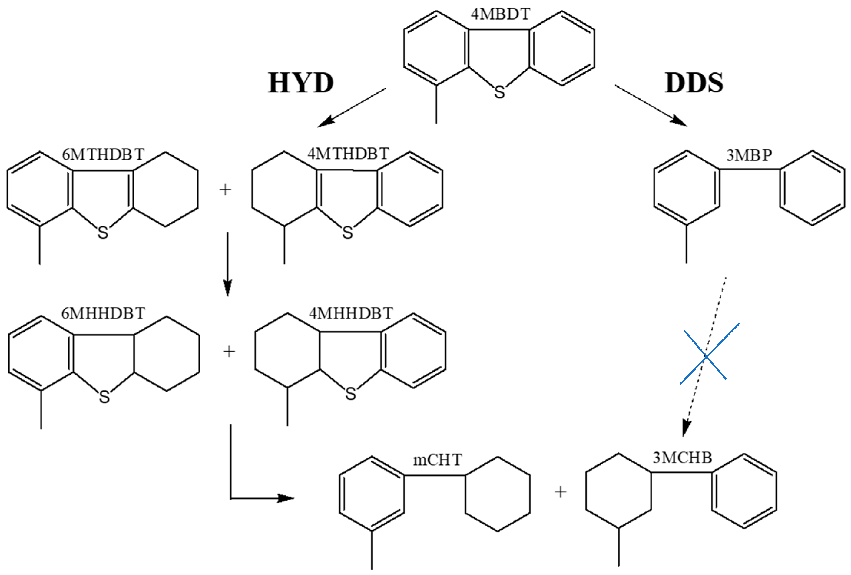
3.3.2. Hydrodesulfurization (HDS) of 4-Methyldibenzothiophene (4-MDBT)

HDS test of 4-methyldibenzothiophene (4-MDBT) was carried out in a Microcat fixed-bed unit. Each fixed-bed reactor was loaded with 0.75 mL of catalyst. The catalyst activation was carried out using DMDS (3 wt%) in ortho-xylene (97 wt%) at an LHSV of 25.6 h−1 and a total pressure of 30 bar, raising the temperature from room temperature to 350 °C (2 °C/min) with a plateau of 2 h and H2/HC ratio of 240 NL/L. After this sulfidation step, a feed consisting of 1.0 wt% 4-MDBT, 1.2 wt% DMDS, 96.8 wt% orthoxylene and 1.0 wt% dodecane (as internal standard) was injected. The catalysts were tested at four different temperatures ranging between 300 °C and 330 °C. LHSV was maintained at 11.1 h−1, total pressure at 30 bars and H2/HC at 240 NL/L. The effluents were analyzed by gas chromatography using a PIONA column and an FID detector. Apparent first-order rate constant ( k H D S   4 - M D B T , s−1mole MoS2−1) and DDS/HYD ratio were obtained using the following expressions (2) and (3):
k H D S   4 - M D B T = L H S V m o l e   M o S 2 × ln 1 1 x H D S   4 M D B T
D D S H Y D = s e l   3 - M B P s e l M C H T + 3 - M C H B
where 3-MBP: 3-methylbiphenyle, MCHT: methyl—cyclohexyltoluene, 3-MCHB: 3-methylcyclohexylbenzene. Normalization by m o l e   M o S 2   loaded in the reactor was performed using XRF.
It is well accepted that the 4-MDBT HDS mechanism may follow the direct desulfurization (DDS) or the hydrogenation (HYD) pathways as presented in Figure 4. We checked that in our experimental conditions the hydrogenation of the 3-MBP into 3-MCHB or MCHT was negligeable by performing a test using 3-MBP as reactant.

4. Conclusions

In this work, we successfully synthetized different CoMoS/carbon composites using hydrothermal-type approaches and a subsequent surface reaction for the promotion step by Co. We investigated the effect of these carbon nanostructures used as CoMoS crystallite carriers on the catalytic performances of two different hydrotreating reactions: hydrodesulfurization and hydrogenation of 4-MethylDiBenzoThiophene and a mixture of 3-MethylThiophene/2-3DimethylBut-2-ene. It was observed that 1D (nanofibers/tubes) or 2D sheet carbon nanostructures may influence the characteristics of the CoMoS crystallites (dispersion, promotion rate and orientation) and as a consequence the catalytic properties of the CoMoS@carbon composites. In particular, the HDS mechanism of the substituted 4-MDBT was found to be microstructure-dependent as well as the selectivity of 3-MethylThiophene HDS/2,3-DM2BN hydrogenation.

Supplementary Materials

The following supporting information can be downloaded at https://www.mdpi.com/article/10.3390/catal13050862/s1, Figure S1: XPS spectral decompositions (a) Mo 3d and (b) Co 2p (2p3/2 region of the spectrum) core level spectrum of spent sulfided CoMo/PANI catalyst chosen as an example. Figure S2: General scheme of the synthesis. References [30,31] are cited in the supplementary materials.

Author Contributions

S.G.: investigation, methodology, review and editing; A.P., P.L.-D., S.B. and L.C.: validation, review and editing; E.G.: validation, methodology, investigation, writing, review and editing, supervision; D.U.: conceptualization, investigation, writing, review and editing, supervision. All authors have read and agreed to the published version of the manuscript.

Funding

This research was funded by Agence Nationale de la Recherche grant number ANR PASSCATA—ANR-16-CE07-0029).

Data Availability Statement

Not applicable.

Acknowledgments

The authors thank the Agence Nationale de la Recherche (ANR) for the research project grant (ANR PASSCATA—ANR-16-CE07-0029), https://anr.fr/Project-ANR-16-CE07-0029 (accessed on 26 February 2023). The authors warmly thank Virgile Rouchon and Veronique Lefebvre for the microscopy observations, Saloua Sahal, Laurent Lemaitre and Christèle Legens for XPS characterizations and Denis Barrallon for the 4-MDBT catalytic tests.

Conflicts of Interest

The authors declare no conflict of interest.

References

  1. Daage, M.; Chianelli, R.R. Structure-Function Relations in Molybdenum Sulfide Catalysts: The “Rim-Edge” Model. J. Catal. 1994, 149, 414–427. [Google Scholar] [CrossRef]
  2. Candia, R.; Sørensen, O.; Villadsen, J.; Topsøe, N.Y.; Clausen, B.S.; Topsøe, H. Effect of sulfiding temperature on activity and structures of Co-Mo Al2O3 catalysts. 2. Bull. Sociétés Chim. Belg. 1984, 93, 783–806. [Google Scholar] [CrossRef]
  3. Tops⊘e, H.; Clausen, B.S. Importance of Co-Mo-S type structures in hydrodesulfurization. Rev.-Sci. Eng. 1984, 26, 395–420. [Google Scholar] [CrossRef]
  4. Stanislaus, A.; Marafi, A.; Rana, M.S. Recent advances in the science and technology of ultra-low sulfur diesel (ULSD) production. Catal. Today 2010, 153, 1–68. [Google Scholar] [CrossRef]
  5. Kogan, V.M.; Nikulshin, P.A.; Rozhdestvenskaya, N.N. Evolution and interlayer dynamics of active sites of promoted transition metal sulfide catalysts under hydrodesulfurization conditions. Fuel 2012, 100, 2–16. [Google Scholar] [CrossRef]
  6. Ferdous, D.; Dalai, A.; Adjaye, J.; Kotlyar, L. Surface morphology of NiMo/Al2O3 catalysts incorporated with boron and phosphorus: Experimental and simulation. Appl. Catal. A Gen. 2005, 294, 80–91. [Google Scholar] [CrossRef]
  7. Nie, H.; Li, H.; Yang, Q.; Li, D. Effect of structure and stability of active phase on catalytic performance of hydrotreating catalysts. Catal. Today 2018, 316, 13–20. [Google Scholar] [CrossRef]
  8. Tanimu, A.; Alhooshani, K. Advanced Hydrodesulfurization Catalysts: A Review of Design and Synthesis. Energy Fuels 2019, 33, 2810–2838. [Google Scholar] [CrossRef]
  9. Baubet, B.; Devers, E.; Hugon, A.; Leclerc, E.; Afanasiev, P. The influence of MoS2 slab 2D morphology and edge state on the properties of alumina-supported molybdenum sulfide catalysts. Appl. Catal. A Gen. 2014, 487, 72–81. [Google Scholar] [CrossRef]
  10. Chen, J.; Maugé, F.; El Fallah, J.; Oliviero, L. IR spectroscopy evidence of MoS2 morphology change by citric acid addition on MoS2/Al2O3 catalysts—A step forward to differentiate the reactivity of M-edge and S-edge. J. Catal. 2014, 320, 170–179. [Google Scholar] [CrossRef]
  11. Nikulshin, P.A.; Ishutenko, D.I.; Mozhaev, A.A.; Maslakov, K.I.; Pimerzin, A.A. Effects of composition and morphology of active phase of CoMo/Al2O3 catalysts prepared using Co2Mo10-heteropolyacid and chelating agents on their catalytic properties in HDS and HYD reactions. J. Catal. 2014, 312, 152–169. [Google Scholar] [CrossRef]
  12. Zhang, C.; Li, P.; Liu, X.; Liu, T.; Jiang, Z.; Li, C. Morphology-performance relation of (Co)MoS2 catalysts in the hydrodesulfurization of FCC gasoline. Appl. Catal. A Gen. 2018, 556, 20–28. [Google Scholar] [CrossRef]
  13. López-Cruz, C.; Guzman, J.; Cao, G.; Martínez, C.; Corma, A. Modifying the catalytic properties of hydrotreating NiMo-S phases by changing the electrodonor capacity of the support. Catal. Today 2021, 382, 130–141. [Google Scholar] [CrossRef]
  14. Nath Prajapati, Y.; Verma, N. Hydrodesulfurization of Thiophene on Activated Carbon Fiber Supported NiMo Catalysts. Energy Fuels 2018, 32, 2183–2196. [Google Scholar] [CrossRef]
  15. Whelan, J.; Katsiotis, M.S.; Stephen, S.; Luckachan, G.E.; Tharalekshmy, A.; Banu, N.-D.; Idrobo, J.-C.; Pantelides, S.T.; Vladea, R.; Banu, I.; et al. Cobalt-Molybdenum Single-Layered Nanocatalysts Decorated on Carbon Nanotubes and the Influence of Preparation Conditions on Their Hydrodesulfurization Catalytic Activity. Energy Fuels 2018, 32, 7820–7826. [Google Scholar] [CrossRef]
  16. Xu, J.; Guo, Y.; Huang, T.; Fan, Y. Hexamethonium bromide-assisted synthesis of CoMo/graphene catalysts for selective hydrodesulfurization. Appl. Catal. B Environ. 2019, 244, 385–395. [Google Scholar] [CrossRef]
  17. Bataille, F.; Lemberton, J.-L.; Michaud, P.; Pérot, G.; Vrinat, M.; Lemaire, M.; Schulz, E.; Breysse, M.; Kasztelan, S. Alkyldibenzothiophenes hydrodesulfurization-promoter effect, reactivity, and reaction mechanism. J. Catal. 2000, 191, 409–422. [Google Scholar] [CrossRef]
  18. Kim, J.H.; Ma, X.; Song, C.; Lee, Y.-K.; Oyama, S.T. Kinetics of Two Pathways for 4,6-Dimethyldibenzothiophene Hydrodesulfurization over NiMo, CoMo Sulfide, and Nickel Phosphide Catalysts. Energy Fuels 2005, 19, 353–364. [Google Scholar] [CrossRef]
  19. Houalla, M.; Broderick, D.H.; Sapre, A.V.; Nag, N.K.; De Beer, V.H.J.; Gates, B.C.; Kwart, H. Hydrodesulfurization of methyl-substituted dibenzothiophenes catalysed by sulfided Co-Mo gamma Al2O3. J. Catal. 1980, 61, 523–527. [Google Scholar] [CrossRef]
  20. Yang, H.; Chen, J.; Briker, Y.; Szynkarczuk, R.; Ring, Z. Effect of nitrogen removal from light cycle oil on the hydrodesulphurization of dibenzothiophene, 4-methyldibenzothiophene and 4,6-dimethyldibenzothiophene. Catal. Today 2005, 109, 16–23. [Google Scholar] [CrossRef]
  21. Lauritsen, J.V.; Besenbacher, F. Atom-resolved scanning tunneling microscopy investigations of molecular adsorption on MoS2 and CoMoS hydrodesulfurization catalysts. J. Catal. 2015, 238, 49–58. [Google Scholar] [CrossRef]
  22. Meille, V.; Schulz, E.; Lemaire, M.; Vrinat, M. Hydrodesulfurization of 4-methyl-dibenzothiophene: A detailed mechanistic study. Appl. Catal. A Gen. 1999, 187, 179–186. [Google Scholar] [CrossRef]
  23. Yang, L.; Wang, S.; Mao, J.; Deng, J.; Gao, Q.; Tang, Y.; Schmidt, O.G. Hierarchical MoS2/Polyaniline Nanowires with Excellent Electrochemical Performance for Lithium-Ion Batteries. Adv. Mater. 2013, 25, 1180–1184. [Google Scholar] [CrossRef] [PubMed]
  24. Ghosh, S.; Courthéoux, L.; Brunet, S.; Lacroix-Desmazes, P.; Pradel, A.; Girard, E.; Uzio, D. Hybrid CoMoS—Polyaniline nanowires catalysts for hydrodesulfurisation applications. Appl. Catal. A Gen. 2021, 623, 118264. [Google Scholar] [CrossRef]
  25. Ros, T.G.; van Dillen, A.J.; Geus, J.W.; Koningsberger, D.C. Surface Oxidation of Carbon Nanofibres. Chem. Eur. J. 2002, 8, 1151–1162. [Google Scholar] [CrossRef]
  26. Zhang, Y.; Liu, J.; Wu, G.; Chen, W. Porous graphitic carbon nitride synthesized via direct polymerization of urea for efficient sunlight-driven photocatalytic hydrogen production. Nanoscale 2012, 4, 5300–5303. [Google Scholar] [CrossRef]
  27. Marcano, D.C.; Kosynkin, D.V.; Berlin, J.M.; Sinitskii, A.; Sun, Z.; Slesarev, A.; Alemany, L.B.; Lu, W.; Tour, J.M. Improved Synthesis of Graphene Oxide. ACS Nano 2010, 4, 4806–4814. [Google Scholar] [CrossRef]
  28. Wu, D.; Wang, Y.; Wang, F.; Wang, H.; An, Y.; Gao, Z.; Xu, F.; Jiang, K. Oxygen-incorporated few-layer MoS2 vertically aligned on three-dimensional graphene matrix for enhanced catalytic performances in quantum dot sensitized solar cells. Carbon 2017, 123, 756–766. [Google Scholar] [CrossRef]
  29. Bezverkhyy, I.; Afanasiev, P.; Lacroix, M. Promotion of highly loaded MoS2/Al2O3 hydrodesulfurization catalysts prepared in aqueous solution. J. Catal. 2005, 230, 133–139. [Google Scholar] [CrossRef]
  30. Coulier, L.; De Beer, V.H.J.; Van Veen, J.A.R.; Niemantsverdriet, J.W. Correlation between hydrodesulfurization activity and order of Ni and Mo sulfidation in planar silica-supported NiMo catalysts: The influence of chelating agents. J. Catal. 2001, 197, 26–33. [Google Scholar] [CrossRef]
  31. Gandubert, A.D.; Legens, C.; Guillaume, D.; Rebours, S.; Payen, E. X-ray photoelectron spectroscopy surface quantification of sulfided CoMoP catalysts relation between activity and promoted sites—Part I: Influence of the Co/Mo ratio. Oil Gas Sci. Technol. 2007, 62, 79–89. [Google Scholar] [CrossRef]
Figure 1. SEM images at (up) 2 µm and (down) 1 µm resolution of fresh samples: (a) CoMoS/CNF-ox, (b) CoMoS/PANI, (c) CoMoS/r-GO and (d) CoMoS/g-C3N4 composites.
Catalysts 13 00862 g001
Figure 2. HR-TEM images of spent samples at (up) 20 nm and (down) 50 nm of (a) CoMoS/CNF-ox, (b) CoMoS/PANI, (c) CoMoS/r-GO and (d) CoMoS/g-C3N4 composites after catalytic tests.
Catalysts 13 00862 g002
Figure 3. (a,b) HDS catalytic performances for the 4-MDBT: (a) first-order apparent rate constant kHDS 4-MDBT versus temperature and (b) DDS/HYD ratio versus kHDS 4-MDBT.
Catalysts 13 00862 g003
Figure 5. (ac) 3-MT HDS and 2-3 DM2BN hydrogenation performances: (a) kHDS versus temperature; (b) kHYD versus temperature; (c) kHDS/kHYD selectivity ratio versus kHDS 3-MT.
Catalysts 13 00862 g005aCatalysts 13 00862 g005b
Table 1. Elemental analysis (XRF and CHNS) and textural properties measured before catalytic test.
SamplesSBET
(m2/g)
Vp (cc/g) aElemental Analysis
(wt%)
XRF
(wt%)
Co/Mo
(mol/mol)
S/Mo (mol/mol)
CHNSMoCo
CoMoS/CNF-ox192.1920.90.04.928.733.96.90.342.5
CoMoS/PANI151.7429.04.36.415.929.27.90.441.6
CoMoS/r-GO72.0424.31.55.913.827.88.00.471.5
CoMoS/g-C3N4131.7217.21.77.421.535.18.90.411.8
a measured by Hg porosimetry.
Table 2. XPS results obtained on the spent sulfided catalysts.
Catalysts%at Co Mixed Phase a%at Mo%at CoMo Species (% rel)Co Species (% rel)
MoS2MoOxSyMo+6CoMoSCoSxCo2+
CoMoS/CNF-ox0.562.51.07913953740
CoMoS/PANI0.131.10.981514145036
CoMoS/r-GO0.260.60.6731116451440
CoMoS/g-C3N40.121.40.885213154936
a % at Co in the mixed phase defined by (%atCo.%CoMoS).
Disclaimer/Publisher’s Note: The statements, opinions and data contained in all publications are solely those of the individual author(s) and contributor(s) and not of MDPI and/or the editor(s). MDPI and/or the editor(s) disclaim responsibility for any injury to people or property resulting from any ideas, methods, instructions or products referred to in the content.

