Article

New Insights into the Surfactant-Assisted Liquid-Phase Exfoliation of Bi2S3 for Electrocatalytic Applications

1
Institute of Physical Chemistry and Center for Materials Research (LaMa), Justus Liebig University, 35392 Giessen, Germany
2
Nanochemistry Department, Istituto Italiano di Tecnologia, 16163 Genova, Italy
3
Department of Applied Science and Technology, Politecnico di Torino, 10129 Torino, Italy
*
Authors to whom correspondence should be addressed.
Catalysts 2023, 13(3), 551; https://doi.org/10.3390/catal13030551
Submission received: 6 February 2023 / Revised: 1 March 2023 / Accepted: 2 March 2023 / Published: 9 March 2023
(This article belongs to the Special Issue Heterogeneous Electrocatalysis: Fundamentals and Applications II)

Abstract

:
During water electrolysis, adding an electrocatalyst for the hydrogen evolution reaction (HER) is necessary to reduce the activation barrier and thus enhance the reaction rate. Metal chalcogenide-based 2D nanomaterials have been studied as an alternative to noble metal electrocatalysts because of their interesting electrocatalytic properties and low costs of production. However, the difficulty in improving the catalytic efficiency and industrializing the synthetic methods have become a problem in the potential application of these species in electrocatalysis. Liquid-phase exfoliation (LPE) is a low-cost and scalable technique for lab- and industrial-scale synthesis of 2D-material colloidal inks. In this work, we present, to the best of our knowledge, for the first time a systematic study on the surfactant-assisted LPE of bulk Bi2S3 crystalline powder to produce nanosheets (NSs). Different dispersing agents and LPE conditions have been tested in order to obtain colloidal low-dimensional Bi2S3 NSs in H2O at optimized concentrations. Eventually, colloidally stable layered nano-sized Bi2S3 suspensions can be produced with yields of up to ~12.5%. The thus obtained low-dimensional Bi2S3 is proven to be more active for HER than the bulk starting material, showing an overpotential of only 235 mV and an optimized Tafel slope of 125 mV/dec. Our results provide a facile top-down method to produce nano-sized Bi2S3 through a green approach and demonstrate that this material can have a good potential as electrocatalyst for HER.

1. Introduction

Metal chalcogenides have been researched in recent years as potential electrocatalysts to replace state-of-the-art platinum-based ones, mainly because of their good electrical conductivity compared to their oxide counterparts [1]. Specifically, it is easy to detect transition metal dichalcogenides (TMDs) with the formula MX2 (M = Mo, W, Nb, V, Ta and Pd, X = S, Se and Te), composed of layered structures featuring weak van der Waals interactions between the layers that are easy to break in order to produce 2D layered nanosheets [2]. Therefore, scientists use facile LPE to fabricate 2D layered TMDs electrocatalysts, which contain higher surface areas and more reaction active sites compared to the bulk materials [3,4]. Therein, MoX2 and WX2 have been applied in electrocatalytic HER, and the mechanism has been studied profoundly [5,6,7,8]. Since the electrocatalytic activity of these TMDs is still not comparable to that of noble metal catalysts, also after extensive nano-engineering, scientists have extended the attention to other metal chalcogenides, and group III-VI chalcogenides have become a new target of interest [9]. Bi-based chalcogenides have been one of the candidates for novel electrocatalysts development for some time because of their low toxicity, low electrical resistance and natural abundance [10]. For example, Yang et al. synthesized Bi2Se3 nanoplatelets for HER and reached 0.5 V of overpotential at a current density of 10 mA/cm210) employing this species as the active catalyst [11]. A Bi2Te3 thin layer grown on top of a GaAs substrate has been proven to perform excellently in catalyzing HER, with an η10 of 0.2 V and a Tafel slope of 47.87 mA/cm2 [12].In addition, Bi2S3, Bi2Se3 and Bi2Te3 were exfoliated by an electrochemical method to obtain the layered samples for HER, and the η10 are 0.45, 0.78 and 0.66 for Bi2S3, Bi2Se3 and Bi2Te3, respectively [13,14]. Inspired by these previous works, we decided to use Bi2S3 for further study. Currently, the Bi2S3-based electrocatalysts are mainly produced by bottom-up methods, which are not easily converted into industrially scalable technologies. Therefore, low-cost, top-down approaches to produce nanoscale Bi2S3 are investigated for a more convenient preparation.
Orthorhombic Bi2S3 is the commonly used crystalline phase of this material for electrocatalysis. In principle, orthorhombic Bi2S3 is composed of (010) planar layers, which are held together by weak van der Waals (vdW) forces (Figure 1a). Additionally, the surface energy of the (010) facet is relatively lower than that of the other facets of Bi2S3 [15]. Therefore, due to its unique crystal structure and physical property, theoretically, bulk Bi2S3 can be exfoliated by top-down methods, and two-dimensional (2D) layered Bi2S3 can be prepared via facile liquid-phase exfoliation (LPE) [16]. In addition, considering that the vdW spacings of the (Bi4S6)n strings exist along both the a- and b-axis of the crystal, it is possible to further break the exfoliated nanosheets (NSs) along [100] and [010] directions to form monodimensional-like structures such as nanoribbons (NRs, Figure 1b) [17]. The transmission electron microscopy (TEM) images of LPE Bi2S3/SC prepared in this work prove these possibilities, as shown in Figure 1c (see discussion later in the text). Until now, LPE of Bi2S3 were still in its infant stage, and there are only few reports about this topic. Clark et al. reported, for the first time, a chemical delamination method of bulk Bi2S3 using hydrazine dihydrochloride [18]. Guo et al. used ultrasonication to obtain few-quintuple layered Bi2S3 [19]. They performed an initial investigation into the influence of the solvent on ultrasonic LPE and determined an optimized combination employing a mixture of water and isopropyl alcohol. However, the absolute yield was not calculated in this work. Dhar et al. then introduced the LPE method to prepare Bi2S3 NRs and used N-methyl-2-pyrrolidone (NMP) as the liquid medium [17]. This work was focused on the basic characterization and optical property determination of the Bi2S3 NRs, thus the yield of the product was not mentioned. In addition, electrochemical exfoliation was performed on bulk Bi2S3 to synthesize layered Bi2S3, and this method shows some advantages in allowing to obtain a more concentrated colloidal ink compared to LPE by ultrasonication. However, the yield was also not reported here, and the colloidal stability of the suspension obtained by electrochemical exfoliation is not comparable to that achieved by ultrasonication [14]. Considering that one of the advantages of top-down exfoliation methods is their flexibility towards scale-up, the mass yield optimization is certainly of big significance for future industrial applications.
The type of solvent used for LPE is a key parameter to control the quality and yield of the exfoliated samples. Although different organic solvents have been used for LPE, no LPE of Bi2S3 in H2O has been reported yet. As one of the most eco-friendly and cheapest solvents, H2O is applied in LPE of various metal chalcogenides [20]. It has to be mentioned that for metal chalcogenides featuring a hydrophobic surface, the addition of surfactant during the LPE in H2O is undoubtedly helpful to improve the colloidal stability of the final nano-ink [21]. Bi2S3 is indeed a hydrophobic material, therefore a surfactant is reasonably necessary to avoid the re-aggregation of the exfoliated NSs after mechanical separation.
In this work, we present the results of a systematic study that we carried out to successfully exfoliate a bulk crystalline Bi2S3 powder into layered nano-sized Bi2S3 in H2O with the assistance of surfactants. Important parameters such as type of surfactant, precursor amount and exfoliation time were tuned to increase the mass yield in the colloidal nano-ink to an optimized value of 14%, with a concentration of the final most exfoliated product of 0.19 mg/mL. The thus obtained suspension maintains excellent colloidal stability for at least one month. In addition, the LPE Bi2S3 was tested as electrocatalyst for the water splitting reaction. The electrocatalytic properties of this material, in neutral pH, were better than those reported previously by Tan et al. [14], with a valuable stability, confirmed through characterization of the catalyst after the electrocatalytic reaction.

2. Results and Discussion

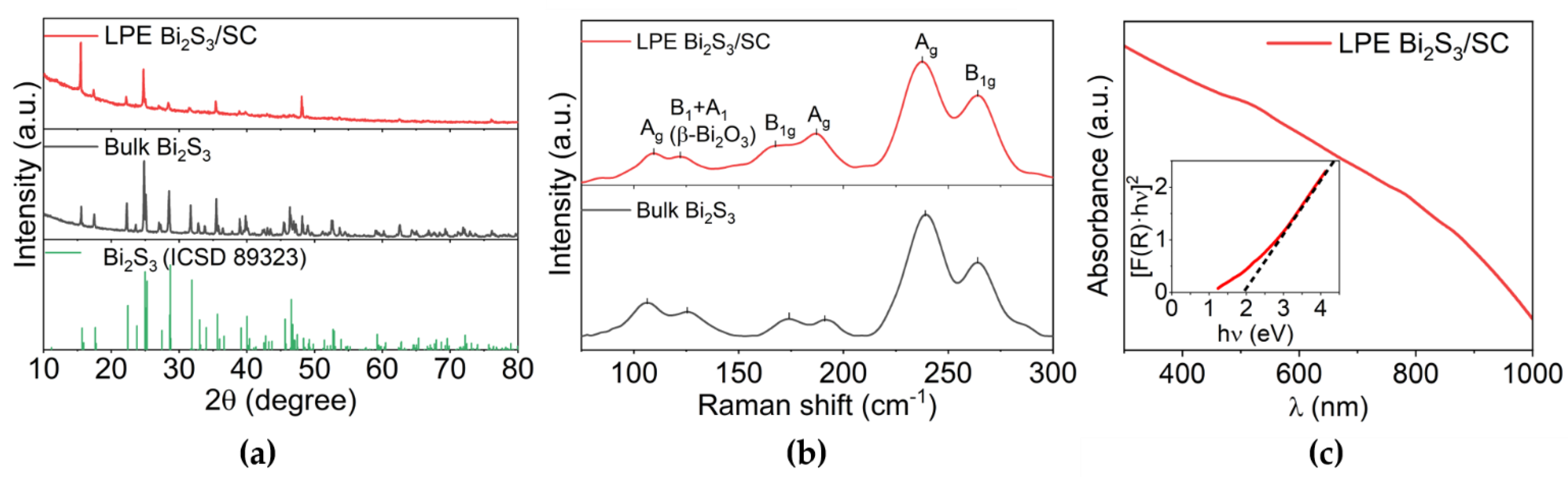
2.1. Surfactant-Assisted LPE of Bi2S3 and Characterization of the Resulting Nanomaterials

Inks of nano-sized Bi2S3 were prepared by surfactant-assisted LPE, as described in detail in Section 3. A typical sample exfoliated with H2O and sodium cholate (LPE Bi2S3/SC) is collected for characterization. TEM analysis reveals the presence of both Bi2S3 NSs and NRs (Figure 1c). The formation of NRs results from the presence of non-covalent vdW-type bonds in the (010) plane and the weak bonding between (100) planes. As shown in Figure 1a,b, (Bi4S6)n chains along the [001] direction are connected through intermolecular bonds [18,22] and these weak bonds are mechanically broken during LPE, leading to the formation of the observed NRs.
Figure 2 shows the X-ray diffraction (XRD) pattern, Raman spectrum and UV–Vis absorption spectrum of LPE Bi2S3. XRD diffractogram of the exfoliated sample reveals the presence of pure orthorhombic Bi2S3 (ICSD number: 89323), which is the same crystalline phase as that of the bulk precursor (Figure 2a). Moreover, an apparent intensity enhancement of the (200) peak at 15.7° is observed compared to the bulk counterpart. In contrast, other characteristic peaks are reduced after LPE, indicating that dimensionally reduced species along the (100) planes are mainly formed. Figure 2b shows the Raman spectra of Bi2S3 before and after LPE. The characteristic peaks of both samples are detected at 170 cm−1, 188 cm−1, 237 cm−1, and 265 cm−1. Therefore, peaks at 188 cm−1 and 237 cm−1 are assigned to longitudinal B1g vibrations, while peaks at 106 cm−1, 170 cm−1, and 265 cm−1 belong to the transverse Ag mode [23]. The exfoliation of the bulk Bi2S3 can be further proved by calculating the Ag to B1g modes intensity ratio at 265 and 237 cm−1, respectively [19]. The reduction in the Ag/B1g value indicates an effective exfoliation of the Bi2S3 crystalline powder (in Figure 2b, a Ag/B1g value of 1.32 is calculated for LPE BisS3 against 1.68 for the bulk starting material). In all spectra, a signal at ~122 cm−1 was recorded; this can be assigned to a Bi-O stretching (B1 and A1 modes) of β-Bi2O3. β-Bi2O3 is not stable at room temperature and standard atmosphere. Thus, it is likely generated by laser irradiation during the Raman measurements [22]. This is supported by the absence of any signal of crystalline bismuth oxides in the XRD patterns (Figure 2a). Figure 2c shows the UV–Vis–NIR spectrum of the LPE Bi2S3 ink in SC/H2O solution. Tauc plot (inset of Figure 2c), calculated from the UV–Vis–NIR spectrum, indicates a widening of the optical band gap to 1.9 eV compared to the band gap of the bulk material (1.3 eV [18]). XPS spectroscopy (Figure S1) was conducted further to investigate the surface elemental composition chemical states of the LPE Bi2S3. For the Bi 4f region, the peaks detected at 163.9 eV and 158.8 eV are assigned to Bi3+ sulphide, while the peaks at 164.8 eV and 159.4 eV are attributed to Bi3+ bound to O [22,24]. Bi 4f region reveals a ~16% of amorphous BiOx (undetectable through XRD), which might be due to the formation of bismuth oxides on the surface of the powder prepared to conduct the XPS analysis, this technique being purely surface sensitive.

2.2. Yield Optimization in Surfactant-Assisted LPE of Bi2S3

The yield in LPE product was studied and optimized by tuning key experimental parameters of the process, such as type and concentration of surfactants, concentration of bulk Bi2S3, exfoliation time, and type of solvents and type of apparatus used for LPE. Zeta potential, particle size, and band gap of the thus produced samples were measured to monitor the colloidal stability of the resulting ink and the outcome of the exfoliation.
The commonly used surfactants for LPE, namely sodium dodecyl sulfate (SDS) and SC, were employed in order to test the influence of the surfactant chemical structure on the yield of the product [21,25]. Considering that the concentration of the surfactant should be below the critical micelle concentration (7.3 mM for SC and 8.0 mM for SDS), to avoid the micelle formation of the surfactant, the concentrations of SC and SDS ranged from 1 mg/mL to 8 mg/mL (Figures S2 and S3 display the as-synthesized samples, Supplementary Materials) [26,27]. A significant difference in yield results with different types of surfactants was observed, as highlighted in Figure 3a (see details in Tables S1 and S2). Under the same surfactant concentration, the yield in LPE Bi2S3 in SC/H2O (LPE Bi2S3/SC) was more than twice higher than in SDS/H2O (LPE Bi2S3/SDS), indicating better stabilization of the exfoliated product in aqueous environment using a bulky molecular surfactant such as SC compared to the more line-shaped SDS [25]. Moreover, the yield in the presence of both surfactants reaches optimized values when the concentration of surfactants is 4 mg/mL, while the yield decreases when the concentrations are above 4 mg/mL. Specifically, the yield of LPE Bi2S3/SC synthesized with 4 mg/mL of SC can reach a percentage as high as 12.3%. Griffin et al. reported that during the LPE of WS2, ionic surfactant concentrations higher than 10 mM can hinder the LPE, since the surfactant causes NSs destabilization due to electrostatic screening [21]. This destabilization might occur in the Bi2S3 dispersions at a surfactant concentration of 8.0 mg/mL as well, since this value is indeed above 10 mM for both surfactants (SC and SDS). Therefore, the yield decreases with the concentration of 8.0 mg/mL independently of the surfactant type. It is also reported that the size and thickness of the 2D layered WS2 are dependent on surfactant concentration. However, a similar aspect on Bi2S3 has not been studied yet, and it is also not considered in our work, with further investigations needed in this direction.
The zeta (ζ) potential, average particle size and band gap values of the LPE Bi2S3 inks are reported in Tables S1 and S2 (Supplementary Materials). Since SC and SDS are anionic surfactants, the zeta potential should have negative values due to the interparticle electrostatic repulsion. As shown in Tables S1 and S2, ζ values for all the samples are between −27 eV and −60 eV, revealing that both SDS and SC surfactants lead to long-term stable suspensions. LPE Bi2S3/SDS showed a slightly higher stability than LPE Bi2S3/SC, which is also reasonably expected by examining the yields. Particle size was determined by dynamic light scattering (DLS). The average size of LPE Bi2S3/SDS is between 183 nm and 220 nm, while LPE Bi2S3/SC is in the range of 140–250 nm, in accordance with TEM analysis reported in Figure 1. The band gap of all the samples is enlarged after LPE. LPE Bi2S3/SDS has a band gap in the 1.5–1.8 eV range and LPE Bi2S3/SC has a gap in the range of 1.7–2.0 eV. These results indirectly indicate that all the samples are exfoliated into nano-sized materials, with an excellent colloidal stability in the final inks.
The effect of initial bulk Bi2S3 concentration was investigated by varying this parameter while keeping constant the others previously discussed at their best values (Figure 3b). The exfoliation yield was stable (~12%) from 0.33 mg/mL to 1.33 mg/mL and, in this range, the concentration of LPE Bi2S3/SC linearly increases with the increasing concentration of bulk Bi2S3 (see Table S3 and Figure S4). A maximum yield of 12.5% is estimated using 1.33 mg/mL of bulk Bi2S3, corresponding to a final concentration of exfoliated material of 0.17 mg/mL. A higher starting material concentration of 2.67 mg/mL causes a dramatic drop in the exfoliation yield to 6.7% and 0.18 mg/mL of final LPE Bi2S3. Therefore, the increase in bulk Bi2S3 concentration is helpful to increase the concentration of the final product up to a certain limit, i.e., when the concentration of raw Bi2S3 is around 2.67 mg/mL. In addition, no significant variation in the colloidal stability, size, and band gap of the resulting nano-inks were observed, suggesting the maintenance of good quality in the exfoliated products, with minimal influence of the starting material concentration on these properties.
Finally, the influence of exfoliation time was explored by performing exfoliations for 3 h, 6 h, and 9 h with the optimized SC and raw Bi2S3 concentration. As shown in Figure 3c, the yield slightly improved by raising the time, reaching a maximum of 14.0% with a product concentration of 0.19 mg/mL. The size distribution, stability and band gap of the nanomaterials in dispersion were independent of the exfoliation time (Figure S5 and Table S4). DLS, zeta potential, and Raman analyses proved that the size distribution, thickness, stability and band gap of the NSs/NRs in dispersion were independent of the exfoliation time (Figure S5 and Table S4).
In addition, other parameters such as the solvent type and apparatus used for LPE were investigated. In the presence of an optimized concentration of SC and raw Bi2S3, different aqueous mixtures of acetone and isopropanol were tested and the results are reported in Table S4 and Figure S6. It is clear that adding an organic solvent leads to a dramatic decrease in the final sample concentration and exfoliation yield compared to H2O [28]. In addition, a destabilization of the colloidal dispersions as well as an increase in the average size occurs, thus indicating water as the best liquid medium to carry out surfactant-assisted LPE of Bi2S3. Ultrasonication and shear mixing are the two methods used for LPE under the same experimental conditions and the results are reported in Table S5 and Figure S7 [29]. No remarkable difference in stability, particle size and band gap were observed, but a significant yield change was detected. Indeed, using a shear mixer (SM) leads to a yield of 12.5%, which is approximately three times more than that achieved by employing a tip sonicator (TS), i.e., 3.9%. Thus, shear mixing results are more efficient for exfoliating Bi2S3 than ultrasonication.
To summarize, the yield in LPE Bi2S3 is influenced by experimental parameters such as type and concentration of surfactant, the concentration of the starting bulk material, exfoliation time, kind of solvents and type of apparatus used. After a systematic investigation, we determined that by using a SM with 1.33 mg/mL of starting Bi2S3 and 4.0 mg/mL of SC in H2O, the final LPE product concentration can reach a value of up to 0.17 mg/mL and a yield of 12.5% after 3 h of exfoliation, which are the optimized LPE parameters to be employed in order to prepare the material for electrocatalytic studies (see next sub-chapter).

2.3. Electrocatalytic Properties of LPE Bi2S3

LPE Bi2S3/SC produced with the optimized method was precipitated from suspension via high-speed centrifugation, washed from residual surfactant and tested for both the HER and the oxygen evolution reaction (OER) in order to understand in which process during water splitting it is more active as an electrocatalyst. Figure 4a displays the linear sweep voltammetry (LSV) performance of LPE Bi2S3/SC. For HER, the sample showed an onset potential of 0.16 V vs. RHE and more than 20 mA/cm2 current at –0.6 V vs. RHE, while the catalytic property towards OER was negligible. A magnification in the range of 1.2–1.8 V vs. RHE shows that the current density is less than 0.05 mA/cm2 at 1.8 V. It is clear that the LPE Bi2S3/SC is a more suitable catalyst for HER than for OER [22]. As for the durability of the LPE Bi2S3/SC, this material appears to be able to sustain at least 15 cycles of cyclic voltammetry at the scan rate of 50 mV/s (Figure S8).
Grazing incidence XRD (GI-XRD) patterns of the catalyst after HER and OER were collected to characterize the crystal structure of the nanosized Bi2S3 after the durability test. As shown in Figure 4b, the sample is constituted of multiple phases, revealing crystalline orthorhombic Bi2S3, FTO (from the electrode substrate) and Na2SO4 (from the electrolyte), after the electrocatalysis. Therefore, the structure and crystalline phase of Bi2S3 remain stable during the catalytic process.
LPE Bi2S3/SC was tested as electrocatalyst for HER at different pH values, as the pH may influence the stability and efficiency of the catalyst (Figure S9) [30]. In acid condition (pH 0), three reduction peaks were revealed, thus indicating the instability of Bi2S3, likely undergoing bismuth (III) reduction at negative potentials, with the generation of metallic Bi. At pH 7 and 14, the LPE material was stable and active as HER electrocatalyst, but the catalytic performance was more efficient in the neutral environment. Furthermore, different catalyst loadings were tested in the neutral electrolyte to study the influence of the amount of material on the electrocatalytic properties. As shown in Figure 5a, all samples’ onset potential is around −0.2 V, except for the sample with 0.72 mg/cm2, which has a minor electrocatalytic performance because of the low amount of the catalyst. However, the overpotential at 1 mA/cm2 heavily depends on the loading amount. In particular, the loading of 1.61 mg/cm2 exhibits the lowest overpotential of 235 mV, which systematically increases, regardless of whether the loading amount decreases or increases. The Tafel slope, shown in Figure 5b, was used to characterize the reaction kinetics [31,32]. The HER includes three steps, namely Volmer step, Heyrovsky step and Tafel step, as shown in the following formulas:
H+ +e + A ⇋ A–H (Volmer step),
A–H + e + H+ ⇋ H2 + A (Heyrovsky step),
2A–H ⇋ 2H2 + A (Tafel step),
where A stands for active sites on the surface of the catalyst.
It is well known that the values of the Tafel slope provides a quantification of the rate determining steps of the electrocatalytic HER. Specifically, 120, 40 and 30 mV/dec were detected and calculated for Volmer, Heyrovsky and Tafel steps, respectively. The Tafel slope of all the samples was more than 120 mV/dec, indicating a Volmer limited HER, and the rate-determining step is the hydrogen adsorption reaction [33]. To compare the samples with different loading amounts, it is clear that the sample with 1.61 mg/cm2 has a much lower Tafel slope of 125 mV/dec, indicating faster HER kinetics than other loadings. However, the onset potential and kinetics are not as good as the benchmark material for HER, i.e., Pt/C (platinum on carbon) [31]. Thus, further optimization of this catalytic material will be needed. The electrocatalytic performances of both bulk and LPE Bi2S3 were compared to evaluate the effect of Bi2S3 size reduction as well (Figure S10). Nano-sized Bi2S3 clearly shows a better electrocatalytic performance than the pristine material, which can be explained by the higher surface area and thus higher number of active sites available for the catalytic reaction [31,34]. The electrocatalytic HER activity of the LPE Bi2S3 is compared with that of Bi2S3 synthesized by other methods in Table 1. It is apparent that the η10 and Tafel slope of LPE Bi2S3 are comparable with that of other Bi2S3 synthesized with different methods (Table 1). This increased overpotential of the LPE Bi2S3 compared to other samples might result from the blocking of active sites by the residue surfactant on the surface.

3. Materials and Methods

3.1. Materials and LPE Processes

The surfactants used for LPE in water were SDS (≥99%, Sigma-Aldrich, Taufkirchen, Germany) and SC (≥99%, Sigma-Aldrich, Taufkirchen, Germany). The starting bulk material was Bi2S3 powder grated from Bi2S3 crystals by an agate mortar (99%, Sigma-Aldrich, Taufkirchen, Germany). Isopropanol, ethanol and fluorine doped tin oxide (FTO) coated glass substrates were purchased from Sigma-Aldrich, Taufkirchen, Germany. Milli-Q water was obtained using a MilliQ ultrapure system in all experiments.
All the exfoliations were performed using a TS or a SM and the samples were cooled to 0 °C with an ice bath during the process. TS was carried on a Baudelin Sonopuls tip sonicator operating with 80% power. SM was carried on an IKA T25 digital shear mixer at 8000 RPM. In all the experiments, the suspension volume was kept fixed at 150 mL. The suspensions obtained after LPE were centrifuged for 20 min at 500 rpm with a Universal 320 Hettich centrifuge. The concentrations of nanomaterials in suspension were calculated by filtration on a PTFE membrane filter. Table S8 summarizes all the exfoliation parameters that varied systematically in this work.

3.2. Characterizations of LPE Bi2S3

The DLS and Zeta potential measurements were performed with a Nano ZS Zetasizer system (Malvern Instruments, Malvern, UK) at 25 °C. UV–Vis–NIR spectroscopy was performed with a Uvikon spectrophotometer from Marlvern, UK. The samples were measured in QS High Precision Cells made of Quartz Suprasil® by Hellma Analytics with a light path of 10 mm. The Tauc methodology for direct band-gap semiconductors was applied to calculate the optical band gap of LPE Bi2S3. Raman spectroscopy was carried out using a Senterra R200–532 from Bruker (Ettlingen, Germany) with a laser emitting at 532 nm. The focus was obtained with a 50x lens at room temperature. The instrumental settings for all the measurements were 7 s of integration time, 90 co-additions, and 0.2 mW of laser power. P-XRD measurements were performed employing a PANalytical X’pert PRO diffractometer (Almelo, The Netherlands) with Cu Kα radiation (λ = 1.5406 Å). GI-XRD diffractograms were carried out on a PANalytical X’Pert PRO MRD (Cu Kα radiation, λ = 1.5406 Å) utilizing a grazing incident geometry. All the diffractograms were recorded with a current of 40 mA and an acceleration voltage of 40 kV. The data were analyzed with the software HighScore Plus with an ICSD database. JEOL JEM-1011 instrument (Tokyo, Japan) with a thermionic W source working at 100 kV was used to perform TEM measurements. XPS measurements were performed with a PHI 5000 VersaProbe II Scanning ESCA Microprobe (Physical Electronics, Chanhassen, MN, USA). A monochromatized Al Kα X-ray source was employed in high power mode, with beam size 1300 μm × 100 μm (X-ray power 100 W). The software CasaXPS was used to perform data analysis [38]. SEM images of the samples were taken on a Carl Zeiss electron microscope (Oberkochen, Germany) with an acceleration voltage of 3 kV and a current of 100 pA.

3.3. Electrocatalytic Analysis

Electrocatalytic analysis was performed using a Potentiostat Galvanostat Autolab from Metrohm. The software used to collect the data was Nova 2.1 from Metrohm. Electrocatalyst inks containing 5.0 mg/mL of the desired material, and 30 µL/mL of Nafion were prepared. The inks were first sonicated for 1 h in a water bath (37 Hz, power 80%), then drop casted on a glassy carbon (GC) with a diameter of 3 mm. The electrochemical cell was set up using the previously prepared GC as a working electrode (WE), a Pt wire as the counter electrode (CE), an Ag/AgCl electrode as a reference electrode (RE), and a nitrogen inlet. A 0.5 M Na2SO4 solution (pH = 7), a 0.5 M H2SO4 solution (pH 0), and a 1.0 M KOH solution (pH = 14) were used as neutral, acidic and alkaline electrolytes, respectively. All the measurements were performed at room temperature (298 K). At the beginning of each measurement, cyclic voltammetries (CV) with a scan rate of 50 mV/s were performed to stabilize the samples. Then, LSV measurements were measured at a scan rate of 10 mV/s.

4. Conclusions

In this work, we systematically studied the surfactant-assisted LPE process on crystalline Bi2S3 and the application of the resulting nano-sized material as an electrocatalyst for HER. SC-assisted LPE in H2O was used to produce a stable colloidal ink, and the NSs and NRs contained there are sized around 200 nm. A broadening of the optical band gap up to 1.9 eV occurs from the bulk because of the formation of low-dimensional species. By tuning the experimental parameters, it was possible to reach exfoliation yields of up to 14% (0.19 mg/mL). To further explore the LPE of Bi2S3 with the aim of obtaining even better yields, more types of cationic and also non-ionic surfactants will be worthy of texting in next works, such as hexadecyltrimethylammonium bromide, polyvinylpyrrolidone and polymethyl methacrylate [21,39,40]. In addition, the availability of nano-sized Bi2S3 makes it possible to combine it with other 2D layered materials such as MoS2 and WS2 to form vdW heterojunctions, which can have even better electrocatalytic properties than the individual species [41].
The optimized LPE Bi2S3 sample (prepared with a SM for 3 h, from 1.33 mg/mL of starting Bi2S3 and 4.0 mg/mL of SC in H2O, obtained with ayield of 12.5% and final ink concentration of 0.17 mg/mL) was applied as a promising electrocatalyst for HER in neutral conditions, demonstrating an overpotential of 235 mV at the current density of 1 mA/cm2. The performance of low-dimensional Bi2S3 is definitely higher than that of its bulk counterpart. This result reveals the potential of this material in its nano-confined form to display interesting catalytic properties, which deserve to be better explored in the near future.

Supplementary Materials

The following supporting information can be downloaded at: https://www.mdpi.com/article/10.3390/catal13030551/s1, Figure S1: XPS spectra for LPE Bi2S3/SC; Figure S2: Pictures of Bi2S3 suspensions prepared with different concentrations of SDS; Figure S3: Pictures of Bi2S3 suspensions prepared with different concentrations of SC; Figure S4: Pictures of nano-sized LPE Bi2S3 with different concentrations of bulk Bi2S3; Figure S5: Pictures of nano-sized LPE Bi2S3 with different exfoliation time; Figure S6: Pictures of nano-sized LPE Bi2S3 with different solvents; Figure S7: Pictures of nano-sized LPE Bi2S3 with different exfoliation methods; Figure S8: CV curves of LPE Bi2S3/SC (1.61 mg/cm2) and SEM images before and after the CV. Figure S9: LSV (scan rate 10 mV/s) curves of LPE Bi2S3/SC (1.61 mg/cm2) for HER electrocatalysis in electrolytes with different pH values; Figure S10: LSV curves (scan rate 10 mV/s) of LPE Bi2S3/SC and bulk Bi2S3 (1.61 mg/cm2) as HER electrocatalysts in neutral electrolyte (Na2SO4 0.5 M). Table S1: Zeta potential (ζ), average size, band gap, concentration and yield of nano-sized LPE Bi2S3 with different concentrations of SDS surfactant; Table S2: Zeta potential (ζ), average size, band gap, concentration and yield of nano-sized LPE Bi2S3 with different concentrations of SC; Table S3: Zeta potential (ζ), average size, band gap, concentration and yield of nano-sized LPE Bi2S3 with different concentrations of bulk Bi2S3; Table S4: Zeta potential (ζ), average size, band gap, concentration and yield of nano-sized LPE Bi2S3 with different exfoliation time; Table S5: Zeta potential (ζ), average size, band gap, concentration and yield of nano-sized LPE Bi2S3 with different solvents; Table S6: Zeta potential (ζ), average size, band gap, concentration and yield of nano-sized LPE Bi2S3 with different exfoliation methods; Table S7: Overpotential at 1 mA/cm2 and Tafel slope referred to LPE Bi2S3/SC HER activity in neutral electrolyte; Table S8: Summary of the experimental parameters of all the exfoliations in this work.

Author Contributions

Conceptualization, M.W. and T.G.; methodology, M.W., M.P., M.C., Z.L. and J.G.; formal analysis, M.W., M.P., M.C. and J.G.; resources, T.G.; data curation, M.W.; writing—original draft preparation, M.W. and M.P.; writing—review and editing, M.W. and T.G.; visualization, M.W.; supervision, T.G. and M.W.; project administration, T.G.; funding acquisition, M.W. and T.G. All authors have read and agreed to the published version of the manuscript.

Funding

This research was funded by Hessisches Ministerium für Wissenschaft und Kunst (HMWK) through the programme Marie Skłodowska-Curie-Stipendium Hessen. T. G. also acknowledges the support of the European Commission through the H2020 FET-PROACTIVE-EIC-07-2020 project LIGHT-CAP (grant agreement No. [101017821]) and of the European Research Council through the ERC StG project JANUS BI (grant agreement No. [101041229]).

Data Availability Statement

The data presented in this work are available upon request from the corresponding author.

Acknowledgments

T.G. would like to thank the Justus Liebig University Giessen for the Herbert-Stolzenberg-Preis for research 2022.

Conflicts of Interest

The authors declare no conflict of interest.

References

  1. Wang, M.; Dang, Z.; Prato, M.; Shinde, D.V.; De Trizio, L.; Manna, L. Ni-Co-S-Se Alloy Nanocrystals: Influence of the Composition on Their in Situ Transformation and Electrocatalytic Activity for the Oxygen Evolution Reaction. ACS Appl. Nano Mater. 2018, 1, 5753–5762. [Google Scholar] [CrossRef]
  2. Wang, S.; Robertson, A.; Warner, J.H. Atomic Structure of Defects and Dopants in 2D Layered Transition Metal Dichalcogenides. Chem. Soc. Rev. 2018, 47, 6764–6794. [Google Scholar] [CrossRef]
  3. Lin, C.; Liu, H.; Guo, M.; Zhao, Y.; Su, X.; Zhang, P.; Zhang, Y. Plasmon-Induced Broad Spectrum Photocatalytic Overall Water Splitting: Through Non-Noble Bimetal Nanoparticles Hybrid with Reduced Graphene Oxide. Colloids Surf. A Physicochem. Eng. Asp. 2022, 646, 128962. [Google Scholar] [CrossRef]
  4. Zhang, B.; Wu, M.; Zhang, L.; Xu, Y.; Hou, W.; Guo, H.; Wang, L. Isolated Transition Metal Nanoparticles Anchored on N-Doped Carbon Nanotubes as Scalable Bifunctional Electrocatalysts for Efficient Zn–Air Batteries. J. Colloid Interface Sci. 2023, 629, 640–648. [Google Scholar] [CrossRef] [PubMed]
  5. Jariwala, D.; Sangwan, V.K.; Lauhon, L.J.; Marks, T.J.; Hersam, M.C. Emerging Device Applications for Semiconducting Two-Dimensional Transition Metal Dichalcogenides. ACS Nano 2014, 8, 1102–1120. [Google Scholar] [CrossRef] [PubMed] [Green Version]
  6. Chia, X.; Eng, A.Y.S.; Ambrosi, A.; Tan, S.M.; Pumera, M. Electrochemistry of Nanostructured Layered Transition-Metal Dichalcogenides. Chem. Rev. 2015, 115, 11941–11966. [Google Scholar] [CrossRef] [PubMed] [Green Version]
  7. Wang, Q.H.; Kalantar-Zadeh, K.; Kis, A.; Coleman, J.N.; Strano, M.S. Electronics and Optoelectronics of Two-Dimensional Transition Metal Dichalcogenides. Nat. Nanotechnol. 2012 711 2012, 7, 699–712. [Google Scholar] [CrossRef]
  8. Zhang, Y.; Wang, Y.; Guo, C.; Wang, Y. Molybdenum Carbide-Based Photocatalysts: Synthesis, Functionalization, and Applications. Langmuir 2022, 38, 12739–12756. [Google Scholar] [CrossRef]
  9. Wang, Y.; Zhao, Y.; Ding, X.; Qiao, L. Recent Advances in the Electrochemistry of Layered Post-Transition Metal Chalcogenide Nanomaterials for Hydrogen Evolution Reaction. J. Energy Chem. 2021, 60, 451–479. [Google Scholar] [CrossRef]
  10. Xie, Y.; Zhou, Y.; Gao, C.; Liu, L.; Zhang, Y.; Chen, Y.; Shao, Y. Construction of AgBr/BiOBr S-Scheme Heterojunction Using Ion Exchange Strategy for High-Efficiency Reduction of CO2 to CO under Visible Light. Sep. Purif. Technol. 2022, 303, 122288. [Google Scholar] [CrossRef]
  11. Yang, J.; Wang, C.; Ju, H.; Sun, Y.; Xing, S.; Zhu, J.; Yang, Q. Integrated Quasiplane Heteronanostructures of MoSe2/Bi2Se3 Hexagonal Nanosheets: Synergetic Electrocatalytic Water Splitting and Enhanced Supercapacitor Performance. Adv. Funct. Mater. 2017, 27, 1703864. [Google Scholar] [CrossRef]
  12. Qu, Q.; Liu, B.; Liang, J.; Li, H.; Wang, J.; Pan, D.; Sou, I.K. Expediting Hydrogen Evolution through Topological Surface States on Bi2Te3. ACS Catal. 2020, 10, 2656–2666. [Google Scholar] [CrossRef] [Green Version]
  13. Ambrosi, A.; Sofer, Z.; Luxa, J.; Pumera, M. Exfoliation of Layered Topological Insulators Bi2Se3 and Bi2Te3 via Electrochemistry. ACS Nano 2016, 10, 11442–11448. [Google Scholar] [CrossRef]
  14. Tan, S.M.; Mayorga-Martinez, C.C.; Sofer, Z.; Pumera, M. Bipolar Electrochemistry Exfoliation of Layered Metal Chalcogenides Sb2S3 and Bi2S3 and Their Hydrogen Evolution Applications. Chem. A Eur. J. 2020, 26, 6479–6483. [Google Scholar] [CrossRef] [PubMed]
  15. Wang, Y.; Chen, J.; Wang, P.; Chen, L.; Chen, Y.B.; Wu, L.M. Syntheses, Growth Mechanism, and Optical Properties of [001] Growing Bi2S3 Nanorods. J. Phys. Chem. C 2009, 113, 16009–16014. [Google Scholar] [CrossRef]
  16. Coleman, J.N.; Lotya, M.; O’Neill, A.; Bergin, S.D.; King, P.J.; Khan, U.; Young, K.; Gaucher, A.; De, S.; Smith, R.J.; et al. Two-Dimensional Nanosheets Produced by Liquid Exfoliation of Layered Materials. Science 2011, 331, 568–571. [Google Scholar] [CrossRef] [Green Version]
  17. Dhar, N.; Syed, N.; Mohiuddin, M.; Jannat, A.; Zavabeti, A.; Zhang, B.Y.; Datta, R.S.; Atkin, P.; Mahmood, N.; Esrafilzadeh, D.; et al. Exfoliation Behavior of van Der Waals Strings: Case Study of Bi2S3. ACS Appl. Mater. Interfaces 2018, 10, 42603–42611. [Google Scholar] [CrossRef] [PubMed]
  18. Clark, R.M.; Kotsakidis, J.C.; Weber, B.; Berean, K.J.; Carey, B.J.; Field, M.R.; Khan, H.; Ou, J.Z.; Ahmed, T.; Harrison, C.J.; et al. Exfoliation of Quasi-Stratified Bi2S3 Crystals into Micron-Scale Ultrathin Corrugated Nanosheets. Chem. Mater. 2016, 28, 8942–8950. [Google Scholar] [CrossRef]
  19. Guo, Y.; Zhao, Q.; Yao, Z.; Si, K.; Zhou, Y.; Xu, X. Efficient Mixed-Solvent Exfoliation of Few-Quintuple Layer Bi2S3 and Its Photoelectric Response. Nanotechnology 2017, 28, 335602. [Google Scholar] [CrossRef]
  20. Gupta, A.; Arunachalam, V.; Vasudevan, S. Water Dispersible, Positively and Negatively Charged MoS2 Nanosheets: Surface Chemistry and the Role of Surfactant Binding. J. Phys. Chem. Lett. 2015, 6, 739–744. [Google Scholar] [CrossRef]
  21. Griffin, A.; Nisi, K.; Pepper, J.; Harvey, A.; Szydłowska, B.M.; Coleman, J.N.; Backes, C. Effect of Surfactant Choice and Concentration on the Dimensions and Yield of Liquid-Phase-Exfoliated Nanosheets. Chem. Mater. 2020, 32, 2852–2862. [Google Scholar] [CrossRef]
  22. Ni, J.; Bi, X.; Jiang, Y.; Li, L.; Lu, J. Bismuth Chalcogenide Compounds Bi2×3 (X=O, S, Se): Applications in Electrochemical Energy Storage. Nano Energy 2017, 34, 356–366. [Google Scholar] [CrossRef] [Green Version]
  23. Yang, D.; Lu, C.; Ma, J.; Luo, M.; Zhao, Q.; Jin, Y.; Xu, X. Enhanced Nonlinear Saturable Absorption from Type III van Der Waals Heterostructure Bi2S3/MoS2 by Interlayer Electron Transition. Appl. Surf. Sci. 2021, 538, 147989. [Google Scholar] [CrossRef]
  24. Wang, M.; Osella, S.; Brescia, R.; Liu, Z.; Gallego, J.; Cattelan, M.; Crisci, M.; Agnoli, S.; Gatti, T. 2D MoS2/BiOBr van Der Waals Heterojunctions by Liquid-Phase Exfoliation as Photoelectrocatalysts for Hydrogen Evolution. Nanoscale 2023, 15, 522–531. [Google Scholar] [CrossRef] [PubMed]
  25. Crisci, M.; Boll, F.; Merola, L.; Pflug, J.J.; Liu, Z.; Gallego, J.; Lamberti, F.; Gatti, T. Nanostructured 2D WS2@PANI Nanohybrids for Electrochemical Energy Storage. Front. Chem. 2022, 10, 1132. [Google Scholar] [CrossRef]
  26. Moroi, Y.; Motomura, K.; Matuura, R. The Critical Micelle Concentration of Sodium Dodecyl Sulfate-Bivalent Metal Dodecyl Sulfate Mixtures in Aqueous Solutions. J. Colloid Interface Sci. 1974, 46, 111–117. [Google Scholar] [CrossRef]
  27. Reis, S.; Moutinho, C.G.; Matos, C.; De Castro, B.; Gameiro, P.; Lima, J.L.F.C. Noninvasive Methods to Determine the Critical Micelle Concentration of Some Bile Acid Salts. Anal. Biochem. 2004, 334, 117–126. [Google Scholar] [CrossRef]
  28. Park, S.-H.; Leka, K.D.; Kusano, K.; Ackermann, M.; Ajello, M.; Allafort, A.; Yi, M.; Shen, Z.; Zhang, X.; Ma, S. Achieving Concentrated Graphene Dispersions in Water/Acetone Mixtures by the Strategy of Tailoring Hansen Solubility Parameters. J. Phys. D Appl. Phys. 2012, 46, 025301. [Google Scholar] [CrossRef] [Green Version]
  29. Niu, L.; Coleman, J.N.; Zhang, H.; Shin, H.; Chhowalla, M.; Zheng, Z. Production of Two-Dimensional Nanomaterials via Liquid-Based Direct Exfoliation. Small 2016, 12, 272–293. [Google Scholar] [CrossRef]
  30. Zhou, Z.; Pei, Z.; Wei, L.; Zhao, S.; Jian, X.; Chen, Y. Electrocatalytic Hydrogen Evolution under Neutral PH Conditions: Current Understandings, Recent Advances, and Future Prospects. Energy Environ. Sci. 2020, 13, 3185–3206. [Google Scholar] [CrossRef]
  31. Shinagawa, T.; Garcia-Esparza, A.T.; Takanabe, K. Insight on Tafel Slopes from a Microkinetic Analysis of Aqueous Electrocatalysis for Energy Conversion. Sci. Rep. 2015, 5, 1–21. [Google Scholar] [CrossRef] [Green Version]
  32. Murthy, A.P.; Theerthagiri, J.; Madhavan, J. Insights on Tafel Constant in the Analysis of Hydrogen Evolution Reaction. J. Phys. Chem. C 2018, 122, 23943–23949. [Google Scholar] [CrossRef]
  33. Bao, F.; Kemppainen, E.; Dorbandt, I.; Bors, R.; Xi, F.; Schlatmann, R.; van de Krol, R.; Calnan, S. Understanding the Hydrogen Evolution Reaction Kinetics of Electrodeposited Nickel-Molybdenum in Acidic, Near-Neutral, and Alkaline Conditions. ChemElectroChem 2021, 8, 195–208. [Google Scholar] [CrossRef]
  34. Chen, Y.-Z.; Wang, C.; Wu, Z.-Y.; Xiong, Y.; Xu, Q.; Yu, S.-H.; Jiang, H.-L.; Chen, Y.; Wang, C.; Wu, Z.; et al. From Bimetallic Metal-Organic Framework to Porous Carbon: High Surface Area and Multicomponent Active Dopants for Excellent Electrocatalysis. Adv. Mater. 2015, 27, 5010–5016. [Google Scholar] [CrossRef] [PubMed]
  35. Zhou, L.; Yang, T.; Chen, S.; Gao, J.; Wang, X.; He, P.; Lei, H.; Yang, D.; Dong, F.; Jia, L.; et al. Tunably Fabricated Nanotremella-like Bi2S3/MoS2: An Excellent and Highly Stable Electrocatalyst for Alkaline Hydrogen Evolution Reaction. Int. J. Hydrogen Energy 2020, 45, 9535–9545. [Google Scholar] [CrossRef]
  36. Li, J.; Wang, B.; Wang, T.; Zhao, Y.; Song, T.; Zhang, L.; Cheng, X. Construction of Scaffold-like Au@MoS2/Bi2S3 Networks with Superior Electro-Catalytic Performance. J. Alloys Compd. 2020, 831, 154829. [Google Scholar] [CrossRef]
  37. Zhang, H.; Diao, J.; Ouyang, M.; Yadegari, H.; Mao, M.; Wang, J.; Henkelman, G.; Xie, F.; Riley, D.J.; Zhang, H.; et al. Enhancing the Performance of Bi2S3 in Electrocatalytic and Supercapacitor Applications by Controlling Lattice Strain. Adv. Funct. Mater. 2022, 32, 2205974. [Google Scholar] [CrossRef]
  38. Fairley, N.; Fernandez, V.; Richard-Plouet, M.; Guillot-Deudon, C.; Walton, J.; Smith, E.; Flahaut, D.; Greiner, M.; Biesinger, M.; Tougaard, S.; et al. Systematic and Collaborative Approach to Problem Solving Using X-Ray Photoelectron Spectroscopy. Appl. Surf. Sci. Adv. 2021, 5, 100112. [Google Scholar] [CrossRef]
  39. Narayan, R.; Kim, S.O. Surfactant Mediated Liquid Phase Exfoliation of Graphene. Nano Converg. 2015, 2, 1–19. [Google Scholar] [CrossRef] [Green Version]
  40. Hu, C.X.; Shin, Y.; Read, O.; Casiraghi, C. Dispersant-Assisted Liquid-Phase Exfoliation of 2D Materials beyond Graphene. Nanoscale 2021, 13, 460–484. [Google Scholar] [CrossRef]
  41. Bahadur, A.; Iqbal, S.; Alsaab, H.O.; Awwad, N.S.; Ibrahium, H.A. Designing a Novel Visible-Light-Driven Heterostructure Ni-ZnO/S-g-C3N4 Photocatalyst for Coloured Pollutant Degradation. RSC Adv. 2021, 11, 36518–36527. [Google Scholar] [CrossRef] [PubMed]
Figure 1. Crystal structure of Bi2S3: (a) top view from the a-axis and (b) top view from the c-axis. (c) TEM images of LPE Bi2S3/SC, demonstrating the presence of both Bi2S3 NSs and monodimensional structures such as NRs.
Catalysts 13 00551 g001
Figure 2. (a) P−XRD patterns, (b) Raman spectra and (c) UV–VIis–NIR absorption spectrum of LPE Bi2S3/SC. Tauc plot of LPE Bi2S3/SC is inserted in Figure 2c. For XRD and Raman, comparison with bulk Bi2S3 is reported.
Catalysts 13 00551 g002
Figure 3. Optimization of the surfactant-assisted LPE process for Bi2S3. (a) Yield in nano-sized LPE Bi2S3 with different types and concentrations of surfactants (SC red line, SDS blue line) determined starting from 0.33 mg/mL of bulk Bi2S3 and exfoliation time of 3 h. (b) Exfoliation yield (black line) and concentration of LPE Bi2S3 in 4 mg/mL of SC/H2O suspensions (red line) with different concentrations of starting bulk Bi2S3 (exfoliation time = 3 h). (c) Exfoliation yield (black line) and concentration of LPE Bi2S3 in 4 mg/mL SC/H2O suspensions (red line) after different exfoliation times (starting Bi2S3 concentration = 1.5 mg/mL).
Catalysts 13 00551 g003
Figure 4. (a) Polarization curve (scan rate 10 mV/s) of LPE Bi2S3/SC NSs (1.61 mg/cm2) for HER and OER electrocatalysis at pH 7 (Na2SO4 0.5 M). Inset exhibits the magnification of the polarization curve of 1.2-1.8 V vs. RHE; (b) GI-XRD patterns of LPE Bi2S3/SC after HER and OER. Reference patterns of orthorhombic Bi2S3 (ICSD 89323), FTO (ICSD 160667) and Na2SO4 (ICSD 2895) are reported for the sake of clarity.
Catalysts 13 00551 g004
Figure 5. (a) LSV curves (scan rate 10 mV/s) measured in neutral condition (Na2SO4 0.5 M) using different loadings of LPE Bi2S3/SC. Pt/C HER activity is reported as a reference; (b) Tafel plots from LSV curves reported in Figure 5a.
Catalysts 13 00551 g005
Table 1. Comparison of electrocatalytic HER performance for different Bi2S3 electrocatalysts.
Catalystsη10/VTafel Slope/mV dec−1References
Bi2S3 by hydrothermal synthesis0.4273[35]
Bi2S3 by solvothermal synthesis0.3584[36]
Lattice expanded Bi2S3 by solvothermal synthesis0.187.2[37]
Bi2S3 by bipolar electrochemical exfoliation0.45/[14]
Bi2S3 by LPE (this work)0.45125This work
Disclaimer/Publisher’s Note: The statements, opinions and data contained in all publications are solely those of the individual author(s) and contributor(s) and not of MDPI and/or the editor(s). MDPI and/or the editor(s) disclaim responsibility for any injury to people or property resulting from any ideas, methods, instructions or products referred to in the content.

