Article

Integrated Modeling of the Catalytic Aquathermolysis Process to Evaluate the Efficiency in a Porous Medium by the Example of a Carbonate Extra-Viscous Oil Field

by
Ilgiz F. Minkhanov
1,*,
Vladislav V. Chalin
1,
Aidar R. Tazeev
1,
Alexander V. Bolotov
1,
Irek I. Mukhamatdinov
1,
Sergey A. Sitnov
1,
Alexey V. Vakhin
1,
Mikhail A. Varfolomeev
1,*,
Sergey I. Kudryashov
2,
Igor S. Afanasiev
2,
Alexey V. Solovyev
2,
Georgiy V. Sansiev
2,
Dmitry A. Antonenko
2,
Kirill A. Dubrovin
2 and
Iaroslav O. Simakov
2
1
Institute of Geology and Petroleum Technologies, Kazan (Volga Region) Federal University, 18 Kremlyovskaya Str., 420008 Kazan, Russia
2
JSC Zarubezhneft, Basmanniy Municipal District Intra-City Area, 9 Armianskiy Pereulok, 101000 Moscow, Russia
*
Authors to whom correspondence should be addressed.
Catalysts 2023, 13(2), 283; https://doi.org/10.3390/catal13020283
Submission received: 4 January 2023 / Revised: 19 January 2023 / Accepted: 24 January 2023 / Published: 27 January 2023
(This article belongs to the Special Issue Catalysis for Bitumen/Heavy Oil Upgrading and Petroleum Refining)

Abstract

:
In order to evaluate the efficiency of the catalytic aquathermolysis process, physical modeling was carried out on bituminous sediments of Paleocene–Miocene carbonate rocks, characterized by the presence of open and closed fractures. In this context, three filtration experiments were performed on an unextracted reservoir model with extra-viscous oil (EVO). Prior to the experiments, the mineral composition of the rock was determined by X-ray diffraction analysis (XRD) and the content of organic matter and coking products was determined before and after the experiment by thermogravimetric analysis (TGA) as well as the group composition of oil (SARA) before and after the experiment by nuclear magnetic resonance (NMR), gas composition at the fluid separation line, and oil displacement coefficient (ODC). The results of the conducted experiments show that the efficiency of displacement of extraviscous oil could be significantly increased by the use of a solvent and the combined use of a solvent and a catalyst (+9.3% and +17.1% of the oil displacement coefficient, respectively), which is associated with the processes of oil refining.

1. Introduction

World experience shows that the most widespread and effective methods for development of extra-viscous oil (EVO) reservoirs are thermal, namely steam-thermal treatment (STT). However, this technology has several drawbacks, which reduce its technical and economic efficiency. The main disadvantages of STT are high cost of steam generation and greenhouse gas emissions during its production, rapid watering of the reservoir, while the produced oil after cooling still has high viscosity and density, which complicates its further treatment and transportation.
In work [1], various variants of EVO development using thermal methods were considered. This included the authors’ conducted experiments on unextracted rock, where hot water at 100 °C was used as the working agent. However, due to high oil viscosity (600,000 cP), no oil displacement was observed.
A comparison of the methods of EVO extraction is presented in work [2]. During the work three experiments were carried out: displacement with water, exposure with hot water, and steam. In contrast to the first and second experiments, steam injection demonstrated efficiency, with a displacement rate of 13.4% (no oil displacement was observed in the first and second experiments) [3,4].
To increase the efficiency of extra-viscous oil extraction by steam-treatment methods, it is advisable to use combined steam injection with various reagent additives. Such additives include solvents and catalysts [5,6,7,8,9]. As it is well known, solvents are an effective additive for the process of increasing EVO production, where it is injected together or sequentially with steam [10,11,12]. After injection, the solvent condenses with the steam at the interface with the oil-saturated rock and further mixes with the oil, resulting in a reduction in oil viscosity and an increase in oil production rate. There are generally five types of solvent injection applications: LASER (liquid addition to steam for enhancing recovery), SAS (steam-alternating solvent), ES-SAGD (expanding solvent-SAGD), SAP (Solvent-Aided Process), and SESF (Solvent Enhanced Steam Flooding).
In the work [13], the authors described the results of filtration experiments on steam injection under different permeability, low initial oil saturation, and content of clay minerals in the rock. Steam injection without additives was ineffective and no oil displacement was observed. However, when adding a rim of the solvent in experiments with similar conditions, the displacement rate was 61–71%, which confirms the effectiveness of its use in conditions of EVO.
The key point is also the choice of solvent type to maximize oil production efficiency. One of the main factors is reservoir temperature [14,15].
The use of catalysts together with steam injection in in situ oil enrichment provides many advantages, one of them being an increase in the degree of oil recovery [16,17,18].
Catalysts stimulate hydrogenation, hydrogenolysis, hydrolysis, and cracking reactions, leading to improved physical, chemical, and rheological characteristics of oil. The formation of catalytic metals enhances the ability of the rock mineral skeleton to provide oil conversion already in the reservoir. This not only increases reservoir coverage by reducing the molecular weight of resins and asphaltenes, but also irreversibly reduces the viscosity of the produced oil and its content of hard-to-process components [19,20,21,22,23,24,25]. In practice, various types of catalysts are used (mineral, water-soluble, oil-soluble, and dispersed), while dispersed catalysts are the most effective in terms of reducing viscosity [26].
In work [27], studies were conducted to evaluate the effectiveness of aquathermolysis catalysts based on salicylic acid and chloride salts. As a result of the interaction of the catalyst with oil, the viscosity of the latter was reduced by 91.5% due to the breaking of C-C, C-N and C-S bonds, and the results of TGA and DSC (differential scanning calorimetry) showed a significant decrease in the proportion of macromolecules of heavy oil.
In work [13] the efficiency of steam injection with solvent and catalyst compared to standard steam injection was considered. The experiments demonstrate an increase in the displacement coefficient by at least 1.5 times.
Laboratory data from previous studies were confirmed by the results of an industrial experiment [28]. For a nickel-based catalytic composition, a reduction in the content of heavy components—resins and asphaltenes—is achieved under reservoir conditions. Now, the most important task is to optimize the cost of the catalytic composition by replacing expensive nickel with iron in its composition. To this end, there is an increasing need to study the effectiveness of catalytic compositions with different ratios of nickel and iron and reduce the cost of the resulting composition without losing the efficiency that was when using a monometallic precursor of a nickel-based catalyst.
The purpose of this work is to study the effect of nanodisperse iron and nickel sulfides on the transformation of the composition of high-viscosity oil in the presence of rock-forming minerals in hydrothermal conditions by determining the displacement coefficient of oil, its properties, and composition after exposure to steam.

2. Results and Discussion

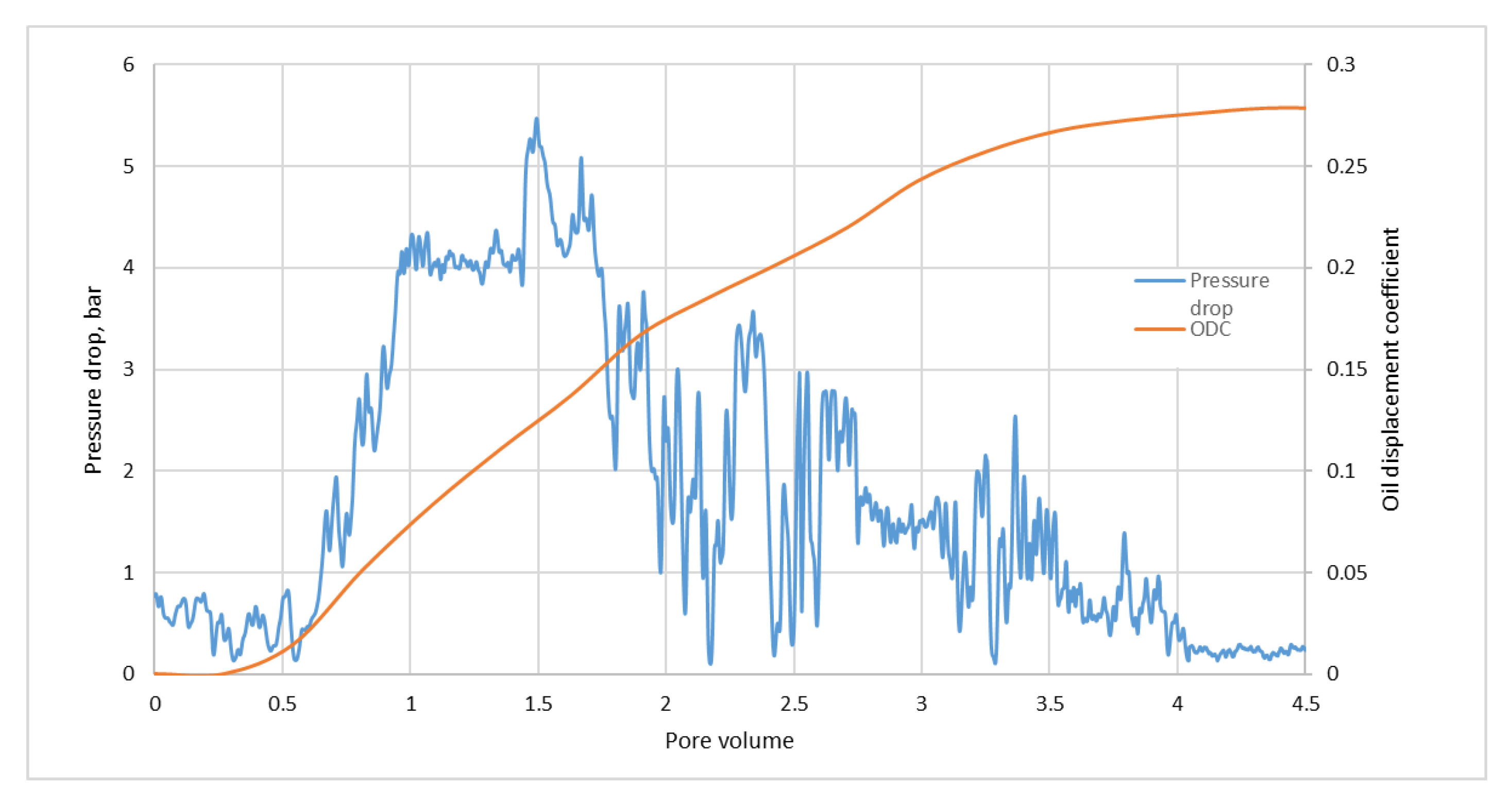
Results of filtration experiment № 1. Steam injection at a temperature of 300 °C.
The dynamics of changes in pressure drop and oil displacement coefficient in the first experiment are shown in Figure 1.
The maximum value of pressure drop is 5.3 bar. The oil displacement coefficient reaches its maximum value at pumping 4.5 pore volume (PV) of steam, and the greatest growth of the displacement coefficient falls on the first 3 PV. The mass of displaced oil during the experiment was 41.9 g, and the displacement coefficient is 27.9%.
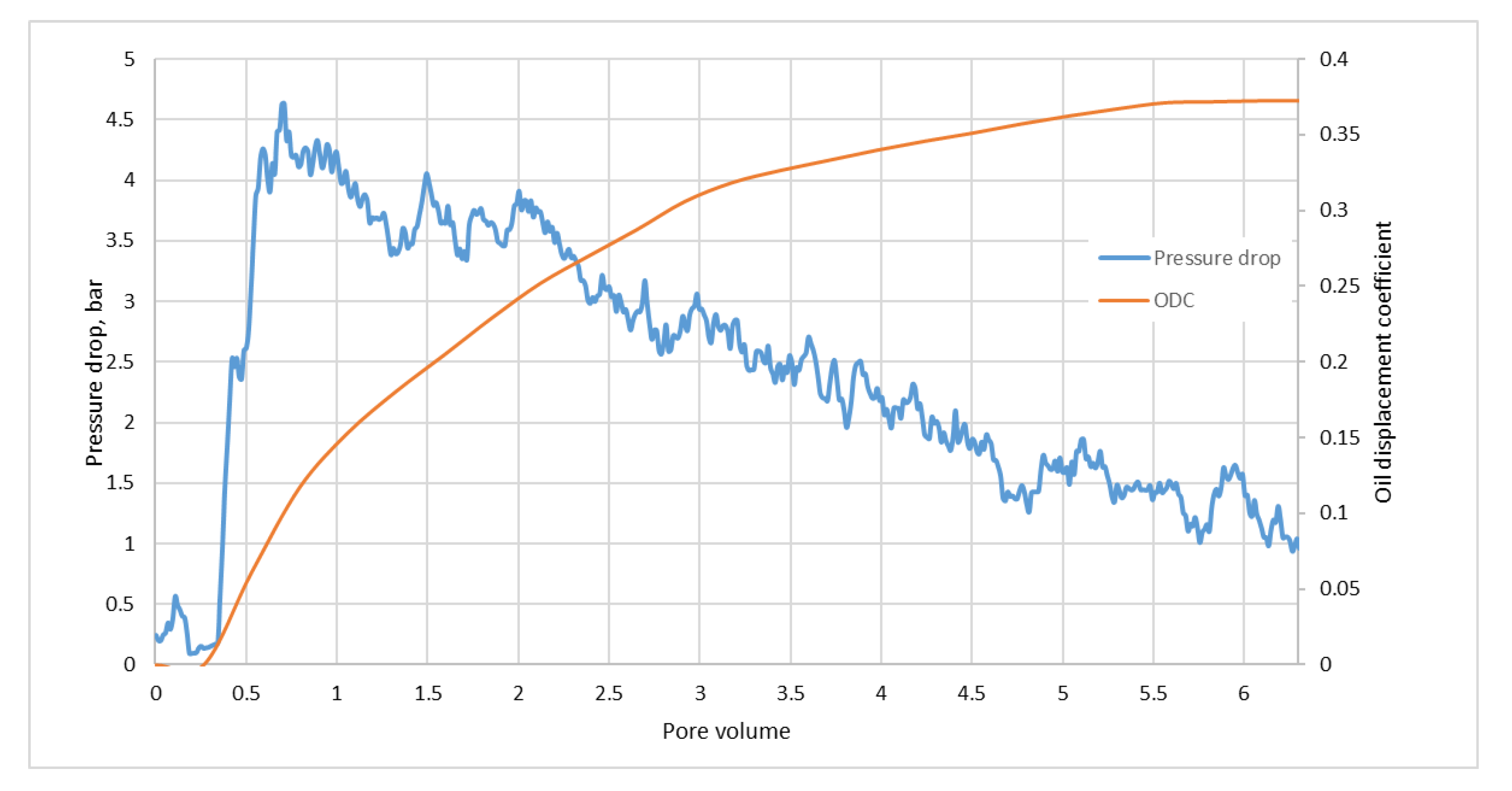
Results of filtration experiment № 2. Steam injection with solvent at 300 °C.
The dynamics of changes in pressure drop and oil displacement coefficient in the second experiment are shown in Figure 2.
After pumping 0.5 PV, there was a sharp increase in pressure drop to 6 bar. With further injection of steam, the pressure drop in the model decreases to 1 bar. The largest oil displacement corresponds to the interval 0.3–3.0 PV. During the experiment, 55.9 g of oil was displaced, the displacement coefficient of 37.2% was achieved.
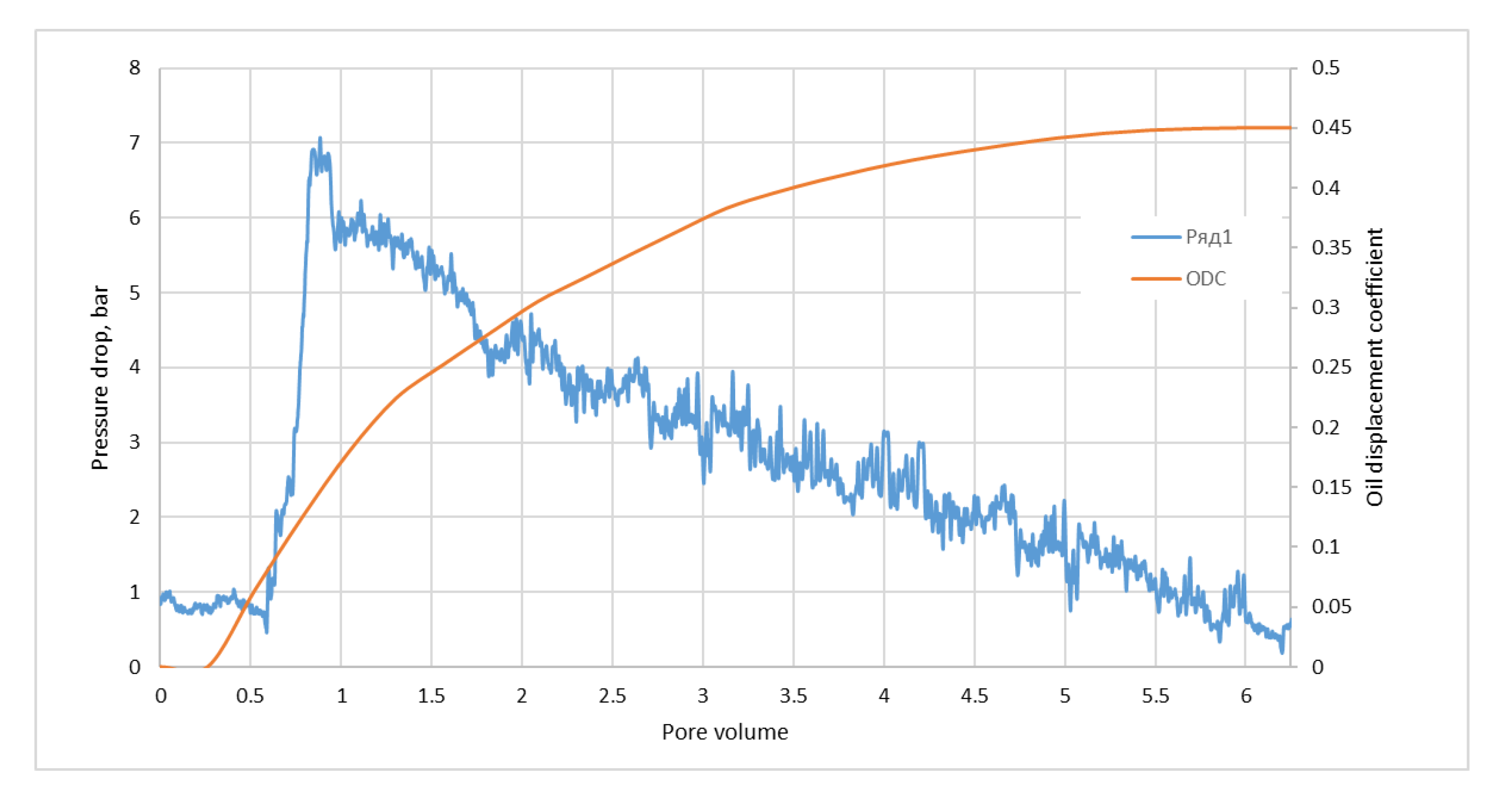
Results of filtration experiment № 3. Steam injection with solvent and catalyst addition at 300 °C.
The dynamics of changes in pressure drop and oil displacement coefficient in the third experiment are shown in Figure 3.
In the experiment, after pumping 0.5 PV there was an increase in depression to 7 bars. After pumping 1 PV of steam, the depression in the model steadily decreased to 0.5 bar. During the experiment 67.6 g of oil was displaced, and oil displacement coefficient is 45.0%.
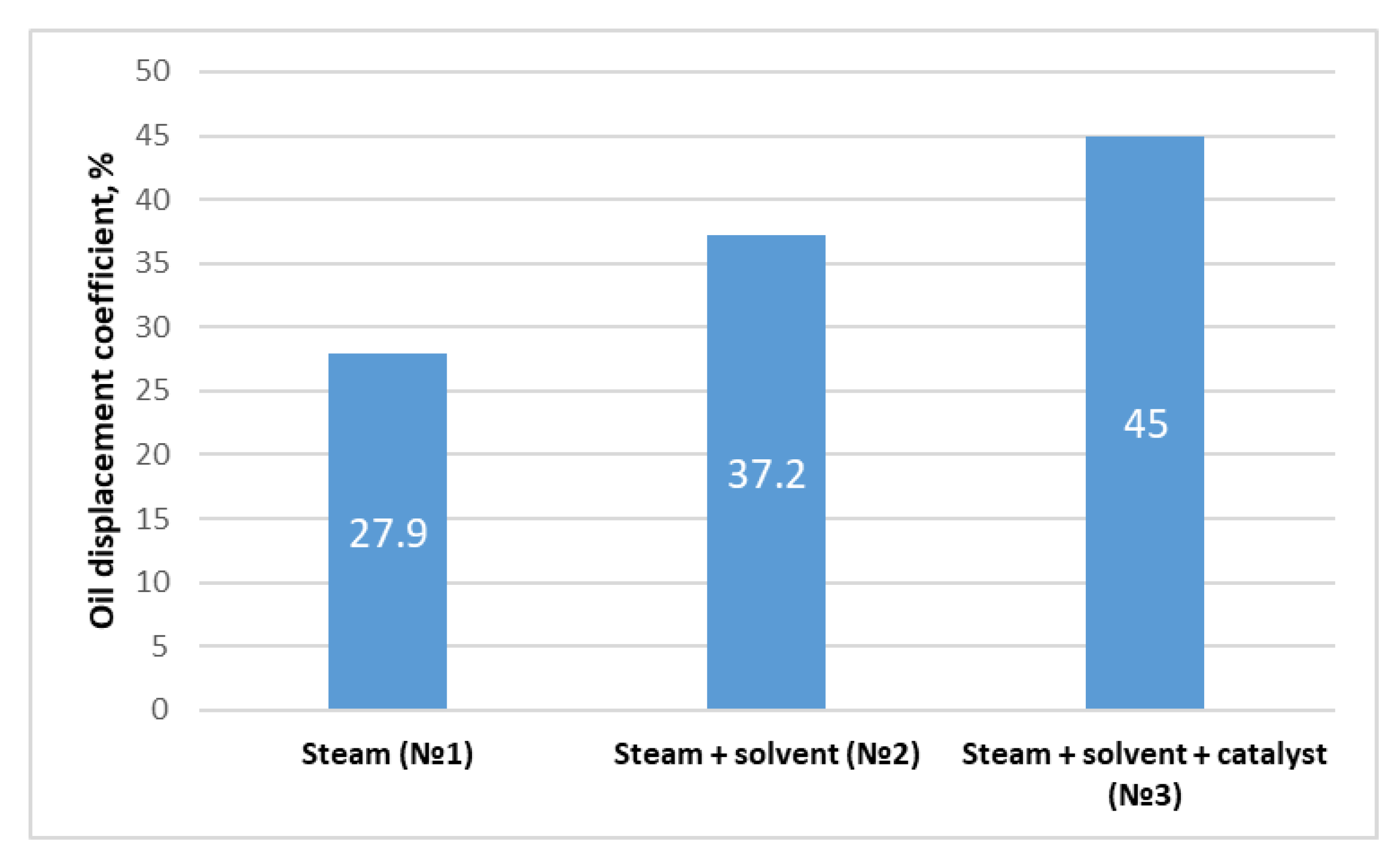
From the results of physical modeling of oil displacement coefficient determination, in the first experiment with steam injection, (T = 300 °C) oil displacement was 27.9%. The presence of a solvent increases oil displacement by 9.3% and up to 37.2%. In experiment 3, when a catalyst is added, oil displacement equaled 45%, which testifies to the increase in oil displacement efficiency by steam when using a solvent and a catalyst solution, given the increase in oil recovery by 1.3 and 1.6 times, respectively. Summary results of oil displacement coefficients are presented in Figure 4.
From the results of analysis of the group composition of displaced oil obtained by NMR, after exposure to steam with a catalyst, the content of asphaltenes in the displaced oil decreases by more than two times compared with steam injection and steam with a solvent, which indicates a thermal transformation of oil in the presence of a catalyst [29]. The results are presented in Table 1.
During the experiments, a wide range of data were obtained after thermogravimetric analysis, namely:
TG—thermogravimetric curve (mass loss curve)—a line characterizing the thermal stability of the sample.
DTG—the first derivative of the mass loss curve—a line characterizing the number of processes under thermal influence.
The results of TGA are shown in Table 2.
According to the results, we observed an increase in organic matter and the amount of coking products from the entrance to the exit of the reservoir model.
Furthermore, in each experiment, the gas phase was sampled at the fluid separation line to determine the component composition. The results are presented in Table 3.
Steam-thermal treatment (STT) at 300 °C significantly affects the increase in the gas-phase content. As can be seen from the data presented, there is a decrease in hydrogen content. Probably, the presence of the catalyst contributes to hydrogenation of double and triple bonds formed during cracking of high-molecular-weight heteroorganic compounds of heavy oil of the Boca de Jaruco field. At a temperature of 300 °C, the presence of iron thallate leads to a decrease in hydrogen sulfide content, as it participates in the formation of the sulfide form after the decomposition of the catalyst precursor [30].

3. Materials and Methods

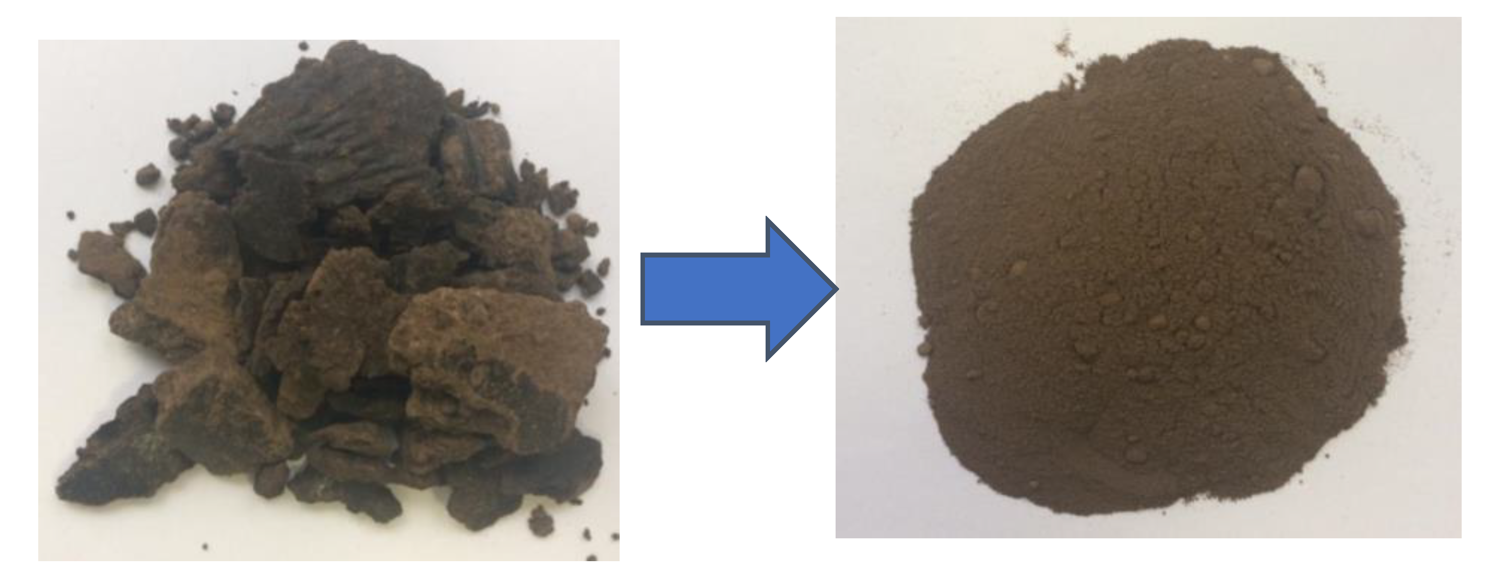
For the studies a bulk model was prepared from the initial unextracted core, which was ground to a fraction of 0.1 ÷ 1 mm (photo of samples presented in 
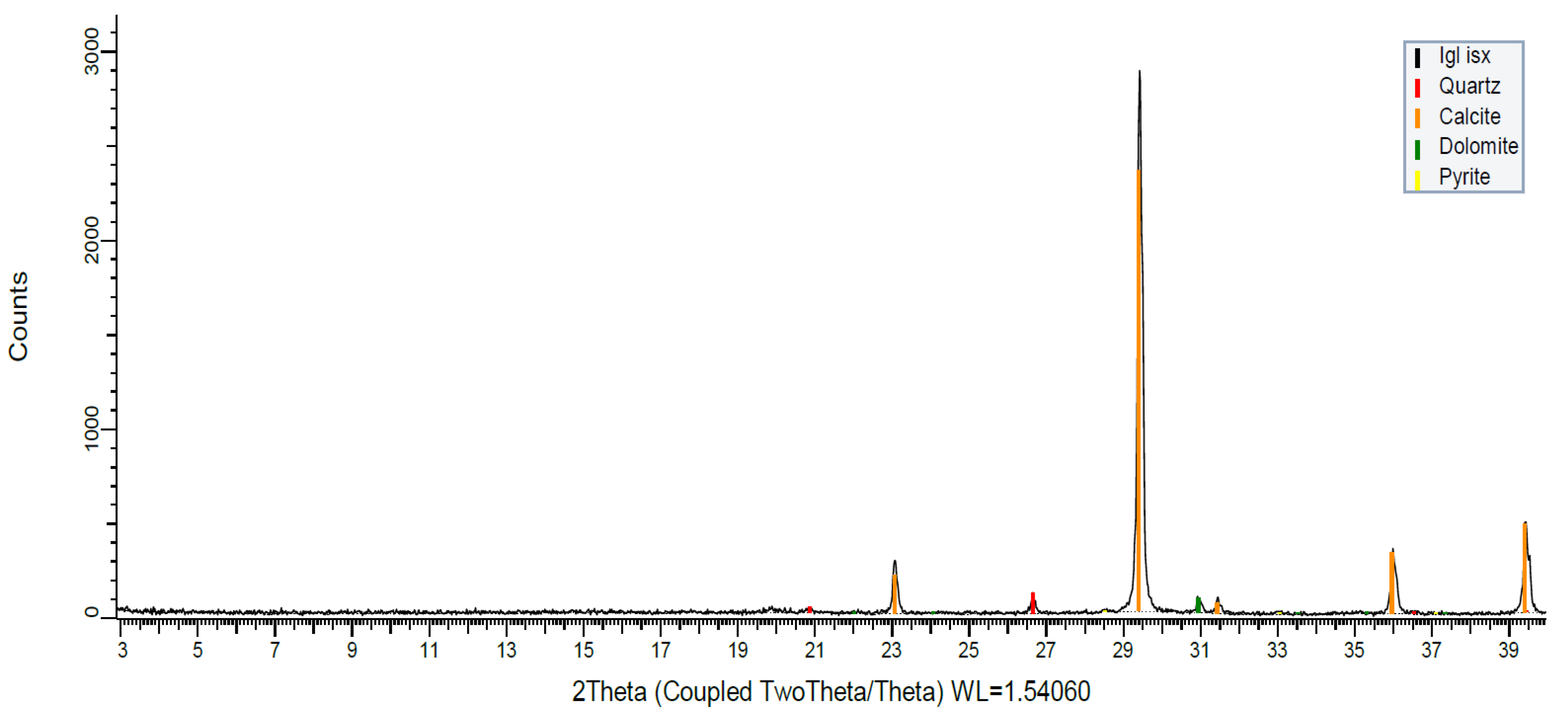
Figure 5) and mineral composition was determined by X-ray analysis (diffractogram of initial sample presented in Figure 6, results presented in Table 4) to identify the presence of clay minerals to assess complicating factors for steam injection 300 °C.
Based on the XRD results, we can see that the samples are represented by carbonates without clay minerals, which indicates that there is no risk of rock swelling during steam injection.
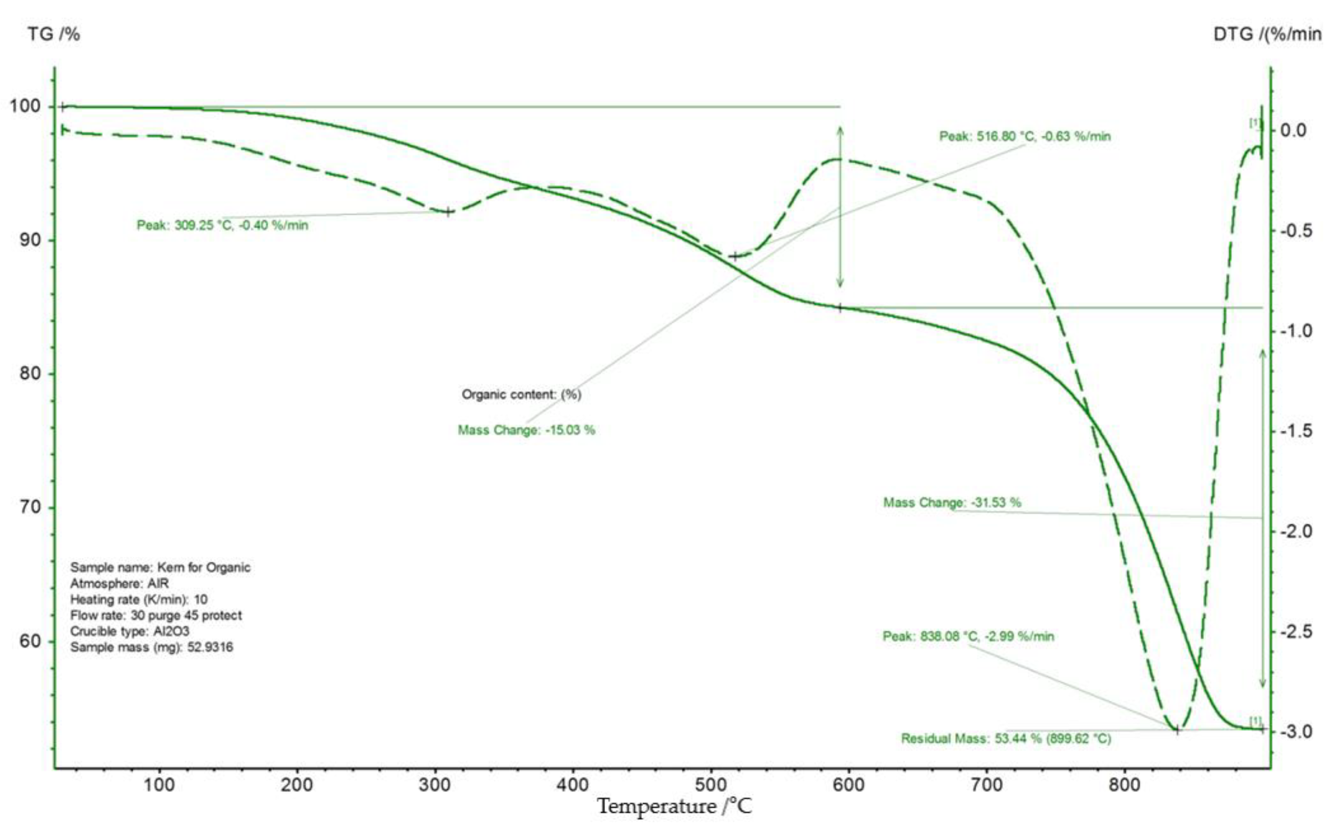
Initial oil saturation was estimated by two methods: extraction and thermogravimetric analysis (TGA) [31]. The results are shown in Figure 7.
During creation of the reservoir model, the milled unextracted rock, in all experiments, was mixed with water of a given mineralization (corresponding to the reservoir, Table 5) in a mass ratio of oil:water equal to 3:1, which corresponds to the initial oil saturation of the reservoir in question; in experiment № 2 to the prepared model was added 3 g of solvent; and in experiment №3 to the prepared model was added 6 g of catalyst solution.
In this work, a catalyst based on nickel and iron thallates was used [32]. Initially a catalyst precursor was synthesized to study its effect on oil during hydrothermal exposure. At the first stage of the catalyst manufacture, there is a synthesis of sodium salt of fatty acid by interaction of distilled tallow oil with alkali. The fatty acid saponification process can be described by the equation (using oleic acid as an example):
C17 H33 COONa + NaOH C17 H33 COONa + H2 O
The sodium salt of the fatty acid interacts with nickel and iron sulfate (NiSO4, FeSO4) when heated:
2C17 H33 CoNa + NiSO4  (C17 H33 COO)2 Ni + Na2 SO4
2C17 H33 CoNa + FeSO4  (C17 H33 COO)2 Fe + Na2 SO4
As a hydrogen donor, we chose nephras C4-155/205, which is a mixture of naphthenic and aromatic hydrocarbons. It is both a good diluent (dissolves in itself polar and nonpolar components of oil), and can also play the role of hydrogen donor, which during cracking, stops the growth of free radicals and prevents their recombination.
Model composition and experimental conditions are presented in Table 6 and Table 7. The pore volume of the model was defined as the difference between the volume of the core holder and the volumes of oil-saturated rock, reservoir water, solvent, and catalyst. Formation water is necessary to create a residual water saturation in the model corresponding to reservoir conditions. Reservoir pressure was created with nitrogen, then the model was heated to a temperature of 300 °C and kept for 24 h.
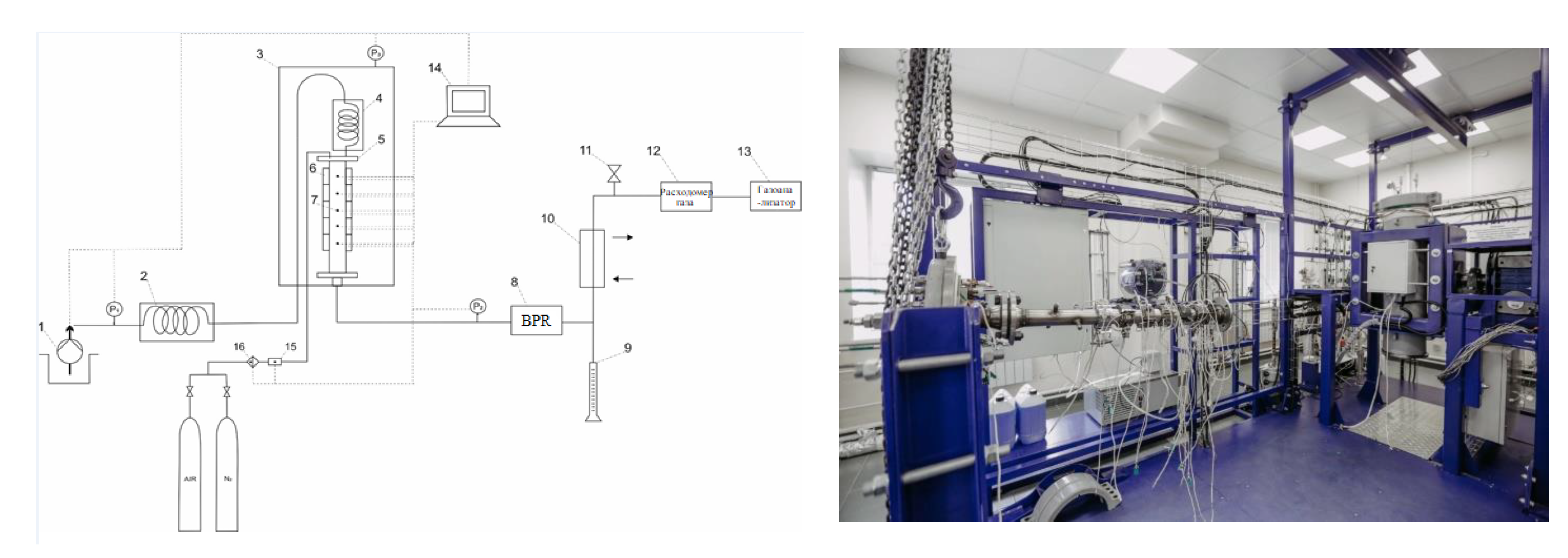
The studies were carried out on a unique scientific facility for physical and chemical modeling of in situ combustion and vapor-gravity drainage (Registration Number 2083849, Russian Federation), presented in Figure 8. A detailed description of the setup is presented in [33,34].
1—high pressure plunger pump; 2—external steam generator; 3—high pressure chamber; 4—internal steam generator; 5—core holder; 6—ceramic electric heaters; 7—thermocouples; 8—back pressure regulator; 9—separating burette; 10—refrigerator; 11—gas extraction line; 12,16—gas flowmeter; 13—gas analyzer; 14—PC; 15—gas flow regulator.
The oil displacement coefficient is calculated from the material balance using the formula:
O D C = m e . o . m i . o . · 100 %
where me.o.—mass of extracted oil, mi.o.—mass of initial oil.
The model was removed from the core sample holder for further analysis of the model distribution: organic matter content by TGA and group composition of oil by NMR on a Proton 20M NMR analyzer manufactured by CJSC special design bureau Chromatek. The method of determining the group composition of oil is described in [35].
Experiments to determine the thermal characteristics under atmospheric conditions were performed on a TG209 F1 Libra precision thermogravimeter (Netzsch GmbH) combined with an Alpha FTIR spectrometer (Bruker GmbH) in mass signal registration mode according to ASTM E2105–00 (or GOST 57988–2017). Experiments were performed in a dynamic air/nitrogen environment at a linear heating rate of 10 °C/min to 900 °C in 85 µL corundum crucibles.
The composition of inorganic and hydrocarbon gases was determined on a Chromatec Crystal 5000 chromatograph with a flame ionization detector and three thermal conductivity detectors. The sample gas was injected and distributed on three NaX 2 m, NaX 3 m, Hayesep R 3 m, and one DB-1 capillary column (Agilent J&W GC column). The flow rate of the carrier gas (helium) was 15 mL/min. The temperature of the capillary injectors is 200 °C. Temperature of capillary injector—250 °C. Temperature program of the thermostat is 5 min at 60 °C, increasing temperature to 200 °C at a rate of 10 °C/min and holding for 10 min. Chromatec Analytical 3.1 software was used to process the results.

4. Conclusions

In the present work, studies on physicochemical modeling of steam-thermal treatment of bituminous oils were carried out. Three experiments were carried out at 300 °C: steam injection, steam injection with solvent, and steam injection with solvent and catalyst. Application of the latter was aimed at additional enrichment of heavy oil, which should increase the final oil recovery. When exposed to steam at high temperatures, various transformations occur in the oil composition, such as steam reforming, formation of carbon monoxide and its further conversion into carbon dioxide and hydrogenation, methanation reactions, which finally lead to production of transformed and lightened oil with lower viscosity.
Experimental results showed that the highest oil displacement was achieved in experiment № 3 (45%), which involved a combination of solvent and steam exposure. In addition, the effect of steam and steam with the solvent on displacement coefficients was 27.9 and 37.2%, respectively. As a result of the study, a deeper conversion of resinous–asphaltene compounds of oil due to their destruction and separation of alkyl substituents is established, resulting in an increase in the content of the fraction of saturated hydrocarbons. Additionally, the SARA analysis of the displaced oil in experiment № 3 confirms an increase in the fraction of saturated and aromatic hydrocarbons and a decrease in the asphaltenes fraction by over 10.9%, compared to the initial oil. This demonstrates the effectiveness of using steam and aquathermolysis catalyst solution in combination in terms of extracting extra-viscous oil.

Author Contributions

Conceptualization, I.F.M.; data curation, V.V.C., S.I.K. and I.S.A.; investigation, A.R.T., V.V.C., A.V.S., I.I.M. and S.A.S., G.V.S.; methodology, I.F.M., A.V.B. and D.A.A.; project administration, M.A.V., K.A.D.; supervision, A.V.V.; validation, S.A.S. and I.O.S.; visualization, I.I.M.; writing—original draft, I.F.M.; writing—review and editing, M.A.V. All authors have read and agreed to the published version of the manuscript.

Funding

The work is carried out under the support of the Russian Science Foundation related to the Project № 21-73-30023 dated 17.03.2021.

Conflicts of Interest

The authors declare no conflict of interest.

References

  1. Pituganova, A.; Nassan, T.; Amro, M.; Minkhanov, I.; Varfolomeev, M.; Bolotov, A. Experimental and Numerical Analysis of Thermal EOR Recovery Schemes for Extra-Heavy Oil of the Oykino-Altuninsky Uplift of the Romashkinskoye Oilfield. In Proceedings of the International Petroleum Technology Conference, Riyadh, Saudi Arabia, 21–23 February 2022; OnePetro: Richardson, TX, USA, 2022. [Google Scholar]
  2. Pituganova, A.; Minkhanov, I.; Bolotov, A.; Varfolomeev, M. Screening of waterflooding, hot waterflooding and steam injection for extra heavy crude oil production from Tatarstan oilfield. In IOP Conference Series: Earth and Environmental Science; IOP Publishing: Bristol, UK, 2021; Volume 931, p. 12002. [Google Scholar]
  3. Muraza, O.; Galadima, A. Aquathermolysis of heavy oil: A review and perspective on catalyst development. Fuel 2015, 157, 219–231. [Google Scholar] [CrossRef]
  4. Li, F.; Wang, X.; Pan, H.; Li, Q.; Yang, J. Preparation of disk-like α-Fe2O3 nanoparticles and their catalytic effect on extra heavy crude oil upgrading. Fuel 2019, 251, 644–650. [Google Scholar] [CrossRef]
  5. Mukhamatdinov, I.I.; Salih, I.S.S.; Vakhin, A.V. Changes in the subfractional composition of heavy oil asphaltenes under aquathermolysis with oil-soluble Co-based catalyst. Pet. Sci. Technol. 2019, 37, 1589–1595. [Google Scholar] [CrossRef]
  6. Altunina, L.K.; Kuvshinov, V.A.; Kuvshinov, I.V.; Chertenkov, M.V.; Ursegov, S.O. Pilot tests of new EOR technologies for heavy oil reservoirs. In Proceedings of the SPE Russian Petroleum Technology Conference, Moscow, Russia, 26–28 October 2015; OnePetro: Richardson, TX, USA, 2015. [Google Scholar]
  7. Mukhamatdinov, I.I.; Khaidarova, A.R.; Mukhamatdinova, R.E.; Affane, B.; Vakhin, A.V. Development of a catalyst based on mixed iron oxides for intensification the production of heavy hydrocarbon feedstocks. Fuel 2022, 312, 123005. [Google Scholar] [CrossRef]
  8. Mukhamatdinov, I.I.; Vakhin, A.V.; Sitnov, S.A.; Khaidarova, A.R.; Zaripova, R.D.; Garifullina, E.I.; Katnov, V.E.; Stepin, S.N. Intraformation Transformation of Heavy Oil by Mixed Fe (II, III) Oxides. Chem. Technol. Fuels Oils 2018, 54, 412–423. [Google Scholar] [CrossRef]
  9. Vakhin, A.V.; Aliev, F.A.; Mukhamatdinov, I.I.; Sitnov, S.A.; Kudryashov, S.I.; Afanasiev, I.S.; Petrashov, O.V.; Nurgaliev, D.K. Extra-heavy oil aquathermolysis using nickel-based catalyst: Some aspects of in-situ transformation of catalyst precursor. Catalysts 2021, 11, 189. [Google Scholar] [CrossRef]
  10. Alaei, M.; Bazmi, M.; Rashidi, A.; Rahimi, A. Heavy crude oil upgrading using homogenous nanocatalyst. J. Pet. Sci. Eng. 2017, 158, 47–55. [Google Scholar] [CrossRef]
  11. Li, G.-R.; Chen, Y.; An, Y.; Chen, Y.-L. Catalytic aquathermolysis of super-heavy oil: Cleavage of CS bonds and separation of light organosulfurs. Fuel Process. Technol. 2016, 153, 94–100. [Google Scholar] [CrossRef]
  12. Leaute, R.P. Liquid addition to steam for enhancing recovery (LASER) of bitumen with CSS: Evolution of technology from research concept to a field pilot at Cold Lake. In Proceedings of the SPE International Thermal Operations and Heavy Oil Symposium and International Horizontal Well Technology Conference, Calgary, AB, Canada, 4–7 November 2002; OnePetro: Richardson, TX, USA, 2002. [Google Scholar]
  13. Minkhanov, I.F.; Bolotov, A.V.; Al-Muntaser, A.A.; Mukhamatdinov, I.I.; Vakhin, A.V.; Varfolomeev, M.A.; Slavkina, O.V.; Shchekoldin, K.A.; Darishchev, V.I. Experimental study on the improving the efficiency of oil displacement by co-using of the steam-solvent catalyst (Russian). Neft. Khozyaystvo-Oil Ind. 2021, 2021, 54–57. [Google Scholar] [CrossRef]
  14. Pathak, V.; Babadagli, T.; Edmunds, N.R. Heavy oil and bitumen recovery by hot solvent injection. J. Pet. Sci. Eng. 2011, 78, 637–645. [Google Scholar] [CrossRef]
  15. Minkhanov, I.F.; Bolotov, A.V.; Sagirov, R.N.; Varfolomeev, M.A.; Anikin, O.V.; Tazeev, A.R.; Derevyanko, V.K. The Influence of the Content of Clay Minerals on the Efficiency of Steam Treatment Injection for the Bitumen Oils Recovery. SOCAR Proc. 2021, 2, 65–75. [Google Scholar] [CrossRef]
  16. Kaczmarczyk, R.; Gurgul, S. A thermodynamic analysis of heavy hydrocarbons reforming for solid oxide fuel cell application as a part of hybrid energy systems. Energies 2021, 14, 337. [Google Scholar] [CrossRef]
  17. Kadiev, K.M.; Oknina, N.V.; Gyul’Maliev, A.M.; Gagarin, S.G.; Kadieva, M.K.; Batov, A.E.; Khadzhiev, S.N. On the mechanism and main features of hydroconversion of the organic matter of oil sludge in the presence of nanosized catalysts. Pet. Chem. 2015, 55, 563–570. [Google Scholar] [CrossRef]
  18. Morelos-Santos, O.; de la Torre, A.I.R.; Schacht-Hernández, P.; Portales-Martínez, B.; Soto-Escalante, I.; Mendoza-Martínez, A.M.; Mendoza-Cruz, R.; Velázquez-Salazar, J.J.; José-Yacamán, M. NiFe2O4 nanocatalyst for heavy crude oil upgrading in low hydrogen/feedstock ratio. Catal. Today 2021, 360, 20–26. [Google Scholar] [CrossRef]
  19. Sviridenko, N.N.; Urazov, K.K. Catalytic upgrading of heavy oil from the Ashalchinskoye oilfield. Pet. Sci. Technol. 2022, 1–16. [Google Scholar] [CrossRef]
  20. Sviridenko, N.N.; Akimov, A.S. Effect of pre-oxidation of dispersed catalysts on heavy oil cracking. Pet. Sci. Technol. 2022, 1–15. [Google Scholar] [CrossRef]
  21. Urazov, K.; Sviridenko, N.N. Structural Transformations of Heavy Oil Asphaltenes from the Zyuzeevskoye Field upon Thermocatalytic Cracking. Solid Fuel Chem. 2022, 56, 128–132. [Google Scholar] [CrossRef]
  22. Urazov, K.K.; Sviridenko, N.N. NiO based catalysts obtained “in-situ” for heavy crude oil upgrading: Effect of NiO precursor on the catalytic cracking products composition. J. Taiwan Inst. Chem. Eng. 2021, 127, 151–156. [Google Scholar] [CrossRef]
  23. Pevneva, G.S.; Voronetskaya, N.G.; Sviridenko, N.N.; Golovko, A.K. Effect of WC/Ni–Cr additive on changes in the composition of an atmospheric residue in the course of cracking. Pet. Sci. 2020, 17, 499–508. [Google Scholar] [CrossRef] [Green Version]
  24. Mukhamatdinov, I.I.; Salih, I.S.S.; Rakhmatullin, I.Z.; Sviridenko, N.N.; Pevneva, G.S.; Sharma, R.K.; Vakhin, A. V Transformation of Resinous Components of the Ashalcha Field Oil during Catalytic Aquathermolysis in the Presence of a Cobalt-Containing Catalyst Precursor. Catalysts 2021, 11, 745. [Google Scholar] [CrossRef]
  25. Sviridenko, N.N.; Krivtsov, E.B.; Golovko, A.K. Destruction of resins and asphaltenes of natural bitumen on a nickel-containing catalyst. Chem. Sustain. Dev. 2017, 25, 79–84. [Google Scholar]
  26. Ma, L.; Slaný, M.; Guo, R.; Du, W.; Li, Y.; Chen, G. Study on synergistic catalysis of ex-situ catalyst and in-situ clay in aquathermolysis of water-heavy oil-ethanol at low temperature. Chem. Eng. J. 2023, 453, 139872. [Google Scholar] [CrossRef]
  27. Maity, S.K.; Ancheyta, J.; Marroquín, G. Catalytic Aquathermolysis Used for Viscosity Reduction of Heavy Crude Oils: A Review. Energy Fuels 2010, 24, 2809–2816. [Google Scholar] [CrossRef]
  28. Vakhin, A.V.; Mukhamatdinov, I.I.; Aliev, F.A.; Feoktistov, D.A.; Sitnov, S.A.; Gafurov, M.R.; Minkhanov, I.F.; Varfolomeev, M.A.; Nurgaliev, D.K.; Simakov, I.O.; et al. Industrial application of nickel tallate catalyst during cyclic steam stimulation in Boca De Jaruco Reservoir. In Proceedings of the Russian Petroleum Technology Conference 2021, RPTC 2021, Virtual, 12–15 October 2021. [Google Scholar] [CrossRef]
  29. Adeniyi, A.G.; Ighalo, J.O. Hydrogen production by the steam reforming of waste lubricating oil. Indian Chem. Eng. 2019, 61, 403–414. [Google Scholar] [CrossRef]
  30. Ibrahim, A.A.; Eyvaz, M. Hydrogen production from light hydrocarbons. In Advances in Hydrogen Generation Technologies; IntechOpen: London, UK, 2018. [Google Scholar]
  31. Mikhailova, A.N.; Kayukova, G.P.; Varfolomeev, M.A.; Emelyanov, D.A. Thermogravimetric parameters of the oxidation of organic matter and asphaltenes from the rocks of the Permian deposits of heavy oil field before and after catalytic hydrothermal treatment. Fuel 2022, 313, 122641. [Google Scholar] [CrossRef]
  32. Vakhin, A.V.; Mukhamatdinov, I.I.; Sitnov, S.A.; Mukhamatdinova, R.E.; Simakov, I.O.; Nikitina, E.A.; Solovev, A.V.; Sansiev, G.V.; Dubrovin, K.A.; Sharifullin, A.V. Catalytic Activity of Nickel and Iron Sulfides in the Degradation of Resins and Asphaltenes of High-Viscosity Oil in the Presence of Carbonate Rock under Hydrothermal Conditions. Kinet. Catal. 2022, 63, 569–576. [Google Scholar] [CrossRef]
  33. Anikin, O.V.; Bolotov, A.V.; Minkhanov, I.F.; Varfolomeev, M.A.; Tazeev, A.R.; Chalin, V.V.; Lutfullin, A.A.; Abusalimov, E.M. Factors influencing hydrogen peroxide decomposition dynamics for thermochemical treatment of bottomhole zone. J. Pet. Explor. Prod. Technol. 2022, 12, 2587–2598. [Google Scholar] [CrossRef]
  34. Minkhanov, I.F.; Bolotov, A.V.; Tazeev, A.R.; Chalin, V.V.; Kacou, A.F.D.; Galeev, R.I.; Sagirov, R.N.; Al-Muntaser, A.A.; Emelianov, D.A.; Khelkhal, M.A.; et al. The Influence of Reservoir Clay Composition on Heavy Oil in situ Combustion. Processes 2022, 10, 2308. [Google Scholar] [CrossRef]
  35. Volkov, V.Y.; Al-Muntaser, A.A.; Varfolomeev, M.A.; Khasanova, N.M.; Sakharov, B.V.; Suwaid, M.A.; Djimasbe, R.; Galeev, R.I.; Nurgaliev, D.K. Low-field NMR-relaxometry as fast and simple technique for in-situ determination of SARA-composition of crude oils. J. Pet. Sci. Eng. 2021, 196, 107990. [Google Scholar] [CrossRef]
Figure 1. Pressure drop and oil displacement coefficient in experiment № 1.
Catalysts 13 00283 g001
Figure 2. Pressure drop and oil displacement coefficient in experiment № 2.
Catalysts 13 00283 g002
Figure 3. Pressure drop and oil displacement coefficient in experiment № 3.
Catalysts 13 00283 g003
Figure 4. Distribution of oil displacement coefficients by experiments.
Catalysts 13 00283 g004
Figure 5. Initial and milled to a fraction of 0.1 ÷ 1 mm core material.
Catalysts 13 00283 g005
Figure 6. Diffractogram of the original core sample.
Catalysts 13 00283 g006
Figure 7. Thermogram of the original sample.
Catalysts 13 00283 g007
Figure 8. Schematic and photo of a unique scientific facility for physical and chemical modeling of the process of in-situ combustion and steam-gravity drainage.
Catalysts 13 00283 g008
Table 1. Changes in the group composition of oil.
SampleAsphaltenes, %Resins, %Saturated and Aromatic HC, %
Initial oil23.60 ± 0.0233.90 ± 0.0742.50 ± 0.03
Displaced oil 1 26.13 ± 0.0334.86 ± 0.0239.01 ± 0.02
Displaced oil 223.55 ± 0.0343.70 ± 0.0232.75 ± 0.05
Displaced oil 312.69 ± 0.0543.17 ± 0.0444.14 ± 0.04
Table 2. The content of organic matter and coke after experiments.
ExperimentContent, %Zone 1Zone 2Zone 3Zone 4
1Organic matter8 ± 0.0210 ± 0.0912 ± 0.0714 ± 0.01
Coking products0.58 ± 0.030.59 ± 0.020.63 ± 0.061.8 ± 0.03
2Organic matter8.28 ± 0.029.90 ± 0.0712.02 ± 0.0811.25 ± 0.09
Coking products0.65 ± 0.050.78 ± 0.060.52 ± 0.020.88 ± 0.03
3Organic matter6.31 ± 0.086.33 ± 0.048.95 ± 0.0313.34 ± 0.11
Coking products0.32 ± 0.010.20 ± 0.100.58 ± 0.041.15 ± 0.02
Table 3. Component composition of gas at the fluid separation line in the experiments (mol %).
ComponentExperiment № 1Experiment № 2Experiment № 3
Pore Volume
1234123456123456
Hydrogen14.8912.7713.3512.922.943.094.453.053.534.025.875.565.315.925.216.07
Carbon dioxide52.2665.8564.0663.1327.6925.3129.9123.3622.8517.1568.3168.6068.7265.7763.8060.12
Methane4.564.755.795.6915.4617.1923.4519.0122.1924.363.353.573.914.194.155.95
Ethan1.441.251.651.593.934.464.955.356.177.050.820.830.991.071.121.85
Propane1.880.921.341.313.563.663.484.585.216.0812.1813.0613.4613.7016.2614.70
Hydrogen sulfide2.0411.0810.8912.343.142.924.024.013.910.130.670.660.840.901.011.77
Iso-Butane0.300.090.140.140.290.280.270.390.470.590.040.040.060.060.080.14
Butane1.550.470.730.742.102.372.003.013.333.850.430.410.530.550.690.93
Iso-Pentane1.730.190.150.171.201.070.781.111.101.370.090.090.110.130.140.26
Pentane0.670.220.240.261.841.821.331.921.912.350.220.210.320.320.430.61
Hexane17.682.221.431.4324.1725.2216.6422.6919.4223.590.000.000.000.000.000.00
Heptane0.580.110.140.1612.4512.038.4411.189.599.474.273.933.123.523.613.59
Octane0.370.070.100.141.210.570.280.340.340.000.140.150.060.090.110.54
Nonan0.070.020.000.000.000.000.000.000.000.000.000.000.000.000.000.00
CO0.000.000.000.000.000.000.000.000.000.003.612.902.583.793.393.46
Amount100100100100100100100100100100100100100100100100
Table 4. Mineral composition of the rock.
MineralMass Content, %
Calcite92 ± 0.08
Pyrite1 ± 0.10
Dolomite4 ± 0.04
Quartz3 ± 0.03
Table 5. Component composition of produced water.
Component, mg/LTotal MineralizationDensity, kg/m3
CO32−HCO3SO42−ClCa2+Mg2+Na+ + K+
0292.851119.477780.54436.519.635174.2114,913.211007.58
Table 6. Composition of the model of experiments.
InjectantMrock, gSOI, % *SOI, % **moil in the Model, g *Mass of Formation Water in the Model, gMass of Solvent, Catalyst + Solvent, g
1Steam10001515.0315050-
2Steam/solvent3
3Steam/solvent + catalyst6
* Initial oil saturation by extraction method, ** Initial oil saturation by TGA method.
Table 7. Conditions of experiments.
Temperature, °CPorosity, %Pore Volume, mLPermeability, DReservoir Pressure, MPaWater Injection Rate, mL/min
130037187.21.691.85
237.5189.7
337.9191.7
Disclaimer/Publisher’s Note: The statements, opinions and data contained in all publications are solely those of the individual author(s) and contributor(s) and not of MDPI and/or the editor(s). MDPI and/or the editor(s) disclaim responsibility for any injury to people or property resulting from any ideas, methods, instructions or products referred to in the content.

