Article

Microwave-Assisted CO Oxidation over Perovskites as a Model Reaction for Exhaust Aftertreatment—A Critical Assessment of Opportunities and Challenges

1
Institute of Inorganic Chemistry, RWTH Aachen University, Landoltweg 1a, 52074 Aachen, Germany
2
Center for Automotive Catalytic Systems Aachen, RWTH Aachen University, 52062 Aachen, Germany
*
Author to whom correspondence should be addressed.
Catalysts 2022, 12(7), 802; https://doi.org/10.3390/catal12070802
Submission received: 24 June 2022 / Revised: 18 July 2022 / Accepted: 19 July 2022 / Published: 21 July 2022
(This article belongs to the Special Issue Catalysis by Unconventional Heating)

Abstract

:
We introduce a microwave (MW)-assisted heterogeneous catalytical setup, which we carefully examined for its thermal and performance characteristics. Although MW-assisted heterogeneous catalysis has been widely explored in the past, there is still need for attention towards the specific experimental details, which may complicate the interpretation of results and comparability in general. In this study we discuss technical and material related factors influencing the obtained data from MW-assisted heterogeneous catalysis, specifically in regards to the oxidation of carbon monoxide over a selected perovskite catalyst, which shall serve as a model reaction for exhaust gas aftertreatment. A high degree of comparability between different experiments, both in terms of setup and the catalysts, is necessary to draw conclusions regarding this promising technology. Despite significant interest from both fundamental and applied research, many questions and controversies still remain and are discussed in this study. A series of deciding parameters is presented and the influence on the data is discussed. To control these parameters is both a challenge but also an opportunity to gain advanced insight into MW-assisted catalysis and to develop new materials and processes. The results and discussion are based upon experiments conducted in a monomode MW-assisted catalysis system employing powdered solid-state perovskite oxides in a fixed bed reactor. The discussion covers critical aspects concerning the determination of the actual catalyst temperature, the homogeneity of the thermal distribution, time, and local temperature relaxation (i.e., thermal runaway effects and hotspot formation), particle size effects, gas flow considerations, and system design.

1. Introduction

Within the framework of the Cluster of Excellence “The Fuel Science Center” at RWTH Aachen University, we investigate the production and application of fuels from bio-based carbon feedstocks, CO2 and H2, and their use in advanced combustion processes [1,2]. Within this cluster, particular interest is placed upon the development of novel catalysts and processes for an adaptive exhaust gas aftertreatment for the removal of carbon monoxide (CO), hydrocarbon, and oxygenated hydrocarbon compounds and nitric oxides. One focus in this context is the utilization of a microwave (MW) catalytical test setup for the quick and efficient screening of promising oxidation catalysts and the development of MW-assisted catalysis process conditions.
MW assisted reactions have attracted much attention for various types of chemical synthesis [3,4,5,6]. In recent years, an increasing number of applications have been developed using microwaves to heat and activate solid materials for direct heterogeneous catalysis, as it holds promise to allow higher energy efficiency based on renewably energy [6,7,8,9]. The efficacy of the MW-assisted catalysis is in many cases found to be directly dependent on the ability of the solid catalysts to absorb and dissipate the energy carried by the microwaves and can be expressed in form of the material specific MW susceptibility [6,7]. Additionally, many organic compounds and biomass in particular were found to be susceptible to MW-activation, which opens up the possibility of technically relevant industrial applications [10].
The interaction of MW with the chemical reaction setup is based upon dipolar polarization and relaxation phenomena, as well as several magnetic and electronic effects, which can all contribute to the heating effect of materials and surfaces [11]. The heating itself may lead to localized energy accumulation (i.e., hotspot formation), which can greatly affect catalytic reactions by opening up new reaction paths beyond the conventional thermal excitation of both, catalysts and reactants. While the dielectric permittivity behavior constitutes the dominating loss mechanism for many materials, magnetic and electronic factors can play a significant role in certain compounds as well. Among these, complex perovskite oxides with mixed 3d-element sublattices lead to particular high activities in several heterogeneous catalytic reactions [12]. The dielectric polarization is of a complex nature and may be divided into several loss processes, which include induced dipolar moments in the bulk crystal and polarization of interfaces. Complicating the fundamental picture further is the different thermal dependencies of dielectric, electronic, and magnetic properties which result in a hard to predict response of the MW-heating process in technical catalyst materials [13]. Here, we want to point out that a deep fundamental mechanistic discussion of the MW-matter interaction is beyond the scope of this work, as this would include the ongoing discussion about the dominating effects behind MW-activated catalysis, namely thermal vs. non-thermal effects [14,15]. We refer the interested reader to the references cited above.
In this study we report on our results from the operation of a MW-assisted catalysis setup. MW-heterogeneous gas-phase catalysis experiments have been reported both in monomode and multimode configurations, a distinction that refers to different concepts of MW-generation and guidance towards the catalyst [9,16,17]. In a multimode system, a multitude of waves is generated and guided towards a cavity where reflection and interference of those waves at the walls leads to a complex, non-uniform field distribution which generally is difficult to control. In contrast, monomode MW-systems rely on the generation of a standing wave, which can be guided very precisely towards the catalyst and yield optimum field strength and homogeneity at the point of interest. While the multimode generation is relatively cheap and easy to realize, the monomode configuration is more suited to studying fundamental MW-matter interaction and catalysis and can also lead to more energy efficient heating. We therefore focus our work on a monomode catalyst testing system.
In order to evaluate our MW-assisted catalysis setup and to discuss important technical aspects of MW-catalysis, we selected the CO oxidation over La0.8Sr0.2CoO3 (LSC-82) perovskite oxide powders, a well-known model-reaction with a highly active catalyst as was demonstrated before, to ensure a broad perception and usability of our results [18]. This particularly holds for exhaust gas aftertreatment in combustion processes, which have been studied extensively before, both by means of convectional heating and MW-activation [19,20]. Perovskite oxides are highly active oxidation catalysts that can rival the performance of noble metals with a high degree of tuneability as the crystal structure is known for its ability to tolerate a large extent of cationic substitution and structural defects [12]. Interestingly, this feature also increases their applicability in MW-assisted processes, as mixed substitution with 3d-elements like Fe, Co, Ni, or Cu and the associated defect generation can lead to drastic changes in the electronic and magnetic properties, which in turn affects the MW-susceptibility of the material [21,22].
Some of the scientific and technical aspects result in challenges during the data acquisition for MW-assisted catalysis. Particularly the thermal sensing has been identified as major contributor and was discussed in the literature [8,9,10,23,24,25]. This study therefore covers in detail the determination of the actual catalyst temperature, the temperature non-uniformity within the reactor, and the implications of steep thermal gradients on the results, comparative data of MW-assisted CO oxidation under varying process conditions and MW-specific effects on the catalyst material.

2. Results and Discussion

2.1. Homogeneity of the Thermal Distribution and Temperature Sensing

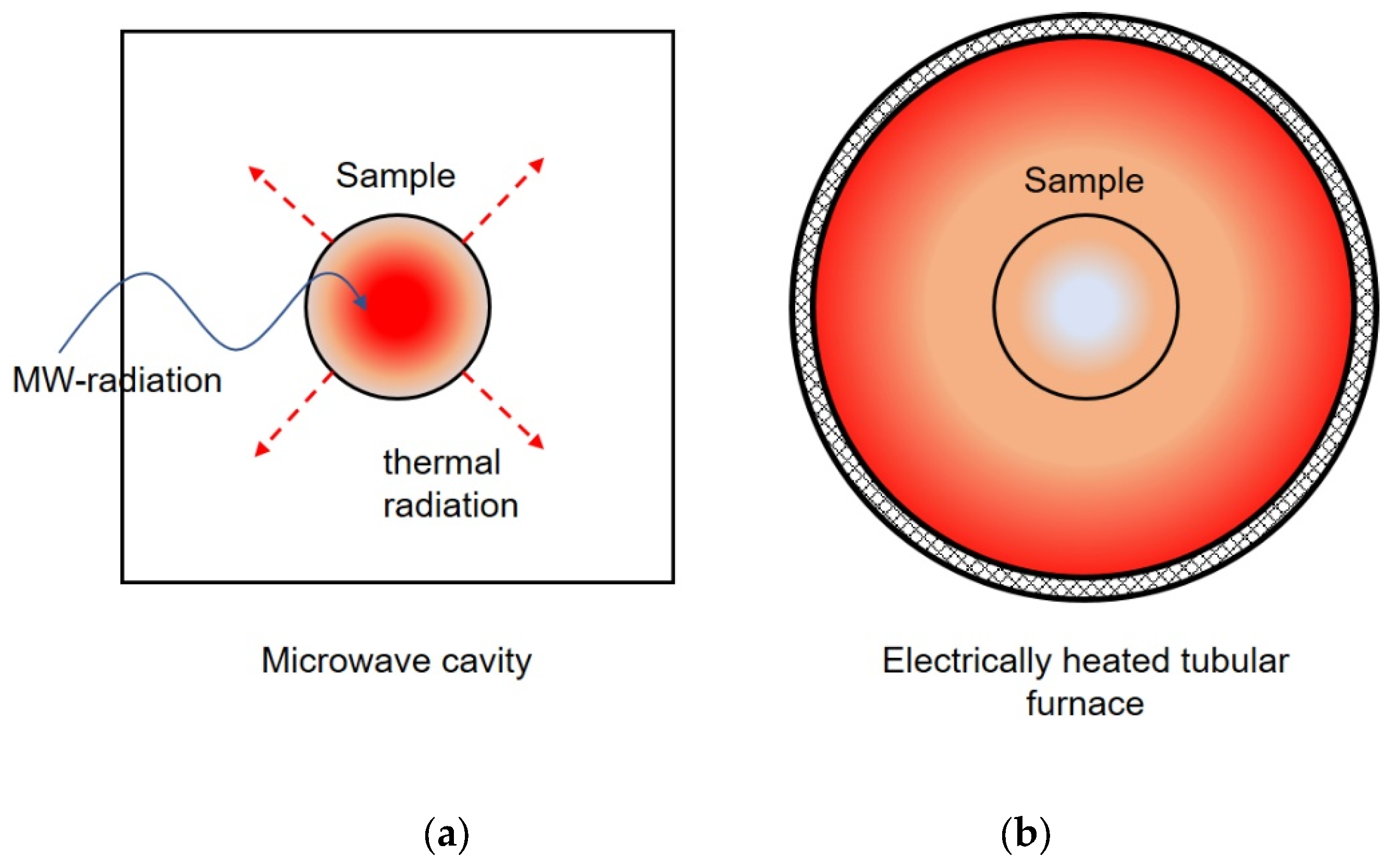
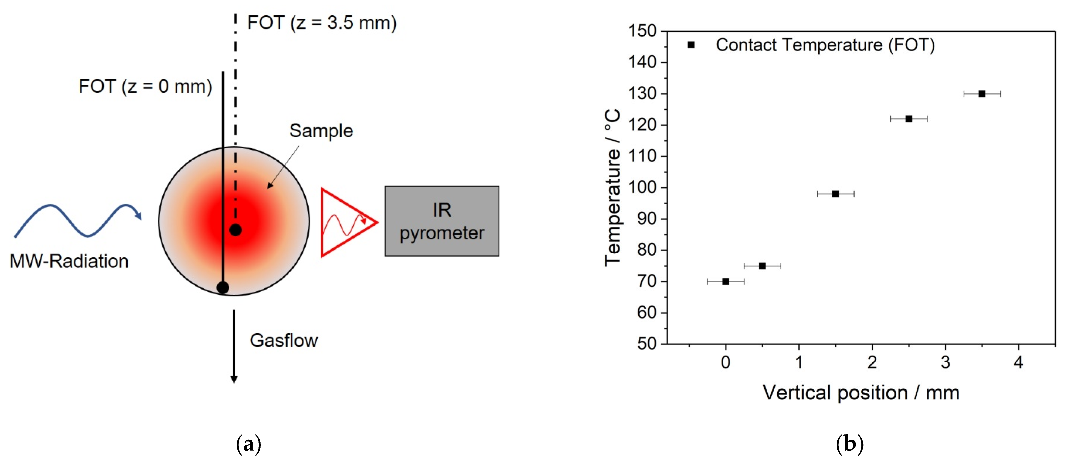
2.1.1. Thermal Gradients

When conducting catalysis research, i.e., quantifying the catalytic performance of materials as a function of temperature, understanding kinetics and mechanistical aspects, it is desirable to have a macroscopically homogeneous temperature distribution within the catalyst bed. However, in real-life systems this is often not the case [24,25]. The extent to which a temperature gradient across the catalyst bed forms and the shape of this gradient are dependent on both material properties and the setup. Due to the physical nature of the interaction, in MW-assisted catalytic setups the gradient forms with higher temperatures in the inside and lower temperatures at the outside of the catalyst bed, which is in contact with a not directly heated reactor wall—the exact opposite of the situation in a conventional conductively heated system, which is typically heated from the outside to the inside and shows much shallower thermal gradients under steady-state conditions. This fact has been described by Will et al., before and is schematically shown in Figure 1 [21]. In the case of the MW-heated catalyst, the surrounding of the heated solid remains relatively cool, as the energy is taken up by the catalyst itself. This situation, i.e., a hot catalyst surface and cool gaseous reactants, may lead to significant changes in selectivity and kinetics in comparison to the conventional, convective heating, where catalyst and gaseous reactants have very similar temperatures [6].
In order to evaluate the thermal profile of the catalyst bed in response to exposure of MW-radiation, we conducted experiments where we controlled the applied MW-power as such that the IR-pyrometer showed a constant value of 70 °C and measured the contact temperature in different positions inside the catalyst bed by use of the fiberoptic thermal sensor (FOT) (see Figure 2a). It has to be noted that for this experiment no emissivity calibration was conducted, as it would result in a faulty representation of the gradient. Instead, we chose a value of 0.8, approximated from literature resources of this material family [26,27]. In this way we found that in general, even at relatively low temperatures and considering the small spherical reactor volume (⌀ = 9.5 mm), there was a pronounced temperature gradient recorded. For the LSC-82 sample this gradient amounted to approximately 60 °C between inside and outside, which is shown in Figure 2b. This finding is consistent with previous findings in literature [9].
While the origin of this gradient can be assumed to lie in the direct nature of the radiative MW-heating, the reactor design, process conditions, and material parameters (i.e., particle size, MW-susceptibility) will determine its slope. Unfortunately, the scenario depicted in Figure 2 leads to a fundamental difficulty in describing and comparing the results of catalytical testing from MW-assisted systems, as the temperature during the catalysis is arguably the most important parameter, and both precise determination as well as homogeneous conditions across the entire reaction zone are necessary. Considering this, a thorough characterization of thermal gradients and suitable thermal sensing methods is necessary before concluding the catalytic testing results. Both adequate reactor design and optimized process conditions may help to minimize the extent of gradients, which is a prerequisite for the comparability of catalytic characterizations between different materials and heating methods, i.e., the widely conducted comparison between MW-assisted catalysis and conventionally heated systems.

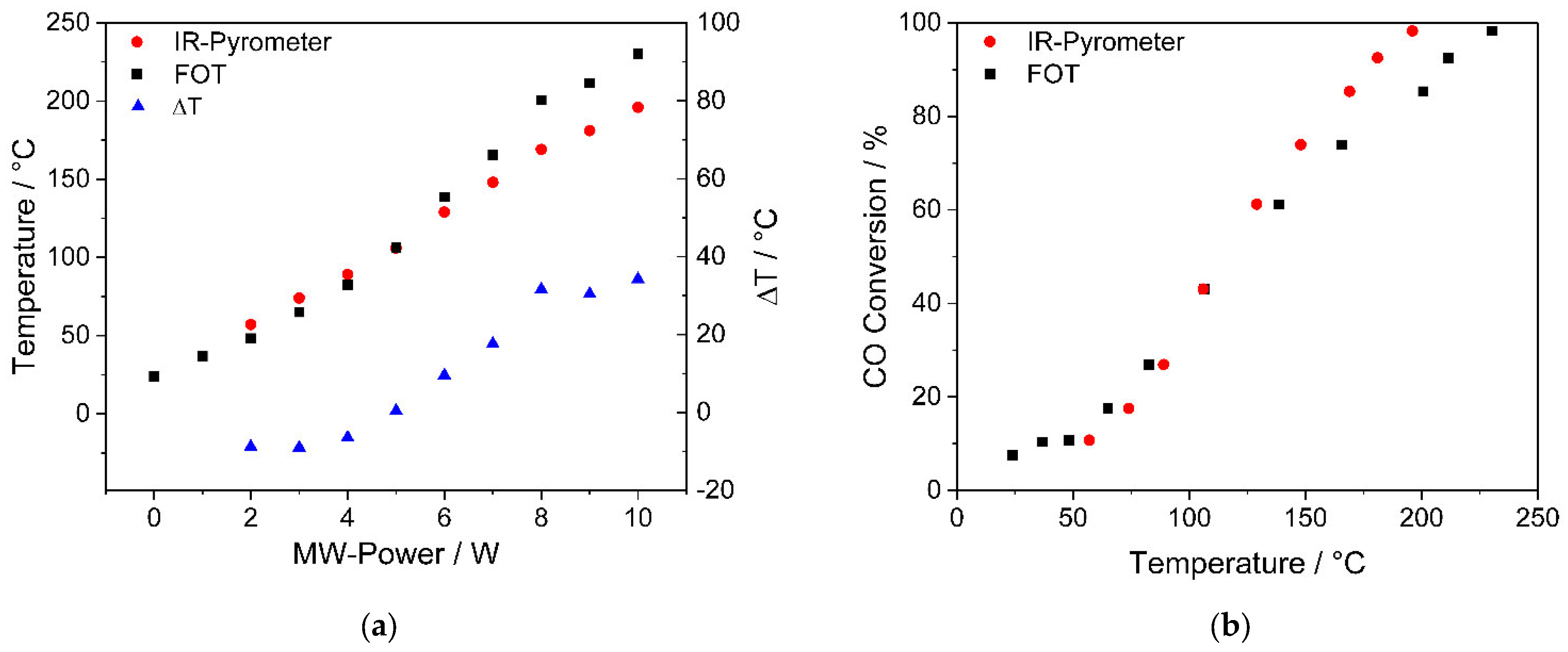
2.1.2. Thermal Sensing

As indicated above, the determination of the true temperature of the catalyst is of prime importance for the assessment of the chemical properties, kinetic analyses, and the comparability of the results. While this statement may seem trivial at first, certain factors complicate this issue in the case of MW-activated catalysis systems. Widely utilized IR-pyrometric sensing tools will determine the temperature of the outside region of the catalyst bed, while the inside may, as indicated above, exhibit strongly different conditions (see Figure 1 and Figure 2). In addition, IR-pyrometers need to be carefully calibrated to the target material by adjusting the emissivity factor ε [28] (see Equation (1)), usually in combination with a contact thermal sensor or thermocouple.
Pyrometers operate by sensing thermal radiation which can be described by Planck’s blackbody radiation law, which has to be amended by Kirchhoff’s law (see Equation (2)) to consider material specific properties in terms of emissivity ε. Additionally, geometric factors have to be considered, as the emitted spectral intensity is dependent on area and distance between emitter and pyrometer (see Equation (3)).
I(λ,T)dλ = ((c1 ε)/λ5) × (1/(e(c2/λT) − 1)) dλ
with:
c1 and c2; first and second radiation constants
I: intensity
λ: wavelength
T: temperature
ε: emissivity
The emissivity in Equation (1) for ideal blackbody radiation is equal to 1, but must be corrected experimentally to a material specific constant, which is a value between 0 and 1 according to Kirchhoff’s law (Equation (2)). It has to be noted that the emissivity itself is a function of temperature and wavelength.
ε(λ,T) = 1 − R(λ,T) − Ttrans(λ,T)
with:
R: Reflectance
Ttrans: Transmittance
In addition to the precisely determined emissivity of the probed material, the optical configuration and the geometric nature of the surface has to be considered, which can be described in the following way (Equation (3)):
P = Af(h) × L(λ,T) × Δλ
with:
P: Thermal radiation power
A: Area imaged by the pyrometer
h: Distance between surface and pyrometer
f(h): Collection efficiency
Δλ: Spectral band
From this short theoretical consideration, it can be deduced that pyrometrically determined temperatures are only sufficiently reliable if the emissivity values are calibrated precisely and if the probed surface is flat and fully covered by the IR sensor over the analyzed area to ensure good collection efficiency. Otherwise, temperature deviations of tens or even hundreds of degrees can occur [28].
However, in the case of the MW-assisted catalysis setup, the process of calibrating the pyrometer emissivity faces a fundamental problem: If the gradient during this calibration is strong enough or the geometric situation is different from the ideal case (as assumed in Equation (3)), the calibration will lead to significant divergence between the IR-based temperature and the true inside temperature in the catalyst bed, as the pyrometer is calibrated to the inside temperature, yet is measuring the outside of the catalyst. Since the gradient will not be constant over wide temperature ranges, this situation can lead to significant, non-linear deviations of the measured versus the true temperature values. An example for this behavior generated in our MW-setup with LSC-82 powder, where the IR-pyrometer was calibrated by adjusting the emissivity factor to match the FOT-signal at 110 °C, a value which is approximately in the middle of the measurement range of this experiment, is shown in Figure 3.
As can be seen from the data in Figure 3a, when the calibration of the IR-sensor is conducted in a material with a gradient, there will be a deviation of the two thermal sensing signals, which is not just an offset but varies over a larger temperature range, as the gradient changes as a function of the applied MW-power. If, on the other hand, the calibration would be conducted in reference to contact temperature measurement at the outside of the catalyst bed, the calibration of the IR-sensor would be reliable, but the temperature of the inside of the catalyst bed would remain unknown. In order to demonstrate the thermal sensing difficulty in a calibrated system with a thermal gradient, we conducted a MW-assisted CO oxidation catalysis experiment with granular LSC-82, which was pre-activated for 1 h at 176 °C in 100 sccm N2, which is a temperature-value where a high catalyst heating activity was recorded previously (see chapter: Thermal activation of the catalyst), before the catalysis, and thereafter calibrated with a contact FOT-sensor at 110 °C to a value of ε = 0.23. The emissivity value obtained is very low for a ceramic material but consistent with the material transformation discussed below (see Section 2.2) and the thermal gradient, which is overcompensated by this change in the emissivity factor. After the calibration, the catalytic test was conducted as described in Section 3. The results are shown in Figure 3b. It has to be noted that even after careful calibration of IR-sensor, considering the material transformation and the sensing properties of the pyrometer, there is a clear non-linear deviation in the determined temperatures of the two different sensors, which is a result of the gradient present in the sample.
As discussed, there is a striking, fundamental difference between the temperatures determined by means of optical pyrometry versus those measured in direct contact, typically lower values for the pyrometry and higher values for the contact temperature measurement in MW-assisted catalysis experiments without careful calibration. As a result, pyrometrically characterized catalytic reactions are threatened to significantly overestimate the performance of the probed materials, as the reaction rates are determined by the much hotter inner part of the catalyst bed, which then may be assigned to the lower pyrometer temperatures. Adjusting for the thermal difference by altering the emissivity factors to match inner and outer temperatures has led to non-linearity in the thermal signals of pyrometer vs. contact measurement (as shown in Figure 3a), which is an indication for a more complex thermal situation at the catalyst than a simple mismatch between the two methods. Additionally, it was found that the optical and electronic parameters of widely used catalyst materials may change substantially in MW-activated systems during the experiment (see next chapter: Section 2.2), which has to be accounted for by recalibrating the IR-sensor.
Because of these reasons, we refrain from using pyrometrically derived temperature values when assessing the performance of catalyst materials in our monomode MW-reactor and make a case for exclusively relying on contact temperature measurements for other researchers that rely on similar systems.

2.2. Thermal Activation of the Catalyst—Technical Implications

Certain materials, among them a wide range of perovskite- and fluorite-type oxides, exhibit a change in physical properties, such as optical emissivity, electrical conductivity, and MW-susceptibility, during a sustained MW-radiation exposure, which can lead to a thermal instability and rapid increase in temperature. This phenomenon is often referred to as thermal runaway (TR) and occurs under varying conditions (temperature, flowrate, atmosphere, MW-power) depending on the material [17,29,30,31]. TR phenomena and accompanying material changes have been investigated previously and were approximated by simulation approaches [31,32], while the effect has also been found useful for advanced sintering of ceramics [33].
If the material under investigation is exposed to conditions in the thermal instability region, the catalyst becomes both more active towards the MW-radiation (increased MW-susceptibility), and a generally higher temperature is reached for a constant generator power. Additionally, in many cases the material may become more chemically reactive by sustained treatment in the thermal instability region. Very recently, Serra et al., used this process to activate a ceria-based catalyst for the low-temperature water splitting reaction [29]. Accompanying this activation, this group documented a significant loss of oxygen from the catalyst, enhancing the reaction rate for a mechanism that is assumed to traverse via surface oxygen vacancies. This behavior was also found in our research involving the perovskite oxide LSC-82. When the material was heated up for the first time in the monomode-MW-reactor, a relatively low uptake of MW-power and subsequent heating rate was found for the pristine catalyst (see Figure 4a). During this pre-activation period, the catalytical activity towards CO oxidation was found to be very low. As the temperature increased to a value above 100 °C, the incremental temperature per unit of applied power became larger and the fluctuation in both the contact and IR-temperature signals increased strongly. At this thermal instability region, a continuous increase in the temperature of the catalyst at constant MW-power was observed (see Figure 4b). To create constant conditions and avoid damage to the system, we controlled the MW-power such that the FOT-temperature readout was a constant 176 °C and left the catalyst for one hour under 100 sccm flowing N2 (activation pre-treatment). After this activation step, the catalyst was significantly more susceptible towards MW-radiation, as can be observed in Figure 5a. During the catalytical testing, it also showed much improved CO-conversion results, even at low temperatures and associated lower activation energies of 23.07 kJ/mol (activated) compared to 35.90 kJ/mol (pristine), which is shown in Figure 5b.
It has to be noted that this step change in properties was not associated with a decomposition of the material, as both XRD analyses and SEM investigation could not reveal any material differences in the sample’s composition or particle size before and after the MW-activation (see Figure 6a,b).
During our research on MW-assisted catalysis employing varying types of perovskite oxides, we regularly observed this step-change in heating behavior and subsequent increase in temperature. Associated with this thermal runaway was a dramatic change in the optical emissivity of the material, which we determined by calibration of the pyrometer before and after the phenomenon occurred. Rare-earth perovskites exhibit, as described above, complex and temperature-dependent behavior, leading to the thermochromic effect and a metal-insulator transition accompanied by a drastic change in emissivity [35]. In our view, it is necessary to readjust the calibration of IR-sensors if a thermal runaway or thermal instability occurs during catalysis or is deliberately conducted as a pre-activation step, as is the case for previous studies [17]. If the emissivity-change of the material remained unaccounted for, IR-based quantification of the catalytical performance would be prone to large experimental errors.

2.3. Granularity and Particle Size Effects

As discussed above, the MW-heating of a solid catalyst is fundamentally different when compared to conductive methods, and generally originates from the inside of the sample itself. This, however, implies a pronounced penetration depth of the MW-radiation. Considering the material dependent MW-susceptibility, or, put differently, the loss factor, there is a clear dependency of the penetration depth and the ability of the material to absorb MW-radiation. The penetration depth (Dp) is defined as the distance from the outside phase boundary of the sample to the point where the MW-power drops to e-1 (see Equation (4)) [6,36].
Dp = (λ/(2π (2ε’)0.5) × [(1 + ((εeff’’)/ε’)2)0.5 − 1]−0.5
with:
λ: 12.24 cm (2450 MHz)
ε’: Real part of the complex permittivity
εeff’’: Effective dielectric loss factor
At a constant given frequency, which is how most of the published MW-activated catalysis setups are operated, Dp will be lower with increasing εeff’’. This means, that even for high loss materials, the effective volumetric heating as a function of MW-power may be both inhomogeneous and limited, a fact which is fundamentally dependent on material properties and even particle dimensions, since there is also an interfacial polarization contribution at the grain boundaries for example. Additionally, since the dielectric loss factor is temperature dependent, both the penetration depth and the temperature profile across the sample may vary materially depending on the point of operation during the catalysis testing.
Krech et al., quantified the penetration depth for the perovskite material La0.5Ca0.5FeO3 and found values ranging from 3.7 cm at 50 °C to 1.38 cm at 350 °C [37], but it has to be noted that this material is a weak MW-absorber and penetration depths for different catalysts may differ by orders of magnitude. Additionally, the group reported a significant particle-size effect for MW-activated catalysis in the oxidation of propane. They found that for particle sizes of 100 µm or more, MW-activated catalysis showed strong improvement over conventionally heated reactions with the same materials, a finding the authors explained with the formation of hotspots on the relatively large surfaces of the crystals. On the contrary, for nano-crystalline catalysts a high activity was also found for the conventionally heated reactions, which lead to a negligible difference between MW-activated catalysis and conventional heating. However, the influence of the particle-size effect is not limited to the formation of hotspots and the consideration of the surface area. For example, the number, size, connectedness, and shape of grain-boundaries can exert a direct influence on the dielectric loss factor εeff’’ through the mechanism of interfacial polarization [11,38].
To evaluate the effect of different particle size distributions of the powdered catalyst, we conducted a series of CO-oxidation MW-assisted catalytical tests. In these experiments we compared the catalytical performance of well-defined granules 200–355 µm of the LSC-82 catalyst with the sub-200 µm fraction retained after sieving. The latter contains a large amount of sub-1 µm crystallites as well. We found the larger granular particles to be significantly more efficient in the catalysis, which may be a result of an increased propensity towards hotspot generation, as was described in the literature previously [37]. This in turn led to a higher apparent activation energy of 30.22 kJ/mol for the sub 200 µm fraction compared to the 23.30 kJ/mol for the 200–355 µm agglomerates. Additionally, the very low particle size might show a detrimental effect to the gas transport, which in turn would also lead to a lower performance. The results are shown in Figure 7.

2.4. Gas Transport and Flow-Rate Influence

For a full understanding of the catalyst performance, a wide range of different flow-rates should be tested [39]. However, this is not always the case. Oftentimes, there is a discrepancy in the data acquired from lab-conditions and from technical applications, the latter generally requiring larger gas hourly space velocity (GHSV) values for representative conclusions [40,41]. As the flowrate is increased, the residence time decreases, and lower conversions are recorded. In addition to this, in the case of MW-assisted catalysis, the higher gas-throughput may show an effect on the thermal profile. In order to visualize and quantify the effect of different flowrates on the performance of the LSC-82 catalyst material, we conducted a series of CO oxidation experiments in our MW-setup at varying flowrates of the feed gas. The results are summarized in Figure 8.
We found the increase in temperature at 50% conversion (T50) values more pronounced when doubling the flowrate from 50 sccm (GHSV = 9330 h−1, respectively, 4.29 L g−1 h−1) to 100 sccm (GHSV = 18,660 h−1, respectively, 8.57 L g−1 h−1), than the corresponding step from 100 sccm (GHSV) to 200 sccm (GHSV = 37,319 h−1, respectively, 17.14 L g−1 h−1). A further increase of the flowrate was not possible due to experimental limitations related to the reactor design. This result is indicative of the large and complex effect of the gas- and heat-transport on the catalytical performance data recorded, while no apparent change in reaction kinetics was observed, as presented by the near identical activation energies in the Arrhenius plot in Figure 8b.

2.5. Interpretation of MW-Assisted Catalytic Experimental Data

From these findings presented above, we conclude that utmost attention has to be given to the determination of the true temperature of the catalysis. Hence, only contact measurements inside the catalyst bed are suitable for characterization of fundamental catalytic properties in a MW-setup similar to the one presented here. Additionally, when designing the heterogeneous catalysis system, emphasis should be placed on minimization of the thermal gradients whenever possible. Even if thermal sensing is appropriately addressed, other parameters like flow-rates, particle size, and the physical or chemical state of the catalyst contribute to the catalytical performance results determined. If these aspects are disregarded, the data may be suitable only for the specific conditions in the specific setup and comparison to literature data is not possible, as each setup shows individual gradients and sensing behavior.

3. Materials and Methods

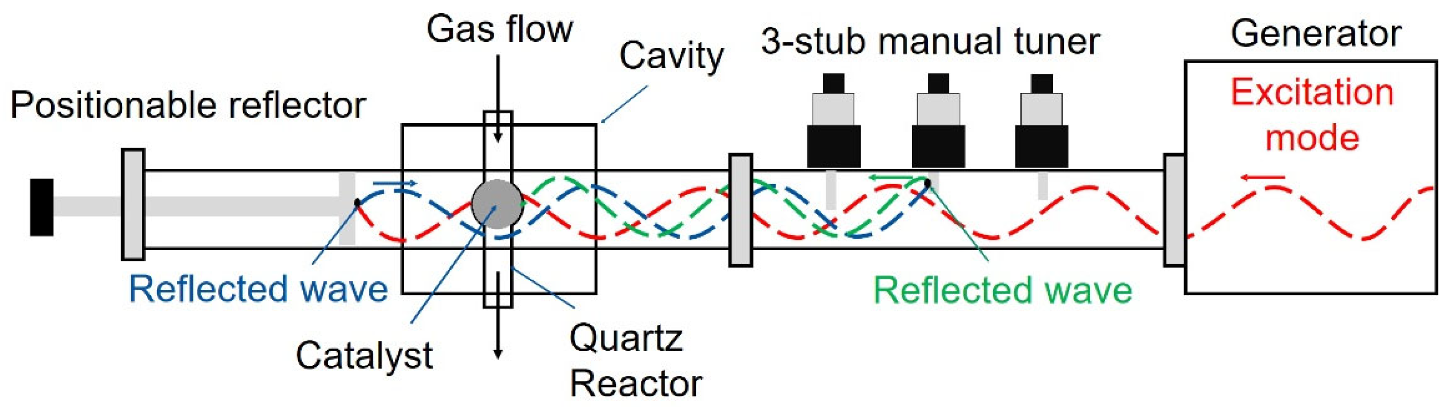
3.1. The Monomode MW-Assisted Catalysis Setup

The MW setup was supplied by Sairem, Décines-Charpieu, France, and represents a monomode MW-heterogeneous catalysis system with a fixed bed reactor. The term monomode in this context can be understood as a standing wave with a discrete frequency (2450 MHz; λ = 12.24 cm) that is directed at a target inside a cavity (see Figure 9) and subjected to multiple reflections.
The powdered catalyst is placed inside a quartz reactor with a spherical extension directly in the center of the cavity. The reactor is connected to a gas supply and the composition of the exhaust gas downstream is analyzed by means of a FTIR gas analyzer GA 2030, MKS-Technologies Deutschland GmbH, München, Germany.
The reactor is positioned directly at the center of the cavity for optimum MW exposure. Temperature recording of the catalyst bed and control is facilitated by a non-contact IR-pyrometer Infrared-Sensor CT 3M, Optris GmbH, Berlin, Germany, having a measuring range from 50 °C to 400 °C in a frequency window around 2.3 µm where quartz is IR-transparent. The IR-pyrometer is coupled to the cavity, positioned and adjusted as to realize maximum overlap of the pyrometers field of view (FOV, 5mm diameter) and the catalyst bed, and connected to a Eurotherm 2408 temperature controller, Schneider Electric Systems Germany GmbH, Limburg an der Lahn, Germany, which can be programmed by the systems control software to yield complex heating programs. An additional temperature recording is facilitated by means of a fiberoptic contact thermal sensor (FOT) type TS-3, WeidmannTechnologies Deutschland GmbH, Dresden, Germany, which is directly positioned inside the catalyst bed. The FOT is compatible with direct MW-exposure and ensures a very reliable contact temperature measurement with quick response times.
The MW-source consists of a solid-state generator which operates in a narrow, near monochromatic frequency distribution around 2450 MHz and can supply a maximum output power of 950 W. It generates a standing wave which is directed to the cavity and the reactor by a waveguide, whose dimensions are adjusted to the specific wavelength of the MW-radiation. The standing wave is then reflected between a position-tunable MW-mirror behind the cavity and a three-stub tuner in the waveguide. This setup allows for position adjustment of the wave in respect to the reactor position inside the cavity and efficient absorption of the MW-energy by well-adjustable multiple reflections. With a wavelength of 12.24 cm, the electrical field can be considered constant over the lateral extension of the reactor with an inner diameter of 9.5 mm. The remaining MW-power which is reflected back to the generator is recorded and can give an indication about the efficiency of the absorption inside the reactor. Due to additional energy losses of the radiation at the walls of the MW-system, the entire setup is connected to a water cooler. The setup described here is similar to multiple previous studies of different groups [17,29,42], and conclusions drawn in this study are thus expected to be applicable to a wide range of MW-assisted catalysis systems.

3.2. Preparation of the Catalyst

Commercially available perovskite-type La0.8Sr0.2CoO3-powders (LSC-82) were supplied by Sigma-Aldrich/Merck KGaA, Darmstadt, Germany. To ensure a homogenous gas flow in the catalysis experiment, the finely ground porous powder is pressed in a uniaxial press (13 mm, 10 tons) to create granular agglomerates, which are sieved (200–355 µm mesh width). The granulate powder is then used for the MW-catalysis tests. The sub-200 µm fraction was experimentally evaluated as well.

3.3. Catalytic Testing

For the catalytic conversion tests, 700 mg of LSC-82 perovskite material was placed inside the quartz reactor tube using quartz wool as a mechanical support. Both the sieved sub-200 µm particle size fraction and the 200–355 µm fractions were probed. The quartz reactor was placed inside the cavity of the MW-setup and connected to a gas dosing system and the FTIR-gas-analyzer. Gas mixtures of 84% nitrogen, 10% oxygen, 6% CO/N2-mixture (9% CO in N2) with a resulting CO concentration of 5400 ppm were supplied to the catalyst bed with a controlled flowrate of 100 sccm. The MW-power was set manually in the generator and the resulting temperature was recorded after a stabilization time of at least 5 min with both the FOT and IR-pyrometer. Both concentrations of CO and CO2 were monitored continuously with the FT-IR gas-analyzer described above. Because the extent of the measurement error for the resulting CO conversion values is dependent on multiple factors and difficult to quantify, we refrain from showing error bars in Figure 5, Figure 7 and Figure 9.
Before the catalytic testing, the powdered catalyst was subjected to MW-heating under nitrogen flow of 100 sccm. The temperature was controlled to 176 °C, measured by the FOT. The temperature was held constant for one hour. The activation treatment is discussed in detail in Section 2.2.
Kinetic calculations were carried out identically to the procedure reported by Wu et al. [43,44]. In order to prepare the Arrhenius-plots for the catalytical oxidation of CO, we calculated first order rate constants for every temperature according to Equation (5):
k = Q0/m × ln(1/(1 − XCO))
with:
k: First order rate constant
Q0: Gas flowrate
m: Catalyst mass
XCO: fraction of CO converted to CO2

3.4. Thermal Gradient Measurement

In order to quantify the thermal gradient within the catalyst bed, we measured the contact temperature by FOT at different depths within the powder while the MW-system was set to a constant temperature of 70 °C measured and controlled by the IR-pyrometer and temperature controller. For this measurement, the same catalyst material LSC-82 in a particle size of 200–355 µm was used while a gas flow of 100 sccm N2 was applied. For this experiment, the emissivity factor for the IR-pyrometer was set to a value of 0.8 by calibrating to a FOT contact thermal sensor at the very edge of the powder bed.

3.5. X-ray Diffraction

Powder X-ray diffraction (XRD) was performed using a STOE STADIP MP X-ray powder diffractometer (STOE and Cie GmbH, Darmstadt, Germany). The X-ray generator was equipped with a molybdenum source operating at 40 kV and 40 mA, irradiating the sample with monochromatic MoKα (λ = 0.710806 Å). XRD patterns were recorded in transmission geometry at room temperature for 240 min over a 2θ range of 2–115°, with a step size of 0.015° employing an image plate position sensitive detector.

3.6. SEM

Scanning electron microscopy (SEM) was performed on a FE-SEM LEO/Zeiss Supra 35 VP (Carl Zeiss AG, Oberkochen, Germany) equipped with an INCA x-act detector (Oxford Instruments GmbH, Wiesbaden, Germany). The sample was mounted on an aluminum stub with adhesive carbon tape.

4. Conclusions

We reported on the operation of a monomode-MW-assisted heterogeneous catalysis test system and practical experience employing a perovskite LSC-82 catalyst for the oxidation of CO to CO2. Several observations were assessed as meaningful and are presented herein to serve as a potential guideline to ensure reproducibility and comparability of results from similar systems in the community. These factors, which can directly influence the quality of the obtained data, are listed below:
  • The presence and extent of thermal gradients within the catalyst bed was found to be significant. This has both an influence on the catalytical reaction probed and implications for thermal sensing. Under certain conditions, the gradient was determined as high as 60 °C between outside and inside. Additionally, this gradient changed as a function of MW-power applied and the physical state of the catalyst. LSC-82 exhibited stronger gradients after pre-treatment in the thermal instability region. The thermal profile of the catalyst bed should be determined before commencing catalytical studies. If possible, thermal gradients should be mitigated, or at least minimized, by considerations involving the reactor design and process conditions.
  • We found the widely used IR-pyrometers of very limited reliability for the characterization of catalytical performance in MW-assisted catalytic setups. The presence of thermal gradients, non-linear temperature-power dependencies, and the sudden change of emissivity in the probed material complicate the calibration process. The obtained results based solely on IR-pyrometry are to be questioned and should always be verified with a contact thermal sensor inside the catalyst bed.
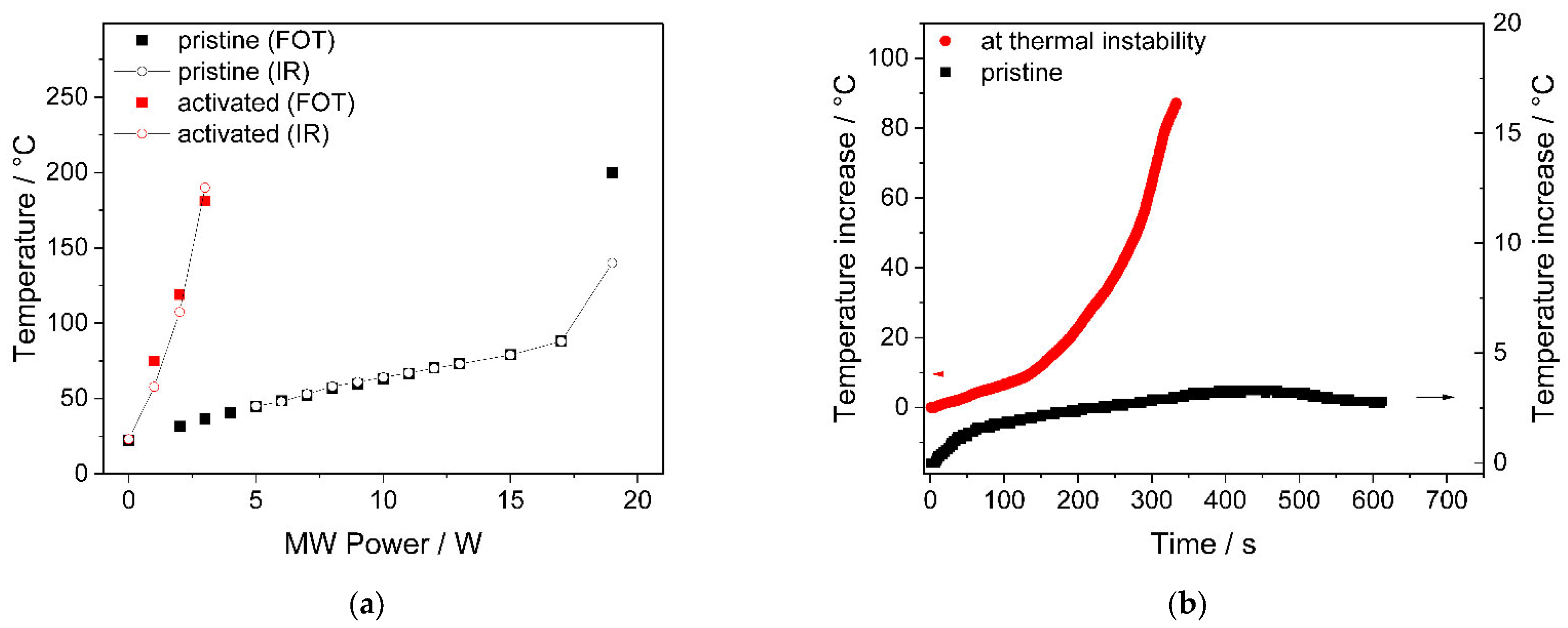
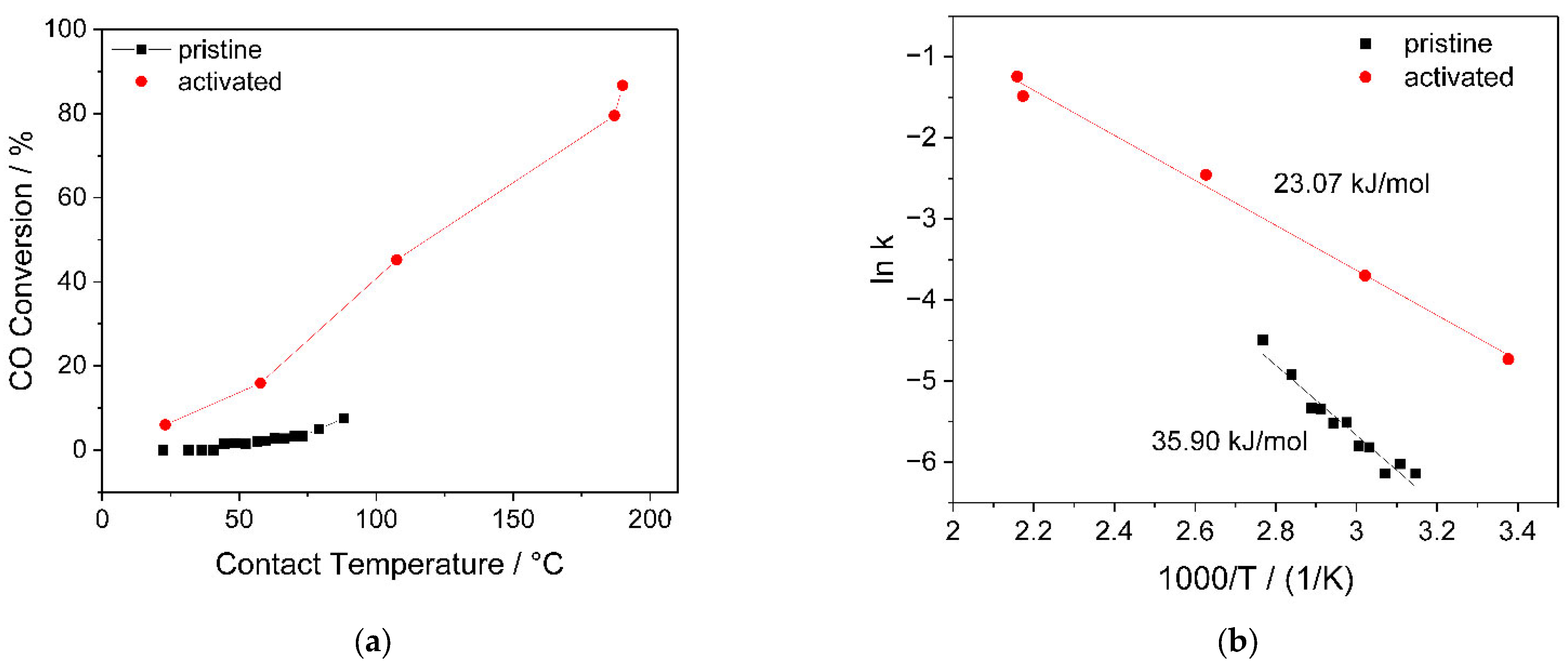
  • Many oxide materials have been reported to exhibit thermal instability under MW-heating, which leads to thermal runaway. We found the perovskite LSC-82 catalyst underwent this transition already under relatively modest conditions in the MW-system. During thermal instability, the material was found to change its MW-susceptibility (as higher temperatures were realized for fixed MW-power) and optical emissivity, which lead to the need for frequent recalibration of the IR-pyrometer. The catalyst was found to be significantly more active towards the CO oxidation after a pre-treatment in the thermal instability region. Further studies regarding this phenomenon are already in progress in our group.
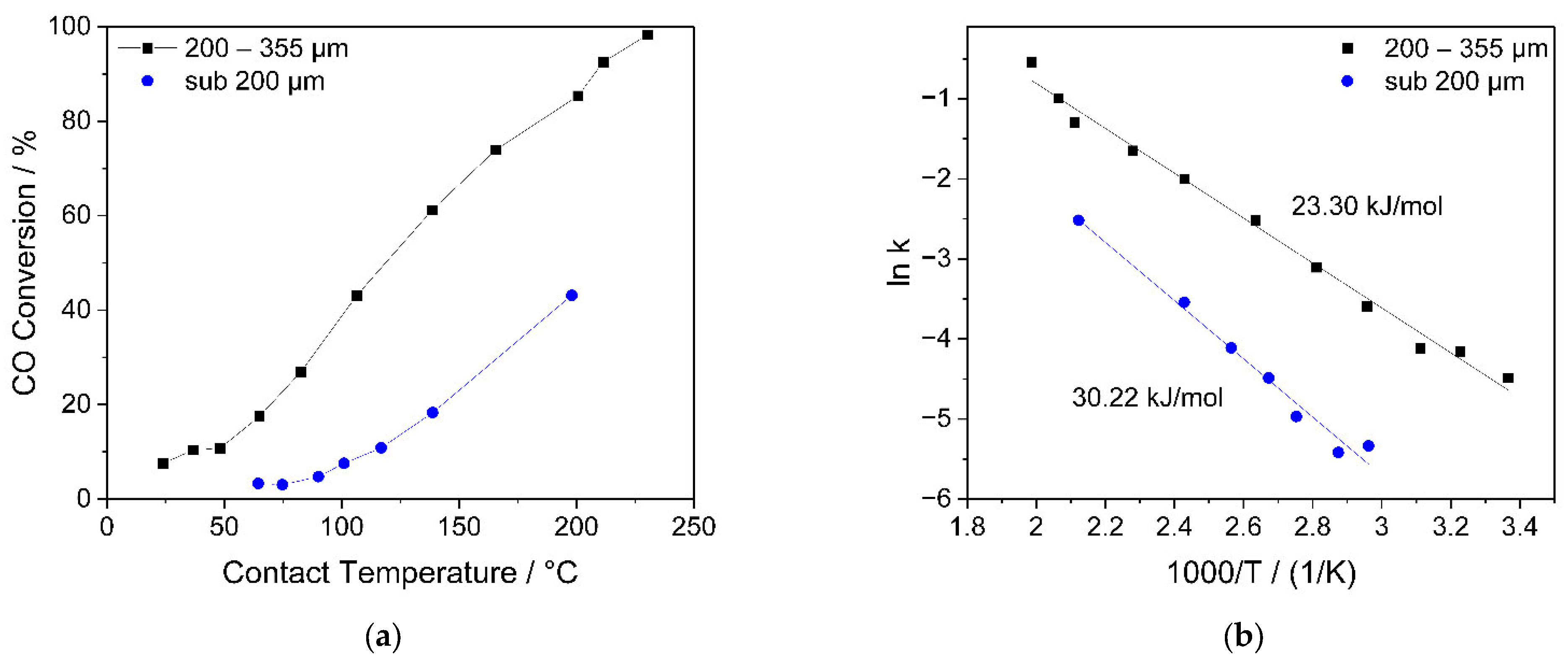
  • The particle size distribution of the powdered or granulated catalyst was found to strongly influence the obtained results for catalytic performance. It contributes to the thermal profile inside the catalyst bed under MW-irradiation and to gas transport.
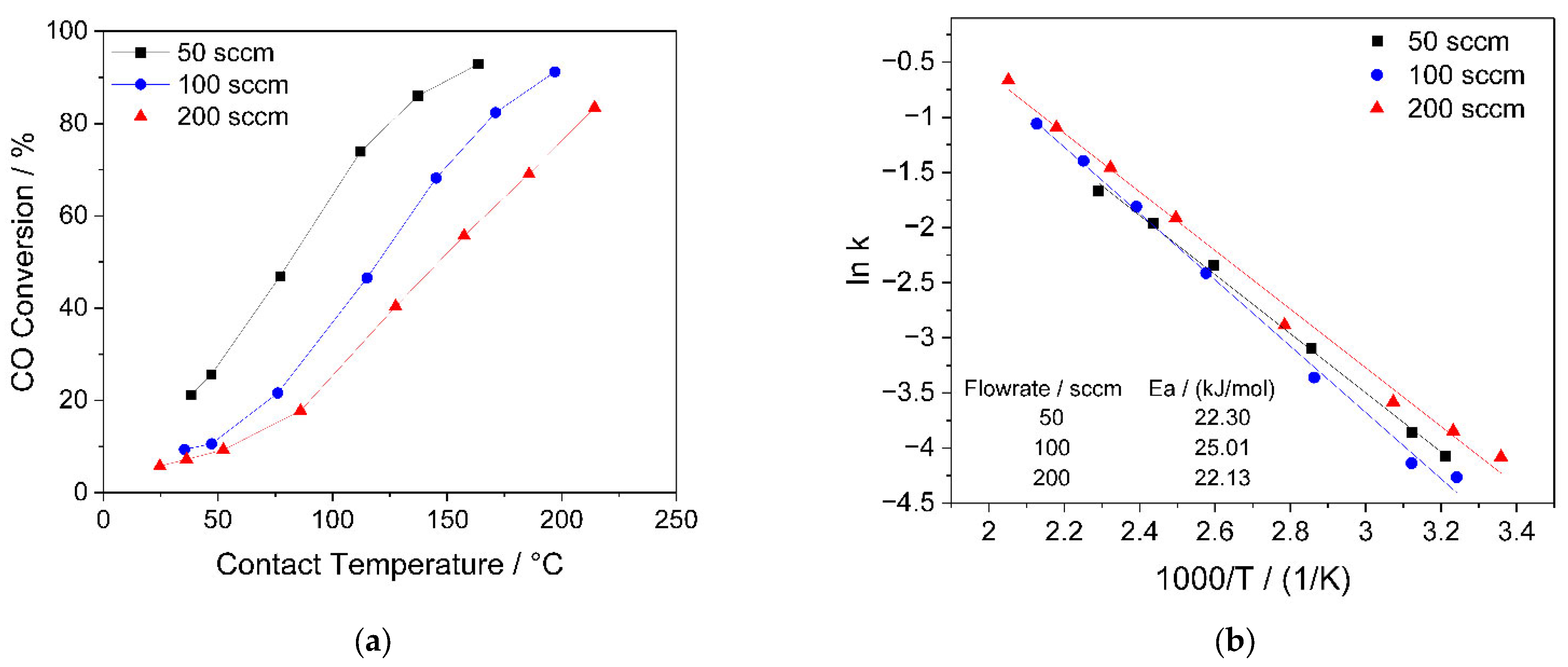
  • As for any heterogeneous catalysis experiment, we found the results to be dependent on the flowrates of the feed gas. In the case of MW-assisted synthesis this is even more relevant, as the presence of thermal gradients inside the catalyst bed and the temperature difference between catalyst and gas-phase make this situation more complex than for convectively heated systems. GHSV values should be chosen carefully and explored over a wide range.
If technical and scientific aspects as discussed above are considered, MW-assisted catalysis constitutes a very promising method to quickly and efficiently activate catalysts for a multitude of possible reactions. Catalyst materials were found to undergo material transition only in the presence of MW-activation, which can enhance reaction rates, selectivity, or even open up new pathways for advanced conversion processes. With this study, we hope to contribute to increased scientific interest in and a broader application of MW-based catalysis in fundamental as well as in application-oriented research.

Author Contributions

Conceptualization, D.R., A.A. and U.S.; Data curation, D.R., A.A. and B.W.; Formal analysis, D.R. and A.A.; Funding acquisition, U.S.; Investigation, D.R.; Methodology, D.R., A.A., B.W. and G.H.; Project administration, U.S.; Resources, U.S.; Supervision, U.S.; Visualization, D.R.; Writing—original draft, D.R.; Writing—review & editing, D.R., A.A., B.W., G.H. and U.S. All authors have read and agreed to the published version of the manuscript.

Funding

This study was funded by the Deutsche Forschungsgemeinschaft (DFG, German Research Foundation) under Germany’s Excellence Strategy–Cluster of Excellence 2186 “The Fuel Science Center”–ID: 390919832.

Data Availability Statement

Not applicable.

Acknowledgments

The authors would like to express their gratitude to Brigitte Hermanns and Tobias Storp for the recording of XRD results as well as Birgit Hahn for the SEM measurements.

Conflicts of Interest

The authors declare no conflict of interest.

References

  1. Burkardt, P.; Ottenwälder, T.; König, A.; Viell, J.; Mitsos, A.; Wouters, C.; Marquardt, W.; Pischinger, S.; Dahmen, M. Toward co-optimization of renewable fuel blend production and combustion in ultra-high efficiency SI engines. Int. J. Engine Res. 2021, 56, 1–13. [Google Scholar] [CrossRef]
  2. Leitner, W.; Klankermayer, J.; Pischinger, S.; Pitsch, H.; Kohse-Höinghaus, K. Advanced Biofuels and Beyond: Chemistry Solutions for Propulsion and Production. Angew. Chem. Int. Ed. 2017, 56, 5412–5452. [Google Scholar] [CrossRef] [PubMed]
  3. Gawande, M.B.; Shelke, S.N.; Zboril, R.; Varma, R.S. Microwave-Assisted Chemistry: Synthetic Applications for Rapid Assembly of Nanomaterials and Organics. Acc. Chem. Res. 2014, 47, 1338–1348. [Google Scholar] [CrossRef] [PubMed]
  4. Oliver Kappe, C. Microwave dielectric heating in synthetic organic chemistry. Chem. Soc. Rev. 2008, 37, 1127–1139. [Google Scholar] [CrossRef] [PubMed]
  5. Polshettiwar, V.; Varma, R.S. Aqueous microwave chemistry: A clean and green synthetic tool for rapid drug discovery. Chem. Soc. Rev. 2008, 37, 1546–1557. [Google Scholar] [CrossRef]
  6. Horikoshi, S.; Serpone, N. Role of microwaves in heterogeneous catalytic systems. Catal. Sci. Technol. 2014, 4, 1197–1210. [Google Scholar] [CrossRef]
  7. Palma, V.; Barba, D.; Cortese, M.; Martino, M.; Renda, S.; Meloni, E. Microwaves and Heterogeneous Catalysis: A Review on Selected Catalytic Processes. Catalysts 2020, 10, 246. [Google Scholar] [CrossRef] [Green Version]
  8. Stankiewicz, A.; Sarabi, F.E.; Baubaid, A.; Yan, P.; Nigar, H. Perspectives of Microwaves-Enhanced Heterogeneous Catalytic Gas-Phase Processes in Flow Systems. Chem. Rec. 2019, 19, 40–50. [Google Scholar] [CrossRef] [Green Version]
  9. Will, H.; Scholz, P.; Ondruschka, B. Heterogeneous Gas-Phase Catalysis Under Microwave Irradiation—A New Multi-Mode Microwave Applicator. Top. Catal. 2004, 29, 175–182. [Google Scholar] [CrossRef]
  10. Priecel, P.; Lopez-Sanchez, J.A. Advantages and Limitations of Microwave Reactors: From Chemical Synthesis to the Catalytic Valorization of Biobased Chemicals. ACS Sustain. Chem. Eng. 2019, 7, 3–21. [Google Scholar] [CrossRef] [Green Version]
  11. Mishra, R.R.; Sharma, A.K. Microwave–material interaction phenomena: Heating mechanisms, challenges and opportunities in material processing. Compos. Part A Appl. Sci. Manuf. 2016, 81, 78–97. [Google Scholar] [CrossRef]
  12. Peña, M.A.; Fierro, J.L.G. Chemical Structures and Performance of Perovskite Oxides. Chem. Rev. 2001, 101, 1981–2018. [Google Scholar] [CrossRef] [PubMed]
  13. Sun, J.; Wang, W.; Yue, Q. Review on Microwave-Matter Interaction Fundamentals and Efficient Microwave-Associated Heating Strategies. Materials 2016, 9, 231. [Google Scholar] [CrossRef] [PubMed] [Green Version]
  14. Jacob, J.; Chia, L.H.L.; Boey, F.Y.C. Thermal and non-thermal interaction of microwave radiation with materials. J. Mater. Sci. 1995, 30, 5321–5327. [Google Scholar] [CrossRef]
  15. Xu, W.; Zhou, J.; Su, Z.; Ou, Y.; You, Z. Microwave catalytic effect: A new exact reason for microwave-driven heterogeneous gas-phase catalytic reactions. Catal. Sci. Technol. 2016, 6, 698–702. [Google Scholar] [CrossRef]
  16. Nishioka, M.; Miyakawa, M.; Daino, Y.; Kataoka, H.; Koda, H.; Sato, K.; Suzuki, T.M. Single-Mode Microwave Reactor Used for Continuous Flow Reactions under Elevated Pressure. Ind. Eng. Chem. Res. 2013, 52, 4683–4687. [Google Scholar] [CrossRef]
  17. Einaga, H.; Nasu, Y.; Oda, M.; Saito, H. Catalytic performances of perovskite oxides for CO oxidation under microwave irradiation. Chem. Eng. J. 2016, 283, 97–104. [Google Scholar] [CrossRef]
  18. Wu, X.; Fischer, M.; Nolte, A.; Lenßen, P.; Wang, B.; Ohlerth, T.; Wöll, D.; Heufer, K.A.; Pischinger, S.; Simon, U. Perovskite Catalyst for In-Cylinder Coating to Reduce Raw Pollutant Emissions of Internal Combustion Engines. ACS Omega 2022, 7, 5340–5349. [Google Scholar] [CrossRef]
  19. Beckers, J.; van der Zande, L.M.; Rothenberg, G. Clean Diesel Power via Microwave Susceptible Oxidation Catalysts. Chem. Phys. Chem. 2006, 7, 747–755. [Google Scholar] [CrossRef]
  20. Keav, S.; Matam, S.K.; Ferri, D.; Weidenkaff, A. Structured Perovskite-Based Catalysts and Their Application as Three-Way Catalytic Converters—A Review. Catalysts 2014, 4, 226–255. [Google Scholar] [CrossRef] [Green Version]
  21. Will, H.; Scholz, P.; Ondruschka, B. Microwave-Assisted Heterogeneous Gas-Phase Catalysis. Chem. Eng. Technol. 2004, 27, 113–122. [Google Scholar] [CrossRef]
  22. Royer, S.; Duprez, D.; Can, F.; Courtois, X.; Batiot-Dupeyrat, C.; Laassiri, S.; Alamdari, H. Perovskites as Substitutes of Noble Metals for Heterogeneous Catalysis: Dream or Reality. Chem. Rev. 2014, 114, 10292–10368. [Google Scholar] [CrossRef] [PubMed]
  23. Gangurde, L.S.; Sturm, G.S.J.; Devadiga, T.J.; Stankiewicz, A.I.; Stefanidis, G.D. Complexity and Challenges in Noncontact High Temperature Measurements in Microwave-Assisted Catalytic Reactors. Ind. Eng. Chem. Res. 2017, 56, 13379–13391. [Google Scholar] [CrossRef]
  24. Durka, T.; Stefanidis, G.D.; Gerven, T.V.; Stankiewicz, A. On the accuracy and reproducibility of fiber optic (FO) and infrared (IR) temperature measurements of solid materials in microwave applications. Meas. Sci. Technol. 2010, 21, 045108. [Google Scholar] [CrossRef]
  25. Kappe, C.O. How to measure reaction temperature in microwave-heated transformations. Chem. Soc. Rev. 2013, 42, 4977–4990. [Google Scholar] [CrossRef] [PubMed]
  26. Liu, Q.; You, Z.; Zeng, S.; Guo, H.W. Infrared properties of Mg-doped LaFeO3 prepared by sol–gel method. J. Sol-Gel Sci. Technol. 2016, 80, 860–866. [Google Scholar] [CrossRef]
  27. Liu, J.W.; Wang, J.J.; Gao, H.T. Infrared Emissivities and Microwave Absorption Properties of Perovskite La1-xCaxMnO3 (0 ≤ x ≤ 0.5). Mater. Sci. Forum 2018, 914, 96–101. [Google Scholar] [CrossRef]
  28. Herman, I.P. Chapter 13—Pyrometry. In Optical Diagnostics for Thin Film Processing; Herman, I.P., Ed.; Academic Press: San Diego, CA, USA, 1996; pp. 591–617. [Google Scholar] [CrossRef]
  29. Serra, J.M.; Borrás-Morell, J.F.; García-Baños, B.; Balaguer, M.; Plaza-González, P.; Santos-Blasco, J.; Catalán-Martínez, D.; Navarrete, L.; Catalá-Civera, J.M. Hydrogen production via microwave-induced water splitting at low temperature. Nat. Energy 2020, 5, 910–919. [Google Scholar] [CrossRef]
  30. Tatsuo, O.; Akiko, W. Simple suppressing method of thermal runaway in microwave heating of zeolite and its application. Phys. Chem. Comm. 2001, 4, 18–20. [Google Scholar] [CrossRef]
  31. Vriezinga, C.A.; Sánchez-Pedreño, S.; Grasman, J. Thermal runaway in microwave heating: A mathematical analysis. Appl. Math. Model. 2002, 26, 1029–1038. [Google Scholar] [CrossRef]
  32. Kriegsmann, G.A. Thermal runaway in microwave heated ceramics: A one-dimensional model. J. Appl. Phys. 1992, 71, 1960–1966. [Google Scholar] [CrossRef]
  33. Rybakov, K.I.; Egorov, S.V.; Eremeev, A.G.; Kholoptsev, V.V.; Plotnikov, I.V.; Sorokin, A.A. Ultra-rapid microwave sintering employing thermal instability and resonant absorption. J. Mater. Res. 2019, 34, 2620–2634. [Google Scholar] [CrossRef]
  34. Das, A.; Paranjpe, S.K.; Joy, P.A.; Date, S.K. Neutron depolarization and diffraction studies in cluster glass La0.5Sr0.5CoO3. J. Alloy. Compd. 2001, 326, 101–104. [Google Scholar] [CrossRef]
  35. Kharkhan, D.N.; Pilloud, D.; Bruyère, S.; Migot, S.; Barrat, S.; Capon, F. Influence of as-deposited non-uniform stoichiometry on thermochromic properties of LaCoO3 selective layers. J. Appl. Phys. 2020, 127, 015304. [Google Scholar] [CrossRef]
  36. Horikoshi, S.; Schiffmann, R.F.; Fukushima, J.; Serpone, N. Microwave Materials Processing in Solid Media. In Microwave Chemical and Materials Processing: A Tutorial; Horikoshi, S., Schiffmann, R.F., Fukushima, J., Serpone, N., Eds.; Springer: Singapore, 2018; pp. 213–241. [Google Scholar]
  37. Krech, T.; Möser, C.; Emmerich, R.; Scholz, P.; Ondruschka, B.; Cihlar, J. Catalytic and Heating Behavior of Nanoscaled Perovskites under Microwave Radiation. Chem. Eng. Technol. 2008, 31, 1000–1006. [Google Scholar] [CrossRef]
  38. Muley, P.D.; Wang, Y.; Hu, J.; Shekhawat, D. Microwave-assisted heterogeneous catalysis. In Catalysis; The Royal Society of Chemistry: London, UK, 2021; Volume 33, pp. 1–37. [Google Scholar] [CrossRef]
  39. Zhang, M.; Wang, M.; Xu, B.; Ma, D. How to Measure the Reaction Performance of Heterogeneous Catalytic Reactions Reliably. Joule 2019, 3, 2876–2883. [Google Scholar] [CrossRef]
  40. Ascaso, S.; Elena Gálvez, M.; Da Costa, P.; Moliner, R.; Lázaro Elorri, M.J. Influence of gas hourly space velocity on the activity of monolithic catalysts for the simultaneous removal of soot and NOx. Comptes Rendus Chim. 2015, 18, 1007–1012. [Google Scholar] [CrossRef]
  41. Wang, H.; Liu, J.; Zhao, Z.; Wei, Y.; Xu, C. Comparative study of nanometric Co-, Mn- and Fe-based perovskite-type complex oxide catalysts for the simultaneous elimination of soot and NOx from diesel engine exhaust. Catal. Today 2012, 184, 288–300. [Google Scholar] [CrossRef]
  42. Zhang-Steenwinkel, Y.; Castricum, H.L.; Beckers, J.; Eiser, E.; Bliek, A. Dielectric heating effects on the activity and SO2 resistance of La0.8Ce0.2MnO3 perovskite for methane oxidation. J. Catal. 2004, 221, 523–531. [Google Scholar] [CrossRef] [Green Version]
  43. Wu, Y.; Cordier, C.; Berrier, E.; Nuns, N.; Dujardin, C.; Granger, P. Surface reconstructions of LaCo1−xFexO3 at high temperature during N2O decomposition in realistic exhaust gas composition: Impact on the catalytic properties. Appl. Catal. B Environ. 2013, 140, 151–163. [Google Scholar] [CrossRef]
  44. Wu, Y.; Ni, X.; Beaurain, A.; Dujardin, C.; Granger, P. Stoichiometric and non-stoichiometric perovskite-based catalysts: Consequences on surface properties and on catalytic performances in the decomposition of N2O from nitric acid plants. Appl. Catal. B Environ. 2012, 125, 149–157. [Google Scholar] [CrossRef]
Figure 1. Schematic representation of different types of thermal gradients resulting from MW-heating (a) and conductive heating (b).
Catalysts 12 00802 g001
Figure 2. (a) Schematic representation of the spherical quartz reactor with catalyst filling and a MW-induced thermal gradient indicated by color. (b) Real thermal gradient determined by FOT contact measurement in an LSC-82 powder bed exposed and controlled to MW radiation with a fixed set temperature of 70 °C by an IR-pyrometer.
Catalysts 12 00802 g002
Figure 3. (a) Measured temperatures of an LSC-82 catalyst powder for both the FOT contact thermal sensor and IR-pyrometer as a function of applied MW-power after calibration at 110 °C (left axis), difference between the two thermal sensing methods for the same measurement data (right axis). (b) Temperature dependent CO conversion over an LSC-82 catalyst, as determined by both contact temperature measurement and IR-pyrometry. The IR-pyrometer had been calibrated to the FOT temperature at 110 °C.
Catalysts 12 00802 g003
Figure 4. (a) Heating behavior of an LSC-82 catalyst under MW-radiation before and after a sustained activation treatment under thermal instability conditions. (b) Normalized FOT-temperature response vs. time to an incremental 1 W power increase before (black arrow, right y-axis) and at the thermal instability region (red arrow, left y-axis). The measurement at thermal instability region had to be stopped to avoid damage to the sensor.
Catalysts 12 00802 g004
Figure 5. (a) CO oxidation over an LSC-82 catalyst under MW-heating before (pristine) and after (activated) a sustained activation treatment under thermal instability conditions. (b) The same data represented as Arrhenius plot.
Catalysts 12 00802 g005
Figure 6. (a) XRD patterns of the powdered catalyst before (as pressed) and after catalysis. All reflections can be assigned to a rhombohedral perovskite (space group R -3 c), reference positions adapted from Crystallography Open Database (COD) entry 1525854 [34]. (b) SEM images in SE mode of the same powders in 5 k× and 50 k× magnification.
Catalysts 12 00802 g006
Figure 7. (a) Temperature-dependent catalytic CO conversion over an LSC-82 catalyst as a function of different particle size distributions of the catalyst material. (b) Arrhenius representation of the same data.
Catalysts 12 00802 g007
Figure 8. (a) Temperature-dependent catalytic CO conversion over an LSC-82 catalyst as a function of different total flowrate and (b) Arrhenius-plot of the data.
Catalysts 12 00802 g008
Figure 9. Schematic representation of the monomode MW-catalysis setup. A standing wave (red) originates in the solid-state generator which is subjected to multiple reflections first at the manually positionable reflector (blue) and again at the 3-stub manual tuner (green). By this manual optimization process the MW-power directed towards the sample is maximized, while the power reflected back to the generator is minimized.
Catalysts 12 00802 g009
Publisher’s Note: MDPI stays neutral with regard to jurisdictional claims in published maps and institutional affiliations.

