
Graphyne Nanotubes as Promising Sodium-Ion Battery Anodes

 and
and 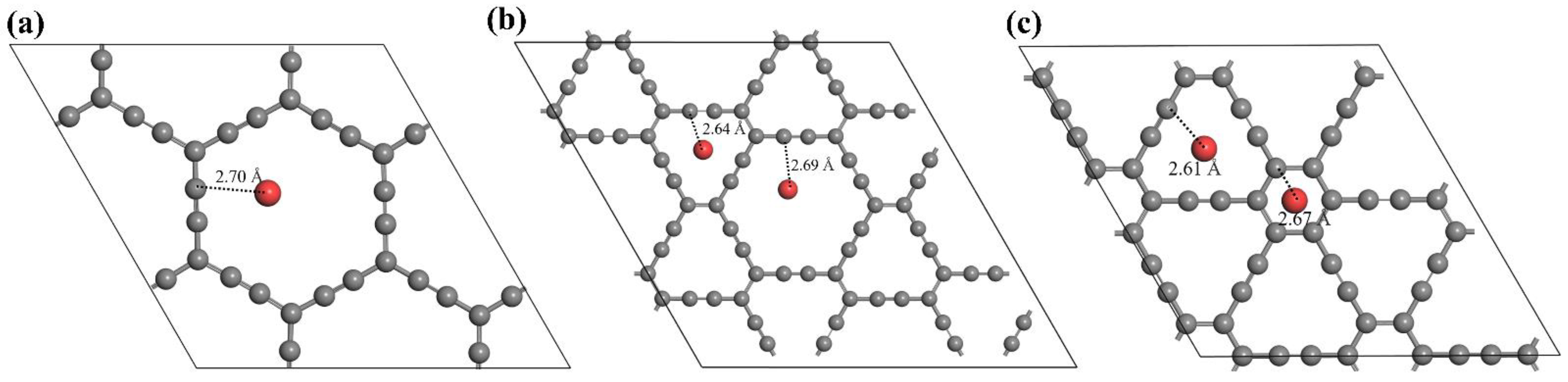
Abstract
:1. Introduction
2. Computational Method
3. Results and Discussion
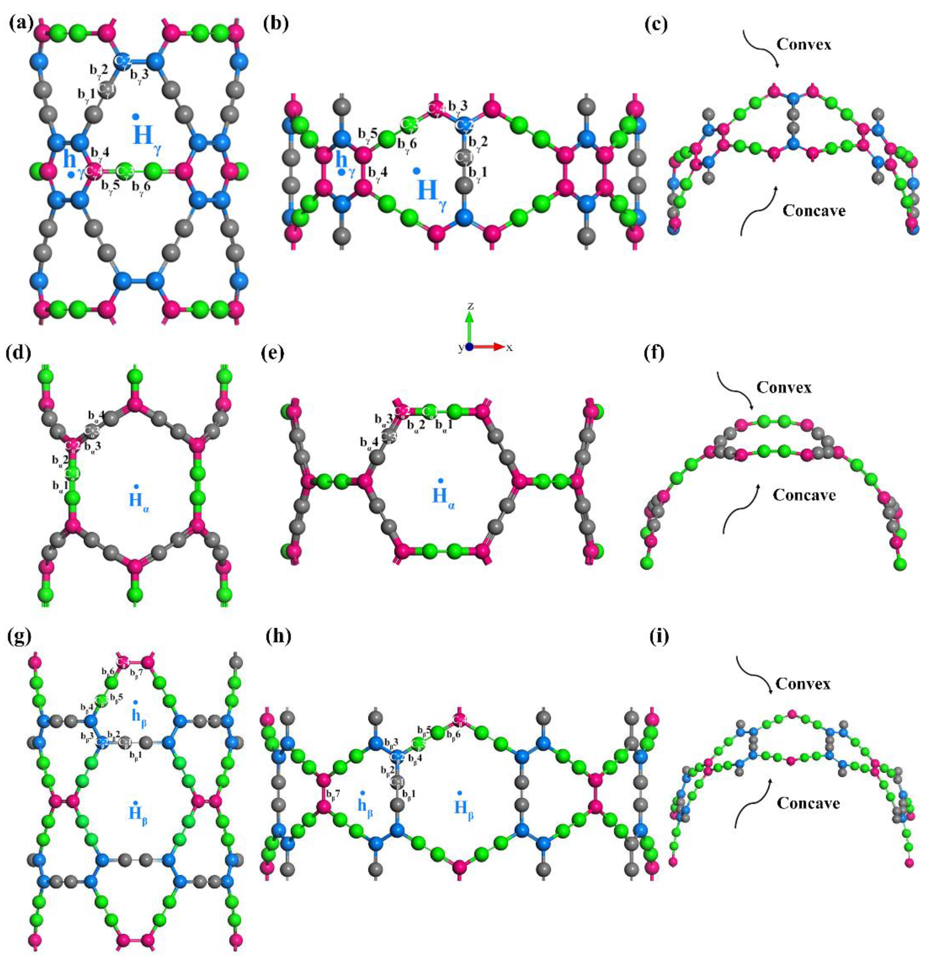
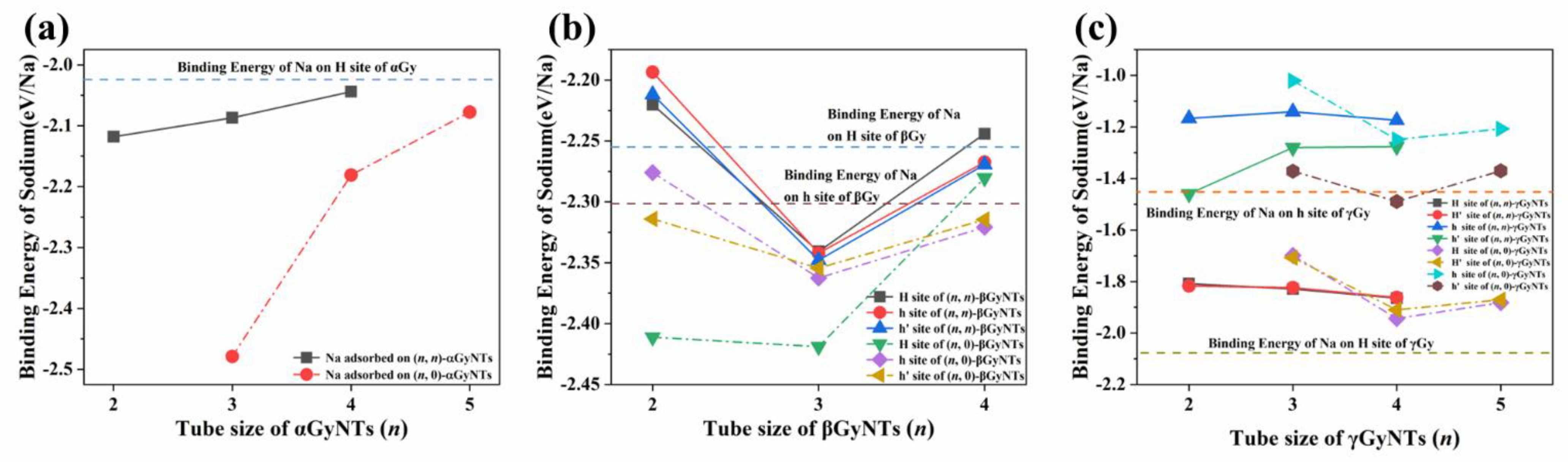
3.1. Single Na Adsorption on GyNTs
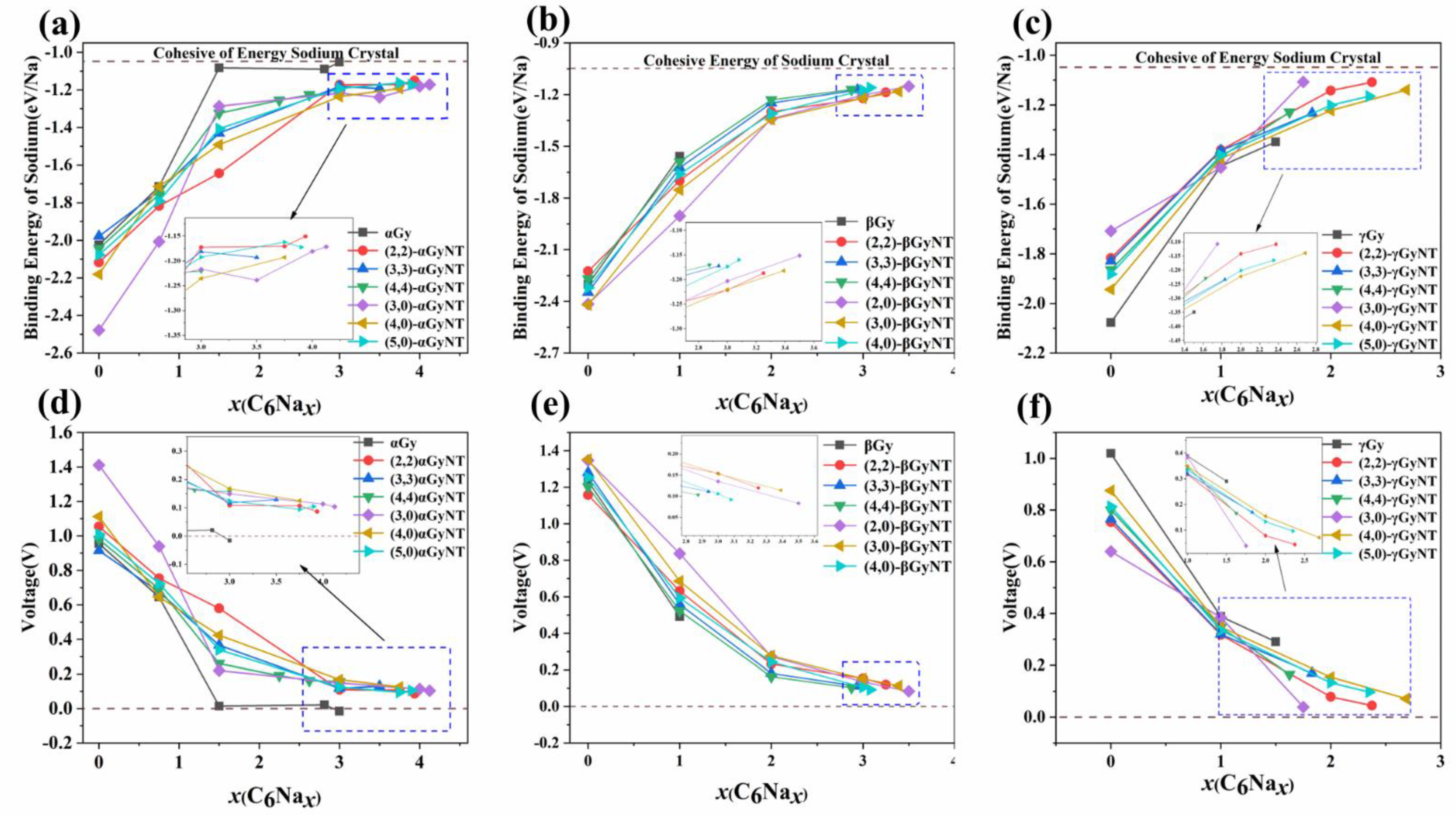
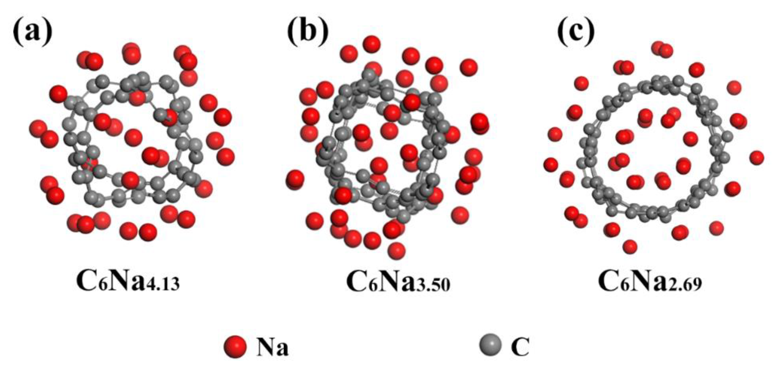
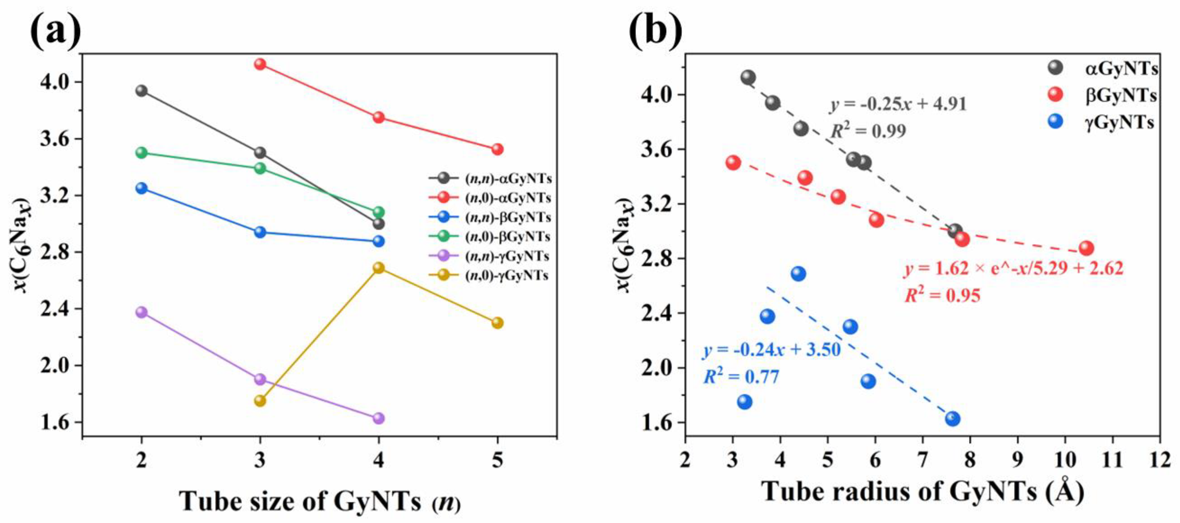
3.2. Sodium Storage Capacity of GyNTs
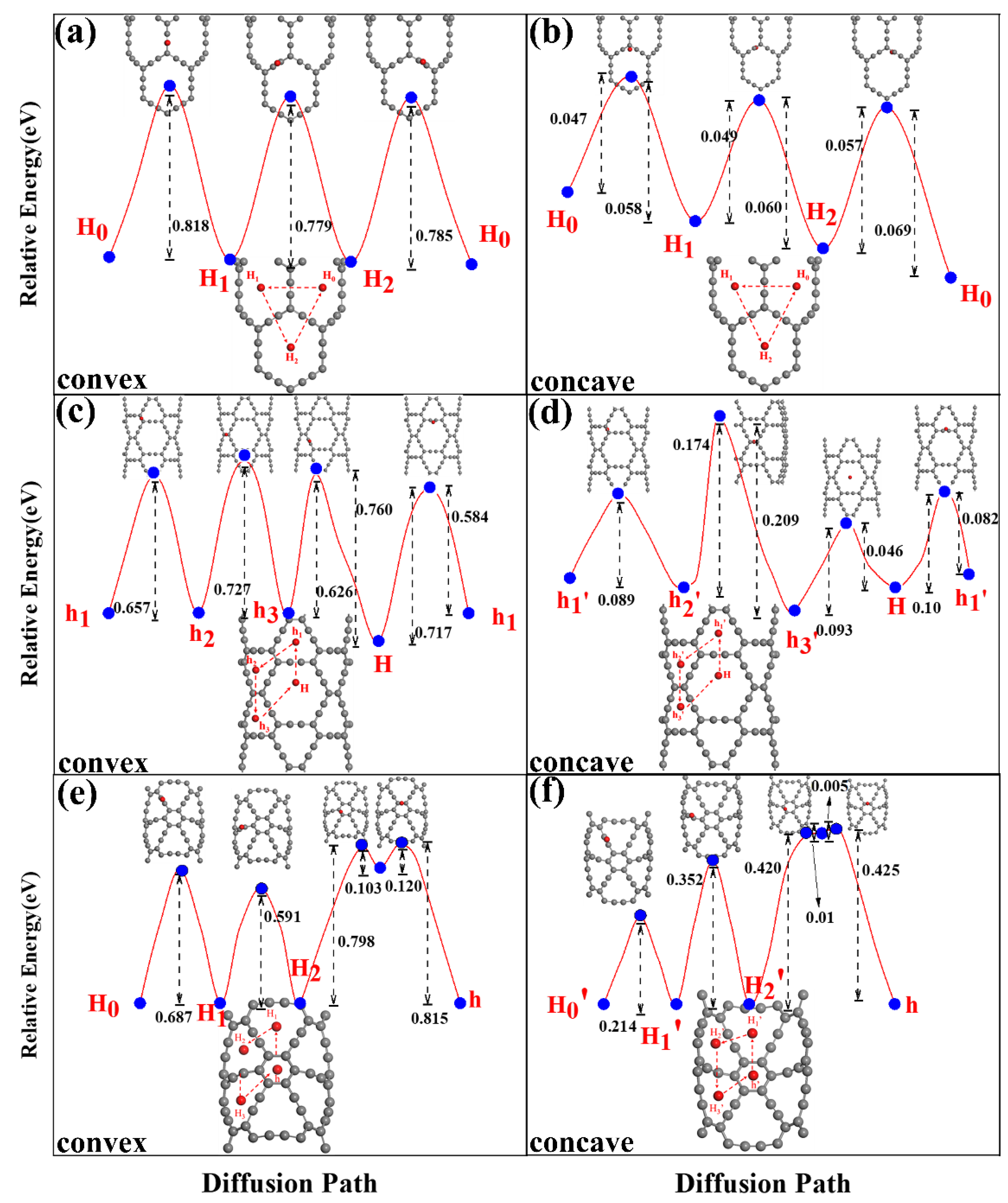
3.3. Sodium Diffusion and Migration on GyNTs
4. Conclusions
Supplementary Materials
Author Contributions
Funding
Institutional Review Board Statement
Informed Consent Statement
Data Availability Statement
Conflicts of Interest
References
- Tarascon, J.M. Is lithium the new gold? Nat. Chem. 2010, 2, 510. [Google Scholar] [CrossRef]
- Dunn, B.; Kamath, H.; Tarascon, J.M. Electrical energy storage for the grid: A battery of choices. Science 2011, 334, 928–935. [Google Scholar] [CrossRef] [PubMed] [Green Version]
- Whittingham, M.S. Electrical energy storage and intercalation chemistry. Science 1976, 192, 1126–1127. [Google Scholar] [CrossRef] [PubMed]
- Tarascon, J.M.; Armand, M. Issues and challenges facing rechargeable lithium batteries. Nature 2001, 414, 359–367. [Google Scholar] [CrossRef] [PubMed]
- Kong, H.; Lv, C.; Wu, Y.; Yan, C.; Chen, G. Integration of cobalt selenide nanocrystals with interlayer expanded 3D Se/N Co-doped carbon networks for superior sodium-ion storage. J. Energy Chem. 2021, 55, 169–175. [Google Scholar] [CrossRef]
- Pan, H.L.; Hu, Y.S.; Chen, L.Q. Room-temperature stationary sodium-ion batteries for large-scale electric energy storage. Energy Environ. Sci. 2013, 6, 2338–2360. [Google Scholar] [CrossRef]
- Palomares, V.; Serras, P.; Villaluenga, I.; Hueso, K.B.; Carretero-González, J.; Rojo, T. Na-ion batteries, recent advances and present challenges to become low cost energy storage systems. Energy Environ. Sci. 2012, 5, 5884–5901. [Google Scholar] [CrossRef]
- Zhu, C.; Mu, X.; van Aken, P.A.; Yu, Y.; Maier, J. Single-Layered Ultrasmall Nanoplates of MoS2 Embedded in Carbon Nanofibers with Excellent Electrochemical Performance for Lithium and Sodium Storage. Angew. Chem. Int. Ed. 2014, 53, 2152–2156. [Google Scholar] [CrossRef] [PubMed]
- Hwang, J.Y.; Myung, S.T.; Sun, Y.K. Sodium-ion batteries: Present and future. Chem. Soc. Rev. 2017, 46, 3529–3614. [Google Scholar] [CrossRef] [Green Version]
- Lee, B.; Paek, E.; Mitlin, D.; Lee, S.W. Sodium Metal Anodes: Emerging Solutions to Dendrite Growth. Chem. Rev. 2019, 119, 5416–5460. [Google Scholar] [CrossRef]
- Zheng, X.Y.; Bommier, C.; Luo, W.; Jiang, L.H.; Hao, Y.N.; Huang, Y.H. Sodium metal anodes for room-temperature sodium-ion batteries: Applications, challenges and solutions. Energy Storage Mater. 2019, 16, 6–23. [Google Scholar] [CrossRef]
- Dou, X.W.; Hasa, I.; Saurel, D.; Vaalma, C.; Wu, L.M.; Buchholz, D.; Bresser, D.; Komaba, S.; Passerini, S. Hard carbons for sodium-ion batteries: Structure, analysis, sustainability and electrochemistry. Mater. Today 2019, 23, 87–104. [Google Scholar] [CrossRef]
- Jiang, H.; Gu, J.X.; Zheng, X.S.; Liu, M.; Qiu, X.Q.; Wang, L.B.; Li, W.Z.; Chen, Z.F.; Ji, X.B.; Li, J. Defect-rich and ultrathin N doped carbon nanosheets as advanced trifunctional metal-free electrocatalysts for the ORR, OER and HER. Energy Environ. Sci. 2019, 12, 322–333. [Google Scholar] [CrossRef]
- Xia, J.; Liu, L.; Jamil, S.; Xie, J.J.; Yan, H.X.; Yuan, Y.T.; Zhang, Y.; Nie, S.; Pan, J.; Wang, X.Y.; et al. Free-standing SnS/C nanofiber anodes for ultralong cycle-life lithium-ion batteries and sodium-ion batteries. Energy Storage Mater. 2019, 17, 1–11. [Google Scholar] [CrossRef]
- Fang, G.Z.; Wang, Q.C.; Zhou, J.; Lei, Y.P.; Chen, Z.X.; Wang, Z.Q.; Pan, A.Q.; Liang, S.Q. Metal organic framework-templated synthesis of bimetallic selenides with rich phase boundaries for Sodium-Ion storage and oxygen evolution reaction. ACS Nano 2019, 13, 5635–5645. [Google Scholar] [CrossRef] [PubMed]
- Liu, Y.; Fang, Y.J.; Zhao, Z.W.; Yuan, C.Z.; Lou, X.W. A ternary Fe1-xS@porous carbon nanowires/reduced graphene oxide hybrid film electrode with superior volumetric and gravimetric capacities for flexible sodium ion batteries. Adv. Energy Mater. 2019, 9, 1803052. [Google Scholar] [CrossRef]
- Wang, L.; Wei, Z.X.; Mao, M.L.; Wang, H.X.; Li, Y.T.; Ma, J.M. Metal oxide/graphene composite anode materials for sodium-ion batteries. Energy Storage Mater. 2019, 16, 434–454. [Google Scholar] [CrossRef]
- Luo, W.; Hu, L. Na Metal Anode: “Holy Grail” for Room-Temperature Na-Ion Batteries? ACS Cent. Sci. 2015, 1, 420–422. [Google Scholar] [CrossRef]
- Hartmann, P.; Bender, C.L.; Vračar, M.; Dürr, A.K.; Garsuch, A.; Janek, J.; Adelhelm, P. A rechargeable room-temperature sodium superoxide (NaO2) battery. Nat. Mater. 2013, 12, 228–232. [Google Scholar] [CrossRef]
- Yabuuchi, N.; Kubota, K.; Dahbi, M.; Komaba, S. Research Development on Sodium-Ion Batteries. Chem. Rev. 2014, 114, 11636–11682. [Google Scholar] [CrossRef]
- Kang, H.Y.; Liu, Y.C.; Cao, K.Z.; Zhao, Y.; Jiao, L.F.; Wang, Y.J.; Yuan, H.T. Update on anode materials for Na-ion batteries. J. Mater. Chem. A 2015, 3, 17899–17913. [Google Scholar] [CrossRef]
- Saurel, D.; Orayech, B.; Xiao, B.; Carriazo, D.; Li, X.; Rojo, T. From Charge Storage Mechanism to Performance: A Roadmap toward High Specific Energy Sodium-Ion Batteries through Carbon Anode Optimization. Adv. Energy Mater. 2018, 8, 1703268. [Google Scholar] [CrossRef]
- Kang, B.; Moon, J.H.; Lee, J.Y. Size dependent electronic band structures of beta- and gamma-graphyne nanotubes. RSC Adv. 2015, 5, 80118–80121. [Google Scholar] [CrossRef]
- Lu, L.L.; Ge, J.; Yang, J.N.; Chen, S.M.; Yao, H.B.; Zhou, F.; Yu, S.H. Free-Standing Copper Nanowire Network Current Collector for Improving Lithium Anode Performance. Nano Lett. 2016, 16, 4431–4437. [Google Scholar] [CrossRef] [PubMed]
- Zhang, R.; Cheng, X.B.; Zhao, C.Z.; Peng, H.J.; Shi, J.L.; Huang, J.Q.; Wang, J.; Wei, F.; Zhang, Q. Conductive Nanostructured Scaffolds Render Low Local Current Density to Inhibit Lithium Dendrite Growth. Adv. Mater. 2016, 28, 2155–2162. [Google Scholar] [CrossRef]
- Wen, Y.; He, K.; Zhu, Y.J.; Han, F.D.; Xu, Y.H.; Matsuda, I.; Ishii, Y.; Cumings, J.; Wang, C.S. Expanded graphite as superior anode for sodium-ion batteries. Nat. Commun. 2014, 5, 4033. [Google Scholar] [CrossRef] [Green Version]
- Jian, Z.L.; Xing, Z.Y.; Bommier, C.; Li, Z.F.; Ji, X.L. Hard Carbon Microspheres: Potassium-Ion Anode Versus Sodium-Ion Anode. Adv. Energy Mater. 2016, 6, 1501874. [Google Scholar] [CrossRef]
- Tang, K.; Fu, L.J.; White, R.J.; Yu, L.H.; Titirici, M.M.; Antonietti, M.; Maier, J. Hollow Carbon Nanospheres with Superior Rate Capability for Sodium-Based Batteries. Adv. Energy Mater. 2012, 2, 873–877. [Google Scholar] [CrossRef]
- Ma, C.; Xu, T.; Wang, Y. Advanced carbon nanostructures for future high performance sodium metal anodes. Energy Storage Mater. 2020, 25, 811–826. [Google Scholar] [CrossRef]
- Xu, J.T.; Wang, M.; Wickramaratne, N.P.; Jaroniec, M.; Dou, S.X.; Dai, L.M. High-Performance Sodium Ion Batteries Based on a 3D Anode from Nitrogen-Doped Graphene Foams. Adv. Mater. 2015, 27, 2042–2048. [Google Scholar] [CrossRef]
- Zhang, S.; He, J.; Zheng, J.; Huang, C.; Lv, Q.; Wang, K.; Wang, N.; Lan, Z. Porous graphdiyne applied for sodium ion storage. J. Mater. Chem. A 2016, 5, 2045–2051. [Google Scholar] [CrossRef]
- Baughman, R.H.; Eckhardt, H.; Kertesz, M. Structure-property predictions for new planar forms of carbon: Layered phases containing sp2 and sp atoms. J. Chem. Phys. 1987, 87, 6687–6699. [Google Scholar] [CrossRef]
- Li, G.; Li, Y.; Liu, H.; Guo, Y.; Li, Y.; Zhu, D. Architecture of graphdiyne nanoscale films. Chem. Commun. 2010, 46, 3256–3258. [Google Scholar] [CrossRef]
- Kang, B.; Lee, J.Y. Graphynes as Promising Cathode Material of Fuel Cell: Improvement of Oxygen Reduction Efficiency. J. Phys. Chem. C 2014, 118, 12035–12040. [Google Scholar] [CrossRef]
- Kang, B.; Liu, H.; Lee, J.Y. Oxygen adsorption on single layer graphyne: A DFT study. Phys. Chem. Chem. Phys. 2014, 16, 974–980. [Google Scholar] [CrossRef] [PubMed]
- Hwang, H.J.; Koo, J.; Park, M.; Park, N.; Kwon, Y.; Lee, H. Multilayer Graphynes for Lithium Ion Battery Anode. J. Phys. Chem. C 2013, 117, 6919–6923. [Google Scholar] [CrossRef]
- Yang, Z.; Zhang, C.F.; Hou, Z.F.; Wang, X.; He, J.J.; Li, X.D.; Song, Y.W.; Wang, N.; Wang, K.; Wang, H.L.; et al. Porous hydrogen substituted graphyne for high capacity and ultra-stable sodium ion storage. J. Mater. Chem. A 2019, 7, 11186–11194. [Google Scholar] [CrossRef]
- Wang, K.; Wang, N.; He, J.J.; Yang, Z.; Shen, X.Y.; Huang, C.S. Preparation of 3D Architecture Graphdiyne Nanosheets for High-Performance Sodium-Ion Batteries and Capacitors. ACS Appl. Mater. Inter. 2017, 9, 40604–40613. [Google Scholar] [CrossRef] [PubMed]
- Yang, C.F.; Qiao, C.; Chen, Y.; Zhao, X.Q.; Wu, L.L.; Li, Y.; Jia, Y.; Wang, S.Y.; Cui, X.L. Nitrogen Doped gamma-Graphyne: A Novel Anode for High-Capacity Rechargeable Alkali-Ion Batteries. Small 2020, 16, 1907365. [Google Scholar] [CrossRef] [PubMed]
- Xu, Z.; Lv, X.; Li, J.; Chen, J.; Liu, Q. A promising anode material for sodium-ion battery with high capacity and high diffusion ability: Graphyne and graphdiyne. RSC Adv. 2016, 6, 25594–25600. [Google Scholar] [CrossRef]
- Ma, J.; Yuan, Y.; Wu, S.; Lee, J.Y.; Kang, B. γ-Graphyne nanotubes as promising lithium-ion battery anodes. Appl. Surf. Sci. 2020, 531, 147343. [Google Scholar] [CrossRef]
- Zhou, W.; Shen, H.; Zeng, Y.; Yi, Y.; Zuo, Z.; Li, Y.; Li, Y. Controllable Synthesis of Graphdiyne Nanoribbons. Angew. Chem. Int. Ed. 2020, 59, 4908–4913. [Google Scholar] [CrossRef] [PubMed]
- Li, G.; Li, Y.; Qian, X.; Liu, H.; Lin, H.; Chen, N.; Li, Y. Construction of Tubular Molecule Aggregations of Graphdiyne for Highly Efficient Field Emission. J. Phys. Chem. C 2011, 115, 2611–2615. [Google Scholar] [CrossRef]
- Kresse, G.; Joubert, D. From ultrasoft pseudopotentials to the projector augmented-wave method. Phys. Rev. B 1999, 59, 1758–1775. [Google Scholar] [CrossRef]
- Perdew, J.P.; Burke, K.; Ernzerhof, M. Generalized Gradient Approximation Made Simple. Phys. Rev. Lett. 1996, 77, 3865–3868. [Google Scholar] [CrossRef] [PubMed] [Green Version]
- Monkhorst, H.J.; Pack, J.D. Special points for Brillouin-zone integrations. Phys. Rev. B 1976, 13, 5188–5192. [Google Scholar] [CrossRef]
- Henkelman, G.; Uberuaga, B.P.; Jonsson, H. A climbing image nudged elastic band method for finding saddle points and minimum energy paths. J. Chem. Phys. 2000, 113, 9901–9904. [Google Scholar] [CrossRef] [Green Version]
- Das, D.; Hardikar, R.P.; Han, S.S.; Lee, K.R.; Singh, A.K. Monolayer BC2: An ultrahigh capacity anode material for Li ion batteries. Phys. Chem. Chem. Phys. 2017, 19, 24230–24239. [Google Scholar] [CrossRef] [PubMed]


Publisher’s Note: MDPI stays neutral with regard to jurisdictional claims in published maps and institutional affiliations. |
© 2022 by the authors. Licensee MDPI, Basel, Switzerland. This article is an open access article distributed under the terms and conditions of the Creative Commons Attribution (CC BY) license (https://creativecommons.org/licenses/by/4.0/).
Share and Cite
Yuan, Y.; Song, X.; Ma, J.; Chen, Y.; Wang, F.; Kang, B.; Lee, J.Y. Graphyne Nanotubes as Promising Sodium-Ion Battery Anodes. Catalysts 2022, 12, 670. https://doi.org/10.3390/catal12060670
Yuan Y, Song X, Ma J, Chen Y, Wang F, Kang B, Lee JY. Graphyne Nanotubes as Promising Sodium-Ion Battery Anodes. Catalysts. 2022; 12(6):670. https://doi.org/10.3390/catal12060670
Chicago/Turabian StyleYuan, Yuan, Xiaoxue Song, Jiapeng Ma, Yanqi Chen, Fangfang Wang, Baotao Kang, and Jin Yong Lee. 2022. "Graphyne Nanotubes as Promising Sodium-Ion Battery Anodes" Catalysts 12, no. 6: 670. https://doi.org/10.3390/catal12060670