Article

Methane Hydrate Formation in Hollow ZIF-8 Nanoparticles for Improved Methane Storage Capacity

1
Engineering Research Center of Seawater Utilization Technology of Ministry of Education, School of Chemical Engineering and Technology, Hebei University of Technology, Tianjin 300130, China
2
Key Laboratory of Gas Hydrate, Guangzhou Institute of Energy Conversion, Chinese Academy of Sciences, Guangzhou 510640, China
*
Author to whom correspondence should be addressed.
Catalysts 2022, 12(5), 485; https://doi.org/10.3390/catal12050485
Submission received: 10 March 2022 / Revised: 20 April 2022 / Accepted: 23 April 2022 / Published: 26 April 2022

Abstract

:
Methane hydrate has been extensively studied as a potential medium for natural gas storage and transportation. Due to their high specific surface area, tunable porous structure, and surface chemistry, metal–organic frameworks are ideal materials to exhibit the catalytic effect for the formation process of gas hydrate. In this paper, hollow ZIF-8 nanoparticles are synthesized using the hard template method. The synthesized hollow ZIF-8 nanoparticles are used in the adsorption and methane hydrate formation process. The effect of pre-adsorbed water mass in hollow ZIF-8 nanoparticles on methane storage capacity and the hydrate formation rate is investigated. The storage capacity of methane on wet, hollow ZIF-8 is augmented with an increase in the mass ratio of pre-adsorbed water and dry, hollow ZIF-8 (RW), and the maximum adsorption capacity of methane on hollow ZIF-8 with a RW of 1.2 can reach 20.72 mmol/g at 275 K and 8.57 MPa. With the decrease in RW, the wet, hollow ZIF-8 exhibits a shortened induction time and an accelerated growth rate. The formation of methane hydrate on hollow ZIF-8 is further demonstrated with the enthalpy of the generation reaction. This work provides a promising alternative material for methane storage.

Graphical Abstract

1. Introduction

Natural gas is a clean energy source, mainly composed of methane, which has a higher energy density per unit mass and emits less carbon dioxide during combustion than fossil fuels [1,2]. These favorable characteristics make natural gas an ideal alternative energy source. Therefore, it is crucial to improve natural gas storage and transportation methods to maximize the use of this energy source. Compressed natural gas (CNG) is a storage method in which natural gas is stored at a high pressure (15–25 MPa), which requires high-pressure vessels. In contrast, liquefied natural gas (LNG) is more expensive to operate on account of its high critical pressure and the need to maintain a low-temperature (−162 °C) environment during storage and transportation. Both CNG and LNG methods are very unfavorable from the point of view of safety and energy efficiency [3].
Due to its safety and low cost, nature gas hydrate has emerged as a new and promising method to store and transport methane [4,5]. Natural gas hydrates are clathrate compounds in which methane-dominated gas molecules are contained by a cage lattice formed by water molecules with the aid of hydrogen bonds. The most common structure of natural gas hydrates is the sI-type hydrate structure, in which the crystal cell consists of two small pentagonal dodecahedral (512) cages and six large tetrakaidecahedron (51262) cages, capable of distributing up to eight methane molecules. If each cage is filled with methane, 1 m3 of methane hydrate can be decomposed into 180 m3 of methane gas under standard conditions, with a significant increase in energy density [6]. However, the long induction time and slow growth kinetics of methane hydrate limit the application of the hydrate method in gas storage and transportation technology.
It has been proved that porous materials as a wet storage medium show great advantages in the storage of methane due to their porous structure and large surface area [7,8]. On the one hand, methane physisorption can occur in porous materials; on the other hand, porous materials can be used as nanoreactors to promote methane hydrate formation by providing abundant gas–liquid contact sites for water and methane, and the catalytic effect results from their surface chemistry [9,10]. Among porous materials, metal–organic frameworks (MOFs) are porous crystalline materials with a large specific surface area, highly tunable pore size, and flexible structure [11,12,13], thereby showing excellent application potential in the fields of gas storage, sensing [14], catalysis [15], medicine, etc. At present, the methane hydrate formation has been explored in various MOF materials, including MIL-100 [16], ZIF-8 [7], MIL-101 [17], HKUST-1 [18], ZIF-67 [19], etc. Compared with solid MOFs with the same composition and size, hollow-structured MOF materials have the advantages of low bulk density, large surface area, and high porosity [20,21]. The large surface provides numerous contact sites between water and methane to promote the formation of methane hydrate, and high porosity allows for a high storage capacity for methane. In addition, the low bulk density is conducive to achieving high gravimetric and volumetric yield. On the basis of these properties, we envisage that hollow-structured MOFs would be a good wet storage medium for methane. Currently, however, there are a lack of studies on the effect of hollow-structured MOFs in methane hydrate formation. In this work, hollow ZIF-8 nanoparticles, taken as an example of hollow-structured MOFs, are synthesized using the hard template method and used for the wet storage of methane for the first time. The effect of water content on the storage capacity of hollow ZIF-8 nanoparticles for methane is investigated, and the formation kinetics and enthalpy of the methane hydrate in hollow ZIF-8 nanoparticles are evaluated. The satisfactory storage performance of hollow ZIF-8 nanoparticles will lead to their actual application in methane storage and transportation.

2. Results and Discussion

2.1. Characterization of Hollow ZIF-8 Materials

The hard template method was employed to synthesize hollow ZIF-8 materials. As shown in Figure 1a, polystyrene (PS) microspheres, as a template prepared by surfactant-free emulsion polymerization, are monodisperse, with a perfectly smooth surface, and they exhibit an average size of around 310 nm. After solvothermal synthesis, the surface of PS was significantly roughened to form a shell layer of ZIF-8 crystal. The synthesis conditions, including mainly the mixing order of raw materials and the synthesis time, had an influence on the compactness, continuity, and thickness of the ZIF-8 shell on the surface of PS microspheres. As shown in Figure S1, 30 min is the suitable synthesis time to form an intact shell on the surface of PS microspheres. The reduced synthesis time (10 min) resulted in an incomplete coverage of the ZIF-8 shell on PS micropheres. When Zn(NO3)2·6H2O and 2-methylimidazole were pre-mixed, followed by the addition of PS microspheres, and the mixture reacted for 30 min, PS@ZIF-8 microspheres with a size of ca. 322 nm were obtained. The synthesized shell thickness was ca. 6 nm. After removal of the template, the spherical shape of the synthesized hollow particles collapsed, which resulted from a thin shell with a weak mechanical strength, which was insufficient to maintain the intact hollow spheres (Figure S2). Using this mixing order of raw materials, the homogeneous nucleation of ZIF-8 crystals in the bulk solution led to a reduction in the nuleation density on the surface of the PS microspheres [22], which is not conducive to accessing a continuous and dense shell. In contrast, when Zn(NO3)2·6H2O was initially mixed with PS microspheres in methanol, followed by the addition of 2-methylimidazole, the particle size of the synthesized PS@ZIF-8 composite particle was about 350 nm (Figure 1b). From the broken, hollow ZIF-8 particles, it was seen that the PS templates were successfully removed by DMF solvent, and the prepared hollow ZIF-8 microspheres had a complete structure, maintaining a good spherical morphology and uniform size (Figure 1c). As shown in the high-magnification TEM image (Figure 1d), the contrast between the obvious inner bright area and the dark area on the edge clearly confirms the formation of a hollow structure, and the thickness of the ZIF-8 shell is about 20 nm. The priority of mixing Zn(NO3)2·6H2O and PS microspheres could promote the preferential adsorption of Zn2+ on PS microspheres, which is conducive to the heterogenous nucleation and growth of ZIF-8 crystals on the surface of PS microspheres. As a result, the thick, continuous ZIF-8 shell obtained was compared with that obtained by pre-mixing Zn(NO3)2·6H2O and 2-methylimidazole. Therefore, a ZIF-8 shell with a thickness of about 20 nm was synthesized after one cycle of solvothermal synthesis, and it was sufficient to obtain hollow and spherical particles with a cavity size of about 310 nm. This was different from the result obtained by the ZIF-8 shell with a thickness of ca. 15 nm after one cycle of the solvothermal method, which did not maintain a perfectly spherical shape after the removal of a PS template with a size of 870 nm, as reported in the literature [23]. This result could be attributed to the thickened and continuous shell and reduced cavity size [24,25].
Figure 2 shows XRD patterns of PS@ZIF-8 core–shell nanoparticles and hollow ZIF-8 nanoparticles. The diffraction peaks of PS@ZIF-8 core–shell nanoparticles were in good agreement with the simulated XRD pattern of ZIF-8, confirming the formation of a ZIF-8 shell layer on PS microspheres. After the template removal, the XRD pattern of PS@ZIF-8 and hollow ZIF-8 nanoparticles presented the same diffraction peaks with their intensities, indicating that the shell structure of ZIF-8 was still well-preserved after removal of the PS microspheres.
To further demonstrate the complete removal of the PS template, Figure 3 gives FTIR spectra of PS microspheres, ZIF-8, PS@ZIF-8, and hollow ZIF-8 nanoparticles. The FTIR spectrum of PS microspheres shows the adsorption peaks at 1495, 1600, 1650–2000, 2800–3000, and 3000–3100 cm−1. The peaks at 1495 and 1600 cm−1 could be attributed to the stretching vibration of C=C from the benzene ring, and a generalized frequency peak of the benzene ring appeared at 1650–2000 cm−1. The bands at 3000–3100 cm−1 could be assigned to the stretching vibrations of C–H on the benzene ring. The synthesized PS@ZIF-8 nanoparticles exhibited new peaks. The peaks at 900–1350 cm−1 corresponded to the bending vibration of the imidazole ring, and the peak at 420 cm−1 was attributed to the stretching vibration of Zn–N. The appearance of these peaks indicated the successful synthesis of the ZIF-8 shell on the surface of the PS microsphere. After an etching template with DMF solvent, the bands assigned to PS microspheres diminished, and the synthesized hollow ZIF-8 presented only peaks corresponding to the ZIF-8 crystals, which demonstrates the complete removal of the PS template and the formation of hollow ZIF-8 nanoparticles.
N2 adsorption–desorption isotherms of PS@ZIF-8 and hollow ZIF-8 nanoparticles at 77 K with a corresponding pore size distribution are shown in Figure 4. PS@ZIF-8 nanoparticles exhibited an I-type adsorption curve, indicating that the synthesized PS@ZIF-8 nanoparticles had a microporous structure. The uptake at high relative pressure of the synthesized PS@ZIF-8 nanoparticles could be attributed to the porosity formed by the accumulation of nanoparticles [26]. After removal of the PS template, the hollow ZIF-8 nanoparticles showed an IV-type adsorption–desorption isotherm with a hysteresis loop containing an H2 type in the pressure range of 0.6–0.9 and an H3 type in the pressure range of 0.9–1.0, suggesting a presence of mesopores in addition to micropores in the hollow ZIF-8 nanoparticles. This phenomenon might be caused by the hollow cavity and inevitable voids between adjacent ZIF-8 nanocrystals after the etching template, as well as the intergranular pores formed by the packing of nanoparticles [27,28]. The Brunauer–Emmett–Teller (BET) surface area of the PS@ZIF-8 nanoparticles was calculated to be 518.8239 m2/g, and the BET surface area of hollow ZIF-8 nanoparticles showed a remarkable improvement, with a value of 1260.9272 m2/g. The corresponding pore volume also increased from 0.3187 cm3/g to 0.8250 cm3/g (Table 1).

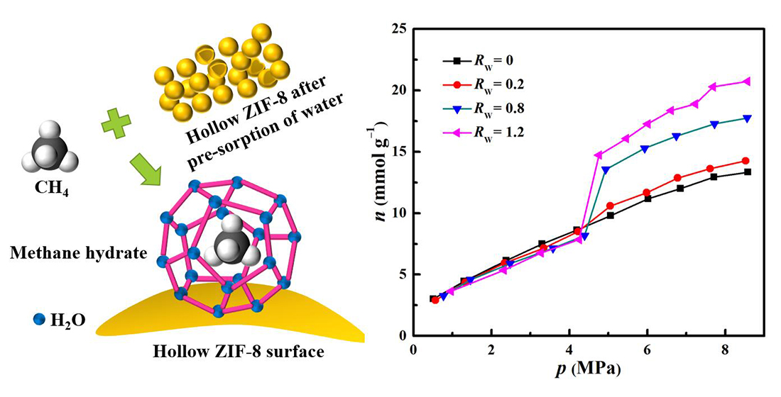
2.2. Methane Hydrate Formation in Hollow ZIF-8 Nanoparticles

The methane adsorption isotherms measured at 275 K for adsorbents obtained by pre-adsorbing different masses of water (RW = 0, 0.2, 0.8, and 1.2) on dry, hollow ZIF-8 are shown in Figure 5. RW stands for the mass ratio of pre-adsorbed water and dry hollow ZIF-8 nanoparticles. The adsorption capacity of methane (n) is represented as the amount of methane adsorbed per unit mass of dry, hollow ZIF-8 nanoparticles. According to the IUPAC classification, the adsorption of the dry, hollow ZIF-8 nanoparticles exhibited a type I isotherm, and the adsorption amount gradually increased until saturation at 8–9 MPa, with a maximum adsorption amount of 13.32 mmol/g at 8.58 MPa. The reason for such high adsorption capacity, in addition to the promotion of methane adsorption by the methyl group in the organic ligand [29], may be that the hollow structure provides high pore volume to increase the adsorption capacity of methane. Notably, the methane adsorption isotherms for adsorbents with pre-adsorbed water no longer had the characteristics of type I isotherms, and there was a jump at about 4–5 MPa. When the pressure was less than the jumping pressure, the methane adsorption isotherm of the pre-adsorbed water sample almost coincided with the adsorption isotherm of the dry sample. This phenomenon is caused by the hydrophobic surface properties of ZIF-8, where water is completely repelled by the internal hydrophobic cavity, and the pores are not blocked, making the entire pore fully available for adsorption of methane molecules. At the jumping point, the amount of methane gas adsorbed on the sample rose sharply, corresponding to the generation of a large amount of methane gas hydrate. With RW of 0.8, the storage capacity of methane was 17.74 mmol/g. The storage capacity of methane gradually increased with the increase in pre-adsorbed water mass, and the maximum storage capacity of methane was 20.72 mmol/g when RW was 1.2, which raised the methane storage capacity by 55.6% more than the dry, hollow ZIF-8 nanoparticles, indicating that higher pre-sorption water mass could greatly increase the storage capacity of methane on the hollow ZIF-8 nanoparticles. The above results demonstrate that hollow ZIF-8 nanoparticles are conducive to achieving high methane storage capacity.
To study the generation rate at the jump point of the methane adsorption isotherm on the hollow ZIF-8 nanoparticles, the methane pressure values with time were recorded at 275 K, when RW was 0.8 and 1.2, respectively. The corresponding curves were made as shown in Figure 6. When RW was 0.8, the induction time of the methane hydrate formation at 275 K was 3.5 h. With the increase in RW to 1.2, the induction time of the methane hydrate formation further increased to 4.75 h. In addition, it could be observed that the methane growth rate on hollow ZIF-8 nanoparticles was faster at RW of 0.8 than that at RW of 1.2. The process of hydrate generation took 5 h to reach equilibrium when RW was 0.8. With RW of 1.2, although the equilibrium adsorption capacity of the methane was remarkably improved (Figure 5), the time to reach the equilibrium pressure increased significantly and reached about 7 h. This may be because the increase in water mass made a considerable thickness of the water layer accumulate on the surface of the hollow ZIF-8 nanoparticles, which is very unfavorable for the diffusion of gas from the gas-solid interface to the porous surface. As a result, methane could not quickly reach the pores favorable for hydrate generation, and the rate of hydrate generation was greatly reduced. Hollow ZIF-8 nanoparticles with RW of 1.2 could obtain a slightly higher storage capacity for methane and a slower nucleation and growth kinetics than that at RW of 0.8. Taking these two factors into account, RW for subsequent methane adsorption experiments on hollow ZIF-8 nanoparticles with pre-adsorbed water was set to 0.8. The methane adsorption experiment was conducted in pure water, but in the absence of hollow ZIF-8 nanoparticles. There was no occurrence of methane adsorption (>12 h), demonstrating the promotion effect of the hollow ZIF-8 nanoparticles on methane hydrate formation. In addition to a large number of contact sites between water and methane provided by the hollow ZIF-8 nanoparticles, the hydrophobic surface of ZIF-8, which promotes the formation of hydrogen, bonded to facilitate the growth of methane hydrate. Furthermore, a large number of the adsorbed methane molecules in the pores of the hollow ZIF-8 were partially moved to the outside surface of the hollow ZIF-8 to expedite the hydrate growth [30]. Therefore, hollow ZIF-8 nanoparticles play a catalytic role to promote methane hydrate formation.

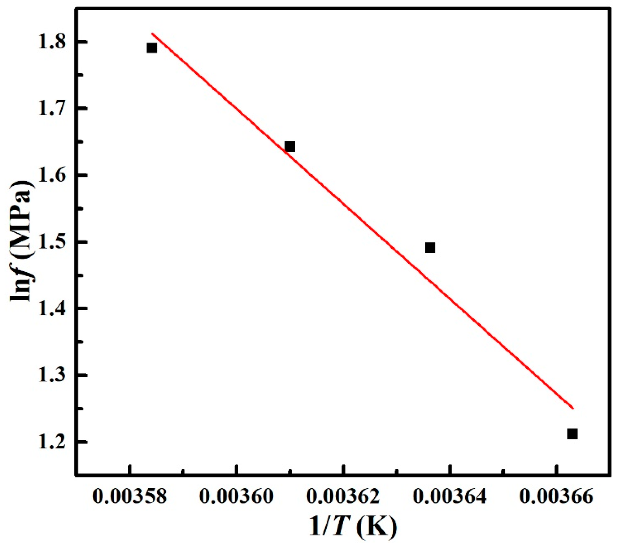
2.3. Formation Enthalpy of Methane Hydrate in Hollow ZIF-8 Nanoparticles

To further demonstrate that the increase in methane storage in the wet, hollow ZIF-8 nanoparticles results from the generation of methane hydrate, the adsorption isotherms of methane in wet, hollow ZIF-8 (RW = 0.8) at four temperatures were performed. As shown in Figure 7, as the temperature increased, the pressure at the jump point gradually increased. Before jumping in pressure, the methane adsorption capacity at different temperatures was almost the same. After the jumping pressure, the methane storage capacity showed a decreasing trend along with the temperature. The above results suggest that the temperature has a significant influence on methane hydrate formation pressure and the equilibrium adsorption capacity of methane. The increased temperature is not conducive to methane storage, which is consistent with the properties of methane hydrate.
According to the Clausius–Clapeyron equation (1), the enthalpy of methane hydrate generation (ΔHform) can be calculated from the jump pressures corresponding to the different temperatures based on the methane adsorption isotherms at 273 K, 275 K, 277 K, and 279 K in the wet, hollow ZIF-8 material (RW = 0.8):
d p d T = Δ H T Δ V
where ∆H is the molar enthalpy of phase change, ∆V is the molar volume change caused by the phase change, and R is the gas constant 8.314 J·mol−1 K−1. For the actual gas, the pressure (p) is replaced by the fugacity (ƒ), which is related to p and temperature (T). Equation (1) is transformed as follows:
d f d T = Δ H form T Δ V
Because the experimental temperatures are above 273 K, and water exists in the liquid state before hydrate generation, the generation of methane hydrate can be expressed by Equation (3):
C H 4 ( gas ) + n H 2 O ( liquid ) C H 4 · n H 2 O ( solid )
From the equation, it can be seen that the methane hydrate generation and decomposition reaction is a two-component and three-phase system. The change in the molar volume in the hydrate generation process is
Δ V = V C H 4 · n H 2 O ( solid ) V C H 4 ( gas ) V H 2 O ( liquid ) V C H 4 ( gas ) = R T f
where ΔH is assumed to be a constant that does not vary with T. Equation (4) taken into Equation (2) can be deformed into the Equation (5):
ln f = ± Δ H R T + C 1 ( constant )
The formula (5) for calculating the enthalpy change from the formation reaction is the sign (+); the formula (5) for calculating the enthalpy change from the decomposition reaction is the sign (−).
According to the definition of fugacity, there is
f = p × ϕ
The relationship between the fugacity factor ϕ and the compression factor Z is
ln ϕ = 0 p ( Z 1 ) p d p
According to the methane hydrate generation pressure corresponding to the methane adsorption isotherm at different temperatures, ϕ is calculated from Equation (7), and then f is calculated from Equation (6). The results of methane hydrate generation p, ϕ, and ƒ at different temperatures are shown in Table 2.
The fitting plot of lnƒ versus reciprocal temperature is shown in Figure 8. From Equation (5), the slope of the fitting line in Figure 8 is ΔHform/R. The calculated enthalpy of the generation reaction on the wet, hollow ZIF-8 nanoparticles is −59.22 kJ/mol, and the negative sign represents the exothermal process. This is essentially the same as the enthalpy of the formation of methane hydrate in pure water (−59.5 kJ/mol). Therefore, it is very reasonable to infer that methane hydrate is formed on the wet, hollow ZIF-8 nanoparticles.

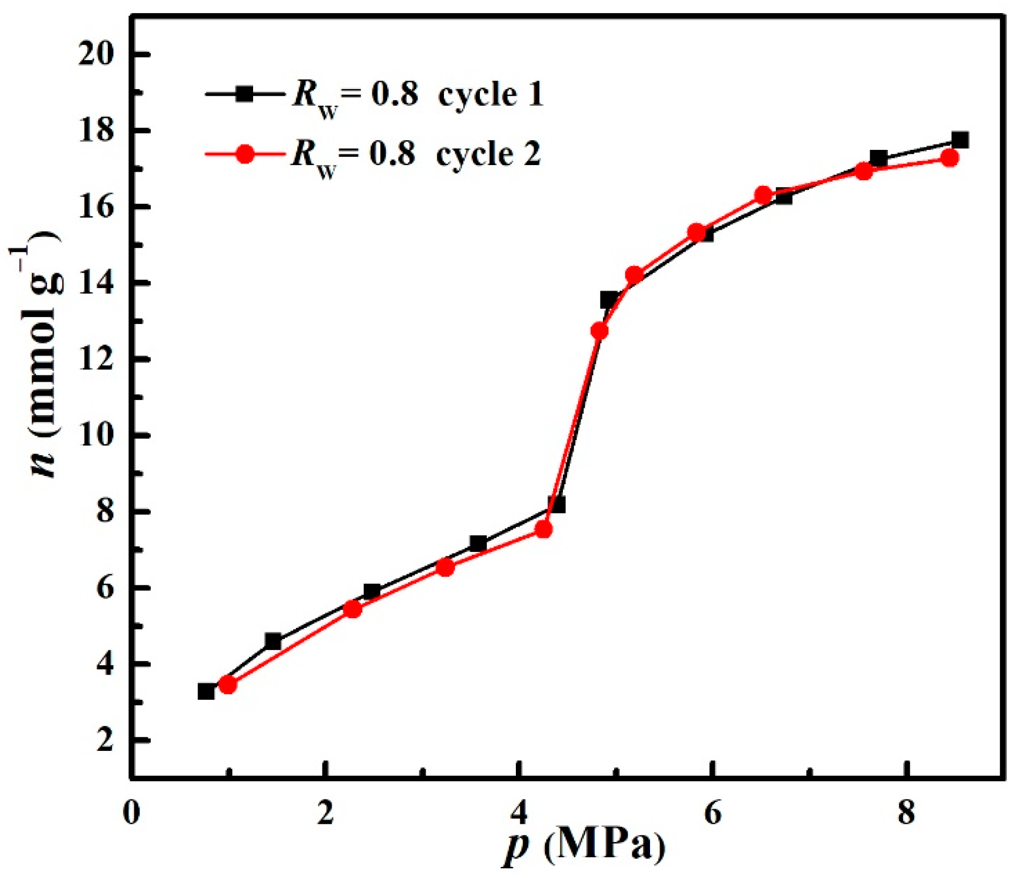
2.4. Stability of Hollow ZIF-8 Nanoparticles

To check the stability of the hollow ZIF-8 nanoparticles, the wet, hollow ZIF-8 nanoparticles with RW of 0.8 were used as an absorbent to conduct repeated methane adsorption experiments at 275 K. As shown in Figure 9, the jump point in the adsorption isotherm in the second cycle was essentially the same as in the first cycle, and the storage capacity of methane on the wet, hollow ZIF-8 nanoparticles was almost unchanged. The above results demonstrate that hollow ZIF-8 nanoparticles could be recyclable, which might be ascribed to the hydrophobicity and water stability of ZIF-8.

3. Materials and Methods

3.1. Materials

Styrene (99%) and 2-methylimidazole (98%) were supplied by Aladdin. Sodium styrene sulfonate (98%), sodium bicarbonate (99.99%), and potassium persulfate (99.5%) were purchased from Macklin. Methanol anhydrous (99.8%), zinc nitrate hexahydrate (99%), and N, N-dimethylformamide (99.5%) were purchased from Kermel. Styrene of chemical reagent grade was distilled under vacuum before use.

3.2. Preparation of PS Microspheres

Homogeneous PS colloidal microspheres were synthesized by the surfactant-free emulsion polymerization method [31]. The specific process is as follows: First, 0.0217 g of sodium styrene sulfonate and 0.1082 g of sodium bicarbonate were dissolved in 200 mL of distilled water in a round bottom flask at 80 °C under stirring for 10 min. Then, 21.6450 g of styrene was added. After stirring for 1 h, 0.1082 g of potassium persulfate was added. The reaction was allowed to proceed for 18 h under a nitrogen atmosphere with magnetic stirring at 350 rpm.

3.3. Preparation of Hollow ZIF-8 Nanoparticles

PS@ZIF-8 core–shell nanoparticles were prepared by the hard template method. First, 0.0600 g of Zn(NO3)2·6H2O and 0.0300 g of PS microspheres were mixed in 16 mL of methanol, and then 0.1660 g of 2-methylimidazole was added, followed by sonication for 1 min. The resulting mixture was heated in a water bath at 70 °C for 30 min. Subsequently, the reaction mixture was cooled naturally to room temperature, and the products were collected by centrifugation, washed, and dried. Due to the mass difference, the pure nanosized ZIF-8 nanoparticles were separated from the core–shell nanoparticles during the preparation process by adjusting the centrifugation speed. The PS@ZIF-8 core–shell nanoparticles were immersed in DMF solvent to remove the PS template, and the obtained hollow ZIF-8 nanoparticles were dried at 70 °C for 12 h.

3.4. Characterizations

A Bruker D8 Focus Powder X-ray diffractometer (XRD) from Germany was used to characterize the crystalline phase of the products. A Nova Nano SEM450 field emission scanning electron microscope (SEM) and a Talos F200S field emission transmission electron microscope (TEM) from the USA were used to observe the morphology of the products. The specific surface area, pore structure, and pore size of the samples were determined using an ASAP 2020 specific surface and porosity analyzer produced by Micromeritics in the USA. Based on the 77 K nitrogen adsorption equilibrium data, the specific surface area was calculated by the Brunauer–Emmett–Teller (BET) method, and the pore size distribution was calculated by the Barret–Joyner–Halenda (BJH) method. The removal of PS was analyzed using a V80X FTIR spectrometer manufactured by Bruker, Germany, and pressed into tablets using a tablet press for determination.

3.5. Methane Adsorption Measurements

The methane adsorption test was carried out by the volumetric method, and the corresponding apparatus is shown in Figure 10 [32,33]. The temperature fluctuation range of the thermostatic bath was ±0.1 °C. The pressure sensor had a pressure range of 0–20 MPa and an accuracy of 0.05%. The pressure range of the test was 0–10 MPa. Before measuring the adsorption by volumetric method, the sample was heated to 100 °C, and then degassed under vacuum at 100 °C for 12 h. The entire system was vacuumed, and the adsorption tank containing the wet sample needed to be cooled at −10 °C for 1 h before each vacuuming to reduce the moisture loss of wet samples during the vacuuming. The calculation of n is described in Ref [32].

4. Conclusions

Hollow-structured ZIF-8 with a high specific surface area was prepared by the hard template method. The synthesized hollow-ZIF-8 nanoparticles could promote the formation of methane hydrate. The pre-adsorbed water mass has a significant influence on the methane storage capacity. With an increase in RW, the methane storage capacity on the hollow ZIF-8 nanoparticles shows a gradually increasing tendency. The maximum storage capacity of methane is 20.72 mmol/g on the wet, hollow ZIF-8 nanoparticles with RW of 1.2 at 275 K and 8.57 MPa, which increases the methane storage capacity by 55.6% more than the dry, hollow ZIF-8 nanoparticles under the same condition. Compared with the methane formation process on the hollow ZIF-8 nanoparticles with RW of 1.2, the hollow ZIF-8 nanoparticles with RW of 0.8 possess a shortened induction time of 3.5 h and an accelerated growth process. The calculated enthalpy of the generation reaction (−59.22 kJ/mol) on the wet, hollow ZIF-8 nanoparticles with RW of 0.8 is close to the formation enthalpy of the methane hydrate in pure water, demonstrating the formation of the methane hydrate in hollow ZIF-8 nanoparticles. Due to the hydrophobicity and water stability of ZIF-8, the hollow ZIF-8 nanoparticles could be recyclable. This work demonstrates that hollow ZIF-8 nanoparticles are a promising material for the wet storage of methane, which would be conducive to realizing the practical application of methane storage and transportation.

Supplementary Materials

The following supporting information can be downloaded at: https://www.mdpi.com/article/10.3390/catal12050485/s1, Figure S1: SEM images of PS@ZIF-8 nanoparticles synthesized for 10 min (a) and 30 min (b).; Figure S2: SEM images of PS@ZIF-8 nanoparticles synthesized by mixing the precursors first and then adding PS (a) and after removal of PS (b).

Author Contributions

Conceptualization, Y.L. and J.C.; methodology, C.C. and Y.L.; software, C.C.; validation, C.C., Y.L. and J.C.; formal analysis, Y.L.; investigation, C.C.; data curation, Y.L. and J.C.; writing—original draft preparation, C.C.; writing—review and editing, Y.L. and J.C.; visualization, C.C.; supervision, Y.L. and J.C.; project administration, Y.L.; funding acquisition, Y.L. All authors have read and agreed to the published version of the manuscript.

Funding

This work was funded by the Key Laboratory of Gas Hydrate, Guangzhou Institute of Energy Conversion, Chinese Academy of Sciences, China (No. E029kf1601), the National Natural Science Foundation of China (No. 22008049), and the Natural Science Foundation of Hebei Province, China (No. B2020202081).

Conflicts of Interest

The authors declare no conflict of interest.

References

  1. Huang, K.; Miller, J.B.; Huber, G.W.; Dumesic, J.A.; Maravelias, C.T. A General Framework for the Evaluation of Direct Nonoxidative Methane Conversion Strategies. Joule 2018, 2, 349–365. [Google Scholar] [CrossRef] [Green Version]
  2. Chong, Z.R.; Yang, S.H.B.; Babu, P.; Linga, P.; Li, X.-S. Review of Natural Gas Hydrates as an Energy Resource: Prospects and Challenges. Appl. Energy 2016, 162, 1633–1652. [Google Scholar] [CrossRef]
  3. Casco, M.E.; Silvestre-Albero, J.; Ramírez-Cuesta, A.J.; Rey, F.; Jordá, J.L.; Bansode, A.; Urakawa, A.; Peral, I.; Martínez-Escandell, M.; Kaneko, K.; et al. Methane Hydrate Formation in Confined Nanospace Can Surpass Nature. Nat. Commun. 2015, 6, 6432. [Google Scholar] [CrossRef] [PubMed] [Green Version]
  4. Bhattacharjee, G.; Goh, M.N.; Arumuganainar, S.E.K.; Zhang, Y.; Linga, P. Ultra-Rapid Uptake and the Highly Stable Storage of Methane as Combustible Ice. Energy Environ. Sci. 2020, 13, 4946–4961. [Google Scholar] [CrossRef]
  5. Veluswamy, H.P.; Kumar, A.; Kumar, R.; Linga, P. An Innovative Approach to Enhance Methane Hydrate Formation Kinetics with Leucine for Energy Storage Application. Appl. Energy 2017, 188, 190–199. [Google Scholar] [CrossRef]
  6. Sloan, E.D. Fundamental Principles and Applications of Natural Gas Hydrates. Nature 2003, 426, 353–359. [Google Scholar] [CrossRef] [PubMed]
  7. Mu, L.; Liu, B.; Liu, H.; Yang, Y.; Sun, C.; Chen, G. A Novel Method to Improve the Gas Storage Capacity of ZIF-8. J. Mater. Chem. 2012, 22, 12246–12252. [Google Scholar] [CrossRef]
  8. Cuadrado-Collados, C.; Mouchaham, G.; Daemen, L.; Cheng, Y.; Ramirez-Cuesta, A.; Aggarwal, H.; Missyul, A.; Eddaoudi, M.; Belmabkhout, Y.; Silvestre-Albero, J. Quest for an Optimal Methane Hydrate Formation in the Pores of Hydrolytically Stable Metal-organic Frameworks. J. Am. Chem. Soc. 2020, 142, 13391–13397. [Google Scholar] [CrossRef]
  9. Casco, M.E.; Zhang, E.; Grätz, S.; Krause, S.; Bon, V.; Wallacher, D.; Grimm, N.; Többens, D.M.; Hauß, T.; Borchardt, L. Experimental Evidence of Confined Methane Hydrate in Hydrophilic and Hydrophobic Model Carbons. J. Phys. Chem. C 2019, 123, 24071–24079. [Google Scholar] [CrossRef]
  10. Borchardt, L.; Casco, M.E.; Silvestre-Albero, J. Methane Hydrate in Confined Spaces: An Alternative Storage System. ChemPhysChem 2018, 19, 1298–1314. [Google Scholar] [CrossRef] [Green Version]
  11. Peng, Y.; Krungleviciute, V.; Eryazici, I.; Hupp, J.T.; Farha, O.K.; Yildirim, T. Methane Storage in Metal-organic Frameworks: Current Records, Surprise Findings, and Challenges. J. Am. Chem. Soc. 2013, 135, 11887–11894. [Google Scholar] [CrossRef] [PubMed] [Green Version]
  12. Silva, P.; Vilela, S.M.F.; Tomé, J.P.C.; Almeida Paz, F.A. Multifunctional Metal-organic Frameworks: From Academia to Industrial Applications. Chem. Soc. Rev. 2015, 44, 6774–6803. [Google Scholar] [CrossRef] [Green Version]
  13. Jimenez, D.F.; Moggach, S.A.; Wharmby, M.T.; Wright, P.A. Opening the Gate: Framework Flexibility in ZIF-8 Explored by Experiments and Simulations. J. Am. Chem. Soc. 2011, 133, 8900–8902. [Google Scholar] [CrossRef] [Green Version]
  14. Andrés, M.A.; Vijjapu, M.T.; Surya, S.G.; Shekhah, O.; Salama, K.N.; Serre, C.; Eddaoudi, M.; Roubeau, O.; Gascón, I. Methanol and Humidity Capacitive Sensors Based on Thin Films of MOF Nanoparticles. ACS Appl. Mater. Interfaces 2020, 12, 4155–4162. [Google Scholar] [CrossRef] [PubMed]
  15. Bavykina, A.; Kolobov, N.; Khan, I.S.; Bau, J.A.; Ramirez, A.; Gascon, J. Metal-organic Frameworks in Heterogeneous Catalysis: Recent Progress, New Trends, and Future Perspectives. Chem. Rev. 2020, 120, 8468–8535. [Google Scholar] [CrossRef] [Green Version]
  16. Casco, M.E.; Rey, F.; Jordá, J.L.; Rudić, S.; Fauth, F.; Martínez-Escandell, M.; Rodríguez-Reinoso, F.; Ramos-Fernández, E.V.; Silvestre-Albero, J. Paving the Way for Methane Hydrate Formation on Metal–Organic Frameworks (MOFs). Chem. Sci. 2016, 7, 3658–3666. [Google Scholar] [CrossRef] [Green Version]
  17. He, Z.; Zhang, K.; Jiang, J. Formation of CH4 Hydrate in a Mesoporous Metal-organic Framework MIL-101: Mechanistic Insights from Microsecond Molecular Dynamics Simulations. J. Phys. Chem. Lett. 2019, 10, 7002–7008. [Google Scholar] [CrossRef] [PubMed]
  18. Denning, S.; Majid, A.A.; Lucero, J.M.; Crawford, J.M.; Carreon, M.A.; Koh, C.A. Metal-organic Framework HKUST-1 Promotes Methane Hydrate Formation for Improved Gas Storage Capacity. ACS Appl. Mater. Interfaces 2020, 12, 53510–53518. [Google Scholar] [CrossRef]
  19. Denning, S.; Majid, A.A.; Lucero, J.M.; Crawford, J.M.; Carreon, M.A.; Koh, C.A. Methane Hydrate Growth Promoted by Microporous Zeolitic Imidazolate Frameworks ZIF-8 and ZIF-67 for Enhanced Methane Storage. ACS Sustain. Chem. Eng. 2021, 9, 9001–9010. [Google Scholar] [CrossRef]
  20. Lai, X.; Halpert, J.E.; Wang, D. Recent Advances in Micro-/Nano-Structured Hollow Spheres for Energy Applications: From Simple to Complex Systems. Energy Env. Sci. 2012, 5, 5604–5618. [Google Scholar] [CrossRef]
  21. Chen, M.; Ye, C.; Zhou, S.; Wu, L. Recent Advances in Applications and Performance of Inorganic Hollow Spheres in Devices. Adv. Mater. 2013, 25, 5343–5351. [Google Scholar] [CrossRef]
  22. Zhang, X.F.; Liu, Y.G.; Li, S.H.; Kong, L.Y.; Liu, H.O.; Li, Y.S.; Han, W.; Yeung, K.L.; Zhu, W.D.; Yang, W.S.; et al. New Membrane Architecture with High Performance: ZIF-8 Membrane Supported on Vertically Aligned ZnO Nanorods for Gas Permeation and Separation. Chem. Mater. 2014, 26, 1975–1981. [Google Scholar] [CrossRef]
  23. Lee, H.J.; Cho, W.; Oh, M. Advanced Fabrication of Metal-organic Frameworks: Template-Directed Formation of Polystyrene@ZIF-8 Core-shell and Hollow ZIF-8 Microspheres. Chem. Commun. 2012, 48, 221–223. [Google Scholar] [CrossRef] [PubMed]
  24. Hutchinson, J.W. Imperfection Sensitivity of Externally Pressurized Spherical Shells. J. Appl. Mech. 1967, 34, 49–55. [Google Scholar] [CrossRef] [Green Version]
  25. Shan, A.X.; Chen, Z.C.; Li, B.Q.; Chen, C.P.; Wang, R.M. Monodispersed, Ultrathin NiPt Hollow Nanospheres with Tunable Diameter and Composition via a Green Chemical Synthesis. J. Mater. Chem. A 2015, 3, 1031–1036. [Google Scholar] [CrossRef]
  26. Pan, Y.C.; Liu, Y.Y.; Zeng, G.F.; Zhao, L.; Lai, Z.P. Rapid Synthesis of Zeolitic Imidazolate Framework-8 (ZIF-8) Nanocrystals in an Aqueous System. Chem. Commun. 2011, 47, 2071–2073. [Google Scholar] [CrossRef]
  27. Yang, Y.F.; Wang, F.W.; Yang, Q.H.; Hu, Y.L.; Yan, H.; Chen, Y.Z.; Liu, H.R.; Zhang, G.Q.; Lu, J.L.; Jiang, H.L.; et al. Hollow Metal–Organic Framework Nanospheres via Emulsion-Based Interfacial Synthesis and Their Application in Size-Selective Catalysis. ACS Appl. Mater. Interfaces 2014, 6, 18163–18171. [Google Scholar] [CrossRef] [PubMed]
  28. Zhang, J.Q.; Li, L.; Xiao, Z.X.; Liu, D.; Wang, S.; Zhang, J.J.; Hao, Y.T.; Zhang, W.Z. Hollow Sphere TiO2–ZrO2 Prepared by Self-Assembly with Polystyrene Colloidal Template for Both Photocatalytic Degradation and H2 Evolution from Water Splitting. ACS Sustain. Chem. Eng. A 2016, 4, 2037–2046. [Google Scholar] [CrossRef]
  29. Sumida, K.; Rogow, D.L.; Mason, J.A.; McDonald, T.M.; Bloch, E.D.; Herm, Z.R.; Long, J.R.; Bae, T.-H. Carbon Dioxide Capture in Metal-organic Frameworks. Chem. Rev. 2012, 112, 724–781. [Google Scholar] [CrossRef]
  30. Wang, Z.; Duan, J.; Chen, S.; Fu, Y.; Zhang, Y.; Wang, D.; Pei, J.; Liu, D. Molecular Insights into Hybrid CH4 Physisorption-Hydrate Growth in Hydrophobic Metal-organic Framework ZIF-8: Implications for CH4 Storage. Chem. Eng. J. 2022, 430, 132901. [Google Scholar] [CrossRef]
  31. Im, S.H.; Lim, Y.T.; Suh, D.J.; Park, O.O. Three-Dimensional Self-Assembly of Colloids at a Water-Air Interface: A Novel Technique for the Fabrication of Photonic Bandgap Crystals. Adv. Mater. 2002, 14, 1367–1369. [Google Scholar] [CrossRef]
  32. Zhou, L.; Sun, Y.; Zhou, Y. Enhancement of the Methane Storage on Activated Carbon by Preadsorbed Water. AIChE J. 2002, 48, 2412–2416. [Google Scholar] [CrossRef]
  33. Zhou, L.; Liu, X.; Sun, Y.; Li, J.; Zhou, Y. Methane Sorption in Ordered Mesoporous Silica SBA-15 in the Presence of Water. J. Phys. Chem. B 2005, 109, 22710–22714. [Google Scholar] [CrossRef] [PubMed]
Figure 1. SEM images of PS (a) and PS@ZIF-8 (b); SEM (c) and TEM(d) images of hollow ZIF-8 particles.
Catalysts 12 00485 g001
Figure 2. XRD patterns of ZIF-8, PS@ZIF-8, and hollow ZIF-8 particles with the simulated XRD pattern from the crystallographic data of ZIF-8.
Catalysts 12 00485 g002
Figure 3. FTIR spectra of PS microspheres, ZIF-8, PS@ZIF-8, and hollow ZIF-8 particles.
Catalysts 12 00485 g003
Figure 4. N2 adsorption−desorption isotherms of PS@ZIF-8 and hollow ZIF-8 particles (a) with the corresponding pore size distribution (b).
Catalysts 12 00485 g004
Figure 5. Methane adsorption isotherms of hollow ZIF-8 nanoparticles with different amounts of pre-adsorbed water at 275 K.
Catalysts 12 00485 g005
Figure 6. Dynamic curves of methane adsorption on the wet, hollow ZIF-8 nanoparticles with different amounts of pre-adsorbed water.
Catalysts 12 00485 g006
Figure 7. Methane adsorption isotherms of hollow ZIF-8 nanoparticles (RW = 0.8) at different temperatures.
Catalysts 12 00485 g007
Figure 8. Linear fit of lnƒ with 1/T.
Catalysts 12 00485 g008
Figure 9. Methane adsorption isotherms at 275 K in the wet, hollow ZIF-8 with RW of 0.8 after different cycles.
Catalysts 12 00485 g009
Figure 10. Experimental apparatus of methane adsorption: a—methane cylinder; b—vacuum pump; c—vent; d—reference tank in a thermostatic bath; e—adsorption tank in a low-temperature bath; V1, V2, V4, V5, V79—cutoff valve; V3, V6—metering valve; M1, M2—pressure gauge; M3—pressure sensor.
Catalysts 12 00485 g010
Table 1. Physical characterizations of PS@ZIF-8 and hollow ZIF-8 nanoparticles.
SampleSBET (m2/g)V (cm3/g)
PS@ZIF-8518.82390.3187
hollow ZIF-81260.92720.8250
Table 2. State data of the jump pressure at different temperatures.
T (K)p (MPa)ϕlnƒ
2733.610.93031.2115
2754.930.90071.4907
2775.870.88031.6424
2796.980.85831.7902
Publisher’s Note: MDPI stays neutral with regard to jurisdictional claims in published maps and institutional affiliations.

