Article

Sustainable Synthesis of a Highly Stable and Coke-Free Ni@CeO2 Catalyst for the Efficient Carbon Dioxide Reforming of Methane

1
Graduate School of Energy Science and Technology, Chungnam National University, 99 Daehak-ro, Yuseong-gu, Daejeon 34134, Korea
2
Department of Chemistry, School of Science, South Valley University, Qena 83523, Egypt
3
Organic Nanomaterials Lab, Department of Chemistry, Hannam University, Daejeon 34054, Korea
*
Authors to whom correspondence should be addressed.
These authors contributed equally to this work.
Catalysts 2022, 12(4), 423; https://doi.org/10.3390/catal12040423
Submission received: 2 March 2022 / Revised: 2 April 2022 / Accepted: 6 April 2022 / Published: 9 April 2022
(This article belongs to the Special Issue Research Progress of Reforming Catalysts)

Abstract

:
A facile and green synthetic strategy is developed in this paper for the construction of an efficient catalyst for the industrially important carbon dioxide reforming of methane, which is also named the dry reforming of methane (DRM). Through controlling the synthetic strategy and Ni content, a high-performance Ni@CeO2 catalyst was successfully fabricated. The catalyst showed superb efficiency for producing the syngas with high and stable conversions at prolonged operating conditions. Incorporating Ni during the ceria (CeO2) crystallization resulted in a more stable structure and smaller nanoparticle (NP) size with a more robust interaction with the support than loading Ni on CeO2 supports by the conventional impregnation method. The H2/CO ratio was almost 1.0, indicating the promising applicability of utilizing the obtained syngas for the Fischer–Tropsch process to produce worthy chemicals. No carbon deposits were observed over the as-synthesized catalyst after operating the DRM reaction for 50.0 h, even at a more coke-favoring temperature (700 °C). Owing to the superb resistance to coke and sintering, control of the size of the Ni-NPs, uniform dispersion of the active phase, and potent metal interaction with the support, the synthesized catalyst achieved a magnificent catalytic activity and durability during serving for the DRM reaction for extended operating periods.

1. Introduction

Despite significant efforts toward widespread renewable energy systems, traditional fossil fuels remain the essential energy source [1]. The combustion of these fuels releases tremendous amounts of carbon dioxide (CO2) into the atmosphere, resulting in universal warming and climate change [2,3]. Another paramount contributor to global warming is methane (CH4) [4], which is produced from petroleum reserves and landfill gas [5]. Converting CH4 and CO2 into valuable chemicals is one of the best routes to alleviate anthropogenic climate change. In terms of this concern, dry reforming of methane (DRM) is a fascinating, environmentally friendly process where it transforms two crucial greenhouse gases into syngas (a mixture of CO and H2) according to the following reaction: [6,7].
CH4 + CO2 → 2CO + 2H2, ΔH0298K = +247 kJ mol−1
The syngas is a precious chemical building block for producing very important compounds via the Fischer–Tropsch (FT) reaction [6,8]. Another technology for converting CH4 into syngas is the steam reforming of methane (SRM) [9]; however, DRM has considerable merits compared to SRM [10]. For example, the DRM produces an equal molar ratio of H2/CO, which fulfills the necessity for FT reaction to produce valuable chemicals [3,11]. In addition, biogas can be directly used as a feedstock for the DRM, and hence eschews the complication and high cost of separating CO2 [1]. More importantly, DRM consumes two major greenhouse gases in a single step—consequently, it plays a vital role in reducing the harmful effects of these two gases [12].,
Noble metals such as platinum (Pt) and ruthenium (Ru) have the best ability to crack C–H bonds and the highest resistance to coke deposition [6,8,10]; nevertheless, the high cost of noble metals impedes their industrial application for the DRM process. Ni-based catalysts showed comparable catalytic activity towards the DRM reaction. Their level of performance, affordability, and abundance make them the most suitable catalysts for the DRM [3,12,13]. Unfortunately, Ni-based catalysts still encounter hurdles in commercial implementation because the quick deactivation originated from the critical sintering of the active phase (Ni) at high temperatures and coke formation [7,14]. The decomposition of methane (CH4 → Cads + 2H2) and disproportionation of carbon monoxide (2CO → Cads + CO2) are the main sources of coke formation [8,15,16]. As a result, developing efficient noble-metal-free catalysts of high resistance against sintering and carbon deposition during the DRM process remains a significant challenge. Various metal oxides have been utilized for supporting Ni, including alumina (Al2O3), silica (SiO2), ceria (CeO2), zirconia (ZrO2), or a mixture of two or more of these oxides [17,18,19,20,21,22,23,24,25,26,27]. The objective of using a support for Ni is to enhance the surface area and improve the durability of Ni [28]. The nature of the support remarkably influences the catalytic activity and stability of Ni towards the DRM reaction [3,29,30].
The bi-functional mechanism is widely accepted for explicating the high stability of Ni-supported catalysts [31,32], where CH4 is activated by Ni-NPs and CO2 by the support. In this regard, the support must have some basic characteristics to adsorb CO2, whereas Ni-NPs should be as small as possible, highly dispersed and strongly interacted with the support. CeO2 is among the various kinds of supports that attracted much attention because of its unique redox characteristics, stupendous oxygen storage/release capacity, and basic property [12,13,32]. The contemporaneous reduction of Ce4+ to Ce3+ results in creating oxygen vacancies in CeO2 [13]. The generated oxygen vacancies improve the adsorption and dissociation of CO2 [33].
During the DRM reaction, CO2 could be activated to the mobile oxygen in the oxygen vacancy site in CeO2, and the mobile oxygen could be applied to detach carbon from the catalyst’s surface [32,34], hence prohibiting the growth or accumulation of the inert carbonaceous species, therefore overcoming the issue of carbon deposition, which is the main challenge for the DRM process. Furthermore, the robust metal-support interaction on Ni/CeO2 was proven to significantly upgrade the catalytic performance of Ni towards the dissociation of CH4, where its activation barrier lessened from 0.90 eV on Ni (111) to 0.15 eV on Ni/CeO2–x (111) [32,35,36]. Combining the synergistic effect of the oxygen ion conductivity of CeO2 and its capability of reducing the activation barrier of CH4, it appears that Ni-supported CeO2 will be a good catalyst for catalyzing the DRM reaction. Unluckily, exposure to reducing environments at high temperatures usually drives the segregation of CeO2 and inhomogeneous distribution of Ni [37]. Accordingly, large Ni clusters are formed, which accelerate coke formation and, therefore, quickly deactivate the catalyst. As a result of the thermal instability of CeO2, it is rarely used as pure support for Ni in the DRM process when the reaction is performed at high temperatures (≥600 °C). Instead, it has been utilized as a promotor or combined with other thermally stable supports like Al2O3 [38,39], ZrO2 [17,37,40,41], or SiO2 [32,42,43], which makes the synthetic methods more tedious and interpreting the catalytic activity and durability more complicated. Consequently, alternative approaches are required to fabricate stable Ni/CeO2-based catalysts with uniform dispersion and small size of the NPs.
The interface between Ni and CeO2 is crucial for catalytic activity and stability [31,32]. It has been demonstrated that: the closer the interaction and contact between Ni and CeO2 on SiO2, the higher the catalytic activity towards the DRM since the more interfacial contact between Ni and CeO2 improves the synchronous activation of CH4 and CO2 [32]. Besides, the close contact between Ni and CeO2 supplies more reactive oxygen species and more interfacial sites, which are highly advantageous for the fast gasification of the carbonaceous species formed during the DRM reaction, hence maintaining durable activity in long-term reactions [32]. When the Ni-NPs were far from the CeO2 on SiO2, the catalytic activity decreased due to the less interfacial interaction between Ni and CeO2. So, what if a catalyst consists only of Ni and CeO2 without the thermally stable SiO2, where the interfacial contact between Ni and CeO2 could be at a maximum? It is expected that the catalytic activity would be promising because of the advantageous characteristics of the CeO2 mentioned above. However, the thermal instability of CeO2 may lead to the sintering of Ni-NPs and therefore deteriorate its performance. Accordingly, an approach must be developed to fabricate a Ni/CeO2-based catalyst where the high temperature does not affect the dispersion of Ni, i.e., it does not drive to sintering of the active phase, and hence the catalytic activity could be stable during the operation of the DRM reaction for long-term periods.
In this regard, we herein developed a novel and scalable synthetic strategy for fabricating an efficient Ni-based catalyst for the DRM reaction using only CeO2 as pure support. The active phase (Ni-NPs) remained highly dispersed within the infrastructure of the support during the reduction process at 800 °C because of their confinement by the CeO2, which inhibits their sintering at high temperatures. We demonstrated that incorporating Ni into CeO2 during the crystal growth of CeO2 resulted in confining Ni-NPs by CeO2 and hence maintaining the Ni-NPs highly dispersed throughout the infrastructure of CeO2. The Ni proportion was altered up to 20 wt% to realize the optimum Ni content for the catalytic activity in the DRM process. Through the precise control of Ni content and synthetic strategy, a highly active and stable catalyst for syngas production by the DRM process has been developed. The catalyst showed excellent catalytic activity and durability towards the DRM reaction with CH4 and CO2 conversions of 88.9 and 91.9%, respectively, at a temperature of 800 °C. More importantly, it displayed zero coke formation after operating the DRM reaction for 50.0 h, even at a more coke-favoring temperature (700 °C). Considering the cost-effectiveness, high activity, and superb resistance for both sintering and coke, the current work may pave the way to the sustainable design of efficient DRM catalysts.

2. Results and Discussion

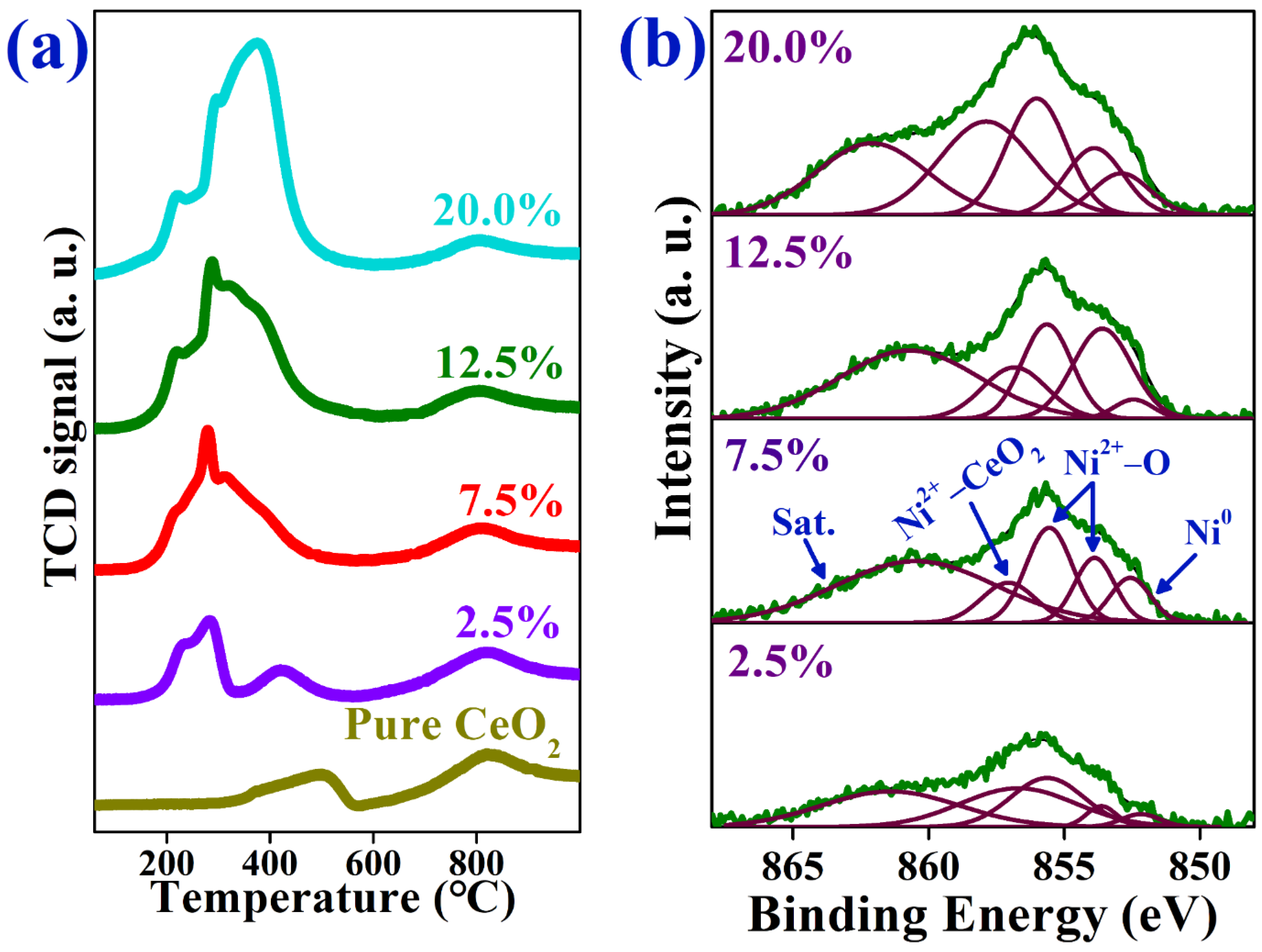
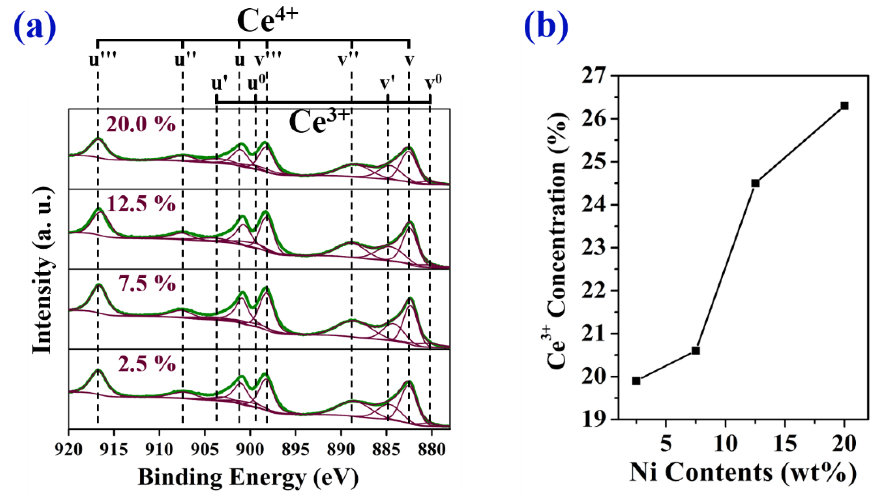
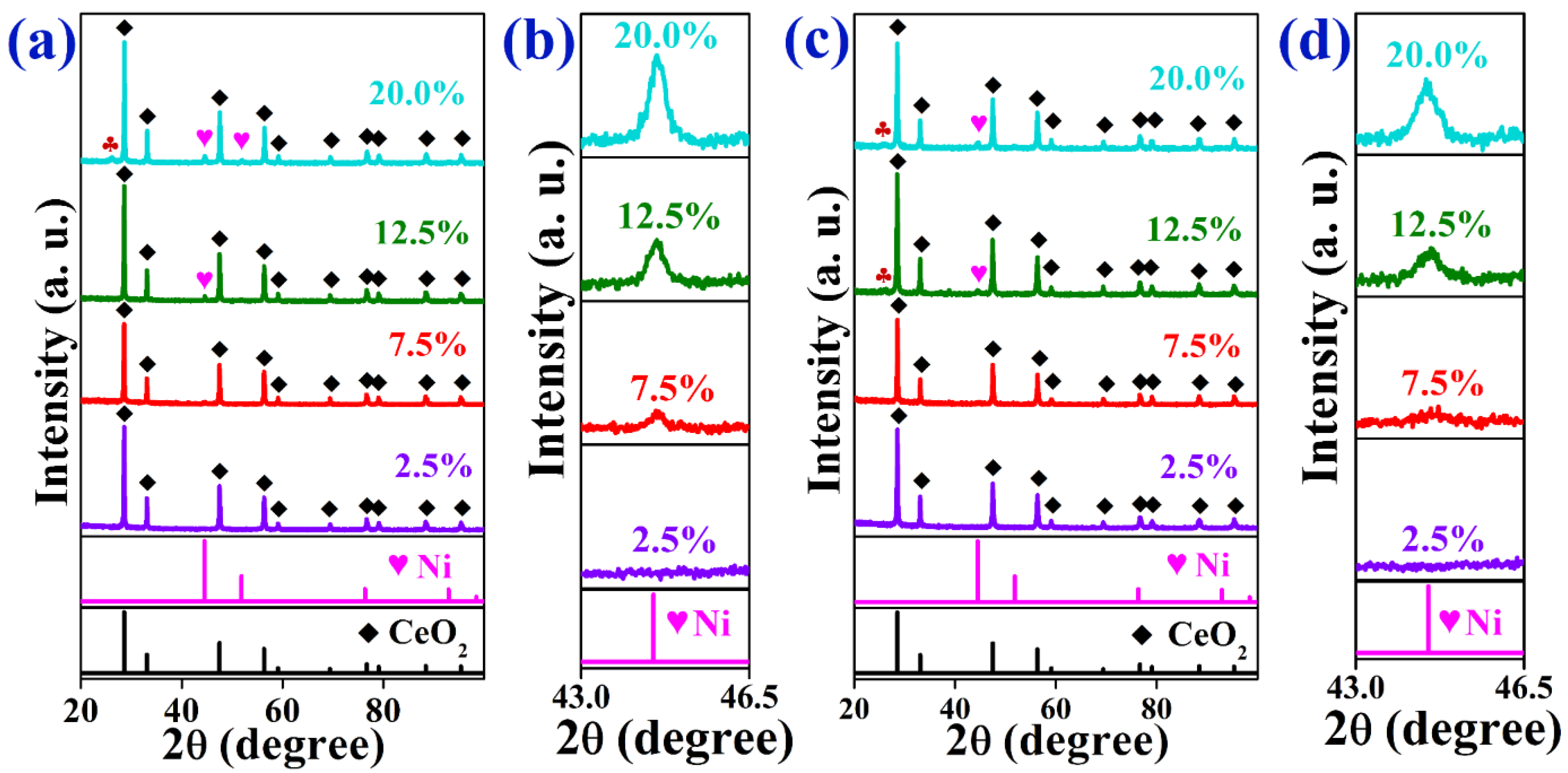
2.1. Characterization of As-Prepared Catalysts

Powder X-ray diffraction (PXRD) analysis was done to identify the crystal structure and type of the phases existing in the as-synthesized materials (Figure 1). The calcined samples fabricated by a one-pot strategy (Figure 1a) showed comparable diffractograms regardless of the Ni-loading. All peaks that appeared in the calcined materials are ascribed to the CeO2 phase (PDF#01-075-8371). The broadness of the diffractions peaks reflects the smaller size of the CeO2 support. The absence of the diffraction peaks related to the NiO phase in all prepared catalysts with Ni-loading up to 20 wt% indicates the superb dispersion of NiO NPs throughout the substructure of the CeO2 support, even at a high loading of Ni (20 wt%). The PXRD pattern of the calcined sample prepared by the impregnation method (Ni/CeO2/12.5/Impreg, Figure S1a) did not exhibit any clear peaks for the NiO phase. After reducing the calcined samples to 800 °C under an H2 atmosphere, the intensity of the diffraction peaks related to the CeO2 phase increased and became very sharp, indicating the enhancement of the materials’ crystallinity (Figure 1b). More importantly, there were no clear diffraction peaks for the Ni phase in all reduced catalysts, except for the Ni@CeO2/12.5 and Ni@CeO2/20, which showed a very small peak for Ni at 2θ of 44.63°. This assures that Ni-NPs were still highly dispersed throughout the CeO2 support, even after heating at a high temperature (800 °C). To calculate the size of Ni-NPs using the Scherer equation [44], we performed the PXRD at a slow scan rate (0.6°/min) in the 2θ range from 43.0 to 46.5 (Figure 1c). For Ni@CeO2/12.5 and Ni@CeO2/20 catalysts, the size of Ni-NPs was found to be 20.8 and 24.6 nm, respectively. When the Ni was post-impregnated to the CeO2 support, the diffraction peak related to Ni was more pronounced in the PXRD pattern (Figure S1b), indicating a lesser degree of dispersion within the support. This was confirmed by calculation of the NPs size, which was found to be 38.5 nm compared to 20.8 nm for the sample prepared by a one-pot strategy at the same loading of Ni (12.5 wt%). This observation shows the important role of the synthesis method in controlling the growth of the crystallite size of Ni-NPs at high reduction temperatures. The high dispersion and small size of Ni-NPs have vital roles in minimizing the coke formation during the DRM reaction and hence maintaining the catalytic activity for prolonged periods [3].
Figure 2a,b displays the nitrogen adsorption—desorption and pore size distribution (PSD) profiles of the calcined catalysts. The adsorption–desorption isotherms show the characteristics of the type IV isotherm with an H3 hysteresis loop according to the IUPAC classification, suggesting the mesoporous structure of the calcined samples [45]. The Brunauer–Emmett–Teller (BET) theory was applied to calculate the surface area of the catalysts. The BET surface area (BET SA), total pore volume, and average pore diameter (d) of the as-synthesized materials are shown in Table S1. In the absence of Ni, the CeO2 support showed a BET SA and total pore volume of 57.9 m2 g–1 and 0.072 cm3 g–1, respectively. The addition of Ni to CeO2 increased the BET SA and total pore volume of the catalysts. At low loadings of Ni, the BET SA enhanced to 78.8 and 79.7 m2 g–1, and the total pore volume was 0.093 and 0.085 cm3 g–1 for Ni@CeO2/2.5 Ni@CeO2/7.5 catalysts, respectively. The increase in the BET SA by incorporating dopants into CeO2 was also noticed in the literature [46,47], which implies that the introduction of Ni ions into the crystal lattice of CeO2 inhibits the crystal growth, which results in increasing the BET SA and total pore volume. This shows that the Ni species are well-dispersed and strongly interact with the CeO2 support. The further addition of Ni into CeO2 led to a decrease in the BET SA and total pore volume, where the BET SA diminished to 66.9 and 58.5 m2 g–1, and the total pore volume to 0.073 and 0.057 cm3 g–1 for Ni@CeO2/12.5 and Ni@CeO2/20, respectively. This demonstrates that the Ni proportion influences the texture properties of Ni@CeO2 catalysts and hence their catalytic behaviors.
The existence of mesopores in the calcined samples was confirmed by the PSD profiles obtained from the desorption branches of the isotherms using the Barrett–Joyner–Halenda (BJH) method (Figure 2b). All as-prepared materials showed uniform PSD with ‘d’ ranging from 3.9 nm for Ni@CeO2/20 catalyst to 5 nm for bare CeO2 (Table S1). After the reduction process at 800 °C for 1.50 h, the BET SA and total pore volume of the as-synthesized materials significantly decreased, whereas ‘d’ greatly increased due to the agglomeration of CeO2 under the effect of high temperature (Tables S1 and S2). On increasing the Ni-loading, the BET SA decreased continuously, which may be due to the formation of larger Ni crystallites upon the further addition of Ni to CeO2. The total pore volume followed a similar trend as that of BET SA.
The PSD curves (Figure 2d) show that the reduced samples had pore diameters in both mesoporous (2–50 nm) and macroporous regions (˃50 nm). The macropores provide a quick channel for the reactants to reach the active sites on the support and rapid passage for the diffusion of products from the active sites to the catalyst’s external surface, hence improving the catalytic activity [48].
The morphology of the reduced Ni@CeO2/7.5 catalyst was investigated by TEM analysis. Figure 3a shows the TEM image, and Figure 3b represents the magnification for the selected area by the green rectangle in Figure 3a. Some of the Ni-NPs existing on the CeO2 support were highlighted by the dotted green circles in Figure 3b. The EDX mapping images of Ni@CeO2/7.5 show that Ni-NPs are wrapped with CeO2 support. This structure restricts the movement of the Ni-NPs [49], which is beneficial for enhancing their sintering resistance, and hence maintaining a good dispersion of the Ni-NPs during the DRM reaction. Figure 4 shows the TEM, HADDF-STEM, and EDX elemental mapping images of the Ni@CeO2/12.5 catalyst. It is clear that Ni-NPs are well-dispersed within the substructure of the CeO2 support. In addition, the EDX mapping images (Figure 4d–f) show that Ni-NPs are surrounded by the CeO2 support, where the vacancies in Ni element (Figure 4d) are occupied by Ce and O elements (Figure 4e,f). This confirms that the Ni-NPs are intertwined with CeO2, which has a crucial role in inhibiting the agglomeration of the Ni-NPs at high temperatures, at which the DRM reaction is performed and therefore preserves high catalytic activity for long periods of time.
The reduction behavior of the as-prepared catalysts was examined by the H2-TPR analysis to identify the interaction strength of metal species with the support [50]. Figure 5a shows the H2-TPR profiles of the calcined samples. The pure CeO2 displayed two broad peaks at low and high temperatures of about 500 and 819 °C, respectively. The two peaks pertain to the reduction of surface and bulk CeO2, respectively [51,52,53]. The dissimilarity in these two reduction temperatures is ascribed to the variation in the binding energy of oxygen bonded to cerium cations in the lattice of CeO2 [46,51]. The incorporation of Ni into the crystal lattice of pure CeO2 resulted in shifting the reduction temperature of the surface and bulk CeO2 to lower temperatures. Moreover, new peaks appeared at temperatures below 400 °C, which are attributed to the reduction of NiO bonded with the support of different binding energies [47]. The diminishment in the reduction temperature of CeO2 after incorporating Ni is due to the decrease in the particle size and the increase in the BET SA, as well as the pore volume (Table S1) of CeO2 upon the addition of Ni, which resulted in the facilitation of the diffusion of H2 within the substructure of CeO2, and the creation of more active sites for the adsorption of H2. Furthermore, the inclusion of Ni into CeO2 enhances the migration of mobile oxygen species from bulk to the surface, which are readily reducible at lower temperatures [47]. The increase in the peak areas related to the reduction of Ni species with increasing the Ni-loading is because of the increase in the quantity of H2 consumed in the reduction of Ni species.
The XPS analysis was conducted to provide information about the chemical environment and oxidation states of Ni species existing within the surface region of the reduced catalysts (Figure 5b). The Ni 2p3/2 spectra of the reduced catalysts show five peaks at binding energies of about 852.5, 853.8, 855.6, 856.9 and 860.9 eV. The peak at 852.5 eV is attributed to the metallic Ni; meanwhile, the multi-split peaks at 853.8 and 855.6 eV with satellite peaks at 860.9 eV are related to the NiO [49,54]. The formation of NiO is due to the oxidation of metallic Ni when the samples were exposed to air [54,55]. The core-level peak at 856.9 eV is attributed to the contribution of Ni2+ species bonded with ceria support (Ni–O–Ce) [54]. The interaction between Ni-NPs and support restricts the movement of the Ni-NPs and therefore inhibits the sintering phenomenon. As a result, the catalyst can tolerate high temperatures during serving for the DRM process.
It is obvious from Figure 5b that the intensities of the XPS peaks increase with increasing the content of Ni in the as-synthesized catalysts, elucidating the increase in Ni content within the surface region of the various catalysts, which is advantageous for the DRM reaction, where the reaction occurs more easily and quickly on the surface than on the bulk of the catalyst. As a result, the DRM performance improves with increasing the Ni content, where more active sites for catalyzing the DRM are created, as will be explained in the next sections. However, after a certain level of Ni, the Ni-NPs tend to sinter and form large NPs. This results in facilitating the formation of coke and hence deactivating the catalyst after short periods from starting the reaction. Therefore, adjusting the Ni content in the catalyst is fundamental for controlling its catalytic activity and durability.
Figure S2 shows the Ni 2p3/2 spectra of the catalysts prepared by one-pot and impregnated methods at the same loading of Ni (12.5 wt%). Although both catalysts possess the same total Ni content, the Ni/CeO2/12.5/Impreg catalyst showed higher intensity for the peaks related to the different Ni species, suggesting the high content of Ni in the surface region of that catalyst. Consequently, it is expected that the Ni/CeO2/12.5/Impreg catalyst will display higher catalytic performance than the Ni@CeO2/12.5 catalyst, where the former has more active sites on its surface than the latter. This was true where the Ni/CeO2/12.5/Impreg displayed a better DRM performance than the Ni@CeO2/12.5, as will be discussed later. However, the catalytic activity of the former catalyst deteriorated after only a few minutes as a result of the severe coke deposition, but that of the latter was stable during all of the measurement time (50.0 h). It can be concluded that the method of incorporating Ni-NPs into CeO2 support has a pivotal effect in controlling the substructure of the catalysts, especially the distribution of the active phase within the support, which has a vital role in the catalyst’s performance during the DRM process.
Figure 6a shows the Ce 3d spectra for the as-reduced catalysts. The peaks labeled as v and u can be ascribed to Ce 3d5/2 and Ce 3d3/2, respectively. The five peaks for Ce 3d5/2 are located at 880.5, 882.5, 884.3, 888.4, and 898.2 eV, and the other five peaks are centered at 899.5, 901.0, 903.9, 907.4, and 916.6 eV. The peaks denoted as v, v″, v‴, u, u″, and u‴ can be corresponded to Ce4+ of CeO2, while those marked as v0, v′, u0, and u′ can be attributed to the Ce3+ of Ce2O3 [56,57]. This represents the coexistence of Ce3+ and Ce4+. According to the literature, when Ni is added to CeO2, an oxygen vacancy with two electrons will be formed to compensate for the charge imbalance between Ce4+ and Ni2+, and thus, it leads to Ce3+ formation, which is one of the major components of determining catalytic activity toward the DRM reaction [57,58]. Figure 6b exhibits the concentration of Ce3+ in the as-reduced Ni@CeO2 catalyst with different Ni-loadings (2.5, 7.5, 12.5, and 20 wt%). This result shows the increase of Ce3+ concentration with an increase in the Ni contents. Interestingly, it is observed that the amount of Ce3+ is highly changed in the range from 7.5 to 12.5 wt% of Ni contents. Since Ce3+ is one of the crucial factors for the DRM reaction, it is expected that there will be a significant change in catalytic activity at this point.

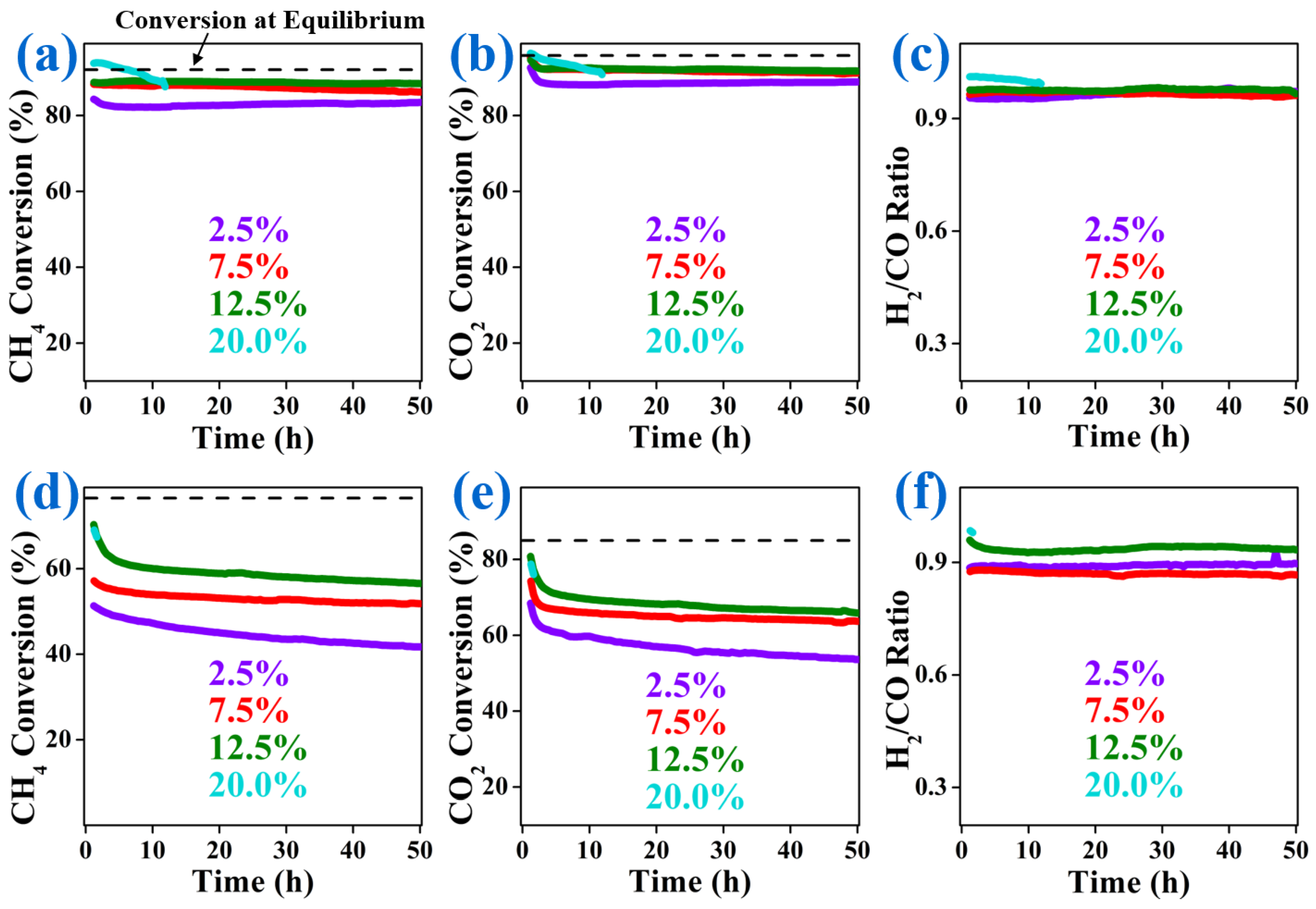
2.2. Catalytic Performance

The catalytic behaviors of Ni@CeO2 catalysts with different Ni-loadings towards the DRM reaction were investigated at temperatures of 700 and 800 °C, respectively. The obtained durability results are demonstrated in Figure 7, which explains the changes in the conversions of CH4 and CO2 and H2/CO molar ratios with time. Figure 7a–c show the catalytic conversions of CH4 and CO2, and the H2/CO ratio over the as-synthesized catalysts for 50.0 h at WHSV of 24,000 mL gcat–1 h–1, CH4/CO2 = 1.0, and temperature of 800 °C. All catalysts showed stable CH4 conversion during the DRM reaction for 50.0 h, except the Ni@CeO2/20 catalyst, where it showed a continuous decrease in the conversion with time and fully deactivated after only 11.0 h. As is clear from Figure 7a, the Ni@CeO2/12.5 catalyst displayed the best durability for the CH4 conversion, where it showed CH4 conversion efficiency of 88.6% after operating the DRM for 50.0 h, compared to 88.9% at the beginning of the reaction, indicating the excellent durability towards the DRM reaction, where there was almost no deterioration in the performance during the reaction for 50.0 h. Ni@CeO2/7.5 catalyst also showed admirable durability where it maintained 98.1% of its initial conversion efficiency after serving for the DRM reaction for 50.0 h. On the other hand, the Ni@CeO2/2.5 catalyst offered less catalytic performance than the aforementioned catalysts because of the smaller number of active sites, where its Ni content was only 2.5 wt%. Although the Ni@CeO2/20 catalyst presented the best initial CH4 conversion, its performance decreased gradually from 93.9 to 87.6% within 11.0 h. Then, the reactor was blocked due to the deactivation of the catalyst as a result of the much coke formed on its surface. The high initial conversion efficiency of the Ni@CeO2/20 catalyst is due to the high Ni-loading, which provides more catalytic active sites for catalyzing the DRM reaction. However, the high Ni-loading over a specific value drives the agglomeration of the Ni-NPs, and hence the high susceptibility for coke formation where the coke easily formed on the large NPs. This finally leads to deactivating the catalyst because of the blockage of the Ni-active sites by the deposited coke.
All catalysts showed CO2 conversions slightly higher than the corresponding CH4 conversions (Figure 7b) due to the reverse water gas shift reaction (RWGS) [32]. For example, the Ni@CeO2/12.5 catalyst showed a CO2 conversion efficiency of 91.9% after operating the DRM reaction for 50.0 h compared to 88.6% for the CH4 conversion. It can be seen from Figure 7c that all as-synthesized catalysts offered stable H2/CO ratios of about 0.98 for 50.0 h, which is very close to the unit, signifying the superb activity for the DRM reaction and the high possibility of using the syngas produced from the DRM reaction over the herein as-synthesized catalysts as a feed gas for the Fischer–Tropsch reaction, which uses H2 and CO gases at a ratio of 1.0 to produce very valuable chemicals [3]. The synthesized Ni@CeO2/7.5 catalyst is among the best-performing Ni/CeO2-based catalysts reported so far for the DRM reaction (Table S3). When the impregnated method was used to incorporate Ni into CeO2, the obtained catalyst (Ni/CeO2/12.5/Impreg) exhibited CH4 and CO2 conversions of about 96.2 and 96.8%, respectively (Figure S3a–c), which is much higher than that obtained by the catalyst prepared by the one-pot method (Ni@CeO2/12.5), although both catalysts have the same content of the active phase. Unfortunately, the former catalyst served for only 1.5 h for the DRM reaction compared to 50.0 for the latter one. The high initial performance is due to the high content of Ni on the catalyst’s surface, as indicated by the XPS analysis, which creates more active sites for catalyzing the DRM. However, the high concentration of Ni-NPs on the surface resulted in sintering the NPs, hence enhancing the coke formation, which drove to blocking the Ni-active sites and finally deactivating the catalyst.
Since the DRM is a highly endothermic process, the performance of all catalysts diminished when the reaction temperature was decreased to 700 °C, as can be seen from the values of CH4 and CO2 conversions and H2/CO ratios (Figure 7d–f). However, the catalysts maintained high durability during the reaction for 50.0 h, except the Ni@CeO2/20 catalyst, indicating the high applicability for the DRM process even at low reaction temperatures, which accelerate the coke formation. Moreover, the Ni@CeO2/12.5 catalyst maintained a H2/CO ratio of 0.95, which is close to 1.0, indicating that this catalyst highly suppresses the RWGS even at low reaction temperatures. For Ni@CeO2/20 catalyst, the reactor was fully blocked after 2.0 h, due to the high coke deposited on the catalyst’s surface that blocked the Ni-active sites. This is due to the high content of Ni in this catalyst, which led to the formation of larger Ni-NPs as observed from the XRD analysis (Figure 1b). The large size of Ni-NPs enhances the coke formation and leads to a deteriorating performance after short periods [3]. In the case of the catalyst prepared by the impregnated strategy (Ni/CeO2/12.5/Impreg), the reactor was blocked after only 20 min. It can be concluded that adjusting the Ni-loading and selecting the appropriate strategy for incorporating Ni into the support are two fundamental parameters for improving the catalytic activity and durability, as well as maximizing the coke resistance for Ni@CeO2 related catalysts.

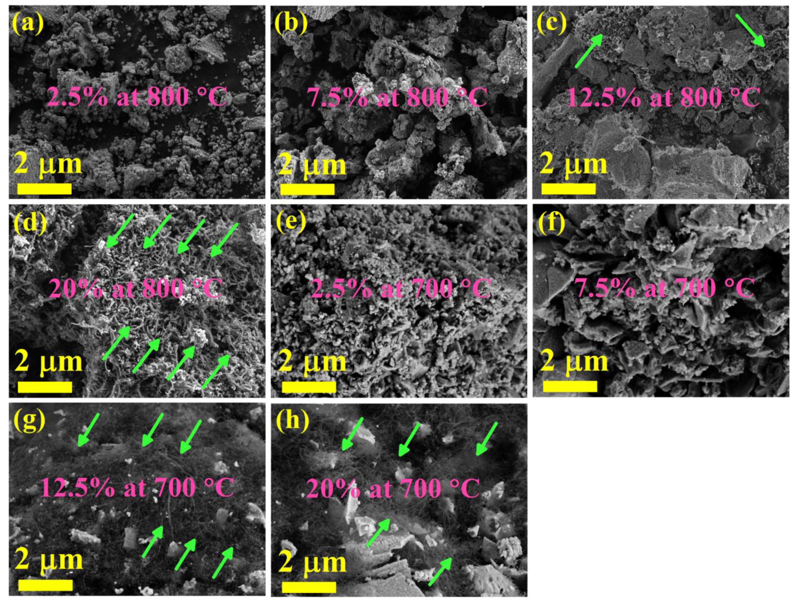
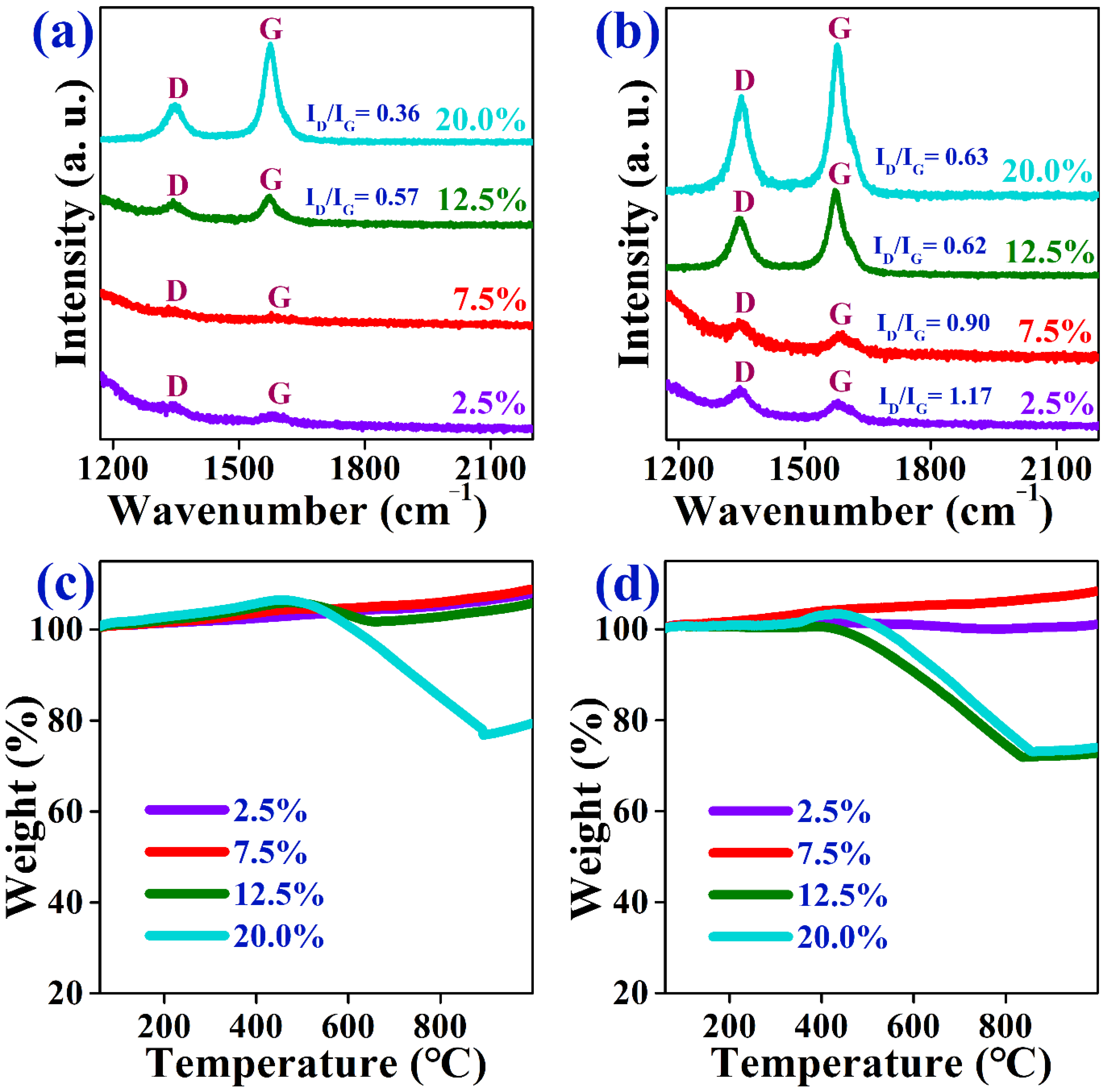
2.3. Characterization of Spent Catalysts

To identify the reasons responsible for maintaining the high activity for prolonged times of the as-prepared catalysts, the used catalysts have been analyzed by means of PXRD, SEM, Raman spectroscopy, and TGA after performing the DRM reaction for 50.0 h at reaction temperatures of 700 and 800 °C, separately. The PXRD analysis was done for the spent catalysts to investigate the Ni sintering property on the support. Figure 8a displays the PXRD patterns of the used catalysts after performing the DRM reaction for 50.0 h at 800 °C, which were very similar to those of the reduced catalysts (Figure 1b). Only the Ni/CeO2/20 catalyst exhibited a very small peak at 2θ of 26.27°, which is attributed to the deposition of carbon, indicating that increasing the Ni-loading over a specific limit induces the formation of coke. It is noteworthy that the Ni@CeO2/2.5 and Ni@CeO2/7.5 catalysts did not show any peaks for the Ni phase although performing the reaction at a high temperature (800 °C) for 50.0 h, signifying the excellent resistance for sintering, which is due to the robust interaction between the active phase (Ni0) and support (CeO2). This results in maintaining a high dispersion of Ni-NPs throughout the infrastructure of the support and prohibiting their agglomeration, hence preventing the coke deposition, which eventually leads to keeping a high catalytic activity towards the DRM reaction for prolonged periods. To calculate the size of Ni-NPs for the spent catalysts, the PXRD was performed at a slow scan rate (0.6°/min) in the 2θ range from 43.0 to 46.5 (Figure 8b). There was an increase in the Ni-NPs size of the Ni@CeO2/12.5 catalyst after performing the reaction for 50.0 h at 800 °C, where the size increased from 20.8 nm before the reaction to 27.8 nm after the reaction. In the case of the Ni/CeO2/20 catalyst, the expansion in the Ni-NPs size was from 24.6 to 27.0 nm, where the reaction over this catalyst survived only for 11.0 h.
Figure 8c shows that the PXRD patterns of the used catalysts after performing the DRM reaction for 50.0 h at 700 °C, which were also the same for the reduced catalysts (Figure 1b), except for the appearance of a very small peak at 2θ of 26.27° (indicated by ♣) for the Ni/CeO2/12.5 and Ni/CeO2/20 catalysts, which is attributed to the formation of carbon on the catalysts’ surfaces during the DRM reaction. There were no peaks that corresponded to the carbon in the PXRD patterns of the Ni/CeO2/2.5 and Ni/CeO2/7.5 catalysts after the DRM reaction occurred for 50.0 h at 700 °C, which are very harsh conditions for executing the DRM reaction where the coke readily forms at low reaction temperatures, indicating the super resistance of these two catalysts to carbon deposition. More importantly, there were not any noticeable peaks related to the Ni phase in these two catalysts, even after performing the PXRD analysis at a very low scan speed (Figure 8d), suggesting that Ni-NPs were still highly dispersed within the CeO2 support and no sintering occurred.
Figure 9a–d shows the FESEM images of the spent catalysts after performing the DRM reaction for 50.0 h at 800 °C. The Ni@CeO2/2.5 and Ni@CeO2/7.5 catalysts did not exhibit any carbon filaments on their surfaces (Figure 9a,b). Meanwhile, the Ni@CeO2/12.5 catalyst showed small content of coke on its surface (Figure 9c). In the case of the Ni@CeO2/20 catalyst, the coke formation was critical (Figure 9d), where the carbon filaments fully covered the catalyst surface. This critical coke deposition resulted in the blockage of the reactor after only 11.0 h, and hence the mandatory necessity to switch off the reactor. Although the Ni/CeO2/12.5/Impreg catalyst has the same content of Ni as the Ni@CeO2/12.5 catalyst, the former showed serious coke deposition on its surface compared to the latter (Figure S4a,b). This severe coke resulted in the deactivation of the catalyst after only 1.5 h, which emphasizes the importance of adjusting the Ni content and selecting the appropriate synthetic strategy in controlling the coke formation and hence dominating the catalytic performance towards the DRM reaction.
Figure 9e–h shows the FESEM images of the used catalysts after performing the DRM reaction at 700 °C. Although suppressing the deposition of carbon is intractable to be achieved at a temperature of 700 °C, due to the difficulty in achieving the balance between the CH4 decomposition and CO2 activation [59], the Ni@CeO2/2.5 and Ni@CeO2/7.5 catalysts did not show any observable carbon filaments on their surface after proceeding with the reaction for 50.0 h at 700 °C. This refers to the super resistance against coke formation even under harsh operating reaction conditions. With increasing the Ni-loading, carbon deposition started to happen where the Ni@CeO2/12.5 catalyst shows observable carbon filaments on its surface (Figure 9g) after performing the DRM reaction for 50.0 h. At a high loading of Ni (Ni@CeO2/20), the carbon deposition was more severe, where the carbon filaments covered most of the catalyst surface (Figure 9h), although occurring the reaction for only 2.0 h. This reveals the fundamental role of Ni-loading in controlling the carbon formation during the DRM process, which is one of the major reasons for deactivating the DRM catalysts. The catalyst synthesized by the impregnation method (Ni/CeO2/12.5/Impreg) showed very clear carbon filaments on its surface (Figure S4d) compared to that prepared by the one-pot strategy (Ni@CeO2/12.5) (Figure S4c) although the former served for the DRM reaction for only 20.0 min; meanwhile, the latter served for 50.0 h. It can be concluded that the method of introducing Ni to the support has a crucial role in controlling the catalytic activity of Ni-based catalysts towards the DRM reaction, where it highly dominates the carbon deposition.
The nature of the carbon formed on the catalyst surface during the DRM reaction is essential for interpreting the catalytic behavior of material towards the DRM. The intensity of the D band relative to that of the G band (ID/IG) is used to determine the graphitization degree [60] of carbon deposited on the catalysts’ surfaces after employing the DRM reaction for 50.0 h. When the reaction reached 50.0 h at 800 °C, there were almost no D and G bands for the Ni@CeO2/2.5 and Ni@CeO2/7.5 catalysts (Figure 10a), suggesting the absence of carbon in agreement with the PXRD and FESEM data. This again confirms that these two catalysts have excellent resistance to coke deposition. For the Ni@CeO2/12.5 catalyst, the intensities of the D and G bands were small, indicating the low content of carbon. When the Ni-loading was increased to 20 wt% (Ni@CeO2/20), the intensities of the D and G bands increased too much compared to the former catalysts. Furthermore, the ID/IG ratio was very low (0.36), proposing the high graphitization degree of carbon deposited on the catalysts’ surfaces during the DRM reaction. This explains why the Ni@CeO2/20 catalyst survived only for 11.0 h, where the highly graphitized carbon is hard to be removed from the catalyst’ surface, and hence led to blocking the Ni-active sites. As a result, the catalyst was fully deactivated after only 11.0 h. It can be concluded that adjusting the Ni-loading is very crucial for maximizing the coke resistance of Ni@CeO2-based catalysts and hence maximizing the durability for prolonged periods.
Figure S5a shows the Raman spectra for the Ni@CeO2/12.5 and Ni/CeO2/12.5/Impreg. It is obvious that the latter catalyst showed very high intensities of D and G bands compared to the former, indicating the high content of carbon deposited on the latter catalyst, although it survived only for 1.5 h. Even worse, the Ni/CeO2/12.5/Impreg exhibited a very low value of the ID/IG ratio (0.33), implying that the method of introducing Ni to the support has a significant role in suppressing the formation of the graphitized carbon on the catalysts’ surfaces during the DRM reaction (Table S4).
Figure 10b shows the Raman spectra of the spent catalysts after performing the DRM process for 50.0 h at 700 °C. The first peak (D) is attributed to the structural defects and lattice distortions in the sp3-hybridized carbon systems, and the second peak (G) is related to the in-plane vibrations of the sp2-bonded carbon atoms with a high degree of symmetry and graphitization [9]. It is clear that increasing the Ni-loading resulted in decreasing the ID/IG ratio, suggesting that the high loading of Ni enhances the graphitization degree of the deposited carbon. The high intensities of the D and G bands for the carbon formed on the Ni@CeO2/12.5 and Ni@CeO2/20 catalysts suggest a high content of carbon deposited on their surfaces. Moreover, the carbon showed ID/IG ratios of 0.62 and 0.63, indicating the high graphitization degree of carbon deposited on the catalysts’ surface during the DRM process, which is very harmful to the catalytic performance, where the highly graphitized carbon is difficult to remove from the surface of the catalyst. This drives the blocking of the Ni-active sites and eventually a deterioration in the catalysts’ activity. Figure S5b shows the Raman spectra for Ni@CeO2/12.5 and Ni/CeO2/12.5/Impreg catalysts, where the latter catalyst displayed a low ID/IG ratio (0.48) compared to the former (0.62), although the latter catalyst served only for 20.0 min when used for DRM at 700 °C.
The spent catalysts were analyzed by the TGA analysis to estimate the amounts of carbon species formed on their surfaces during the DRM reaction (Figure 10c,d). When the DRM reaction was operated at 800 °C for 50.0 h, the TGA profiles (Figure 10c) of the Ni@CeO2/2.5 and Ni@CeO2/7.5 catalysts did not show any weight loss related to carbon. Meanwhile, the Ni@CeO2/12.5 and Ni@CeO2/20 catalysts showed weight losses of 3.5 and 28.1%, respectively.
It is noteworthy to observe that the carbon formed on the Ni@CeO2/12.5 catalyst was fully removed at a temperature of about 650 °C. In addition, the carbon that formed on Ni@CeO2/20 catalyst was fully removed at about 897 °C. This indicates that increasing the Ni-loading over 12.5 wt% not only enhances the formation of coke but also improves the graphitization degree of the carbonaceous species formed on the catalysts’ surfaces during the DRM reaction which makes it more difficult to remove these species. This results in the easiness of blocking the Ni-active sites and hence deactivating the catalyst after short periods of operation. After performing the DRM process at 700 °C for 50.0, the Ni@CeO2/2.5 and Ni@CeO2/7.5 catalysts did not display any weight loss corresponding to the oxidation of carbon species (Figure 10d), indicating the absence of carbon on these two catalysts after serving for the DRM reaction for 50.0 h, in agreement with the PXRD and FESEM data.
On the other hand, the Ni@CeO2/12.5 and Ni@CeO2/20 catalysts showed weight losses of 28.13 and 26.94%, suggesting that the high loadings of Ni enhance the formation of coke during the DRM reaction. It should be noted that Ni@CeO2/12.5 and Ni@CeO2/20 catalysts showed similar coke formation, although the latter catalyst served only for 2.0 h, implying that the excessive loadings of Ni are very deleterious for the DRM catalysts, where it ameliorates the deposition of coke, and hence deactivating the catalyst after short periods of operation for the DRM reaction. The TGA profiles of the Ni@CeO2/12.5 catalyst after performing the reaction for 50.0 h at 700 and 800 °C showed that the weight losses were 28.13 and 3.5 wt%, respectively, indicating that the barrier of eliminating the carbon formed during the DRM reaction can be surmounted by increasing the reaction temperature. The results of analyzing the spent catalysts are consistent with the above discussion about the catalytic performance and deactivation process.
Based on the aforementioned results, the high catalytic activity and stability of the Ni@CeO2/7.5 catalyst can be ascribed to: (1) the homogenous distribution of the active phase (Ni0) within the substructure of the support (CeO2), (2) the excellent resistance for coke formation, (3) the confinement of the Ni-NPs by the support, (4) the small size of Ni-NPs and their strong interaction with the support, which inhibit the sintering of the NPs during the material synthesis and catalysis of the DRM reaction, and hence maintain stable catalytic performance for long-term periods, and (5) the advantageous characteristics of CeO2 where the oxygen vacancies on CeO2 participates in activating and dissociating CO2, and the mobile oxygen in CeO2 eliminates the carbon formed during the DRM reaction [34]. The above results reveal that the Ni@CeO2/7.5 catalyst, synthesized by a scalable one-pot strategy, has a superb resistance for sintering and coke formation even at low reaction temperatures, at which the coke is easily formed, therefore overcoming the essential challenges for the commercialization of DRM catalysts. Because of the excellent resistance for sintering and coke deposition, the herein synthesized catalyst may have promising applications in other reforming reactions, such as the steam reforming of methane, to maximize the production of H2.

3. Experimental Section

3.1. Materials

Cerium(III) nitrate hexahydrate (Ce(NO3)3·6H2O, ≥98%), nickel(II) nitrate hexahydrate (Ni(NO3)2·6H2O, ≥98%), and citric acid monohydrate (HOC(CO2H)(CH2CO2H)2·H2O, ≥99.5%) were purchased from Samchun Pure Chemicals, Pyeongtaek, Korea. Deionized water was obtained from UP 900 (Human, Seoul, Korea) and utilized as a solvent for preparing all solutions. All chemicals were used as received without any further purification.

3.2. Synthesis of Catalysts

The catalysts were synthesized by the one-pot method as follows: 7.53 g of Ce(NO3)3·6H2O were dissolved in 100 mL of distilled water, followed by the addition of the appropriate amount of Ni(NO3)2·6H2O, then stirred for 1.0 h. In another beaker, 6.74 g of HOC(CO2H)(CH2CO2H)2·H2O were dissolved in 100 mL of distilled water and then stirred for 1.0 h. The latter solution was added slowly to the former; then, the mixture was stirred for 2.0 h at room temperature. The mixture was heated at 80.0 °C in an oven until the mixture turned into a large-green crispy foam, then the temperature was increased to 100 °C and kept at this temperature for 6.0 h. The obtained foam was ground into a fine powder in a mortar using a pestle. The powder was then calcined in a furnace for two steps: 300 °C for 2.0 h to remove citric acid, then the temperature was increased to 400 °C and kept at this temperature for 4.0 h. The ramping rate was 1 °C/min for the two steps. Four catalysts were prepared by the above method to provide Ni-loadings of 2.5, 7.5, 12.5, and 20 wt% with respect to the CeO2, where the weight of the Ce precursor was the same for all catalysts. The catalysts were named as follows: Ni@CeO2/2.5, Ni@CeO2/7.5, Ni@CeO2/12.5, and Ni@CeO2/20 for the Ni-loadings of 2.5, 7.5, 12.5, and 20 wt%, respectively. A fifth sample was prepared by the wet impregnation method, where the support (CeO2) was synthesized as above except without the addition of Ni precursor. Thereafter, the Ni solution was impregnated to the support to provide Ni-loading for the Ni@CeO2/12.5 sample as well. The impregnated sample was named Ni/CeO2/12.5/Impreg.

3.3. Physical Characterization of Catalysts

Powder X-ray diffraction (PXRD) analysis was done using a Bruker D8 Advance diffractometer (Germany) operated at 40 kV and 40 mA. Cu Kα source (wavelength = 0.15406 nm) was used as a radiation source. The materials before and after the DRM reaction were analyzed in the 2θ range from 20 to 100° at a scan rate of 2°/min. For reduced and spent catalysts, additional measurements were performed at a slow scan rate of 0.6°/min in the 2θ range from 43.0 to 46.5° to observe the weak Ni peak. The crystallite size of Ni0 NPs was calculated using the Scherrer equation: [44]
Ni0 crystallite size = (Kλ)/(βcosθ)
where K is a shape factor, λ is the wavelength of the X-ray source, β is the full width at half-maximum in radians, and θ is the peak position in radians.
A Brunauer–Emmett–Teller (BET) analysis was done using BELSORP-mini-II (MicrotracBEL, Osaka, Japan). The samples were degassed under vacuum at 150 °C for 6.0 h, then subjected to nitrogen adsorption–desorption at –196 °C. The pore-size distribution was calculated by Barrett–Joymer–Halenda (BJH) method. Transmission Electron Microscopy (TEM) images were obtained with a Tecnai G2 F30 (FEI Company, Hillsboro, OR, USA) apparatus at 300 kV. The appropriate amount of the reduced catalysts was dispersed in about 5.0 mL of absolute ethanol and sonicated for around 10 min. A few drops of the obtained suspensions were put on a 300-mesh carbon film grid (CF300-CU, Electron Microscopy Sciences, Hatfield, UK), then dried at room temperature. Energy-dispersive X-ray spectroscopy (EDX) mapping images were obtained with the AZtecTEM device (Oxford, Abingdon, UK). The reduction properties of the as-prepared materials were analyzed by hydrogen-temperature programmed reduction (H2-TPR) using an Autochem2920 (Micromeritics, Norcross, GA, USA). An amount of 100 mg of the catalyst was pre-treated at 200 ℃ for 1.0 h under a He atmosphere, then cooled to room temperature.
The H2-TPR analysis was performed in the temperature range from 50 to 1000 °C under 10% H2/Ar atmosphere (50 mL/min) and ramping rate of 10 ℃/min. Inductively coupled plasma atomic emission spectroscopy (ICP-AES) analysis was performed using the Optima 7300 DV (Perkin-Elmer, Waltham, MA, USA) to define the chemical composition of the as-synthesized catalysts. A mixture of hydrochloric acid and nitric acid was utilized to dissolve the samples before the measurements. X-ray photoelectron microscopy (XPS) analysis was performed using a Thermo Scientific K-Alpha XPS system (Thermo Fisher Scientific, Waltham, MA, USA) equipped with a micro-focused monochromatic Al Kα X-ray source (1486.6 eV). A 400 μm X-ray beam was used at 6 mA × 12 kV. The spectra were acquired in the constant analyzer energy mode with a pass energy of 400 eV. Field-emission scanning electron microscopy (FESEM) of the spent catalysts was performed by CLALA (Tescan, Kohoutovice, Czech). Raman spectra of the spent catalysts were recorded at room temperature using a LabRAM HR800 UV-Visible-NIR system (Horiba, Kyoto, Japan) equipped with a charge-coupled detector (CCD) and an InGaAs array detector with an excitation laser wavelength of 514 nm and 1800 Grating, an ND 10% filter, an acquisition time of 8 s, and a wavenumber range of 1000~2500 cm–1. Thermogravimetric (TGA) analysis was done using Setaram Labsys TGA Evo (KEP, Mougins, France). An amount of 15 mg of the spent catalyst was heated to 1000 °C at a heating rate of 10 °C/min, where the weight change was measured under 40 mL/min of air.

3.4. Catalytic Activity Measurements

Catalytic reactions were performed in a fixed-bed reactor using a quartz tube of 4 mm internal diameter, where 15 mg of quartz wool was put inside the tube before adding the catalyst layer (catalyst weight = 75.0 mg). Prior to the reaction, the calcined powder was in situ was reduced to 800 °C for 1.50 h at a ramping rate of 5 °C/min and a flow rate of 100 sccm (H2/N2 = 1/4) to obtain the active phase (Ni0). The feeding gas was then changed to the CH4, CO2, and N2 at a molar ratio of 1:1:1 and P = 1.0 atm, where the flow rate was the same as 10.0 mL/min for each gas (i.e., the total flow rate was 30.0 mL/min). The reaction was performed at T= 700 °C and 800 °C, separately, for 50.0 h. The temperature outside the reactor was kept at 160 °C. The total weight hourly space velocity (WHSV) was 24,000 mL gcat–1 h–1. The WHSV for only reactants (CH4 and CO2) was 16,000 mL gcat–1 h–1 if we exclude the flow rate of diluting gas (N2). The reaction temperature was controlled with a thermocouple located axially at the center of the catalyst bed. The effluent was quantified by online gas chromatography (HP 6890 GC) equipped with Carboxen 1000 packed column (Supelco 12390-U) and a thermal conductivity detector. The CH4 and CO2 conversions, as well as the H2/CO ratio, were calculated using the following equations:
CH 4   conversion   ( % ) = [ CH 4 ] in     [ CH 4 ] out   [ CH 4 ] in × 100
CO 2   conversion   ( % ) = [ CO 2 ] in     [ CO 2 ] out   [ CO 2 ] in × 100
where [CH4]in and [CH4]out are the inlet and outlet volume flow of CH4 gas, respectively. Meanwhile, [CO2]in and [CO2]out are the inlet and outlet volume flow of CO2 gas, respectively
H 2 CO = [ H 2 ] out [ CO ] out [ H 2 ] out [ CO ] out
where [H2]out and [CO]out are the outlet volume of H2 and CO gases, respectively.

4. Conclusions

In this study, Ni-NP-supported CeO2 catalysts were prepared by two different synthetic strategies and various loadings of Ni. At the same loading of Ni, the catalyst prepared by the one-pot method presented an excellent catalytic performance at reaction temperatures of 800 and 700 °C, respectively, compared to that obtained by the traditional impregnation method. The catalysts prepared at Ni-loadings of 7.5 and 12.5 wt% showed a high performance towards the DRM reaction. Interestingly, the Ni@CeO2/7.5 catalyst displayed zero coke formation after serving for the DRM process for 50.0 h, even at 700 °C. The high catalytic activity and durability are mainly due to the superb coke resistance, redox properties of CeO2, and premium dispersion of the active phase with robust interaction with the support. This work provides an economical and scalable strategy for incorporating Ni into CeO2 to produce an excellent catalyst for the DRM reaction. The herein synthesized catalyst showed outstanding resistance for both metal sintering and coke formation, which are the two main challenges for developing the DRM catalyst, and hence, this may provide a useful route for commercializing the DRM process.

Supplementary Materials

The following are available online at https://www.mdpi.com/article/10.3390/catal12040423/s1, Figure S1. PXRD patterns of calcined (a) and reduced (b), Ni@CeO2/12.5 (One-pot) and Ni/CeO2/12.5/Impreg (Impregnated) catalysts. (c) PXRD patterns of the reduced Ni@CeO2/12.5 (One-pot) and Ni/CeO2/12.5/Impreg (Impregnated) catalysts at a slow scanning speed of 0.6 °/min (2θ = 43.0 – 46.5°); Figure S2. XPS spectra of Ni 2p in the reduced Ni@CeO2/12.5 (One-pot) and Ni/CeO2/12.5/Impreg (Impregnated) catalysts; Figure S3. CH4 conversions (a), CO2 conversions (b), and H2/CO ratios of Ni@CeO2/12.5 (One-pot) and Ni/CeO2/12.5/Impreg (Impregnated) catalysts at a reaction temperature of 800 °C and WHSV of 24,000 mL gcat–1 h–1 for 50.0 h; Figure S4. FESEM images of Ni@CeO2/12.5 (One-pot) and Ni/CeO2/12.5/Impreg (Impregnated) catalysts after operating the DRM reaction for 50.0 h, at temperature of 800 °C (a and b) and 700 °C (c and d). The green arrows refer to the carbon filaments deposed on the catalysts’ surface after the reaction; Figure S5. Raman spectra of Ni@CeO2/12.5 (One-pot) and Ni/CeO2/12.5/Impreg (Impregnated) catalysts after operating the DRM reaction for 50.0 h, at temperature of 800 °C (a) and 700 °C (b); Table S1: BET surface area, total pore volume, and average pore diameter of the calcined and reduced samples; Table S2. Crystal sizes of CeO2 after calcination and reduction evaluated by Scherrer’s equation based on XRD patterns; Table S3. Comparison of the DRM catalytic activity of our catalyst with recent Ni/CeO2-based catalysts reported in literature; Table S4. Comparison of the DRM catalytic activity of our catalyst with recent Ni/CeO2-based catalysts reported in literature. References: [61,62,63,64,65,66,67,68,69,70,71,72,73,74,75].

Author Contributions

Conceptualization, A.A.-S.E.; methodology, S.B.K., A.A.-S.E. and K.L.; validation, S.B.K. and M.-J.K.; formal analysis, S.B.K. and M.-J.K.; investigation, S.B.K.; resources, S.B.K. and K.L.; data curation, S.B.K., A.A.-S.E., M.-J.K., E.S.G., and J.-R.Y.; writing—original draft preparation, S.B.K., A.A.-S.E., and M.-J.K.; writing—review and editing, A.A.-S.E. and K.L.; visualization, S.B.K., A.A.-S.E., and M.-J.K.; supervision, A.A.-S.E. and K.L.; project administration, K.L.; funding acquisition, K.L. All authors have read and agreed to the published version of the manuscript.

Funding

This research was supported by the Korea Electric Power Corporation (Grant number: R20XO02-16). This research was also supported by a Korea Institute of Energy Technology Evaluation and Planning (KETEP) grant funded by the Korean government (MOTIE) (20214000000090, Fostering Human Resources Training in Advanced Hydrogen Energy Industry).

Data Availability Statement

The data presented in this study are available on request from the corresponding author.

Conflicts of Interest

There are no conflicts to declare.

References

  1. Jung, S.; Lee, J.; Moon, D.H.; Kim, K.-H.; Kwon, E.E. Upgrading biogas into syngas through dry reforming. Renew. Sustain. Energy Rev. 2021, 143, 110949. [Google Scholar] [CrossRef]
  2. Subramanian, S.; Song, Y.; Kim, D.; Yavuz, C.T. Redox and Nonredox CO2 Utilization: Dry Reforming of Methane and Catalytic Cyclic Carbonate Formation. ACS Energy Lett. 2020, 5, 1689–1700. [Google Scholar] [CrossRef]
  3. Li, M.; Sun, Z.; Hu, Y.H. Catalysts for CO2 reforming of CH4: A review. J. Mater. Chem. A 2021, 9, 12495–12520. [Google Scholar] [CrossRef]
  4. Li, M.; Sun, Z.; Hu, Y.H. Thermo-photo coupled catalytic CO2 reforming of methane: A review. Chem. Eng. J. 2022, 428, 131222. [Google Scholar] [CrossRef]
  5. Sheng, K.; Luan, D.; Jiang, H.; Zeng, F.; Wei, B.; Pang, F.; Ge, J. NixCoy Nanocatalyst Supported by ZrO2 Hollow Sphere for Dry Reforming of Methane: Synergetic Catalysis by Ni and Co in Alloy. ACS Appl. Mater. Interfaces 2019, 11, 24078–24087. [Google Scholar] [CrossRef]
  6. Liu, H.; Li, Y.; He, D. Recent Progress of Catalyst Design for Carbon Dioxide Reforming of Methane to Syngas. Energy Technol. 2020, 8, 1900493. [Google Scholar] [CrossRef]
  7. Yentekakis, I.V.; Panagiotopoulou, P.; Artemakis, G. A review of recent efforts to promote dry reforming of methane (DRM) to syngas production via bimetallic catalyst formulations. Appl. Catal. B Environ. 2021, 296, 120210. [Google Scholar] [CrossRef]
  8. Mohammadi, M.M.; Shah, C.; Dhandapani, S.K.; Chen, J.; Abraham, S.R.; Sullivan, W.; Buchner, R.D.; Kyriakidou, E.A.; Lin, H.; Lund, C.R.F.; et al. Single-Step Flame Aerosol Synthesis of Active and Stable Nanocatalysts for the Dry Reforming of Methane. ACS Appl. Mater. Interfaces 2021, 13, 17618–17628. [Google Scholar] [CrossRef]
  9. Kim, H.; Eissa, A.A.-S.; Kim, S.B.; Lee, H.; Kim, W.; Seo, D.J.; Lee, K.; Yoon, W.L. One-pot synthesis of a highly mesoporous Ni/MgAl2O4 spinel catalyst for efficient steam methane reforming: Influence of inert annealing. Catal. Sci. Technol. 2021, 11, 4447–4458. [Google Scholar] [CrossRef]
  10. Al-Swai, B.M.; Osman, N.; Alnarabiji, M.S.; Adesina, A.A.; Abdullah, B. Syngas Production via Methane Dry Reforming over Ceria–Magnesia Mixed Oxide-Supported Nickel Catalysts. Ind. Eng. Chem. Res. 2019, 58, 539–552. [Google Scholar] [CrossRef]
  11. Wu, J.; Qiao, L.-Y.; Zhou, Z.-F.; Cui, G.-J.; Zong, S.-S.; Xu, D.-J.; Ye, R.-P.; Chen, R.-P.; Si, R.; Yao, Y.-G. Revealing the Synergistic Effects of Rh and Substituted La2B2O7 (B = Zr or Ti) for Preserving the Reactivity of Catalyst in Dry Reforming of Methane. ACS Catal. 2019, 9, 932–945. [Google Scholar] [CrossRef]
  12. Lovell, E.C.; Großman, H.; Horlyck, J.; Scott, J.; Mädler, L.; Amal, R. Asymmetrical Double Flame Spray Pyrolysis-Designed SiO2/Ce0.7Zr0.3O2 for the Dry Reforming of Methane. ACS Appl. Mater. Interfaces 2019, 11, 25766–25777. [Google Scholar] [CrossRef]
  13. Teh, L.P.; Setiabudi, H.D.; Timmiati, S.N.; Aziz, M.A.A.; Annuar, N.H.R.; Ruslan, N.N. Recent progress in ceria-based catalysts for the dry reforming of methane: A review. Chem. Eng. Sci. 2021, 242, 116606. [Google Scholar] [CrossRef]
  14. Minette, F.; de Wilde, J. Multi-scale modeling and simulation of low-pressure methane bi-reforming using structured catalytic reactors. Chem. Eng. J. 2021, 407, 127218. [Google Scholar] [CrossRef]
  15. Liang, T.-Y.; Raja, D.S.; Chin, K.C.; Huang, C.-L.; Sethupathi, S.A.P.; Leong, L.K.; Tsai, D.-H.; Lu, S.-Y. Bimetallic Metal–Organic Framework-Derived Hybrid Nanostructures as High-Performance Catalysts for Methane Dry Reforming. ACS Appl. Mater. Interfaces 2020, 12, 15183–15193. [Google Scholar] [CrossRef]
  16. Li, Z.; Lin, Q.; Li, M.; Cao, J.; Liu, F.; Pan, H.; Wang, Z.; Kawi, S. Recent advances in process and catalyst for CO2 reforming of methane. Renew. Sustain. Energy Rev. 2020, 134, 110312. [Google Scholar] [CrossRef]
  17. Lyu, Y.; Jocz, J.; Xu, R.; Stavitski, E.; Sievers, C. Nickel Speciation and Methane Dry Reforming Performance of Ni/CexZr1–xO2 Prepared by Different Synthesis Methods. ACS Catal. 2020, 10, 11235–11252. [Google Scholar] [CrossRef]
  18. Zhang, F.; Liu, Z.; Chen, X.; Rui, N.; Betancourt, L.E.; Lin, L.; Xu, W.; Sun, C.-J.; Abeykoon, A.M.M.; Rodriguez, J.A.; et al. Effects of Zr Doping into Ceria for the Dry Reforming of Methane over Ni/CeZrO2 Catalysts: In Situ Studies with XRD, XAFS, and AP-XPS. ACS Catal. 2020, 10, 3274–3284. [Google Scholar] [CrossRef]
  19. Das, S.; Sengupta, M.; Bag, A.; Shah, M.; Bordoloi, A. Facile synthesis of highly disperse Ni–Co nanoparticles over mesoporous silica for enhanced methane dry reforming. Nanoscale 2018, 10, 6409–6425. [Google Scholar] [CrossRef]
  20. de la Cruz-Flores, V.G.; Martinez-Hernandez, A.; Gracia-Pinilla, M.A. Deactivation of Ni-SiO2 catalysts that are synthetized via a modified direct synthesis method during the dry reforming of methane. Appl. Catal. A Gen. 2020, 594, 117455. [Google Scholar] [CrossRef]
  21. Shi, L.-Y.; Li, Y.-X.; Xue, D.-M.; Tan, P.; Jiang, Y.; Liu, X.-Q.; Sun, L.-B. Fabrication of highly dispersed nickel in nanoconfined spaces of as-made SBA-15 for dry reforming of methane with carbon dioxide. Chem. Eng. J. 2020, 390, 124491. [Google Scholar] [CrossRef]
  22. Niu, J.; Liland, S.E.; Yang, J.; Rout, K.R.; Ran, J.; Chen, D. Effect of oxide additives on the hydrotalcite derived Ni catalysts for CO2 reforming of methane. Chem. Eng. J. 2019, 377, 119763. [Google Scholar] [CrossRef]
  23. Yang, E.; Nam, E.; Lee, J.; Lee, H.; Park, E.D.; Lim, H.; An, K. Al2O3-Coated Ni/CeO2 nanoparticles as coke-resistant catalyst for dry reforming of methane. Catal. Sci. Technol. 2020, 10, 8283–8294. [Google Scholar] [CrossRef]
  24. Rezaei, R.; Moradi, G.; Sharifnia, S. Dry Reforming of Methane over Ni-Cu/Al2O3 Catalyst Coatings in a Microchannel Reactor: Modeling and Optimization Using Design of Experiments. Energy Fuels 2019, 33, 6689–6706. [Google Scholar] [CrossRef]
  25. Guo, Y.; Li, Y.; Ning, Y.; Liu, Q.; Tian, L.; Zhang, R.; Fu, Q.; Wang, Z.-J. CO2 Reforming of Methane over a Highly Dispersed Ni/Mg–Al–O Catalyst Prepared by a Facile and Green Method. Ind. Eng. Chem. Res. 2020, 59, 15506–15514. [Google Scholar] [CrossRef]
  26. Zhang, M.; Zhang, J.; Wu, Y.; Pan, J.; Zhang, Q.; Tan, Y.; Han, Y. Insight into the effects of the oxygen species over Ni/ZrO2 catalyst surface on methane reforming with carbon dioxide. Appl. Catal. B Environ. 2019, 244, 427–437. [Google Scholar] [CrossRef]
  27. Seo, J.-C.; Kim, H.; Lee, Y.-L.; Nam, S.; Roh, H.-S.; Lee, K.; Park, S.B. One-Pot Synthesis of Full-Featured Mesoporous Ni/Al2O3 Catalysts via a Spray Pyrolysis-Assisted Evaporation-Induced Self-Assembly Method for Dry Reforming of Methane. ACS Sustain. Chem. Eng. 2021, 9, 894–904. [Google Scholar] [CrossRef]
  28. Sokefun, Y.O.; Joseph, B.; Kuhn, J.N. Impact of Ni and Mg Loadings on Dry Reforming Performance of Pt/Ceria-Zirconia Catalysts. Ind. Eng. Chem. Res. 2019, 58, 9322–9330. [Google Scholar] [CrossRef]
  29. Shi, C.; Wang, S.; Ge, X.; Deng, S.; Chen, B.; Shen, J. A review of different catalytic systems for dry reforming of methane: Conventional catalysis-alone and plasma-catalytic system. J. CO2 Util. 2021, 46, 101462. [Google Scholar] [CrossRef]
  30. Bian, Z.; Das, S.; Wai, M.H.; Hongmanorom, P.; Kawi, S. A Review on Bimetallic Nickel-Based Catalysts for CO2 Reforming of Methane. Chemphyschem 2017, 18, 3117–3134. [Google Scholar] [CrossRef] [Green Version]
  31. Lian, Z.; Olanrele, S.O.; Si, C.; Yang, M.; Li, B. Critical Role of Interfacial Sites between Nickel and CeO2 Support in Dry Reforming of Methane: Revisit of Reaction Mechanism and Origin of Stability. J. Phys. Chem. C 2020, 124, 5118–5124. [Google Scholar] [CrossRef]
  32. Yan, X.; Hu, T.; Liu, P.; Li, S.; Zhao, B.; Zhang, Q.; Jiao, W.; Chen, S.; Wang, P.; Lu, J.; et al. Highly efficient and stable Ni/CeO2-SiO2 catalyst for dry reforming of methane: Effect of interfacial structure of Ni/CeO2 on SiO2. Appl. Catal. B: Environ. 2019, 246, 221–231. [Google Scholar] [CrossRef]
  33. Omoregbe, O.; Danh, H.T.; Abidin, S.Z.; Setiabudi, H.D.; Abdullah, B.; Vu, K.B.; Vo, D.-V.N. Influence of Lanthanide Promoters on Ni/SBA-15 Catalysts for Syngas Production by Methane Dry Reforming. Procedia Eng. 2016, 148, 1388–1395. [Google Scholar] [CrossRef] [Green Version]
  34. Wang, F.; Han, K.; Yu, W.; Zhao, L.; Wang, Y.; Wang, X.; Yu, H.; Shi, W. Low Temperature CO2 Reforming with Methane Reaction over CeO2-Modified Ni@SiO2 Catalysts. ACS Appl. Mater. Interfaces 2020, 12, 35022–35034. [Google Scholar] [CrossRef]
  35. Wang, J.B.; Tai, Y.-L.; Dow, W.-P.; Huang, T.-J. Study of ceria-supported nickel catalyst and effect of yttria doping on carbon dioxide reforming of methane. Appl. Catal. A Gen. 2001, 218, 69–79. [Google Scholar] [CrossRef]
  36. Liu, Z.; Grinter, D.C.; Lustemberg, P.G.; Nguyen-Phan, T.-D.; Zhou, Y.; Luo, S.; Waluyo, I.; Crumlin, E.J.; Stacchiola, D.J.; Zhou, J.; et al. Dry Reforming of Methane on a Highly-Active Ni-CeO2 Catalyst: Effects of Metal-Support Interactions on C−H Bond Breaking. Angew. Chem. Int. 2016, 55, 7455–7459. [Google Scholar] [CrossRef] [Green Version]
  37. Safavinia, B.; Wang, Y.; Jiang, C.; Roman, C.; Darapaneni, P.; Larriviere, J.; Cullen, D.A.; Dooley, K.M.; Dorman, J.A. Enhancing CexZr1–xO2 Activity for Methane Dry Reforming Using Subsurface Ni Dopants. ACS Catal. 2020, 10, 4070–4079. [Google Scholar] [CrossRef]
  38. Liu, Y.; Wu, Y.; Akhtamberdinova, Z.; Chen, X.; Jiang, G.; Liu, D. Dry Reforming of Shale Gas and Carbon Dioxide with Ni-Ce-Al2O3 Catalyst: Syngas Production Enhanced over Ni-CeOx Formation. ChemCatChem 2018, 10, 4689–4698. [Google Scholar] [CrossRef]
  39. Chein, R.-Y.; Fung, W.-Y. Syngas production via dry reforming of methane over CeO2 modified Ni/Al2O3 catalysts. Int. J. Hydrog. Energy 2019, 44, 14303–14315. [Google Scholar] [CrossRef]
  40. Yao, L.; Galvez, M.E.; Hu, C.; da Costa, P. Synthesis Gas Production via Dry Reforming of Methane over Manganese Promoted Nickel/Cerium–Zirconium Oxide Catalyst. Ind. Eng. Chem. Res. 2018, 57, 16645–16656. [Google Scholar] [CrossRef]
  41. Wolfbeisser, A.; Sophiphun, O.; Bernardi, J.; Wittayakun, J.; Föttinger, K.; Rupprechter, G. Methane dry reforming over ceria-zirconia supported Ni catalysts. Catal. Today 2016, 277, 234–245. [Google Scholar] [CrossRef] [Green Version]
  42. Lu, Y.; Wang, R.; Zhao, Y.; Wang, S.; Ma, X. Effect of Ce doping on the catalytic performance of xNiCeOy@SiO2 catalysts for dry reforming of methane. Asia-Pac. J. Chem. Eng. 2021, 16, e2678. [Google Scholar] [CrossRef]
  43. Rodriguez-Gomez, A.; Lopez-Martin, A.; Ramirez, A.; Gascon, J.; Caballero, A. Elucidating the Promotional Effect of Cerium in the Dry Reforming of Methane. ChemCatChem 2021, 13, 553–563. [Google Scholar] [CrossRef]
  44. Eissa, A.A.; Kim, N.H.; Lee, J.H. Rational design of a highly mesoporous Fe–N–C/Fe3C/C–S–C nanohybrid with dense active sites for superb electrocatalysis of oxygen reduction. J. Mater. Chem. A 2020, 8, 23436–23454. [Google Scholar] [CrossRef]
  45. Cychosz, K.A.; Guillet-Nicolas, R.; García-Martínez, J.; Thommes, M. Recent advances in the textural characterization of hierarchically structured nanoporous materials. Chem. Soc. Rev. 2017, 46, 389–414. [Google Scholar] [CrossRef]
  46. Venkataswamy, P.; Rao, K.N.; Jampaiah, D.; Reddy, B.M. Nanostructured manganese doped ceria solid solutions for CO oxidation at lower temperatures. Appl. Catal. B: Environ. 2015, 162, 122–132. [Google Scholar] [CrossRef]
  47. Sagar, V.T.; Pintar, A. Enhanced surface properties of CeO2 by MnOx doping and their role in mechanism of methane dry reforming deduced by means of in-situ DRIFTS. Appl. Catal. A Gen. 2020, 599, 117603. [Google Scholar] [CrossRef]
  48. Tao, K.; Zhang, Y.; Terao, S.; Tsubaki, N. Development of platinum-based bimodal pore catalyst for CO2 reforming of CH4. Catal. Today 2010, 153, 150–155. [Google Scholar] [CrossRef]
  49. Deng, G.; Zhang, G.; Zhu, X.; Guo, Q.; Liao, X.; Chen, X.; Li, K. Optimized Ni-based catalysts for methane reforming with O2-containing CO2. Appl. Catal. B: Environ. 2021, 289, 120033. [Google Scholar] [CrossRef]
  50. Palma, V.; Ruocco, C.; Meloni, E.; Ricca, A. Influence of Catalytic Formulation and Operative Conditions on Coke Deposition over CeO2-SiO2 Based Catalysts for Ethanol Reforming. Energies 2017, 10, 1030. [Google Scholar] [CrossRef] [Green Version]
  51. Sutradhar, N.; Sinhamahapatra, A.; Pahari, S.; Jayachandran, M.; Subramanian, B.; Bajaj, H.C.; Panda, A.B. Facile Low-Temperature Synthesis of Ceria and Samarium-Doped Ceria Nanoparticles and Catalytic Allylic Oxidation of Cyclohexene. J. Phys. Chem. C 2011, 115, 7628–7637. [Google Scholar] [CrossRef]
  52. Li, H.; Lu, G.; Dai, Q.; Wang, Y.; Guo, Y.; Guo, Y. Hierarchical Organization and Catalytic Activity of High-Surface-Area Mesoporous Ceria Microspheres Prepared Via Hydrothermal Routes. ACS Appl. Mater. Interfaces 2010, 2, 838–846. [Google Scholar] [CrossRef]
  53. Palma, V.; Ruocco, C.; Meloni, E.; Ricca, A. Renewable Hydrogen from Ethanol Reforming over CeO2-SiO2 Based Catalysts. Catalysts 2017, 7, 226. [Google Scholar] [CrossRef]
  54. Li, M.; van Veen, A.C. Tuning the catalytic performance of Ni-catalysed dry reforming of methane and carbon deposition via Ni-CeO2-x interaction. Appl. Catal. B Environ. 2018, 237, 641–648. [Google Scholar] [CrossRef] [Green Version]
  55. Chen, X.; Li, M.; Guan, J.; Wang, X.; Williams, C.T.; Liang, C. Nickel–Silicon Intermetallics with Enhanced Selectivity in Hydrogenation Reactions of Cinnamaldehyde and Phenylacetylene. Ind. Eng. Chem. Res. 2012, 51, 3604–3611. [Google Scholar] [CrossRef]
  56. Kim, M.-J.; Youn, J.-R.; Kim, H.J.; Seo, M.W.; Lee, D.; Go, K.S.; Lee, K.B.; Jeon, S.G. Effect of surface properties controlled by Ce addition on CO2 methanation over Ni/Ce/Al2O3 catalyst. Int. J. Hydrog. Energy 2020, 45, 24595–24603. [Google Scholar] [CrossRef]
  57. Jang, W.-J.; Kim, H.-M.; Shim, J.-O.; Yoo, S.-Y.; Jeon, K.-W.; Na, H.-S.; Lee, Y.-L.; Jeong, D.-W.; Bae, J.W.; Nah, I.W.; et al. Key properties of Ni–MgO–CeO2, Ni–MgO–ZrO2, and Ni–MgO–Ce(1−x)Zr(x)O2 catalysts for the reforming of methane with carbon dioxide. Green Chem. 2018, 20, 1621–1633. [Google Scholar] [CrossRef]
  58. Jang, W.-J.; Shim, J.-O.; Kim, H.-M.; Yoo, S.-Y.; Roh, H.-S. A review on dry reforming of methane in aspect of catalytic properties. Catal. Today 2019, 324, 15–26. [Google Scholar] [CrossRef]
  59. Zhang, M.; Zhang, J.; Zhou, Z.; Chen, S.; Zhang, T.; Song, F.; Zhang, Q.; Tsubaki, N.; Tan, Y.; Han, Y. Effects of the surface adsorbed oxygen species tuned by rare-earth metal doping on dry reforming of methane over Ni/ZrO2 catalyst. Appl. Catal. B Environ. 2020, 264, 118522. [Google Scholar] [CrossRef]
  60. Eissa, A.A.; Peera, S.G.; Kim, N.H.; Lee, J.H. g-C3N4 templated synthesis of the Fe3C@NSC electrocatalyst enriched with Fe–Nx active sites for efficient oxygen reduction reaction. J. Mater. Chem. A 2019, 7, 16920–16936. [Google Scholar] [CrossRef]
  61. Rood, S.C.; Ahmet, H.B.; Gomez-Ramon, A.; Torrente-Murciano, L.; Reina, T.R.; Eslava, S. Enhanced ceria nanoflakes using graphene oxide as a sacrificial template for CO oxidation and dry reforming of methane. Appl. Catal. B: Environ. 2019, 242, 358–368. [Google Scholar] [CrossRef]
  62. Marinho, A.L.A.; Rabelo-Neto, R.C.; Epron, F.; Bion, N.; Toniolo, F.S.; Noronha, F.B. Embedded Ni nanoparticles in CeZrO2 as stable catalyst for dry reforming of methane. Appl. Catal. B: Environ. 2020, 268, 118387. [Google Scholar] [CrossRef]
  63. Pappacena, A.; Razzaq, R.; De Leitenburg, C.; Boaro, M.; Trovarelli, A. The Role of Neodymium in the Optimization of a Ni/CeO2 and Ni/CeZrO2 Methane Dry Reforming Catalyst. Inorganics 2018, 6, 39. [Google Scholar] [CrossRef] [Green Version]
  64. Liu, Z.; Zhang, F.; Rui, N.; Li, X.; Lin, L.; Betancourt, L.E.; Su, D.; Xu, W.; Cen, J.; Attenkofer, K.; et al. Highly Active Ceria-Supported Ru Catalyst for the Dry Reforming of Methane: In Situ Identification of Ruδ+–Ce3+ Interactions for Enhanced Conversion. ACS Catal. 2019, 9, 3349–3359. [Google Scholar] [CrossRef]
  65. Horváth, A.; Németh, M.; Beck, A.; Maróti, B.; Sáfrán, G.; Pantaleo, G.; Liotta, L.F.; Venezia, A.M.; La Parola, V. Strong impact of indium promoter on Ni/Al2O3 and Ni/CeO2-Al2O3 catalysts used in dry reforming of methane. Appl. Catal. A Gen. 2021, 621, 118174. [Google Scholar] [CrossRef]
  66. Li, B.; Yuan, X.; Li, B.; Wang, X. Ceria-modified nickel supported on porous silica as highly active and stable catalyst for dry reforming of methane. Fuel 2021, 301, 121027. [Google Scholar] [CrossRef]
  67. da Fonseca, R.O.; Rabelo-Neto, R.C.; Simões, R.C.C.; Mattos, L.V.; Noronha, F.B. Pt supported on doped CeO2/Al2O3 as catalyst for dry reforming of methane. Int. J. Hydrogen Energy 2020, 45, 5182–5191. [Google Scholar] [CrossRef]
  68. Tu, P.H.; Le, D.N.; Dao, T.D.; Tran, Q.-T.; Doan, T.C.D.; Shiratori, Y.; Dang, C.M. Paper-structured catalyst containing CeO2–Ni flowers for dry reforming of methane. Int. J. Hydrogen Energy 2020, 45, 18363–18375. [Google Scholar] [CrossRef]
  69. Marinho, A.L.A.; Toniolo, F.S.; Noronha, F.B.; Epron, F.; Duprez, D.; Bion, N. Highly active and stable Ni dispersed on mesoporous CeO2-Al2O3 catalysts for production of syngas by dry reforming of methane. Appl. Catal. B Environ. 2021, 281, 119459. [Google Scholar] [CrossRef]
  70. Muñoz, M.A.; Calvino, J.J.; Rodríguez-Izquierdo, J.M.; Blanco, G.; Arias, D.C.; Pérez-Omil, J.A.; Hernández-Garrido, J.C.; González-Leal, J.M.; Cauqui, M.A.; Yeste, M.P. Highly stable ceria-zirconia-yttria supported Ni catalysts for syngas production by CO2 reforming of methane. Appl. Surf. Sci. 2017, 426, 864–873. [Google Scholar] [CrossRef]
  71. Padi, S.P.; Shelly, L.; Komarala, E.P.; Schweke, D.; Hayun, S.; Rosen, B.A. Coke-free methane dry reforming over nano-sized NiO-CeO2 solid solution after exsolution. Catal. Commun. 2020, 138, 105951. [Google Scholar] [CrossRef]
  72. Araiza, D.G.; Arcos, D.G.; Gómez-Cortés, A.; Díaz, G. Dry reforming of methane over Pt-Ni/CeO2 catalysts: Effect of the metal composition on the stability. Catal. Today 2021, 360, 46–54. [Google Scholar] [CrossRef]
  73. Sadeq Al-Fatesh, A.; Olajide Kasim, S.; Aidid Ibrahim, A.; Hamza Fakeeha, A.; Elhag Abasaeed, A.; Alrasheed, R.; Ashamari, R.; Bagabas, A. Combined Magnesia, Ceria and Nickel catalyst supported over γ-Alumina Doped with Titania for Dry Reforming of Methane. Catalysts 2019, 9, 188. [Google Scholar] [CrossRef] [Green Version]
  74. Damaskinos, C.M.; Zavašnik, J.; Djinović, P.; Efstathiou, A.M. Dry reforming of methane over Ni/Ce0.8Ti0.2O2-δ: The effect of Ni particle size on the carbon pathways studied by transient and isotopic techniques. Appl. Catal. B Environ. 2021, 296, 120321. [Google Scholar] [CrossRef]
  75. Luisetto, I.; Tuti, S.; Romano, C.; Boaro, M.; Di Bartolomeo, E.; Kesavan, J.K.; Kumar, S.S.; Selvakumar, K. Dry reforming of methane over Ni supported on doped CeO2: New insight on the role of dopants for CO2 activation. J. CO2 Util. 2019, 30, 63–78. [Google Scholar] [CrossRef]
Figure 1. PXRD patterns of calcined (a) and reduced (b) Ni@CeO2 catalysts prepared at different Ni-loadings (2.5, 7.5, 12.5, and 20 wt%). (c) PXRD patterns of the reduced Ni@CeO2 catalysts at a slow scanning speed of 0.6°/min (2θ = 43.0–46.5°).
Catalysts 12 00423 g001
Figure 2. N2 adsorption/desorption isotherms and BJH pore-size distributions of calcined (a,b) and reduced (c,d) Ni@CeO2 catalysts prepared at different Ni-loadings (2.5, 7.5, 12.5, and 20 wt%).
Catalysts 12 00423 g002
Figure 3. TEM (a,b), HAADF-STEM (c), and corresponding energy-dispersive X-ray elemental mapping images (df) of the reduced Ni@CeO2/7.5 catalyst. The green dotted circles in (b) highlight some of the Ni-NPs on CeO2 support.
Catalysts 12 00423 g003
Figure 4. TEM (a,b), HAADF-STEM (c), and corresponding energy-dispersive X-ray elemental mapping images (df) of the reduced Ni@CeO2/12.5 catalyst. The green dotted circles in (a,b) highlight some of the Ni-NPs on CeO2 support.
Catalysts 12 00423 g004
Figure 5. (a) H2–TPR profiles of pure CeO2 and Ni@CeO2 catalysts prepared at different Ni-loadings (2.5, 7.5, 12.5, and 20 wt%). (b) XPS spectra of Ni 2p in reduced Ni@CeO2 catalysts prepared at different Ni-loadings (2.5, 7.5, 12.5, and 20 wt%).
Catalysts 12 00423 g005
Figure 6. XPS spectra of Ce 3d in reduced Ni@CeO2 catalysts prepared at different Ni-loadings (2.5, 7.5, 12.5, and 20 wt%) (a) and the concentration of Ce3+ in reduced Ni@CeO2 catalysts estimated by XPS analysis (b).
Catalysts 12 00423 g006
Figure 7. CH4 conversions (a), CO2 conversions (b), and H2/CO ratios (c) of the Ni@CeO2 catalysts prepared at different Ni-loadings (2.5, 7.5, 12.5, and 20 wt%) at a reaction temperature of 800 °C and WHSV of 24,000 mL gcat–1 h–1 for 50.0 h. CH4 conversions (d), CO2 conversions (e), and H2/CO ratios (f) of the Ni@CeO2 catalysts at a reaction temperature of 700 °C and WHSV of 24,000 mL gcat–1 h–1 for 50.0 h.
Catalysts 12 00423 g007
Figure 8. PXRD patterns of the Ni@CeO2 catalysts prepared at different Ni-loadings (2.5, 7.5, 12.5, and 20 wt%) after operating the DRM reaction for 50.0 h at temperatures of 800 °C (a) and 700 °C (c). (c) PXRD patterns at a slow scanning speed of 0.6°/min of the Ni@CeO2 catalysts (2θ = 43.0–46.5°), after operating the DRM reaction for 50.0 h at temperatures of 800 °C (b) and 700 °C (d).
Catalysts 12 00423 g008
Figure 9. FESEM images of the Ni@CeO2 catalysts prepared at different Ni-loadings (2.5, 7.5, 12.5, and 20 wt%) after operating the DRM reaction for 50.0 h at temperatures of 800 °C (ad) and 700 °C (eh). The green arrows refer to the carbon filaments deposited on the catalysts’ surfaces after the reaction.
Catalysts 12 00423 g009
Figure 10. Raman spectra and TGA data of the used catalysts. (a,b) Raman spectra of the Ni@CeO2 catalysts prepared at different Ni-loadings (2.5, 7.5, 12.5, and 20 wt%) after operating the DRM reaction for 50.0 h, at temperatures of 800 °C (a) and 700 °C (b). (c,d) TGA profiles of Ni@CeO2 catalysts after operating the DRM reaction for 50.0 h at a temperature of 800 °C (c) and 700 °C (d).
Catalysts 12 00423 g010
Publisher’s Note: MDPI stays neutral with regard to jurisdictional claims in published maps and institutional affiliations.

