Article

Photoelectrochemical Degradation of Organic Pollutants on a La3+ Doped BiFeO3 Perovskite

by
Oluchi V. Nkwachukwu
1,
Charles Muzenda
1,
Babatope O. Ojo
1,
Busisiwe N. Zwane
1,2,
Babatunde A. Koiki
1,
Benjamin O. Orimolade
1,
Duduzile Nkosi
1,
Nonhlangabezo Mabuba
1,3 and
Omotayo A. Arotiba
1,3,*
1
Department of Chemical Sciences, University of Johannesburg, Johannesburg 2028, South Africa
2
DST/Mintek Nanotechnology Innovation Centre, University of Johannesburg, Johannesburg 2028, South Africa
3
Centre for Nanomaterials Science Research, University of Johannesburg, Johannesburg 2028, South Africa
*
Author to whom correspondence should be addressed.
Catalysts 2021, 11(9), 1069; https://doi.org/10.3390/catal11091069
Submission received: 29 July 2021 / Revised: 24 August 2021 / Accepted: 25 August 2021 / Published: 2 September 2021

Abstract

:
Towards nonconventional wastewater treatment methods for the degradation of organic pollutants in wastewater, a perovskite-based photoelectrochemical system was developed. Bismuth ferrite doped with lanthanum (La-BiFeO3, La-BFO) perovskite was synthesised through a hydrothermal method with low calcination temperature for the photoelectrochemical degradation of orange II dye and other cocktails of dyes. Photoanodes were prepared by the deposition of the perovskites on a fluorine-doped tin oxide (FTO) substrate. The photoanodes were characterised using XRD, FESEM, FTIR and UV-vis diffuse reflectance. The photoelectrochemical properties of the synthesised photoanodes were investigated with chronoamperometry and electrochemical impedance spectroscopy (including Mott–Schottky analysis). The results show that all La3+-doped BFO photoanodes exhibited a higher absorption edge in the visible light region than the undoped BFO. The photocurrent response of 10% La-BFO (the best performing electrode) exhibited a three times higher current response than the pure BFO. In addition, the electrode exhibited a good degradation efficiency of 84.2% within 120 min with applied bias potential of 2 V at a pH of 7. EIS studies showed a significant enhancement of the interfacial electron transfer of the charge carriers. The enhancements in electrode performances were attributed to the synergistic effect of the applied bias potential and the introduction of La3+ into the BFO matrix. This study therefore shows that the photoelectrocatalytic performance of BFO for water treatment can be improved by the introduction of perovskites-doping ions such as La3+.

Graphical Abstract

1. Introduction

Water pollution is a global issue, partly because of the discharge of effluents into the environment from industries such as pharmaceutical, textiles and metallurgical. Over the years, several methods have been employed in the treatment of water. However, most of these conventional methods are associated with drawbacks, such as the generation of secondary pollution, incomplete mineralisation and, in some cases, cost intensiveness. Photoelectrochemical oxidation is one of the more advanced oxidation processes, which uses both light and applied potential to facilitate the production of strong oxidants that non-selectively oxidise organics in wastewater [1]. The photoelectrochemical (PEC) degradation of organic pollutants using different semiconducting materials has attracted considerable interest over the past few years owing to its advantages over photocatalysis. Photocatalysis (PC), which has been widely utilised in non-conventional water treatment, is found to be associated with drawbacks such as difficulty in catalyst recovery and electron–hole recombination [2]. However, in PEC, as photons illuminate the catalyst, electrons are migrated to the cathode via the applied bias potential for efficient separation of photogenerated charges to combat electron–hole recombination.
Semiconductors, such as ZnO, TiO2, and WO3, have been utilised as photocatalyts in PEC degradation. However, their photocatalytic efficiencies are limited by their large band gaps, which inhibit their absorption of visible light [3,4]. Therefore, research has been geared towards other catalysts that are visible light-active with minimal electron–hole recombinations and narrow band gaps. In addition, improved techniques, such as metal doping [5,6], metal decoration [7], and heterojunction structure formation [8,9], have been explored in the preparation of the semiconductors to harness their efficiency in water treatment. Perovskites, which are binary metal oxides with a formula ABO3, have been sought-after materials owing to their interesting properties, such as thermal stability, low band gap, visible light activity, ionic conductivity and excellent electron mobility [10,11]. Bismuth ferrite (BiFeO3, BFO) is an established multiferroic material that exhibits both ferroelectric and antiferromagnetic properties at room temperature. BFO has found wide applicability in memory devices, data storage, sensors, water splitting and photocatalysis, owing to its narrow band gap (2.2–2.8 eV), chemical stability and low cost [12,13,14]. With regards to its application in water treatment, Gao et al. [15] synthesised BFO for the degradation of methyl red via the sol-gel method involving different calcination temperatures. They recorded well-dispersed BFO nanoparticles with tunable sizes and bandgaps. Additionally, Wang et al. [16] studied the effects of BFO for the degradation of dye and phenols. Recently, studies have shown that the photocatalytic performance of pure BFO is not impressive due to the recombination of photogenerated electron–hole pairs, high current leakage and impurity phases formed during preparation [12]. The poor photocatalytic performance of pure BFO has led to the preparation of heterojunction structures of BFO in photocatalysis, such as BFO/BVO [8], N-rGO/BiFeO3 [17], BiFeO3/CuO [18], BiFeO3/Pt [19], BiFeO3/Sm/Pd [12], BiFeO3/La3+ [20] BiFeO3/Zr [5] and BiFeO3-gC3N4-WO3 [9] for enhancements in the degradation of organics in water. Many studies have also shown that the partial substitution of A site Bi3+ in BFO with rare earth metals, such as La3+, Nd3+, Eu3+ and Gd3+, can lead to enhanced ferroelectric and magnetisation properties, which leads to a magnetoelectric (ME) effect via the sinking of impurity phases and the disparity in ionic radii, since lanthanides have smaller ionic radii compared to Bi3+ [21,22,23].
Meng et al. [24] synthesised La-doped BFO for the photocatalysis degradation of organic pollutants in water. They reported that La-doped BFO photocatalysts manifested greater photocatalytic enhancement, which they attributed to reductions in electron–hole recombination, narrow band gap, low charge transfer resistance, and the smaller radius of La3+ (RLa3+ = 0.116 nm) than Bi3+ (RBi3+ = 0.117 nm). Singh and co-workers [20] also reported the substitution of La3+ in BFO for the photocatalysis degradation of methylene blue. They recorded enhancements in photocatalytic degradation efficiency, increased surface area, and improved ferromagnetic behaviour. However, the authors did not report on the performance of the bare BFO photocatalyst. Dhanalakshmi [25] demonstrated the enhanced photocatalytic degradation of phenol red using La3+-doped BiFeO3.
Reports on the photoelectrocatalytic degradation of recalcitrant organics using perovskites are sparse, and to the best of our knowledge, the photoelectrocatalytic application of La-doped BFO has not been reported. We thus report the effects of Bi1-xLaxFeO3 (mole fraction x = 0.00, 0.05, 0.10, 0.15) prepared through the hydrothermal method with a low calcination temperature. The perovskite was prepared through the hydrothermal method with a low calcination temperature. The powdered perovskite was deposited onto an FTO substrate using the drop-cast technique. The photoanodes were characterised with XRD, FESEM/ EDS and UV diffusive reflectance spectroscopy (UV-DRS). Chronoamperometry for photocurrent response and electrochemical impedance spectroscopy (EIS) were employed to study the electrochemical properties of BFO and La-BFO photoanodes. Additionally, the influence of lanthanum on bismuth ferrite was also studied using Mott–Schottky plots to understand the charge separation efficiency and suppression of recombination of charged carriers, and a mechanism for improved charge separation was proposed. For the photoelectrocatalytic degradation experiments, Orange II, Congo red and methylene blue were selected as model organic dyes, and acetaminophen and sulfamethoxazole were selected as model pharmaceutical pollutants (See chemical structures of all the selected organic pollutants in Supplementary Figure S1).

2. Results and Discussion

2.1. Structural and Morphology Characterisation of the Electrodes

We utilised the powdered XRD technique to analyse the crystal structure of FTO, BFO, 5% La-BFO, 10% La-BFO and 15% La-BFO. All the major reflection peaks in the XRD pattern are indexed to perovskite BFO with space group R3c confirmed by JCPDS card no. 01-084-7216 with a rhombohedral structure [26]. The peaks around 28° and 30.3° in Figure 1a correspond to the presence of secondary phase Bi25FeO40 [24]. This could be due to the kinetics of formation and the metastable nature of BiFeO3. These impurities disappeared as the lanthanum doping increased, confirming the stability of lanthanum and its ability to suppress impurities [20,24]. The enlarged view of diffraction peaks (104) and (110) shows a split as the lanthanum doping increases, and these splits broadened slightly to a higher angle, implying that substituting La3+ into Bi3+ brings about distortions in the lattice structure (Figure 1a insert). These results suggest the effect of doping lanthanum into the bismuth ferrite lattice, and they agree with the findings of the Singh and Weng groups [20,24]. The field emission scanning electron microscope (FESEM) image of BFO shows an irregular mixture of rods and globules, with some falling into the nanoscale. The effect of La3+ doping could not be observed from the FESEM; however, the EDS image confirms the presence of lanthanum in the 10% La-BFO composite (Figure 1c). The FTIR spectra of Bi1-xLaxFeO3 (x = 0.00, 0.05, 0.10, 0.15) are shown in Figure 1d. The pronounced absorptive peaks around 400–600 cm−1 are the characteristics of metal oxide formation in all as-prepared samples. The peaks at 434 and 547 cm−1 could be the vibration along the Fe-O axis and O-Fe-O bending, which are both attributes of the FeO6 group in perovskites [21,27]. The peak at 632 cm−1 disappeared as lanthanum was incorporated into the matrix. The peaks around 695 cm−1 and 857 cm−1 could be a result of the vibration of Bi-O bonds [28]. These peaks confirm the formation of the perovskite structure in all the prepared samples.

2.2. UV-VIS Diffuse Reflectance Spectroscopic Characterisation of the Photoanodes

The optical properties of the as-prepared BFO, 5% La-BFO, 10% La-BFO and 15% La-BFO photoanodes were studied using UV–visible diffuse reflectance spectroscopy, and the results are shown in Figure 2a. All the materials show absorbance in the visible range. The effect of La doping can be seen by the increase in the absorbance in the visible range of 550 to 800 nm, with the 10% La doping giving the highest absorbance. The Tauc plot equation was then used to extract information with regards to the band gap energy of the semiconductors. The band gap energy was calculated using the Kubelka–Munk (K–M) Equation (1)
αhυ = A(hυ − Eg)n/2
where α, h, υ, Eg, and A are the absorption coefficient, Planck constant, light frequency, band gap energy, and absorption constant, respectively. The parameter “n” in the equation depends on the characteristics of the transition in any semiconductor, i.e., direct transition (n = 1) or indirect transition (n = 2). Bismuth ferrite has a direct band gap, hence n = 1 [29]. The plot of (αhυ)2 against hυ in Figure 2b shows that the band gaps of pure BFO, 5%, 10% and 15% La-BFO were 2.4, 2.37, 2.28 and 2.33 eV, respectively. This band gap engineering may be attributed to the formation of an impurity level or the formation of localised electronic states due to the incorporation of La3+, which brought about a shift in the Fermi level. The 10% La-BFO photoanode absorbed more visible light than other photoanodes owing to the reduced band gap of 2.28 eV in comparison to the other materials. This will likely favour the photoelectrocatalytic degradation of the water pollutants [20,30,31]. Additionally, these band gaps are within the range of the previously reported studies of BFO [18,32].

2.3. Electrochemical and Photoelectrochemical Characterisation

The photocurrent response of BFO and 10% La-BFO deposited on the FTO substrate was investigated using chronoamperometry in 0.1 M Na2SO4 solution with a bias potential of 0.6 V. Figure 3a shows the photocurrent response with respect to time under the ON/OFF chopped light illumination mode for BFO and 10% La-BFO. The photocurrents generated show that the electrode is responsive to photoelectrochemical stimulus, hence its suitability as a visible light-responsive photoanode [33]. Moreover, the 10% La-BFO displayed a greater photoelectrochemical response, which is three times higher (0.1180 mAcm−2) than the pure BFO (0.0372 mAcm−2). This is an indication that 10% La-BFO will promote greater current mobility and reduction when in recombination with photogenerated electron–hole pairs. This equally shows the positive effect of the La3+ ion in the BFO perovskite matrix for photocatalytic applications. To further understand the charge transfer properties of BFO and 10% La-BFO samples, EIS experiments were performed. The semi-circular arc in the Nyquist plot in Figure 3b denotes the charge transfer resistance (Rct) at the interface of the electrodes. The BFO has an Rct of 4500 Ω, while the incorporation of La3+ ion into BFO markedly reduced the Rct to 406 Ω, suggesting a greater interfacial charge transfer efficiency, the low recombination of photogenerated electron–hole pairs, and the greater mobility and diffusion of electrons [2]. The bode plot (Figure 3b inset) was used to calculate the lifetime (τ) of the electrons generated in the photoanodes of the BFO and 10% La-BFO composites from Equation (2). The lifetime is inversely proportional to the peak frequency, as seen in Equation (2) [34].
τ = 1 / ω max = 1 / 2 π f max
where fmax is the maximum frequency. The calculated electron lifetimes (τ) for BFO and 10% La-BFO are 21.67 ms and 117.66 ms, respectively. These results show that an appropriate doping amount of lanthanum in the bismuth ferrite lattice increased the electron lifetime in the photoanode. Mott–Schottky analysis was carried out to estimate the donor concentrations in the BFO and 10% La-BFO films [35]. The flat band potential VFB of BFO and 10% La-BFO was estimated by the Mott–Schottky (MS) measurement using Equation (3).
1 / C 2 = 2 / ( e Ɛ Ɛ 0 N D )   .   ( E a p p E F B k T / e )
where C is the semiconductor capacitance, e is elementary charge, Ɛ is the dielectric constant of the semiconductor (assumed to be 52) [36], Ɛo is the permittivity of the vacuum 8.85 × 10⁻¹² Fm−1, ND is the donor density, Eapp is the applied potential, K is the Boltzmann constant 1.38 × 10⁻²³ Fm−1, EFB is the flat band potential, and T is the absolute temperature [2]. From the slope of the plot of 1/C2 against E (potential), the ND is estimated, while the EFB is estimated from the intercept on the x-axis [34]. Figure 3c shows the MS plot for BFO and 10% La-BFO. The negative slope depicts that both samples are p-type semiconductors. The VFB estimated from Equation (3) for BFO is −0.042 V (vs. Ag/AgCl), and −0.172 V (vs. Ag/AgCl) for 10% La-BFO. This reduction in VFB value shows a downward shift in the Fermi level of the 10% La-BFO electrode, which leads to the inhibition of the recombination of photogenerated electron–hole pairs [8,37]. The presence of La in the matrix causes excitation at lower energy and a favourable pathway for the charge transfer from the CB of BFO to the CB of La, thus increasing the charge carrier concentration by hindering the recombination. These electrons, which are trapped within the lanthanum, enable holes to fully participate in the oxidation reaction. As estimated from the slope, the carrier density (ND) values for BFO and 10% La-BFO are 6.564 × 1022 cm−3 and 1.861 × 1023 cm−3, respectively. We also observed an enhancement in the carrier density of the doped electrode.

2.4. Photoelectrocatalytic Degradation of Pollutants

The photoelectrocatalytic performances of the samples BFO, 5% La-BFO, 10% La-BFO and 15% La-BFO photoanodes were evaluated using Orange II dye as a typical organic pollutant. The degradation process was performed under simulated solar light as described in Section 3.3 As seen in Figure 4a, the degradation percentages of Orange II dye at BFO and 10% La-BFO photoanodes were 55.3% and 84.2%, respectively, while those of the 5% La-BFO and 15% La-BFO photoanodes were 52.6% and 57.8%, respectively, as shown in the insert. These results show that the 10% La-BFO is the best performing photoanode for the degradation process. This improved performance can be ascribed to the narrow band gap and excellent charge separation, which reduced the recombination of electron–hole pairs. The results of the kinetic studies fit a pseudo-first order kinetic model, and Figure 4b shows lnC0/Ct plotted against reaction time. The apparent rate constants for BFO and 10% La-BFO were 6.73 × 10⁻³ min−1 and 15.4 × 10⁻³ min−1, respectively. The rate constant of 10% La-BFO shows that the abatement of Orange II was fastest with the 10% La-BFO electrode. To further show the performance of the photoelectrocatalytic process using the optimum photoanode (10% La-BFO), the degradation efficiencies obtained through photocatalytic (PC) and electrocatalytic oxidation (EC) were studied and presented in Figure 4c,d. From Figure 4c, we recorded degradation percentages of 5.7%, 60.6% and 84.2% for PC, EC and PEC, respectively. The corresponding rate constants were 0.00094 min−1, 0.0075 min−1 and 0.0154 min−1 for PC, EC and PEC. The application of bias potential increases the charge carrier separation, and consequently improves the catalytic degradation in the presence of light (photoelectrochemical oxidation or photoelectrocatalysis) at the 10% La-BFO photoanode. This shows the advantage of PEC over PC and EC. For a better understanding of the performance of PEC in the application of bias potential and light, the degree of electrochemical enhancement (E) and the degree of process synergy (S) were calculated using Equations (4) and (5), respectively [38].
E = (KPEC − KPC)/KPEC
S = (KPEC − (KPC + KEC))/KPEC
where KPEC, KPC and KEC are the apparent rate constants for the photoelectrocatalytic, photocatalytic and electrochemical degradation of Orange II dye, respectively. From Equation (4), we see that the degree of electrochemical enhancement was 0.938 (93.8%). This result suggests that the application of bias potential contributed immensely to the process. The degree of process synergy as calculated from Equation (5) was 0.451, which is greater than zero. This means that the performance of PEC degradation alone is more than the summation of the rate constants of PC and EC [39,40].
The pH value of the solution is one of the most important aspects that affects the decolourisation of azo dyes in the oxidation process. The PEC degradation of Orange II dye at pH 4, 7 and 10 resulted in degradation percentages of 56.7, 84.2 and 43.3%, respectively (Supplementary Figure S2). This result suggests that acidic medium and neutral pH favour the decolourisation of Orange II dye. This may be attributed to the protonated hydroxyl group developed on the surface, which causes more electrostatic interaction between Orange II (anionic dye) and the semiconductor [41]. Zhang [42] reported a rapid decolourisation of acid Orange II at acidic and neutral pH using the adsorption process.
The reusability and stability study of the 10% La-BFO photoanode was evaluated by replicating Orange II degradation under visible light for up to five cycles. After each cycle, the electrode was rinsed with deionised water. As shown in Supplementary Figure S3, the degradation rates are 84.2%, 84%, 82.8%, 82.2%, and 80%. These close values indicate a good measure of stability, and suggest the reusability of the photoanode without significant losses in catalytic performance.

2.5. Photoelectrocatalytic Degradation of Cocktail Pollutants and Pharmaceuticals

The 10% La-BFO was further used to simultaneously degrade 5 ppm each of Orange II, Congo red and methylene blue. This route serves as a guide to elucidate the performance of the photoanode in the degradation of myriad pollutants. There was considerable degradation of the pollutants as a result of the peak intensity reduction, as illustrated by the UV–vis spectrophotometer shown in Supplementary Figure S4. The degradation percentage of the dye mixture was calculated to be 44.8, 43.9 and 56% for Orange II, Congo red and methylene blue, respectively. The individual degradations of Congo red and methylene blue were calculated to be 76% and 93.7%, respectively. As expected, the rate of degradation in the cocktail was lower as compared to the individual dyes, owing to the presence of (i) higher concentrations of organic molecules, (ii) the increased complexity of the molecules that must be oxidised, and (iii) the matrix effect created by the presence of other organics in the solution. Furthermore, we applied the photoanode in the degradation of sulfamethoxazole and acetaminophen (data not shown) with degradation values of 36.8% and 54%, respectively. These results showed the capability of the photoanode in a competitive environment of numerous recalcitrant pollutants.

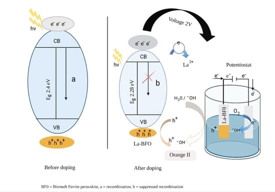
2.6. Trapping Experiment and Proposed Photoelectrocatalytic Activity Mechanism

A scavenger experiment was carried out to show the role of active species in the PEC degradation of Orange II and other pollutants used in this study. From the result shown in Figure S5, 0.5 mM of ethylenediaminetetraacetate (EDTA) salt and 0.2 mM of t-butanol (t-BuOH) was used to suppress the effects of hole and hydroxyl radical, respectively. The degradation percentage was reduced to 20% and 10% upon the addition of EDTA and t-BuOH, respectively. This shows that hydroxyl radical (·OH) and hole (h+) played synergistic roles in degrading the pollutants in this study. Table S1 shows the percentage degradation of Orange II dye in pH, stability and scavenger studies. Furthermore, to understand the separation of the photogenerated electron–holes in the composite over the pristine BFO, it is imperative to determine the band gap edge energy of the valence band and conduction band. The potentials at the point zero charge of the conduction band (CB) and valence band (VB) are estimated using Mulliken electronegativity in Equations (6) and (7) [43].
ECB = X − Ee − 0.5Eg
EVB = Eg + ECB
where ECB and EVB are the band potentials, X is the electronegativity of the semiconductor, and x is the electronegativity of the elements using the formula [X = [x(A)a x(B)b x(C)c]1/a+b+c; therefore, X is the electronegativity of BFO, calculated to be 5.89. Ee is the energy of the free electron on the hydrogen scale (4.5 eV), and Eg is the band gap of the semiconductor obtained from Equation (1). Via the above equation, EVB and ECB for BFO were calculated to be 2.59 eV and 0.19 eV, respectively. As illustrated in the scheme in Figure 5, when solar light irradiates on the La-BFO electrode, it produces electrons e and holes h+ (Equation (8)). Since the conduction band edge of BFO (0.19 eV) vs. NHE is more positive than the standard redox potential E0 (O2/O2) (−0.33 eV vs. NHE), the electrons at the CB of BFO cannot reduce O2 to O2·−. Thus, the superoxide radical is not the active species. Furthermore, the edge of the CB potential of BFO is more negative than the standard redox potential E0 (O2/H2O2) (0.685 eV vs. NHE), implying that oxygen adsorbed on the surface of the 10% La-BFO composite could react with electrons to form H2O2, which will further react with electron to form hydroxyl radicals (·OH) (Equations (9) and (10)). Hydroxyl radical has strong oxidising potential, enabling it to participate in photocatalytic reactions. The VB edge potential of BFO (2.59 eV vs. NHE) is more positive than the standard redox potential E0 (OH/OH) (1.99 eV vs. NHE), suggesting that the accumulated holes on the VB of the composite can oxidise OHads to form ·OH [44,45]. Via this mechanism, the hole can directly attack the dye to mineralise it, or can adsorb water to form a hydroxyl radical (Equations (11) and (12)). The doping of metals expands the wavelength of a semiconductor to absorb more visible light by creating localised electronic states, which results in a shift of the band gap and also alters the band edge by shifting the Fermi level in the doped system [24,46]. The doping of a rare earth element (La) into bismuth ferrite (BFO) in a similar way showed higher absorbance in the visible region, giving rise to a smaller band gap. According to the Mott–Schottky plot, BFO exhibited a p-type semiconductor, which means that the localised energy level is above the VB edge. The possible mechanisms that led to the suppression of photogenerated electron–hole pairs could have involved the lanthanum acting as an electron-trapping agent and an impurity sinking site for the photogenerated electron–hole pairs, which suppressed the recombination of the photogenerated electron–hole pairs. Alternatively, with the application of bias potential, the electrons could have been dragged to the counter electrode and reacted with the adsorbed oxygen to form hydroxyl radicals. This makes PEC an excellent method for the degradation of emerging pollutants, and is also one of its advantages over photocatalysis. These possible mechanisms will enable the holes to participate in directly attacking the pollutants or be adsorbed with H2O to form hydroxyl radicals (·OH), which, according to the scavengers study, are the dominant oxidising species. The mechanism of reaction is summarised in Equations (8)–(13):
La-BFO + hv → La-BFO (h+VB + eCB)
O2 + 2e + 2H+ → H2O2
H2O2 + e → ·OH + ·OH
h+ + Orange II → CO2 + H2O
h+ + H2O → ·OH + H+
·OH + Orange II → CO2 + H2O

3. Materials and Method

All the chemicals used were of analytical grade. Lanthanum nitrate hexahydrate (La(NO3)3.6H2O), bismuth nitrate pentahydrate (Bi(NO3)3.5H2O), iron nitrate nonahydrate (Fe(NO3)3.9H2O) and potassium hydroxide (KOH) were obtained from Sigma Aldrich. Deionised water was employed throughout this project.

3.1. Preparation of Bi1−xLaxFeO3 Perovskite

In a typical experiment, Bi1-xLaxFeO3 (mole fraction x = 0.00, 0.05, 0.10, 0.15) was synthesised by the hydrothermal/calcination method with modification [47]. Quantities of 0.1 M of bismuth, lanthanum and iron were weighed and dissolved in DI in a beaker with continuous stirring for 60 min. A 40 mL volume of 8 M KOH (mineraliser) was added into the mixture, and the pH was adjusted to 8 using 5 M nitric acid. The mixture was covered and stirred at room temperature for 72 h. Thereafter, the formed mixture was transferred into a sealed a stainless-steel autoclave (Teflon-lined) and was heated at 200 °C for 24 h, after which it was allowed to cool to room temperature. The brownish product was collected by centrifugation, washed with deionised water and absolute ethanol several times, and then dried in the oven following 1 h of calcination at 500 °C.

3.2. Structural, Morphology and Optical Characterisation of the Prepared Electrodes

The PANalytical X’Pert PRO X-ray diffractometer (XRD, Rigagu Ultima IV, Tokyo, Japan) was used to study the degree of crystallinity and the structure. The diffraction patterns were collected from the 2θ degree angle of 10–80° at the step size of 0.0170° using Cu radiation with a wavelength 0.154 nm. The generator was operated at a voltage of 40 kV and a current of 40 mA. The FTIR (Alpha Bruker, Germany) measurement ranged from 400 to 4000 cm−1. Electron micrographs were collected with field emission scanning electron microscopy (JEOL JSM-7500F, JEOL Ltd., Tokyo, Japan). UV-vis diffuse reflectance spectroscopy (DRS) measurements were taken with a Cary 60 UV-vis spectrophotometer (Agilent Technologies, Selangor, Malaysia).

3.3. Preparation of Bi1−xLaxFeO3 Photoanodes for Electrochemical and Photoelectrochemical Experiments

In preparing the photoanodes, 30 mg of the prepared samples were each dissolved in isopropanol and nafion solution in a ratio of 3:1; thereafter, the paste was drop-cast on FTO glass (50 mm × 13 mm × 2.2 mm, surface resistivity of ∼7 Ω/sq). The electrodes were dried in the oven for 2 h at 70 °C and were used as working electrodes. The electrochemical analyses were performed using Autolab PGSTAT204 (Metrohm, Utrecht, The Netherlands) potentiostat/galvanostat with a three-electrode system. The prepared FTO-BFO, FTO-5 wt. % La-BFO, FTO-10 wt. %-BFO and FTO-15 wt. % BFO photoanodes served as the working electrodes, while platinum foil and Ag/AgCl (3.0 M NaCl) were employed as counter and reference electrodes, respectively. A 100 W xenon lamp (solar simulator) was employed as the light source for the photoelectrocatalytic degradation. The photoanodes were facing the incident light at a distance of 10 cm. Chronoamperometry (photocurrent response) was carried out in 0.1 M Na2SO4 solution. Impedance spectroscopy was carried out in a 5 mM solution of K3[Fe(CN)6]3−/4− (prepared in 0.1 M KCl solution). Potential scans were performed to obtain data for Mott–Schottky plots without the application of light at room temperature in a pH 7 solution. For the PEC degradation experiments, 5 mg L−1 of Orange II was prepared in a 0.1 M solution of Na2SO4 as a supporting electrolyte in a 100 mL quartz glass for 120 min. Electrochemical degradation experiments were carried out in the absence of light with the application of only bias potential, while photocatalysis was carried out in the presence of light and working electrodes only. Aliquots were taken at different time interval to evaluate the concentration decay and degradation pattern of the Orange II using a UV–vis spectrophotometer. The effect of pH on the PEC removal efficiency was studied. In addition, the optimum photoanode 10% La-BFO was used to degrade methylene blue, Congo red, sulfamethoxazole and acetaminophen.

4. Conclusions

We successfully synthesised multiferroic Bi1-xLaxFeO3 (x = 0.05, 0.10, and 0.15) via the hydrothermal method with a low calcination temperature. The formation of La-doped BFO perovskite was confirmed by the XRD, SEM/EDS and FTIR results. The doping of this composite improved the photocurrent response to about three times higher than the pure BFO. The doping of BFO with La3+ caused a reduction in band gap and an extension of wavelength into the visible light region. When the 10% La-BFO electrode was applied for the photoelectrocatalytic degradation of Orange II dye, a degradation efficiency of 84.2% (higher than that of BFO alone) was recorded within 120 min. This photoanode also showed a decent degradation ability in the presence of a cocktail of PEC dyes and pharmaceutical pollutants, suggesting its robustness.

Supplementary Materials

The following are available online at https://www.mdpi.com/article/10.3390/catal11091069/s1, Figure S1: Chemical structure of Orange II, methylene blue and Congo red, Figure S2: pH study of degradation of Orange II using 10% La-BFO photoanode (5 ppm, 2 V), Figure S3: Stability study of PEC degradation of orange II, Figure S4. Simultaneous degradation of Orange II, Congo red and methylene blue using, 10% La-BFO photoanode (5 ppm, 2 V, pH 7), Figure S5: (a) Photoelectrocatalytic degradation of sulfamethoxazole and acetaminophen using 10% La-BFO; (b) Kinetic plots for degradation of sulfamethoxazole and acetaminophen (5 ppm; 2 V; pH 7), Figure S6: Trapping experiment for photoelectrocatalytic degradation of orange II using 10% La-BFO photoanode (5 ppm, 2 V, pH 7), Table S1: Percentage degradation of orange II dye: pH, stability and scavenger studies.

Author Contributions

Conceptualisation, O.V.N. and O.A.A.; funding acquisition, O.A.A.; investigation, O.V.N.; methodology, O.V.N., C.M. and O.A.A.; project administration, D.N.; resources, O.A.A.; supervision, O.A.A.; writing—original draft, O.V.N.; writing—review and editing, O.V.N., C.M., B.O.O. (Babatope O. Ojo), B.N.Z., B.A.K., B.O.O. (Benjamin O. Orimolade), D.N., N.M. and O.A.A. All authors have read and agreed to the published version of the manuscript.

Funding

This research was funded by the National Research Foundation of South Africa (CPRR Grant number 118546) and the Centre for Nanomaterials Science Research, University of Johannesburg. The APC was also funded funded by the National Research Foundation of South Africa.

Data Availability Statement

The data presented in this study are available on request from the corresponding author.

Acknowledgments

The authors wish to acknowledge the National Research Foundation of South Africa (CPRR Grant number 118546) and the Centre for Nanomaterials Science Research, University of Johannesburg for financial supports.

Conflicts of Interest

The authors declare no conflict of interest.

References

  1. Peleyeju, M.G.; Arotiba, O.A. Recent trend in visible-light photoelectrocatalytic systems for degradation of organic contaminants in water/wastewater. Environ. Sci. Water Res. Technol. 2018, 4, 1389–1411. [Google Scholar] [CrossRef]
  2. Mukherjee, A.; Chakrabarty, S.; Kumari, N.; Su, W.N.; Basu, S. Visible-Light-Mediated Electrocatalytic Activity in Reduced Graphene Oxide-Supported Bismuth Ferrite. ACS Omega 2018, 3, 5946–5957. [Google Scholar] [CrossRef]
  3. Kong, J.; Yang, T.; Rui, Z.; Ji, H. Perovskite-Based Photocatalysts for Organic Contaminants Removal: Current Status and Future Perspectives. Catal. Today 2019, 327, 47–63. [Google Scholar] [CrossRef]
  4. Venkatesh, G.; Geerthana, M.; Prabhu, S.; Ramesh, R.; Prabu, K.M. Enhanced Photocatalytic Activity of Reduced Graphene Oxide/SrSnO3 Nanocomposite for Aqueous Organic Pollutant Degradation. Optik 2020, 206, 164055. [Google Scholar] [CrossRef]
  5. Wang, F.; Chen, D.; Zhang, N.; Wang, S.; Qin, L.; Sun, X.; Huang, Y. Oxygen Vacancies Induced by Zirconium Doping in Bismuth Ferrite Nanoparticles for Enhanced Photocatalytic Performance. J. Colloid Interface Sci. 2017, 508, 237–247. [Google Scholar] [CrossRef]
  6. Liu, Y.; Wang, W.; Xu, X.; Marcel Veder, J.P.; Shao, Z. Recent Advances in Anion-Doped Metal Oxides for Catalytic Applications. J. Mater. Chem. A 2019, 7, 7280–7300. [Google Scholar] [CrossRef]
  7. Shawky, A.; Mohamed, R.M.; Mkhalid, I.A.; Youssef, M.A.; Awwad, N.S. Visible Light-Responsive Ag/LaTiO3 Nanowire Photocatalysts for Efficient Elimination of Atrazine Herbicide in Water. J. Mol. Liq. 2020, 299, 112163. [Google Scholar] [CrossRef]
  8. Soltani, T.; Tayyebi, A.; Lee, B. BiFeO3/BiVO4 p−n Heterojunction for e Ffi Cient and Stable Photocatalytic and Photoelectrochemical Water Splitting under Visible-Light Irradiation. Catal. Today 2020, 340, 188–196. [Google Scholar] [CrossRef]
  9. Ali, S.; Humayun, M.; Pi, W.; Yuan, Y.; Wang, M. Fabrication of BiFeO3-g-C3N4-WO3 Z-Scheme Heterojunction as Highly Efficient Visible-Light Photocatalyst for Water Reduction and 2,4-Dichlorphenol Degradation: Insight Mechanism. J. Hazard. Mater. 2020, 397, 122708. [Google Scholar] [CrossRef]
  10. Acharya, S.; Martha, S.; Sahoo, P.C.; Parida, K. Glimpses of the Modification of Perovskite with Graphene-Analogous Materials in Photocatalytic Applications. Inorganic Chemistry Frontiers. Inorg. Chem. Front. 2015, 2, 807–823. [Google Scholar] [CrossRef]
  11. Gade, R.; Ahemed, J.; Yanapu, K.L.; Abate, S.Y.; Tao, Y.T.; Pola, S. Photodegradation of Organic Dyes and Industrial Wastewater in the Presence of Layer-Type Perovskite Materials under Visible Light Irradiation. J. Environ. Chem. Eng. 2018, 6, 4504–4513. [Google Scholar] [CrossRef]
  12. Wang, S.; Chen, D.; Niu, F.; Zhang, N.; Qin, L.; Huang, Y. Pd Cocatalyst on Sm-Doped BiFeO3 Nanoparticles: Synergetic Effect of a Pd Cocatalyst and Samarium Doping on Photocatalysis. RSC Adv. 2016, 6, 34574–34587. [Google Scholar] [CrossRef]
  13. Chakraborty, S.; Pal, M. Highly Efficient Novel Carbon Monoxide Gas Sensor Based on Bismuth Ferrite Nanoparticles for Environmental Monitoring. New J. Chem. 2018, 42, 7188–7196. [Google Scholar] [CrossRef]
  14. Pei, Y.L.; Zhang, C. Effect of Ion Doping in Different Sites on the Morphology and Photocatalytic Activity of BiFeO3 Microcrystals. J. Alloys Compd. 2013, 570, 57–60. [Google Scholar] [CrossRef]
  15. Gao, T.; Chen, Z.; Zhu, Y.; Niu, F.; Huang, Q.; Qin, L.; Sun, X.; Huang, Y. Synthesis of BiFeo3 Nanoparticles for the Visible-Light Induced Photocatalytic Property. Mater. Res. Bull. 2014, 59, 6–12. [Google Scholar] [CrossRef]
  16. Wang, N.; Zhu, L.; Lei, M.; She, Y.; Cao, M.; Tang, H. Ligand-Induced Drastic Enhancement of Catalytic Activity of Nano-BiFeO3 for Oxidative Degradation of Bisphenol A. ACS Catal. 2011, 1, 1193–1202. [Google Scholar] [CrossRef]
  17. Dixit, T.K.; Sharma, S.; Sinha, A.S.K. Development of Heterojunction in N-RGO Supported Bismuth Ferrite Photocatalyst for Degradation of Rhodamine B. Inorg. Chem. Commun. 2020, 117, 107945. [Google Scholar] [CrossRef]
  18. Niu, F.; Chen, D.; Qin, L.; Zhang, N.; Wang, J.; Chen, Z.; Huang, Y. Facile Synthesis of Highly Efficient p-n Heterojunction CuO/BiFeO3 Composite Photocatalysts with Enhanced Visible-Light Photocatalytic Activity. ChemCatChem 2015, 7, 3279–3289. [Google Scholar] [CrossRef]
  19. Niu, F.; Chen, D.; Qin, L.; Gao, T.; Zhang, N.; Wang, S.; Chen, Z.; Wang, J.; Sun, X.; Huang, Y. Synthesis of Pt/BiFeO3 Heterostructured Photocatalysts for Highly Efficient Visible-Light Photocatalytic Performances. Sol. Energy Mater. Sol. Cells 2015, 143, 386–396. [Google Scholar] [CrossRef]
  20. Kumar, P.; Chand, P.; Singh, V. La3+ Substituted BiFeO3-a Proficient Nano Ferrite Photo-Catalyst under the Application of Visible Light. Chem. Phys. Lett. 2020, 754, 137715. [Google Scholar] [CrossRef]
  21. Kazhugasalamoorthy, S.; Jegatheesan, P.; Mohandoss, R.; Giridharan, N.V.; Karthikeyan, B.; Joseyphus, R.J.; Dhanuskodi, S. Investigations on the Properties of Pure and Rare Earth Modified Bismuth Ferrite Ceramics. J. Alloys Compd. 2010, 493, 569–572. [Google Scholar] [CrossRef]
  22. Hu, Z.; Li, M.; Yu, Y.; Liu, J.; Pei, L.; Wang, J.; Liu, X.; Yu, B.; Zhao, X. Effects of Nd and High-Valence Mn Co-Doping on the Electrical and Magnetic Properties of Multiferroic BiFeO3 Ceramics. Solid State Commun. 2010, 150, 1088–1091. [Google Scholar] [CrossRef]
  23. Cheng, Z.X.; Li, A.H.; Wang, X.L.; Dou, S.X.; Ozawa, K.; Kimura, H.; Zhang, S.J.; Shrout, T.R. Structure, Ferroelectric Properties, and Magnetic Properties of the La-Doped Bismuth Ferrite. J. Appl. Phys. 2008, 103, 137–140. [Google Scholar] [CrossRef]
  24. Meng, W.; Hu, R.; Yang, J.; Du, Y.; Li, J.; Wang, H. Influence of Lanthanum-Doping on Photocatalytic Properties of BiFeO3 for Phenol Degradation. Chin. J. Catal. 2016, 37, 1283–1292. [Google Scholar] [CrossRef]
  25. Dhanalakshmi, R.; Muneeswaran, M.; Shalini, K.; Giridharan, N.V. Enhanced Photocatalytic Activity of La-Substituted BiFeO3 Nanostructures on the Degradation of Phenol Red. Mater. Lett. 2016, 165, 205–209. [Google Scholar] [CrossRef]
  26. Sharma, S.; Saravanan, P.; Pandey, O.P.; Vinod, V.T.P.; Černík, M.; Sharma, P. Magnetic Behaviour of Sol-Gel Driven BiFeO3 Thin Films with Different Grain Size Distribution. J. Magn. Magn. Mater. 2016, 401, 180–187. [Google Scholar] [CrossRef]
  27. Delfard, N.B.; Maleki, H. Enhanced Structural, Optical, and Multiferroic Properties of Rod-Like Bismuth Iron Oxide Nanoceramics by Dopant Lanthanum. J. Supercond. Nov. Magn. 2019, 18, 1–8. [Google Scholar] [CrossRef]
  28. Gholam, T.; Ablat, A.; Mamat, M.; Wu, R.; Aimidula, A.; Bake, M.A.; Zheng, L.; Wang, J.; Qian, H.; Wu, R.; et al. Local Electronic Structure Analysis of Zn-Doped BiFeO3 Powders by X-Ray Absorption Fine Structure Spec-troscopy. J. Alloys Compd. 2017, 710, 843–849. [Google Scholar] [CrossRef]
  29. Jiang, Y.; Ning, H.; Yu, J. Optical Bandgap Tuning of Ferroelectric Semiconducting BiFeO3-Based Oxide Perovskites via Chemical Substitution for Photovoltaics. AIP Adv. 2018, 8, 125334. [Google Scholar] [CrossRef] [Green Version]
  30. Yang, J.; Hu, R.; Meng, W.; Du, Y. A Novel P-LaFeO3/n-Ag3PO4 Heterojunction Photocatalyst for Phenol Degradation under Visible Light Irradiation. Chem. Commun. 2016, 52, 2620–2623. [Google Scholar] [CrossRef]
  31. Yu, L.; Yang, X.; He, J.; He, Y.; Wang, D. One-Step Hydrothermal Method to Prepare Nitrogen and Lanthanum Co-Doped TiO2 Nanocrystals with Exposed {0 0 1} Facets and Study on Their Photocatalytic Activities in Visible Light. J. Alloys Compd. 2015, 637, 308–314. [Google Scholar] [CrossRef]
  32. Malathi, A.; Arunachalam, P.; Kirankumar, V.S.; Madhavan, J.; Al-Mayouf, A.M. An Efficient Visible Light Driven Bismuth Ferrite Incorporated Bismuth Oxyiodide (BiFeO3/BiOI) Composite Photocatalytic Material for Degradation of Pollutants. Opt. Mater. 2018, 84, 227–235. [Google Scholar] [CrossRef]
  33. Khoomortezaei, S.; Abdizadeh, H.; Golobostanfard, M.R. Triple Layer Heterojunction WO3/BiVO4/BiFeO3 Porous Photoanode for E Ffi Cient Photoelectrochemical Water Splitting. ACS Appl. Energy Mater. 2019, 2, 6428–6439. [Google Scholar] [CrossRef]
  34. Koiki, B.A.; Orimolade, B.O.; Zwane, B.N.; Nkwachukwu, O.V.; Muzenda, C.; Nkosi, D.; Arotiba, O.A. The Application of FTO-Cu2O/Ag3PO4 Heterojunction in the Photoelectrochemical Degradation of Emerging Pharmaceutical Pollutant under Visible Light Irradiation. Chemosphere 2021, 266, 129231. [Google Scholar] [CrossRef]
  35. Tayebi, M.; Tayyebi, A.; Soltani, T.; Lee, B. Modified Bismuth Vanadate by Bismuth Ferrite. New J. Chem. 2019, 43, 9106–9115. [Google Scholar] [CrossRef]
  36. Hussain, T.; Siddiqi, S.A.; Atiq, S.; Awan, M.S. Induced Modifications in the Properties of Sr Doped BiFeO3 Multiferroics. Prog. Nat. Sci. Mater. Int. 2013, 23, 487–492. [Google Scholar] [CrossRef] [Green Version]
  37. Orimolade, B.O.; Koiki, B.A.; Peleyeju, G.M.; Arotiba, O.A. Visible Light Driven Photoelectrocatalysis on a FTO/BiVO4/BiOI Anode for Water Treatment Involving Emerging Pharmaceutical Pollutants. Electrochim. Acta 2019, 307, 285–292. [Google Scholar] [CrossRef]
  38. Orimolade, B.O.; Zwane, B.N.; Koiki, B.A.; Tshwenya, L.; Peleyeju, G.M.; Mabuba, N.; Zhou, M.; Arotiba, O.A. Solar Photoelectrocatalytic Degradation of Ciprofloxacin at a FTO/BiVO4/MnO2 Anode: Kinetics, Intermediate Products and Degradation Pathway Studies. J. Environ. Chem. Eng. 2020, 8, 103607. [Google Scholar] [CrossRef]
  39. Daskalaki, V.M.; Fulgione, I.; Frontistis, Z.; Rizzo, L.; Mantzavinos, D. Solar Light-Induced Photoelectrocatalytic Degradation of Bisphenol-A on TiO2/ITO Film Anode and BDD Cathode. Catal. Today 2013, 209, 74–78. [Google Scholar] [CrossRef]
  40. Frontistis, Z.; Daskalaki, V.M.; Katsaounis, A.; Poulios, I.; Mantzavinos, D. Electrochemical Enhancement of Solar Photocatalysis: Degradation of Endocrine Disruptor Bisphenol-A on Ti/TiO2 Films. Water Res. 2011, 45, 2996–3004. [Google Scholar] [CrossRef]
  41. Khosla, E.; Kaur, S.; Dave, P.N. Mechanistic Study of Adsorption of Acid Orange-7 over Aluminum Oxide Nanoparticles. J. Eng. 2013, 2013. [Google Scholar] [CrossRef] [Green Version]
  42. Zhang, C.; Zhu, Z.; Zhang, H.; Hu, Z. Rapid Decolorization of Acid Orange II Aqueous Solution by Amorphous Zero-Valent Iron. J. Environ. Sci. 2012, 24, 1021–1026. [Google Scholar] [CrossRef]
  43. Han, S.; Li, J.; Yang, K.; Lin, J. Fabrication of a β-Bi2O3/BiOI Heterojunction and Its Efficient Photocatalysis for Organic Dye Removal. Chin. J. Catal. 2015, 36, 2119–2126. [Google Scholar] [CrossRef]
  44. Wang, T.; Lang, J.; Zhao, Y.; Su, Y.; Zhao, Y.; Wang, X. Simultaneous Doping and Heterojunction of Silver on Na2Ta2O6 Nanoparticles for Visible Light Driven Photocatalysis: The Relationship between Tunable Optical Absorption, Defect Chemistry and Photocatalytic Activity. CrystEngComm 2015, 17, 6651–6660. [Google Scholar] [CrossRef]
  45. Mousavi, M.; Habibi-Yangjeh, A.; Abitorabi, M. Fabrication of Novel Magnetically Separable Nanocomposites Using Graphitic Carbon Nitride, Silver Phosphate and Silver Chloride and Their Applications in Photocatalytic Removal of Different Pollutants Using Visible-Light Irradiation. J. Colloid Interface Sci. 2016, 480, 218–231. [Google Scholar] [CrossRef] [PubMed]
  46. Kumar, S.G.; Rao, K.S.R.K. Tungsten-Based Nanomaterials (WO3 & Bi2WO6): Modifications Related to Charge Carrier Transfer Mechanisms and Photocatalytic Applications. Appl. Surf. Sci. 2015, 355, 939–958. [Google Scholar]
  47. Kostyukhin, E.M.; Kustov, A.L.; Kustov, L.M. One-Step Hydrothermal Microwave-Assisted Synthesis of LaFeO3 Nanoparticles. Ceram. Int. 2019, 45, 14384–14388. [Google Scholar] [CrossRef]
Figure 1. (a) XRD pattern of BFO, 5% La-BFO, 10% La-BFO and 15% La-BFO. Insert: enlarged view from 2θ 25–40°; (b) FESEM images of BFO; (c) EDS of 10% La-BFO; and (d) FTIR spectra of BFO, 5% La-BFO, 10% La-BFO and 15% La-BFO.
Catalysts 11 01069 g001aCatalysts 11 01069 g001b
Figure 2. (a) UV-Vis diffuse reflectance spectra and (b) the band gap edges of BFO, 5% La-BFO, 10% La-BFO and 15% La-BFO.
Catalysts 11 01069 g002
Figure 3. (a) Photocurrent response; (b) Nyquist EIS plot obtained with external bias potential of 0.23 V, amplitude of 0.01 V and frequency range of 100 kHz to 0.1 Hz, (insert: Bode plot); (c) Mott–Schottky plot for BFO and 10% La-BFO photoanodes.
Catalysts 11 01069 g003aCatalysts 11 01069 g003b
Figure 4. (a) Photoelectrocatalytic degradation of Orange II using BFO and 10% La-BFO; (b) kinetic plots for degradation of Orange II; (c) PC, EC and PEC degradation of Orange II using 10% La-BFO; (d) kinetic plot of PC, EC, and PEC (5 ppm; 2 V; pH 7).
Catalysts 11 01069 g004aCatalysts 11 01069 g004b
Figure 5. Schematic representation of the proposed mechanism of the photoelectrocatalysis of BFO and 10% La-BFO for the degradation of emerging pollutants.
Catalysts 11 01069 g005
Publisher’s Note: MDPI stays neutral with regard to jurisdictional claims in published maps and institutional affiliations.

