Article

Hydrophilic/Hydrophobic Silane Grafting on TiO2 Nanoparticles: Photocatalytic Paint for Atmospheric Cleaning

1
School of Chemical Engineering, Chonnam National University, 77 Yongbong-ro, Buk-gu, Gwangju 61186, Korea
2
Faculty of Engineering and IT, University of Technology, Sydney, P.O. Box 123, Broadway, NSW 2007, Australia
3
Department of Advanced Chemicals & Engineering, Chonnam National University, 77 Yongbong-ro, Buk-gu, Gwangju 61186, Korea
4
Department of Chemical Engineering, Inha University, 100 Inha-ro, Nam-gu, Incheon 22212, Korea
5
Photocatalysis International Research Center (PIRC), Research Institute for Science and Technology (RIST), Tokyo University of Science, 2641 Yamazaki, Noda, Chiba 278-8510, Japan
*
Authors to whom correspondence should be addressed.
Catalysts 2021, 11(2), 193; https://doi.org/10.3390/catal11020193
Submission received: 15 December 2020 / Revised: 22 January 2021 / Accepted: 27 January 2021 / Published: 2 February 2021
(This article belongs to the Special Issue Commemorative Issue in Honor of Professor Akira Fujishima)

Abstract

:
In this study, anatase titania was utilized to prepare a durable photocatalytic paint with substantially enhanced photoactivity towards NO oxidation. Consequently, to alleviate the choking effect of photocatalytic paint and incorporate self-cleaning properties, the parent anatase titania was modified with Al(OH)3 and a number of organosilane (tetraethyl orthosilicate, propyltrimethoxysilane, triethoxy(octadecyl)silane, and trimethylchlorosilane) coatings. A facile hydrolysis approach in ethanol was employed to coat the parent titania. To facilitate uniform dispersion in photocatalytic paint and strong bonding with the prevailing organic matrix, it is necessary to avail both hydrophobic and hydrophilic regions on the titania surface. Therefore, during the preparation of modified titania, the weight proportion of the total weight of alkyl silane and trimethylchlorosilane was adjusted to a ratio of 1:1. As the parent titania has few hydrophilic portions on the surface, tetraethyl orthosilicate was coated with an organic silane having an extended alkyl group as a hydrophobic group and tetraethyl orthosilicate as a hydrophilic group. When these two silane mixtures are hydrolyzed simultaneously and coated on the surface of parent titania, a portion containing a large amount of tetraethyl orthosilicate becomes hydrophilic, and a part containing an alkyl silane becomes hydrophobic. The surface morphology and the modified titania’s optical attributes were assessed using X-ray powder diffraction (XRD), scanning electron microscopy (SEM), energy-dispersive X-ray spectroscopy (EDS), UV-Vis diffuse reflectance spectroscopy (DRS), and electrochemical impedance spectroscopy (EIS) analysis. Based on the advanced characterizations, the NO removal mechanism of the modified titania is reported. The modified titania coated at 20 wt.% on the ceramic substrate was found to remove ~18% of NO under one h of UV irradiation. An extensive UV durability test was also carried out, whereby the coated surface with modified titania was exposed to 350 W/m2 of UV irradiance for 2 weeks. The results indicated that the coated surface appeared to preserve the self-cleaning property even after oil spraying. Hence, facile hydrolysis of multiple organosilane in ethanol could be a viable approach to design the coating on anatase titania for the fabrication of durable photoactive paint.

1. Introduction

It is widely accepted that exposure to harmful gases, such as sulfur and nitrogen oxides (SOx, NOx), can be damaging to human health [1,2,3]. Despite the more stringent laws related to pollutant levels, the increase in the concentration of such gases, especially in urban settings, is becoming an increasing concern. Researchers have turned their attention to developing methods through which contaminants can be removed from the air, and one promising technology in this area involves the use of photocatalysis [4,5,6]. Photocatalysis has been examined in depth over the past few decades, and research has consistently found that it represents a viable means of cleansing water and air [1,7]. Conventional metal oxide semiconductors, such as ZnO and TiO2, are frequently employed as photocatalysts within photocatalytic applications [8]. Of the available semiconductors, TiO2 is incredibly popular due to its beneficial characteristics [9,10,11]. In general, TiO2 can exist in two crystal forms, viz., anatase, and rutile, with the optical bandgap of 3.2 eV and 3.0 eV, respectively [8]. Of the two states, anatase offers some superior attributes to rutile; for instance, the conduction band (CB) position is favorable for heterogeneous photoreduction, and anatase form can produce a stable peroxide group during photocatalysis [12]. For these reasons, anatase is often selected over rutile as a photocatalyst. Regardless of which form it takes, TiO2 is commonly chosen as a photocatalyst because of its extraordinary oxidative capacity, chemical durability, and availability at an affordable price for photocatalytic degradation of both organic and inorganic pollutants [13]. Under UV (λ < 390 nm) irradiance, TiO2 produces a series of photochemical reactions that promote electrons (e) from the valence band (VB) to the CB, leaving a positively charged hole (h+) behind [14]. As a result of the generation of the e and h+, reactive oxygen species (ROS), for instance, superoxide species (·O2) or hydroxyl radicals (·OH), are produced from the surrounding O2 and H2O [15,16]. These ROS subsequently photodegrade the target pollutants [8,9,13]. Besides, there is a general preference for nano-sized photocatalysts because they offer an efficient light-particle interaction, significant effective surface area, and a shorter travel pathway for the e/h+ pairs [9].
Over the past decades, researchers have studied the photooxidation of NOx (x = 1 or 2) in detail. For instance, Hashimoto et al. [17] examined the impact of using a coupled TiO2-zeolite on photooxidation of NO. The results revealed that the use of a TiO2-zeolite weight ratio of 7:3 generated the highest removal of NO. Devahasdin et al. [18] investigated the reaction kinetics of photooxidation of NO at inlet concentrations of 20–200 ppm. To examine the photooxidation rate of NO, Ichiura et al. [19] used composite sheets composed of metal oxides, such as MgO and CaO. They observed that the highest NO oxidation rate was reached by TiO2 treated with CaO. Wang et al. [20] used TiO2 to determine the photooxidation mechanism of NO at an inlet concentration of 20–168 ppm on woven glass fabric. In the presence of visible light irradiation, Yu and Brouwers [21] considered the association between different environmental factors (e.g., pollutant and photocatalyst’s concentration, light intensity, relative intensity, and flow rate) and the photooxidation rate of NO and subsequently established a kinetic model that could be used to forecast the extent of NO oxidation. To analyze the photooxidation of NO under visible light, Kuo et al. [22] used C-doped/covered TiO2 and explored how the findings varied according to the light’s wavelength (UVA, Blue LED, and Green LED). Ballari et al. [23] examined the synergistic action of NO and NO2 photooxidation and reported the combined NO2 photocatalysis and photolysis, especially in an atmosphere where the level of humidity was relatively high (10–70%). Liu et al. [24] used a sol-gel method to produce CO3-doped anatase TiO2 that was responsive to visible light (λ > 420 nm). Their findings revealed that CO3 dopants could foster the separation of the charge carrier and act as a photosensitizer. Research by Aghighi and Haghighat [25] verified that humidity could have a significant impact on the photodegradation rate of ethanol.
Furthermore, TiO2 nanoparticles (NPs) play a fundamental role as an inorganic additive within polymer- and coating-related applications [26]. They have been found to have a positive impact on the optical (whiteness, opacity, and brightness), long-term durability/weatherability, mechanical, thermal, processability, anticorrosion, and self-cleaning properties of the materials [9,11,26]. Apparently, the fusion of TiO2 NPs into paint may not appear to represent the optimal catalytic approach because of the thin film-forming components, and additional aspects of the coating may behave as a barrier that impedes the rate at which the reactants are adsorbed and limits the light’s ability to access the photocatalytic pigments [9,26]. Furthermore, the photocatalyst can cause the coating’s organic features to oxidize, limiting the coating’s reliability [10,11]. However, regardless of these issues, photocatalytic coatings are commonly utilized in a range of applications and have been found to play a fundamental role in the degradation of dyes [27], NOx [8,19,28], fungi [29], bacteria [30], and volatile organic compounds (VOCs) [31]. As such, using TiO2 NPs within surface coating applications that are designed to improve photostability is both vital and economically beneficial. The use of a thin, uniform film coating can enhance both the pigment’s optical properties and weather endurance. The pigment’s optical properties are largely dependent on a range of factors, including particle size, crystal structure, surface morphology, and composition of the TiO2 particles [32]. Nevertheless, the oxide coating’s uniformity and properties impact the pigment particles’ surface properties because coated particles exhibit comparable surface characteristics to the coating material that is employed, for instance, surface-active sites or surface charge. Hence, aluminium oxide is frequently used as an inorganic coating for TiO2 particles because coatings that are fabricated from aluminium oxide can increase the amount of -OH groups present on the particles and subsequently enhance the extent to which the powder disperses in aqueous media, thereby generating further active sites for organic modification [33]. Additionally, the use of silane coupling agents to modify TiO2 NPs has become common because it can be achieved using a basic process that does not require any specialized equipment [26]. During the modification reaction process, a covalent Ti-O-Si bond forms between the silane fragments and TiO2, facilitating the functionalization of the surface of TiO2 NPs. A number of variables, including the characteristics and volume of silanes and the distribution and size of TiO2 NPs, may affect the efficacy of the treatment method and the exterior physiochemical properties of modified TiO2 NPs. To date, various silanes have been employed to modify TiO2 NPs including hexadecyltrimethoxysilane [34], (3-glycidoxypropyl)trimethoxylsilane [26], 3-(triethoxysilyl)propyl isocyanate [35], octadecyltrimethoxysilane [36], 3-methacryloxypropyltrimethoxysilane [37], vinyltrimethoxysilane [38], bis(3-triethoxysilylpropyl)tetrasulfide [39], and (3-aminopropyl)trimethoxysilane [40], among others.
Numerous studies have found that TiO2-based superhydrophobic suspensions represent a viable means of external surface cleaning coatings (via a self-cleaning method) [34,41,42,43]. Lu et al. [44] discussed the use of a highly adaptable ethanolic suspension of perfluorooctyltriethoxysilane-coated dual-sized TiO2 NPs, which achieved definite self-cleaning and preserved superhydrophobicity even after immersion in oil. Although some researchers have successfully developed superhydrophobic coatings, an unprecedented challenge remains to identify a means of incorporating UV-stability within titania incorporated coatings. In another related study, TiO2 was amended to contain self-assembled layers of octadecylphosphonic acid and, within 10 min of UV radiation, were transformed from superhydrophobic to superhydrophilic [45]. A superhydrophobic thin film incorporating polydimethylsiloxane/fluoroalkylsilane grafted TiO2 was developed by Qing et al. [46]. Following 20 min of UV irradiation, this exhibited a significant decrease in contact angle from 162.3° to 75.6°. Both methods used to produce superhydrophobic films dependent on TiO2 have been determined to provide limited UV endurance, emphasizing the significance of chemical composition. Additionally, Ding et al. [47] described a superhydrophobic self-cleaning coating that was developed by combining fluorinated polysiloxane copolymers with TiO2 NPs. Blending these NPs with the polymer generated a material that exhibited UV durability. However, it has a limited practical application due to the lack of flexibility in the polymer casting method and the cost and regulatory implications of utilizing a fluorinated copolymer system on a commercial scale. Typically speaking, the most effective means of fabricating UV-durable TiO2-based nanomaterials commonly involves multi-step surface modification processes, fluorinated chemicals, or specialized equipment, all of which are high cost and potentially dangerous for the environment.
In the current study, a two-step hydrolysis process was employed to modify the anatase TiO2 NPs. First, it was modified using Al2(SO4)3 (or sodium silicate solution instead of Al source), and then modified by tetraethyl orthosilicate (TEOS), R-Si(OEt)3 (R = 8, 12), and (CH3)3-Si-Cl. This method introduced both hydrophobic and hydrophilic elements into the NPs. The functional groups of polymer matrix R-(CH3)2-SiCl2 in combination with two available units (C=C and O-C=O) can simultaneously operate more efficiently and work together more fervently with -OH groups on the surface of TiO2 NPs. The features, properties, and structure of the as-prepared and modified TiO2 NPs were studied. This modification process enhances the hydrophobicity of the NPs, thereby leading to an increase in the dispersion of and interaction between the modified NPs present within the resin matrix, which improved the photocatalytic properties of the nanocomposites. The objective of this research was to use a facile method to fabricate the new photocatalytic paint and to subsequently examine its photocatalytic activity in terms of its ability to degrade any pollutants found in the air. While previous studies have reported the fabrication of photocatalytic paints, no previous papers have described the use of commercially available NPS100 to develop photocatalytic paint. This study is the first of its kind with regards to the simple means by which the paint is fabricated. Furthermore, the method can be scaled to produce larger volumes of paint and can be used with a range of solid substrates. Additionally, to the best of our knowledge, studies have yet to examine the use of paints to degrade atmospheric pollutants under UV light irradiation. As such, it is anticipated that the application of a facile approach to developing photocatalytic paint and subsequently use it as part of efforts to degrade atmospheric pollutants can potentially lead to the development of novel air treatment mechanisms. It is feasible that the photocatalytic paint can lead to the emergence of 3D polymer blends and photoactive coatings that can expedite innovations in sustainable environmental remediation technologies.

2. Results and Discussion

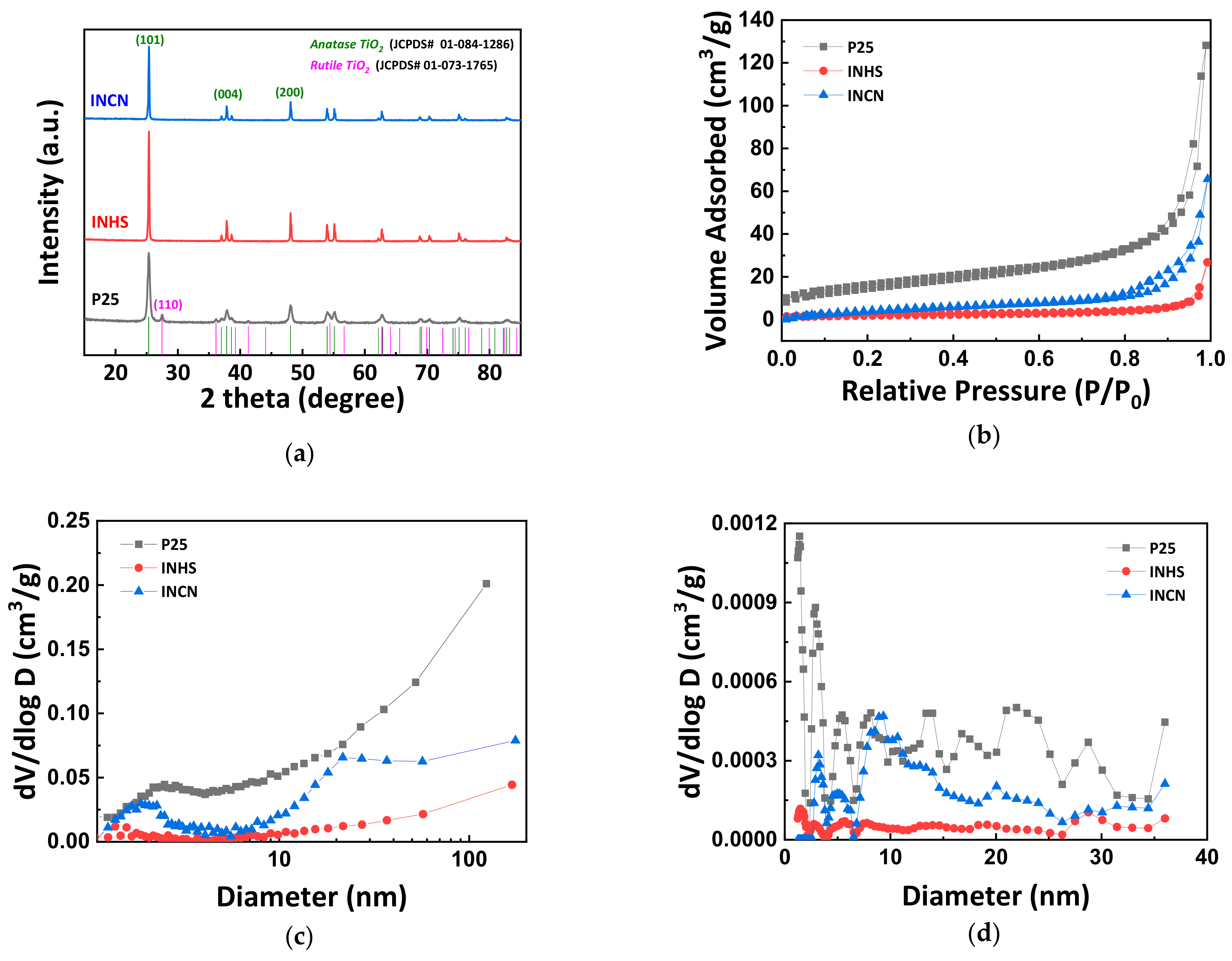
2.1. XRD and BET Results

Figure 1a presents pre (INHS), and post (INCN) modified X-ray powder Diffraction (XRD) patterns of anatase TiO2 NPs with Al(OH)3 and organosilane (R-(CH3)3-SiCl) coating. The XRD patterns were also contrasted with the commercially accessible P25 composed of anatase (70–80%) and rutile (20–30%). In the XRD pattern of INHS NPs, the diffraction peaks representing the anatase crystal structure TiO2 (JCPDS# 01-084-1286) are identical to the XRD pattern of modified INCN NPs. For example, peak diffraction peaks at the Miller indices (101), (004), (200), (105), and (211) of the TiO2 anatase crystal were observed at d-spacings of 3.520, 3.378, 1.892, 1.699, and 1.666 Å [48,49,50]. The modification, therefore, has little impact on the INHS’s crystal structure. At Miller index (101), the crystal sizes (D) of synthesized particles are calculated using the Scherrer equation and presented in Table 1 [51]. The D value of P25 is deemed to be lower than those of unmodified TiO2 (INHS). Interestingly, the integration of Al(OH3) and organosilane coating did not change the NPs’ crystal size. The D values of the NPs analyzed are thus, of the order of P25 (32 nm) < INHS ~ INCN (64 nm).
Because of improved adsorption of reactant molecules and rapid transport of reactant molecules and by-products, photocatalysts with high specific surface areas and high pore volumes help increase photocatalytic efficiency. Therefore, the porous structure of P25, INHS, and INCN was contrasted by N2 sorption analysis (Figure 1b–d). Typical IV nitrogen adsorption branching with an H3 hysteresis loop are seen in the adsorption-desorption isotherms of P25, INHS, and INCN at relative pressure between 0.5 and 1.0, suggesting the existence of a mesoporous structure [52]. Figure 1c,d demonstrate the pore size distribution of the corresponding samples determined by the Barrett-Joyner-Halenda (BJH) and Non-Local Density Functional Theory (NL-DFT) method extracted from the adsorption branch. Compared to P25 (52 m2/g), INHS (8.4 m2/g) displayed a comparatively low specific surface area owing to very large crystal size. INCN demonstrated a significant improvement in surface area to 19.9 m2/g while possessing a similar crystal size. Therefore, the overall sample pore volumes are in the order of INHS (0.02 cm3/g) < INCN (0.08 cm3/g). This finding suggests that hydrophobic coatings’ formation may be an efficient way for photocatalytic pigments to reach a large surface area. Perhaps, the increase of specific surface area can be caused by the cover of Al(OH)3 and organosilane on the surface of INHS, which may significantly increase the roughness of the coated particles.

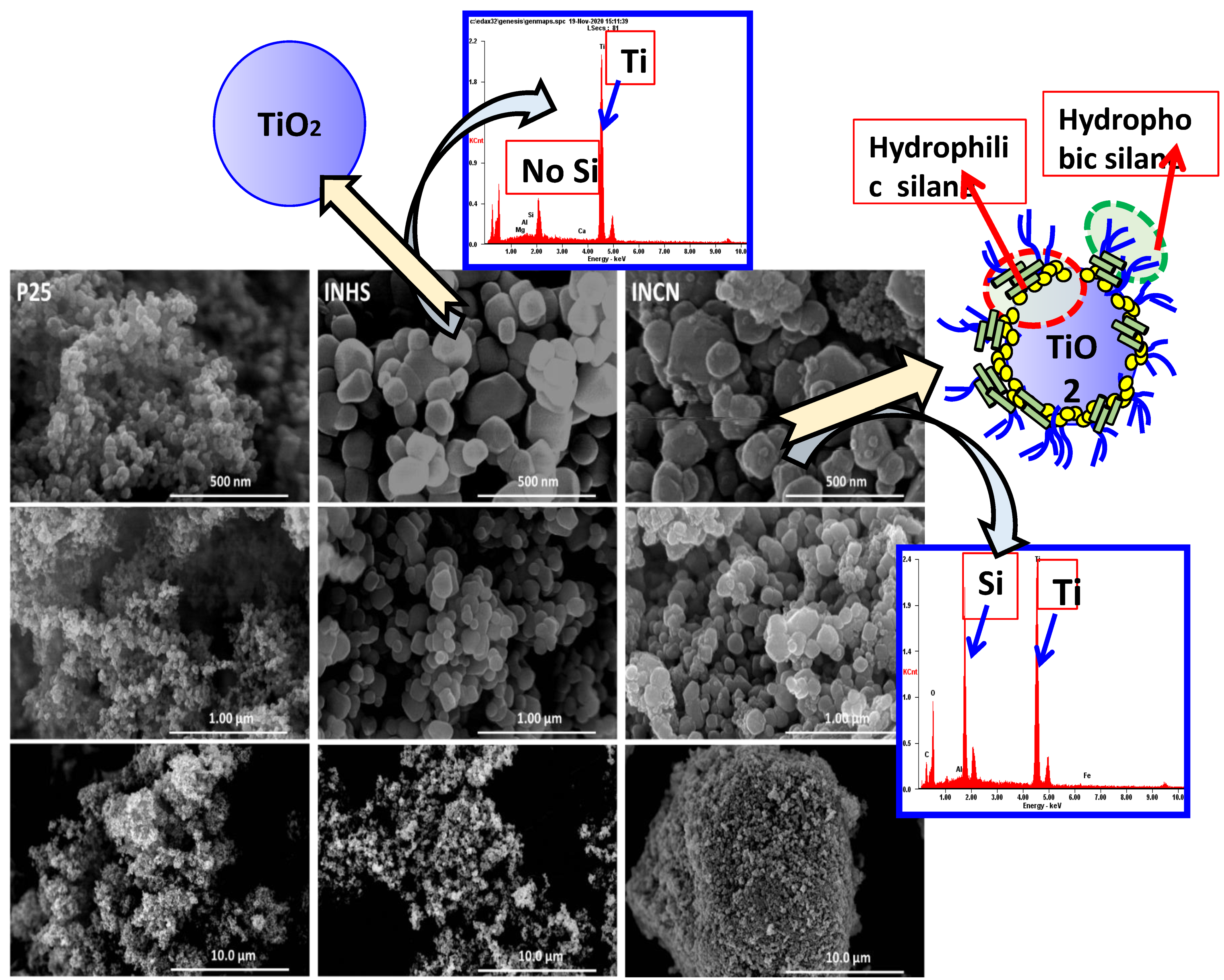
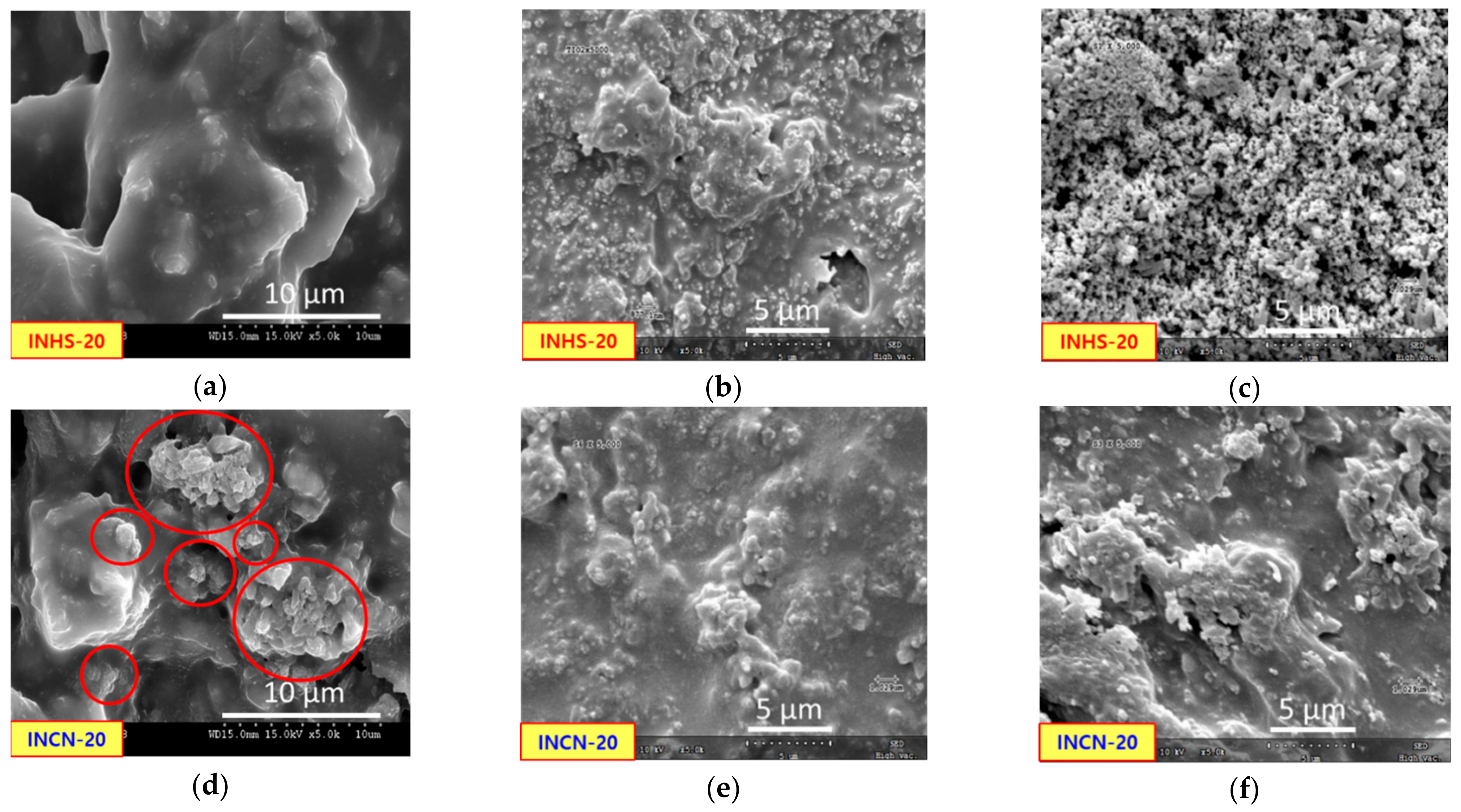
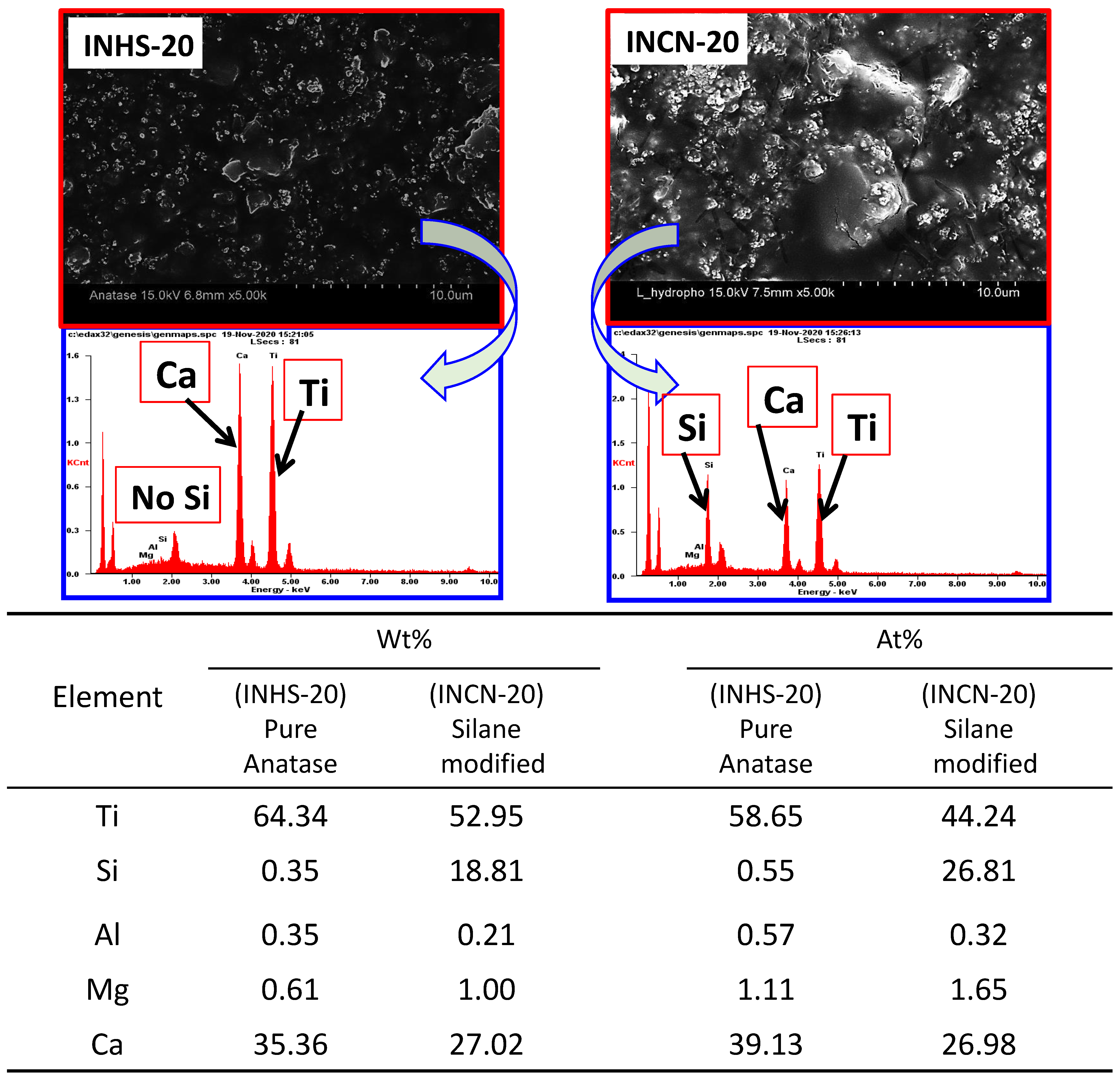
2.2. SEM and EDS Results of the NPs

Scanning Electron Microscopy (SEM) representations of P25, INHS, and INCN are shown in Figure 2 at various magnifications. The particle size of P25 is about ~50 nm, in line with the XRD findings, while the size of INHS and INCN ranged from 150 to 250 nm, and they were agglomerated together. The altered TiO2 NPs (INCN) size and shape are close to that of INHS. This suggests that the shift in size and shape of TiO2 NPs will not be induced by both hydrophilic and hydrophobic silanes grafting. Figure 2 also shows the Energy-Dispersive X-ray Spectroscopy (EDS) results of INHS and INCN (before/after modification of silanes). The altered TiO2 (INCN) size and shape are close to precursor anatase TiO2 (INHS). Furthermore, the separated NPs could be found without covering of thick agglomerated layers of silanes after modification, indicating a successful uniform coating of silica layers on the surfaces of INHS. However, the INCN sample (Figure 2) was treated with a water glass to form the silanols instead of Al(OH)3, showing no peak of Al on EDS spectrum.

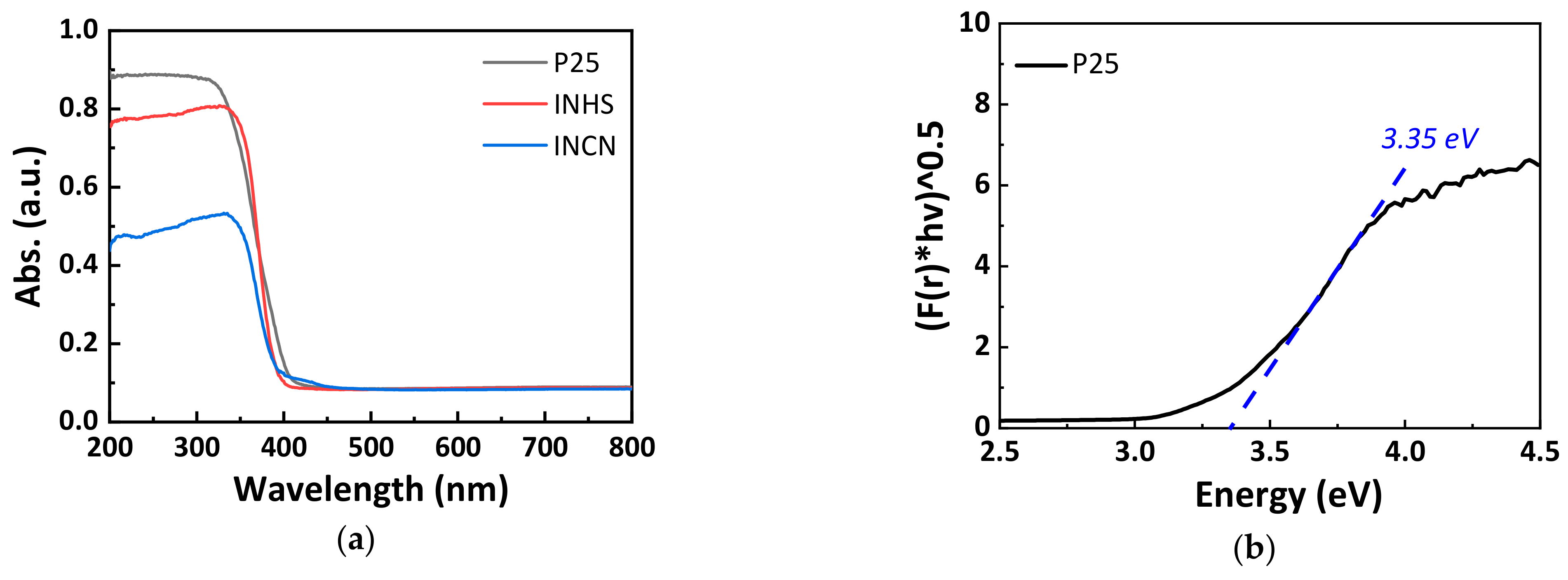
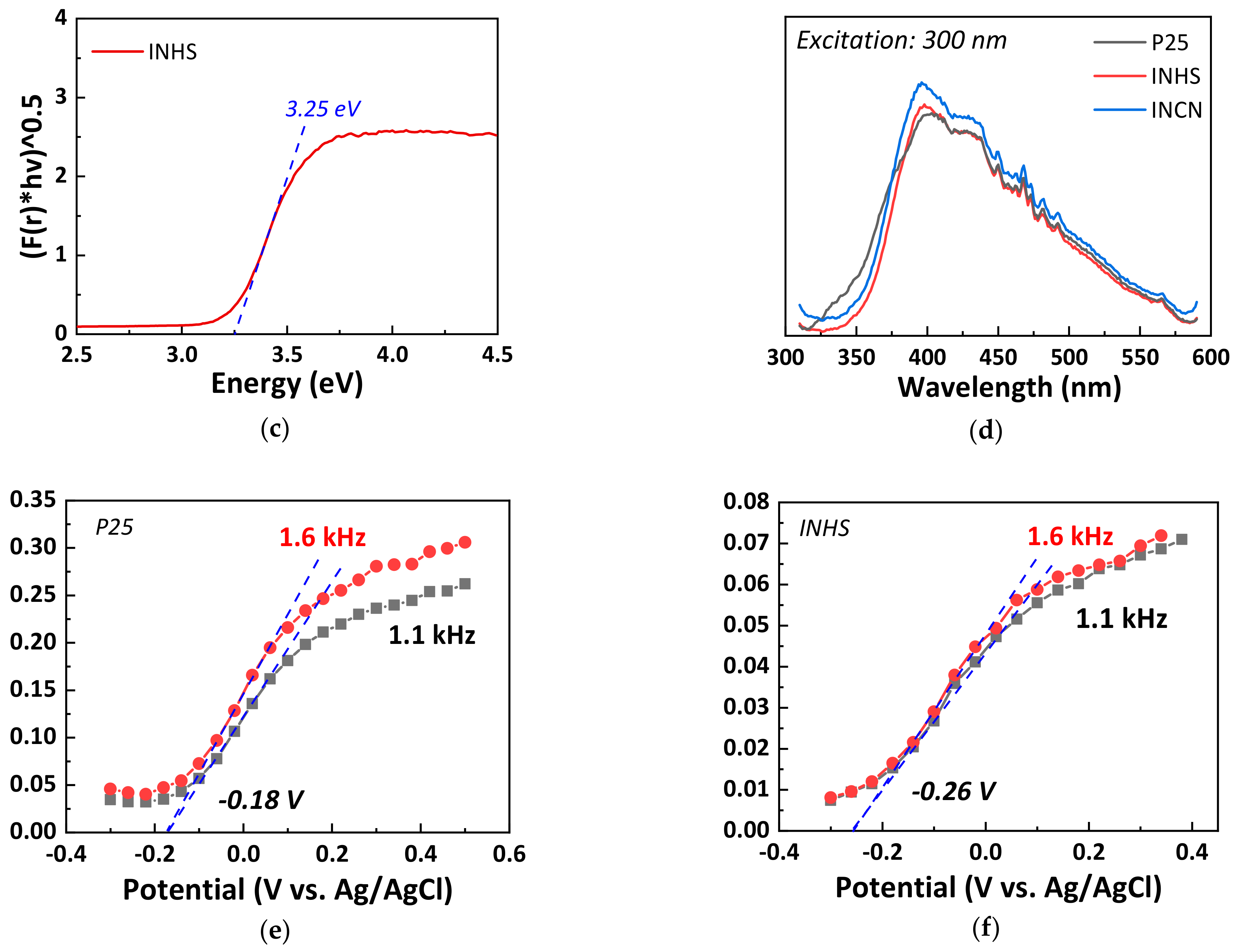
2.3. Optical Properties

Figure 3a–c display the estimated UV-Vis Diffuse Reflectance Spectroscopy (DRS) spectra and the estimated absorption pattern of P25, INHS, and INCN. Intercepts of the extrapolation lines and the energy axis [48,53] show that the P25 and INHS energy bandgap (Eg) is respectively 3.35 eV (Figure 3b) and 3.25 eV (Figure 3c). The absorption band edge of the INHS sample is about 350 nm, which is the typical value for TiO2 anatase. Compared to P25, the absorption of light in INHS is more expanded to the lower photon energy regions by about ~10 nm. In addition, an absorption range close to that of the parent INHS is shown by INCN. Due to the surface coating (or screening), the primary absorption around 350 nm decreases by 30%, although its band edge or bandgap stays unchanged after functionalization [54]. Also, the reduced UV absorption could be attributed to the lower mass composition of TiO2 in INCN. Mott-Schottky experiments further tested the electronic structure of the components [51]. The emission spectrum of the INHS sample is centered on 400 nm and resembles that of P25 in terms of intensity and peak position (Figure 3d). We note that absorption extension in the INHS sample is little reflected on the emission spectrum. This probably indicates that the difference in absorption was a result of the scattering effect. Again, the optical property of the INHS sample remains intact before and after functionalization.
The Mott-Schottky estimations were plotted (Figure 3d,e) for each sample at two frequencies above 1 kHz (1.6 and 1.1 kHz), as stated in the materials and methods section. The Mott-Schottky study provides details on a flat band potential that is considered as a CB for semiconductors of n-type. The straight lines drawn by the experimental results at various frequencies in P25 and INHS crossed the potential axis at a similar point with VFB. The positive slope of the Mott-Schottky plot reveals the semiconduction feature of the TiO2 samples of n-type. Moreover, for the INHS study, the x-intercept offers a flat band potential of −0.26 V (vs. Ag/AgCl at pH 6), which is more negative than that of P25 (−0.18 V vs. Ag/AgCl at pH 6). In conjunction with the following equations, CB and VB potential for P25 and INHS is measured against Normal Hydrogen Electrode (NHE) at pH 6 [51,55].
V CB V FB NHE ,   pH   6 = V FB Ag AgCl ,   pH   6 + Δ V
V VB = V CB + E g
where ΔV = 0.19 eV is the potential of Ag/AgCl against NHE; thus, the INHS VCB is calculated to be −0.07 eV, which is 0.01 eV for P25. The change of the INHS VCB to more negative values indicates an improvement in the capacity of the CB electrons to maximize the formation of ·O2 superoxide radicals, as the gap between the VCB and the standard O2/·O2 redox potential (−0.33 V vs. NHE) decreases [56,57]. However, as the VCB values become more negative, and the Eg values decreased in INHS, the VVB values shifted to less positive values. As a consequence, the VVB value of INHS is closer to the standard redox potential of OH/·OH (1.99 V vs. NHE) in comparison to P25 [57,58]. Therefore, the oxidation power of VB holes in INHS is reduced relative to P25 to the production of ·OH radicals.

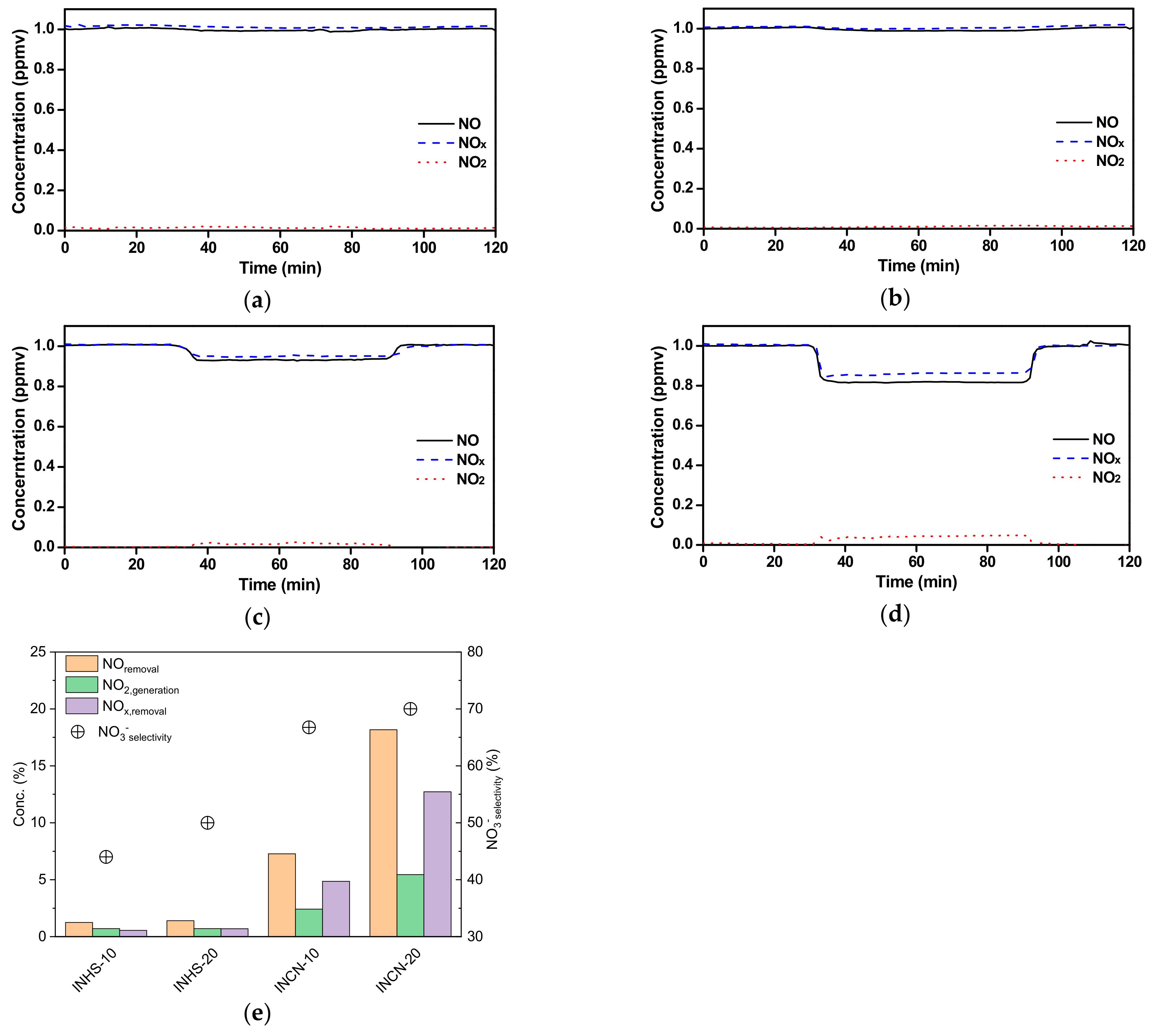
2.4. Photoactivity (NO Removal)

By assessing the degree of NO degradation through UV irradiation, the resulting specimen’s photoactivity was analyzed. Furthermore, the photocatalytic efficiencies of the powder samples were contrasted with those of the coated INHS-10, INHS-20, INCN-10, and INCN-20 samples. All the NO removal tests were performed for 120 min, and after 30 min, the lamp was turned on and sustained for 1 h. Experiments have been performed in triplicates, and the average values are recorded in this analysis. The rates of NO removal, NOx removal, NO2 generation, and nitrate (NO3) selectivity were calculated using the following equations:
NO removal =   NO in NO out NO in   × 100
NO 2 , generation =   NO 2 , out NO 2 , in NO in   × 100
NO x , removal =   NO x , in NO x , out NO in   × 100
NO 3 selectivity =   NO x , removal NO removal × 100
The NO, NO2, and NOx concentration patterns along with NO removal and NO2 generation NO3 selectivity of the coated samples (i.e., INHS-10, INHS-20, INCN-10, and INCN-20) under 1 h of UV irradiance (λ < 420 nm) are shown in Figure 4. Moreover, in Table 2, the full findings of overall NO removal after 1 h of light irradiation are provided. 7.407 ± 0.065 μmol NO was injected into the reactor in each experiment, and all the powdered samples displayed a similar NO removal profile. The NO and NOx concentrations began to decrease for all the photocatalysts tested immediately after UV light initiation and reached the minimum concentration of NO and NOx within 5 min of light irradiation. Due to the instrument’s default configuration arrangement, marginal response lag was noticed at the start and end of the light irradiation. At the beginning of light irradiation, the accelerated oxidation of NO may be due to the dual effects of adsorption and photooxidation on the photocatalytic sites of the corresponding catalysts. Later, the NO removal efficiencies appear to decrease progressively due to the photocatalytic sites’ saturation with protoxidized by-products (i.e., NO2, NO3).
Within 1 h of UV irradiation, commercially accessible P25 has taken out 3.02 μmol NO, comprising about 40.40% of the overall NO injected in the reactor. On the other hand, with the same configuration, INHS demonstrated about 44.80% NO elimination under UV light. As Table 2 indicates, due to the -OH and organosilane coating on INHS, the modified sample INCN under UV irradiation displayed a substantial decrease in NO removal (19.20%). Based on the term NO3 selectivity, we can comment on the NO to NOx conversion efficiencies. Figure 4e shows that the NO3 selectivity of the INCN-based coatings was substantially high compared to commercial INCH-based coatings. The maximum NO3 selectivity was found in INCN-20, which showed a NOx removal of 12.72% after 1 h of UV irradiation. Consequently, the NOx removal of INCN-based coatings was found superior. Presumably, the enhanced specific surface area and partial hydrophobicity of the as-prepared INCN played a crucial role in increasing the NO3 selectivity compared to commercially available anatase INHS products.
Additionally, in the case of the coated samples, compared to INHS incorporated paint, INCN-based paints showed significant improvement in NO removal. Subsequently, INCN-10 and INCN-20 removed around 7.28% and 18.17% of NO under 1 h of UV irradiation, which is approximately 6 and 13 times higher compared to INHS-10 and INHS-20, respectively. Despite the reduced NO removal capacity of INCN compared to INHS in powder form, the superior NO removal capacity of the coated surface could be ascribed to the superior dispersion of the INCN NPs in the painted surface due to the presence of the superhydrophobic and partially hydrophilic coating. Moreover, with only a 10% increase in the wt.% of INCN in the photocatalytic paint (INCN-20), the NO removal performance increased by 2.5 times.

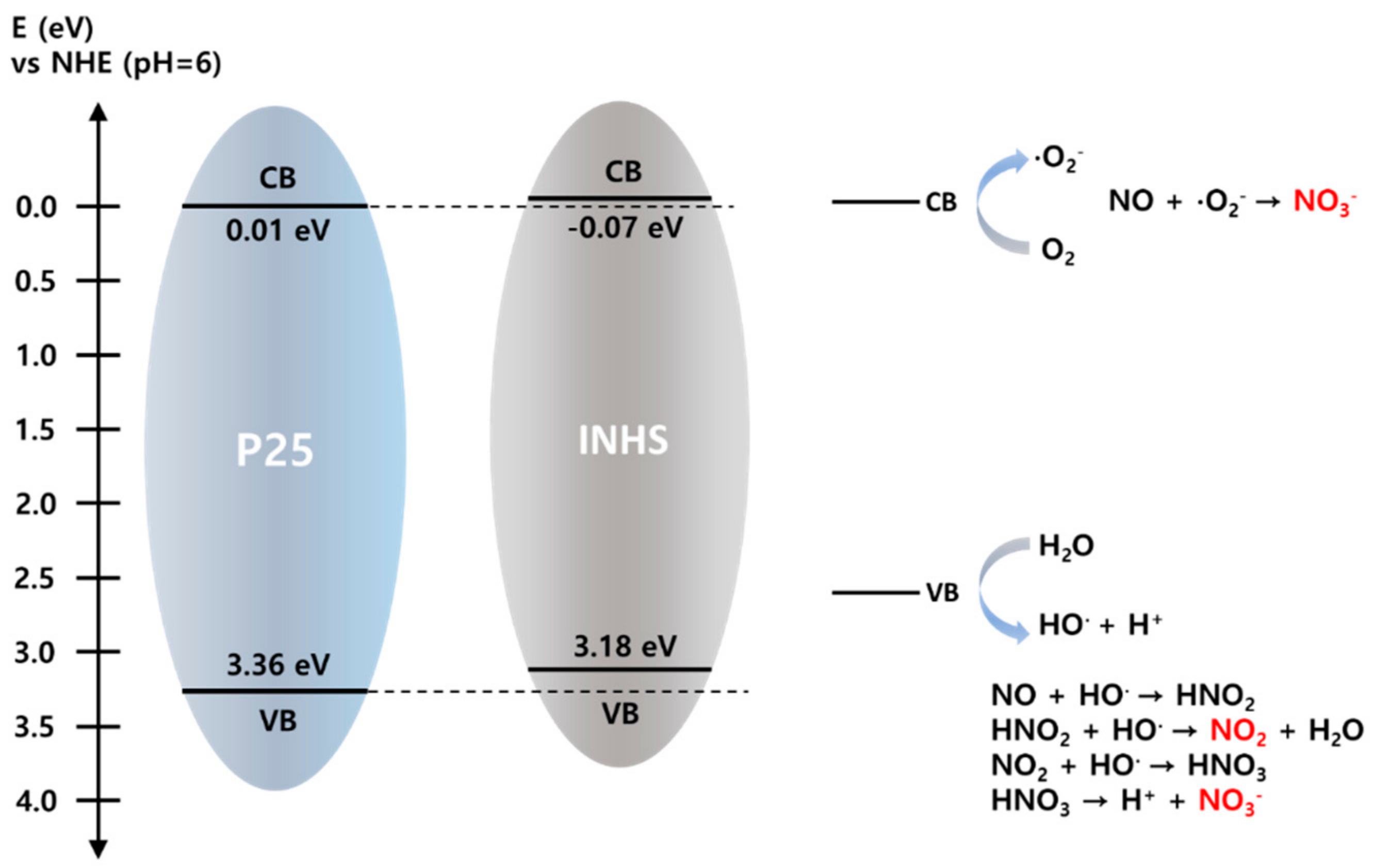
Mechanism of NO Removal

Photooxidation of NO on the samples analyzed (P25, INHS, and INCN) can be divided into four stages, i.e., [21,56,57,58,59]:
(1)
Mass transport and adsorption of ambient reactants on the specimens.
(2)
Formation of reactive species.
(3)
Succeeding photooxidation and development of the adsorbed by-products.
(4)
Desorption and mass transport of the produced by-products from the surface of the specimens.
To date, the photocatalytic oxidation process has been thoroughly studied. It is generally accepted that photocatalytic NO oxidation is mainly made up of active species such as ·O2 and ·OH radicals that are produced by redox reactions comprising the photogenerated e/h+ sets and adsorbed O2 and H2O on the photocatalysts [57,60,61]. The mechanism to NO oxidation over anatase titanium used in this analysis can be expressed as follows based on the relevant studies:
(a)
Mass transport and adsorption of ambient reactants on titania.
X + NO N ad X O ;   X = P 25 / INHS / INCN
X + H 2 O H ad X 2 O
X + O 2 O ad X 2
(b)
Formation of reactive species:
X + h ϑ e +   h +
e + O ad X 2   · O 2
h + + H ad X 2 O   · OH
(c)
Photooxidation and development of the adsorbed N-based by-products:
· O 2 + N ad X O N ad X O 3
· OH + N ad X O N ad X O 2
· OH + NO 2 H ad X NO 3 + H +
(d)
Desorption and mass transport of the produced by-products from the surface of the titania:
H ad X NO 3 X + HNO 3
N ad X O 2 X + NO 2
It is clear from these equations that the adsorbed O2 and H2O play a very significant role in the photooxidation of atmospheric NO. During photooxidation, O2 is employed to trap the generated e on the TiO2 surface, and ·OH radicals are formed from H2O by confining the generated h+ on the TiO2 surface, leading to NO oxidation and produce by-products like NO2 and NO3 [14,15]. Therefore, when the sample is subjected to UV radiation, the photooxidation of NO takes place spontaneously. Later, the concentration of NO2 rises and reaches a stable state rapidly, and after attaining the maximum decay point, the oxidation rate diminishes marginally and reaches a stable conversion condition. Figure 4 indicates the change in the concentration of NOx during photocatalytic oxidation reactions. Nevertheless, not all the processed NO2 can be oxidized to NO3 owing to desorption; a tiny portion is emitted into the environment. Besides, the photooxidation potential of the generated reactive species is different. A number of studies claimed that compared to ·OH, ·O2 is superior in oxidizing NO to NO3 [14,56,57]. Thus, the exit pollutant comprises of the residual NO, the undesired NO2, and the NO3.
The CB edge of the photocatalyst has to be more negative relative to the redox capacity of O2/·O2 (0.33 eV vs. NHE) for the photogenerated e to generate ·O2 efficiently. On the other hand, the standard redox potential for the OH/·OH is 1.99 eV versus NHE; thus, for the h+ to produce ·OH radicals, the location of VB must be more positive. For this analysis, P25’s CB and VB edges are measured at +0.01 and +3.36 eV (NHE, pH 6), respectively, while INHS’s are roughly at −0.07 and +3.18 eV. In Figure 5, a basic diagram with NO photooxidation was suggested based on the approximate CB and VB locations of P25 and INHS. Due to favorable optical band position, both P25 and INHS could be excited under UV light irradiation and could produce photogenerated e/h+ pairs, as seen in Figure 5. Later, the photogenerated e promptly creates ·O2 by interacting with the adsorbed O2, whereas h+ on the VB can oxidize H2O/OH to ·OH radicals directly. The ·O2 radicals have been presumed to be the primary component for the effective oxidization of NO to NO3 [57,62]; in addition, compared to P25, the CB edge of INHS was more negative. Hence, the ·O2 generation potential of INHS was higher, so as the total NO removal. Moreover, despite having a large crystal size and significantly small effective surface area, INHS showed a notable photooxidation rate of NO, which may be associated with the narrowed optical bandgap compared to P25. On the other hand, the modified INHS (INCN) showed an inhibited NO removal rate compared to the precursor (INHS), even though the effective surface area was substantially enhanced due to the increased roughness of the surface. The reduced NO removal of INCN could be assigned to the dual effect of (a) entrapment of photogenerated e/h+ pairs on the prevailing coating (TEOS and organosilane) and (b) 30% reduced light absorption within the UV spectrum. Interestingly, while the photocatalytic coating was prepared separately using INHS and INCN in water-based paint, the photooxidation rate of NO over the coated surface got overturned. Due to the presence of -OH functional groups and superhydrophobic silane coating on the surface of INCN, the dispersity of and buoyancy of the photoactive titania substantially enhanced in the paint solution [44,54]. Hence, the active surface area on the INCN coated surfaces significantly increased compared to INHS coated surfaces, so as the removal rate of NO.

2.5. Morphology of the Coated Surface and Durability

Based on the SEM findings, Figure 6a clearly demonstrates the surface with a certain nanometer-scale roughness consisting of INHS NPs. However, when INHS is combined with paint, a substantial portion of the photocatalysts are coated with paint. Therefore, even though a significant volume of INHS is used, the photocatalytic efficiency is not observed. In the case of INCN photocatalytic paint, the hydrophilic/hydrophobic part is present, and the photocatalytic portion is exposed to show photocatalytic performance. As shown in Figure 6d, the INCN NPs surface with a self-assembled monolayer coating is acquired by chemical modification of Si(OH)x and organosilane on the surfaces of anatase INHS. In addition, the surface-modified INHS particle surface is shaped into larger agglomerates in INCN-20, and it is evident that microstructures with an additional roughness regime are observed. The precursor INHS NPs’ surface probably had several -OH functional groups and was hydrophilic and immersed in water-based paint. In this research, we tried to alter TiO2 NPs by Al(OH)3 (or by silanols (Si(OH)x) and R-(CH3)3-SiCl, which, due to the presence of the C-H units, can effectively reduce the surface free energy of INHS NPs; thus, it can substantially increase the dispersion of INCN NPs in organic solvents and avoid agglomeration/settling of the INHS. The updated INCN NPs thus floated on the top of the painted surface, showing that after alteration, the surface properties of the INHS dramatically changed. The silane coupling agent hydrolyzed O-CH3 groups, and reactive silane triols were generated and later condensed to form oligomers that were adsorbed on the surface to form bond linkages with the facade -OH groups, resulting in a silane coupling agent that is chemically bound on the surface of the precursor INHS.
The durability of the photocatalytic coatings (INHS-20 and INCN-20) was tested by using exposure to UV irradiation for 2 weeks. A significantly high UV intensity of 350 W/m2 was implemented. Figure 6b,c,e,f showed the before and after SEM images of the durability tests on the paint coating developed by incorporating INHS-20 and INCN-20, respectively. From the before (Figure 6b) and after (Figure 6c) images of INHS-20, it is evident that many particles are formed on the surface under UV exposure conditions of 2 weeks due to the photodegradation of the organic portion of the utilized paint, causing choking phenomenon. On the other hand, the before and after image of INCN-20 showed a minimal change, which proves that the synthesized INCN can minimize the so-called choking phenomena through superhydrophobic and partial hydrophilic coating in the photocatalyst’s surface, which eventually prevents the photocatalysts (INCN) from getting in contact with the organic part of the paint.
In the SEM image of Figure 7, the vividly shining part shows the TiO2 photocatalyst particles exposed to the outside. In the hydrophilic INHS, without any treatment, most of the particle surfaces are covered by the hydrophilic acrylic binder. In the case of coated INCN, it can be interpreted that due to the presence of hydrophobic coating, many parts are exposed on the surface and showed high photocatalytic activity even after the paint film is completely dried. The large particles in the SEM image are CaCO3 powder, and the mixing ratio of TiO2 and CaCO3 was 1:1 by wt.% when making the photocatalytic paint, and the composition ratio can be seen in Figure 7. In addition, as can be seen from the EDS spectra, the INHS-20 sample does not contain a silica component, and in the case of INCN-20, about 36 wt.% of silica is coated.

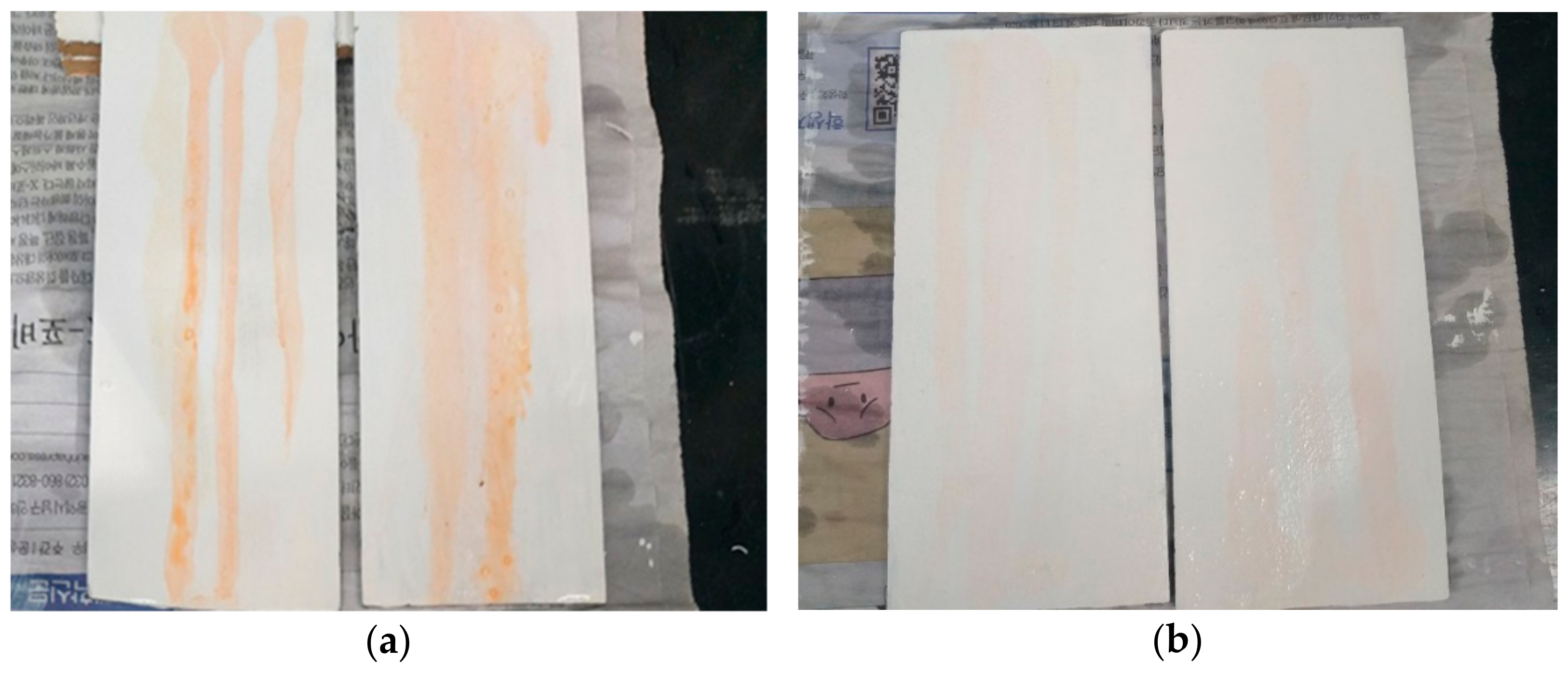
2.6. Self-Cleaning Properties

The photocatalytic paint INCN-20 showed good self-cleaning properties when applied on a ceramic substrate. The self-cleaning property was tested by spraying oil on the treated film under weak UV conditions and subsequent washing. To the ‘authors’ knowledge, the majority of self-cleaning superhydrophobic coats are used mainly for hydrophilic pollutants and not for oils, as oils typically result in superhydrophobicity failure. This phenomenon happens because of the lower surface tension of oil than that of water, which allows the oil to reach the surfaces. The self-cleaning tests of the painted surfaces after oil spraying and subsequent washing are presented in Figure 8. As shown in Figure 8a, with the general paint in the absence of INCN, the top surface of the coated glass substrate became contaminated from the oil spraying, and after washing, the oil spread on the surface of the coating by compromising the self-cleaning property. On the other hand, Figure 8b depicted the superior self-cleaning property of INCN-20 after the oil spraying test.
The dual effect of the following phenomena could be the reason for the superior self-cleaning attribute of the INCN-20 coating, viz., (a) superoleophobicity, generated from the extensive roughness formation on the surface of the INHS NPs due to silane coating, and (b) due to partial hydrophilicity of the INCN, the oil could penetrate through the coating and may get decomposed by underlaying INHS under weak UV exposure. The INCN NPs may thus, on the one hand, create the necessary rough covering for superhydrophobicity and, on the other hand, remove organic pollutants with photodegradation and, therefore, may provide durable self-cleansing and photoactive properties for coatings.

3. Materials and Methods

3.1. Chemical Reagents

Tetraethyl orthosilicate (TEOS; 98%), propyltrimethoxysilane (98%), triethoxy(octadecyl)silane (90%), trimethylchlorosilane (98%) and triethoxy(dodecyl)silane (90%) were purchased from Sigma-Aldrich (Seoul, Korea) and n-octyltriethoxysilane (95%) was from Tokyo Chemical Industry (TCI, Chuo city, Tokyo, Japan). Anatase type TiO2 photocatalyst (INHS) was supplied from Photo-Environmental Co. (Daegu, Korea). HCl (35%), ethanol (98%), Al2(SO4)3 (<90%), sodium silicate solution (water glass, CP grade) and CaCO3 (<95%) powder were purchased from Duksan Pure Chemicals Co., Ltd. (Ansan-si, Korea). The acryl type emulsion binder (45 wt.% concentration in water) was synthesized and supplied from Hansong Industry Co. (Gwangju, Korea), and it was used for the preparation of the paint containing photocatalysts.

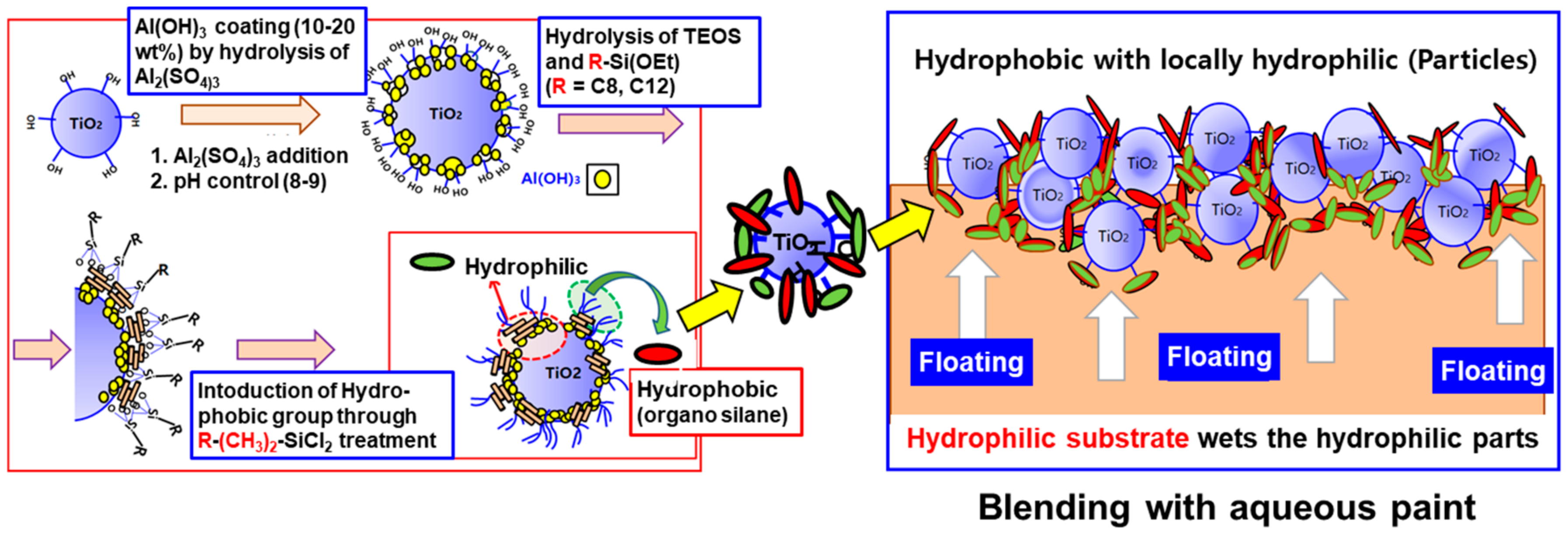
3.2. Preparation of Photocatalytic Paint

Initially, specific amounts of anatase TiO2 (INHS) NPs were well dispersed in deionized water and ethanol with the help of ultrasonication for 10 min. The ethanol content of the dispersion was twice that of INHS, and the wt.% of water was maintained at 40% of INHS. Then 3–7 wt.% of Al2(SO4)3 was added to the dispersion to employ the Al(OH)3 coating (or The silanols (Si(OH)x) were coated on the surfaces of anatase INHS by water glass coating and pH adjustment at 5–6). Besides, TEOS and R-Si(OEt)3 (R = (CH2)7CH3, or (CH2)11CH3)) were added to the dispersion at 20 wt.%, and 30 wt.% corresponding to the utilized INHS NPs. HCl was used to maintain the pH of dispersion within the range of 4–5. Later the dispersion was stirred well and kept for six h for hydrolysis and the formation of a coating on the surface of INHS NPs. Then, (CH3)3-Si-Cl was hydrolyzed to hydrophobically coat the surface of INHS NPs to prepare the composite photocatalyst. At this time, (CH3)3-Si-Cl corresponding to 10% to 30% of the weight of the TiO2 powder was added, stirred, and reacted at room temperature for two h to adjust the hydrophobicity of the INHS surface. From here on, the coated INHS NPs generated in this study are termed as INCN. Figure 9 depicted the simple schematic for the fabrication process of the INCN.
To maintain the proper surface hydrophobicity, the amount of (CH3)3-Si-Cl added was adjusted by observing the degree of precipitation or suspension of the obtained INCN NPs in the water. To maximize the degree of exposure to the surface while maintaining the strong bonding strength with the paint, it is necessary to keep the hydrophilic and hydrophobic regions at an appropriate ratio on the surface. To this end, the appropriate weight ratio of the total weight of alkyl silane and trimethylchlorosilane was adjusted to a ratio of 1:1. After completing the coating process, the modified INCN NPs were dried in an oven for 24 h at 100 °C and cooled to room temperature. Since INHS has few hydrophilic portions on the surface, TEOS was coated with an organic silane having an extended alkyl group as a hydrophilic group and TEOS as a hydrophobic group. When these two silane mixtures are hydrolyzed and coated on the surface of INHS, a portion containing a large amount of TEOS becomes hydrophilic, and a portion containing an alkylsilane becomes hydrophobic. Therefore, the hydrophobic part repels the hydrophilic paint component and induces the paint to bind to the hydrophilic group. If there are numerous hydrophobic groups, the water-soluble paint is repelled during drying, resulting in many photocatalyst particles being exposed on the surface of the paint’s outer surface. Typical photocatalyst-containing paints are prepared by mixing INHS or INCN NPs with a water-soluble acrylic binder and CaCO3 powder in a weight ratio of 1:1, and coating on a ceramic plate, and drying at room temperature for 24 h to oxidize NO under UV irradiation. The wt.% of photocatalytic NPs (INHS and INCN) were varied as 10% and 20% in the synthesized paint samples and labeled accordingly as INHS-10, INHS-20, INCN-10, and INCN-20.

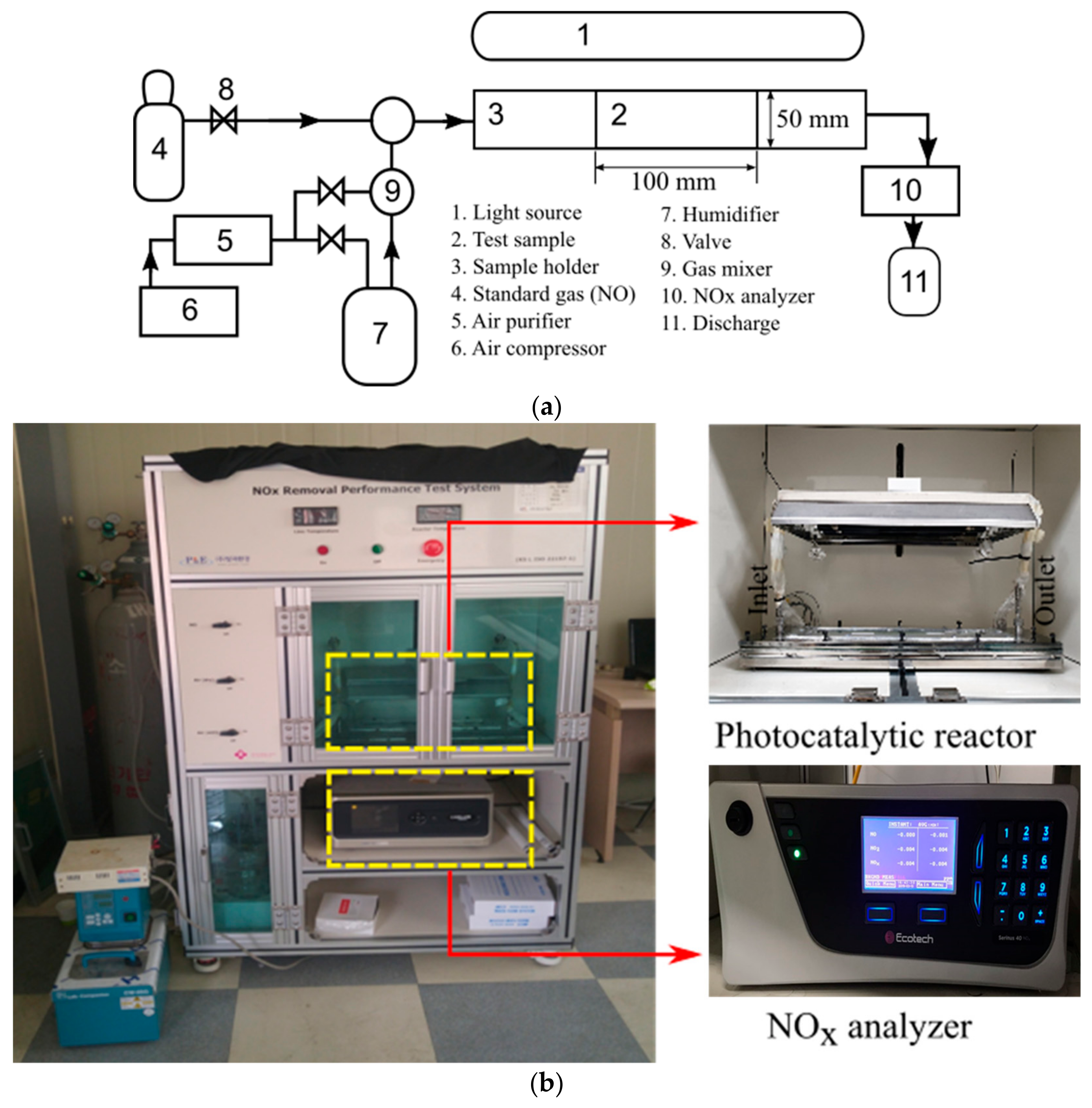
3.3. Photocatalytic Performance Analysis

Removal of NOx under UV Irradiation

The removal efficiency of NOx (NO and NO2) was assessed for modified powdered samples and modified NP induced paint-coated solid substrate. The findings were compared with INHS and P25 in both instances. All the samples were pre-treated with 10 W/m2 ± 0.5 W/m2 UV irradiation for five h, by using two 10 W UV-A (Sanyo-Denki, Nagano, Japan) lamps. A laboratory-scale photocatalytic reactor was used, following ISO 22197-1, to examine the extent of NOx photooxidation. The specifics of the method are listed elsewhere [14,15,16]. Figure 10 shows the diagram of the device used to test the photocatalytic efficiency of the as-prepared samples. Following the ISO protocols, the used photoreactor could carry a test sample with a width of 50 mm with a surface parallel to the photoirradiation optical window. The sample piece was isolated from the glass by a 5 ± 0.5 mm thick sheet of air. The distance was closely regulated by the use of height adjustment frames.
In short, a rectangular mold with a surface area of 50 cm2 was used to position the powder sample in the photocatalytic reactor, and 3 g of NPs was pressed into the holder. A steady airflow of 3 L/m comprising 1 ppm of NO was maintained via the inlet of the reactor. The reactor humidity content and temperature were set at 50% and 25 °C, respectively. To test the variation of NOx concentration during the experiment, a NOx analyzer (CM2041, Casella, Buffalo, NY, USA) was placed at the reactor’s outlet. A steady flow of 1 ppm NO was initially sustained for 30 min without any UV irradiation. The UV-A lamps were turned on after 30 min, and the NOx concentration was recorded in the NOx analyzer for 60 min. Likewise, the prepared paint-coated ceramic (100 mm × 50 mm × 10 mm) were put in the holder of the test specimen, and the concentration of NOx (NO, NO2) was recorded under UV irradiation for 60 min.

3.4. Morphological Characterization and Durability Analysis

The crystalline structure of the samples was characterized by XRD analysis by producing XRD patterns on an MDI Jade 5.0 X-ray diffractometer (D/MAX Ultima III, Rigaku, Tokyo, Japan) with 40 kV and 40 mA Cu Kα radiation. The XRD pattern was noted down in the 2θ range from 2° to 90° at a 0.02/s scanning rate using the Bragg-Brentano experimental process. 2/3° divergence, 10 mm divergent length, 2/3° scattering, and 0.3 mm receiving slits were the X-ray laser’s controlling parameters.
SEM (S4-4700, Hitachi, Tokyo, Japan) was used to analyze the morphology of the powdered and coated materials, set to 10 kV in a vacuum at a working distance of 7 mm. Using the EDX detector (55VP SEM), operating at 10 kV, the fundamental structures were assessed. To evaluate the samples’ fine morphological details, a field emission transmission electron microscope (FE-TEM, JEOL Ltd., JEM-2100F, Tokyo, Japan) was used at 200 kV. The N2 adsorption-desorption isotherm of the samples was collected at 77K using a gas adsorption analyzer (ASAP 2020, Micromeritics, Norcross, GA, USA). A multi-point BET method at P/P0 = 0.1–0.2 and a single point method at P/P0 = 0.99 were used to estimate the surface area and pore volume, respectively. The BJH model with the adsorption isotherm was used to calculate pore size distribution. A microplate fluorometer (Dual FL, Horiba, Piscataway, NJ, USA) was used to generate the solid-state NP emissions range, which was historically generated by a 300 nm wavelength of excitation. A UV-Vis-NIR spectrometer (Lambda 950, Perkin Elmer, KBSI Daegu Core, South Korea), fitted with a diffuse reflectance accessory, was used to procure UV-Vis spectra. The spectra were observed in a spectrum of 400–800 nm at a scan rate of 600 nm/min. To figure out the optical bandgap of the prepared samples, the Kubelka-Munk function (F(R)) was used (see Equations (18)–(20)). The optical bandgap measurement was performed by extrapolation from the plott of (F(R)hυ)1/2 vs. hυ, where:
R = K S
K = 1 R 2
S = 2 R
Here, K is the molar absorption coefficient, S is the scattering factor, and R is the reflectance data from the DRS analysis.
The sample’s electrochemical output was analyzed by the VSP potentiostat (Bio-Logic Science Instruments, Seyssinet-Pariset, Isère, France) with EIS capability provided with a three-electrode beaker style cell. The TiO2 coated FTO glass, Pt coil, and Ag/AgCl KCl (3M) electrode was respectively used as the working, counter, and reference electrodes. The slurry solution of TiO2 samples was prepared as follows: initially, 10 mg of the studied material was disseminated in 5 mL of pure ethanol (Aldrich); secondly, in the ultrasonic bath, the dispersion achieved was then sonicated for 30 min; finally, the GC electrode was coated with 30 μL dispersion, which was then dried for two h at 70 °C in the furnace. The electrolyte used in the calculations was 0.2 M Na2SO4 in an aqueous state. A 30 min. N2 purging was performed before the measurements. The measurements were carried out at room temperature. Electrochemical tests were used to determine the CB edge potential of the samples studied. Since the CB edge potentials and the flat band potential for n-type semiconductors such as TiO2 correlate, the Mott-Schottky relationship was used to establish this.

4. Conclusions

This study aimed to successfully prepare photocatalytically active and long-lasting paint with the help of incorporating anatase titania (INHS) through a facile mechanism. Therefore, INHS was coated with Al(OH)4 and organosilane having large alkali groups, which have introduced both hydrophilic and hydrophobic regions in the coating of modified INHS (INCN). Based on the morphological characterization, the crystal size of the assessed NPs was found in the order P25 (~32 nm) > INHS (~64 nm) > INCN (~64 nm), and the BET analysis revealed the specific surface area was in the order: P25 (~53 m2/g) > INCN (~20 m2/g) > INHS (~8 m2/g). Hence, from the morphological point of view based on the XRD, SEM, and N2 adsorption-desorption isotherms, INCN exhibited a substantial amount of roughness despite having a similar crystal size on the surface of the NPs. Additionally, the optical attributes of the INCN remained unaffected due to the incorporation of the organosilane-based coating. Compared to P25, the parent INHS NPs showed higher NO oxidation under UV irradiation due to a more negative value of the CB, facilitating generation of ·O2 radicals, which are a major contributor to photooxidation of NO. In the case of UV-based NO oxidation on INCN, the removal rate was reduced to 19.20% (half of INHS) due to the reduction in UV absorbance (30% less) because of the existing coating. However, while coated on the ceramic substrate, INCN-20 showed significant NO removal of 18.17%, which was only 1.25% for INHS-20. Consequently, due to the presence of the hydrophilic part on INCN coating, well dispersion was observed, and the hydrophobic part imported buoyancy in the NPs, cause extended exposure at the top surface of the coating. Moreover, the hydrophobic region of the coating assisted INCN in inhibiting the photodecomposition of the organic part in the utilized paint. Hence, compared to INHS-20, INCN-20 showed substantial UV endurance. Finally, the synthesized INCN-based coating showed good self-cleaning attributes even after oil spraying and subsequent washing. Hence, the proposed facile Al(OH)3 and organosilane-based modification of anatase titania could be a viable and promising approach towards the successful fabrication of durable photocatalytic paints.

Author Contributions

Conceptualization and methodology, J.-H.K., N.S., A.F., H.P. and Y.-S.J.; formal analysis, investigation and data curation, S.M.H., H.-J.K. and H.P.; writing—original draft preparation, S.M.H., J.-H.K., G.W.P. and G.-J.K.; writing—review and editing, L.T., Y.-S.J. and H.K.S.; supervision, J.-H.K. and H.K.S. All authors have read and agreed to the published version of the manuscript.

Funding

This study was supported by a Research grant from Inha University.

Institutional Review Board Statement

Not applicable.

Informed Consent Statement

Not applicable.

Data Availability Statement

Data is contained within the article.

Conflicts of Interest

The authors declare that they have no known competing financial interests or personal relationships that could have appeared to influence the work reported in this paper.

References

  1. Yang, L.; Hakki, A.; Zheng, L.; Jones, M.R.; Wang, F.; Macphee, D.E. Photocatalytic concrete for NOx abatement: Supported TiO2 efficiencies and impacts. Cem. Concr. Res. 2019, 116, 57–64. [Google Scholar] [CrossRef] [Green Version]
  2. Song, W.; Zeng, Y.; Wang, Y.; Zhang, S.; Zhong, Q.; Wang, T.; Wang, X. Photo-induced strong active component-support interaction enhancing NOx removal performance of CeO2/TiO2. Appl. Surf. Sci. 2019, 476, 834–839. [Google Scholar] [CrossRef]
  3. Schwartz-Narbonne, H.; Jones, S.H.; Donaldson, D.J. Indoor lighting releases gas phase nitrogen oxides from indoor painted surfaces. Environ. Sci. Technol. Lett. 2019, 6, 92–97. [Google Scholar] [CrossRef] [Green Version]
  4. Martinez-Oviedo, A.; Ray, S.K.; Nguyen, H.P.; Lee, S.W. Efficient photo-oxidation of NOx by Sn doped blue TiO2 nanoparticles. J. Photochem. Photobiol. A Chem. 2019, 370, 18–25. [Google Scholar] [CrossRef]
  5. Guo, M.-Z.; Li, J.-S.; Poon, C.S. Improved photocatalytic nitrogen oxides removal using recycled glass-nano-TiO2 composites with NaOH pre-treatment. J. Clean. Prod. 2019, 209, 1095–1104. [Google Scholar] [CrossRef]
  6. Giampiccolo, A.; Tobaldi, D.M.; Leonardi, S.G.; Murdoch, B.J.; Seabra, M.P.; Ansell, M.P.; Neri, G.; Ball, R.J. Sol gel graphene/TiO2 nanoparticles for the photocatalytic-assisted sensing and abatement of NO2. Appl. Catal. B Environ. 2019, 243, 183–194. [Google Scholar] [CrossRef]
  7. Luevano-Hipolito, E.; Martinez-de la Cruz, A. Photocatalytic stucco for NOx removal under artificial and by real weatherism. Constr. Build. Mater. 2018, 174, 302–309. [Google Scholar] [CrossRef]
  8. Yu, Q.L.; Hendrix, Y.; Lorencik, S.; Brouwers, H.J.H. Field study of NOx degradation by a mineral-based air purifying paint. Build. Environ. 2018, 142, 70–82. [Google Scholar] [CrossRef]
  9. Velazquez-Palenzuela, A.; Dam-Johansen, K.; Christensen, J.M. Benchmarking of photocatalytic coatings performance and their activation towards pollutants degradation. Prog. Org. Coat. 2020, 147, 105856. [Google Scholar] [CrossRef]
  10. Upton, R.L.; Crick, C.R. Pigmented self-cleaning coatings with enhanced UV resilience via the limitation of photocatalytic activity and its effects. Mol. Syst. Des. Eng. 2020, 5, 876–881. [Google Scholar] [CrossRef]
  11. Sun, S.; Ding, H.; Wang, J.; Li, W.; Hao, Q. Preparation of a microsphere SiO2/TiO2 composite pigment: The mechanism of improving pigment properties by SiO2. Ceram. Int. 2020, 46, 22944–22953. [Google Scholar] [CrossRef]
  12. Agrios, A.G.; Pichat, P. State of the art and perspectives on materials and applications of photocatalysis over TiO2. J. Appl. Electrochem. 2005, 35, 655–663. [Google Scholar] [CrossRef]
  13. Wei, B.-X.; Zhao, L.; Wang, T.-J.; Gao, H.; Wu, H.-X.; Jin, Y. Photo-stability of TiO2 particles coated with several transition metal oxides and its measurement by rhodamine-B degradation. Adv. Powder Tech. 2013, 24, 708–713. [Google Scholar] [CrossRef]
  14. Hossain, S.M.; Park, H.; Kang, H.-J.; Mun, J.S.; Tijing, L.; Rhee, I.; Kim, J.-H.; Jun, Y.-S.; Shon, H.K. Facile synthesis and characterization of anatase TiO2/g-CN composites for enhanced photoactivity under UV–visible spectrum. Chemosphere 2021, 262, 128004. [Google Scholar] [CrossRef] [PubMed]
  15. Hossain, S.M.; Park, H.; Kang, H.-J.; Mun, J.S.; Tijing, L.; Rhee, I.; Kim, J.-H.; Jun, Y.-S.; Shon, H.K. Modified Hydrothermal Route for Synthesis of Photoactive Anatase TiO2/g-CN Nanotubes from Sludge Generated TiO2. Catalysts 2020, 10, 1350. [Google Scholar] [CrossRef]
  16. Hossain, S.M.; Park, H.; Kang, H.-J.; Kim, J.B.; Tijing, L.; Rhee, I.; Jun, Y.-S.; Shon, H.K.; Kim, J.-H. Preparation and characterization of photoactive anatase TiO2 from algae bloomed surface water. Catalysts 2020, 10, 452. [Google Scholar] [CrossRef]
  17. Hashimoto, K.; Wasada, K.; Osaki, M.; Shono, E.; Adachi, K.; Toukai, N.; Kominami, H.; Kera, Y. Photocatalytic oxidation of nitrogen oxide over titania–zeolite composite catalyst to remove nitrogen oxides in the atmosphere. Appl. Catal. B Environ. 2001, 30, 429–436. [Google Scholar] [CrossRef]
  18. Devahasdin, S.; Fan, C.; Li, K.; Chen, D.H. TiO2 photocatalytic oxidation of nitric oxide: Transient behavior and reaction kinetics. J. Photochem. Photobiol. A Chem. 2003, 156, 161–170. [Google Scholar] [CrossRef]
  19. Ichiura, H.; Kitaoka, T.; Tanaka, H. Photocatalytic oxidation of NOx using composite sheets containing TiO2 and a metal compound. Chemosphere 2003, 51, 855–860. [Google Scholar] [CrossRef]
  20. Wang, H.; Wu, Z.; Zhao, W.; Guan, B. Photocatalytic oxidation of nitrogen oxides using TiO2 loading on woven glass fabric. Chemosphere 2007, 66, 185–190. [Google Scholar] [CrossRef]
  21. Yu, Q.L.; Brouwers, H.J.H. Indoor air purification using heterogeneous photocatalytic oxidation. Part I: Experimental study. Appl. Catal. B Environ. 2009, 92, 454–461. [Google Scholar] [CrossRef]
  22. Kuo, C.-S.; Tseng, Y.-H.; Huang, C.-H.; Li, Y.-Y. Carbon-containing nano-titania prepared by chemical vapor deposition and its visible-light-responsive photocatalytic activity. J. Mol. Catal. A Chem. 2007, 270, 93–100. [Google Scholar] [CrossRef]
  23. Ballari, M.M.; Yu, Q.L.; Brouwers, H.J.H. Experimental study of the NO and NO2 degradation by photocatalytically active concrete. Catal. Today 2011, 161, 175–180. [Google Scholar] [CrossRef]
  24. Liu, J.; Han, L.; An, N.; Xing, L.; Ma, H.; Cheng, L.; Yang, J.; Zhang, Q. Enhanced visible-light photocatalytic activity of carbonate-doped anatase TiO2 based on the electron-withdrawing bidentate carboxylate linkage. Appl. Catal. B Environ. 2017, 202, 642–652. [Google Scholar] [CrossRef]
  25. Aghighi, A.; Haghighat, F. Using physical–chemical properties of reactants to estimate the performance of photocatalytic oxidation air cleaners. Build. Environ. 2015, 85, 114–122. [Google Scholar] [CrossRef]
  26. Nguyen, T.-C.; Nguyen, T.-D.; Vu, D.-T.; Dinh, D.-P.; Nguyen, A.-H.; Ly, T.-N.-L.; Dao, P.-H.; Nguyen, T.-L.; Bach, L.-G.; Thai, H.; et al. Modification of Titanium Dioxide Nanoparticles with 3-(Trimethoxysilyl)propyl Methacrylate Silane Coupling Agent. J. Chem. 2020, 2020, 1–10. [Google Scholar] [CrossRef]
  27. Santhana, V.; Thangaraju, D.; Tanaka, A.; Inami, W.; Jayakumar, S.; Matsuda, S. Development of Hybrid TiO2/Paint Sludge Extracted Microbe Composite for Enhanced Photocatalytic Dye Degradation. J. Inorg. Organomet. Polym. Mater. 2020, 30, 2805–2813. [Google Scholar] [CrossRef]
  28. Luévano-Hipólito, E.; Martínez-de la Cruz, A.; Yu, Q.L.; Brouwers, H.J.H. Precipitation synthesis of WO3 for NOx removal using PEG as template. Ceram. Int. 2014, 40, 12123–12128. [Google Scholar] [CrossRef] [Green Version]
  29. Zacarias, S.M.; Marchetti, S.; Alfano, O.M.; de los Milagros Ballari, M. Photocatalytic paint for fungi growth control under different environmental conditions and irradiation sources. J. Photochem. Photobiol. A Chem. 2018, 364, 76–87. [Google Scholar] [CrossRef]
  30. Verdier, T.; Bertron, A.; Erable, B.; Roques, C. Bacterial Biofilm Characterization and Microscopic Evaluation of the Antibacterial Properties of a Photocatalytic Coating Protecting Building Material. Coatings 2018, 8, 93. [Google Scholar] [CrossRef] [Green Version]
  31. Shah, K.W.; Li, W. A Review on Catalytic Nanomaterials for Volatile Organic Compounds VOC Removal and Their Applications for Healthy Buildings. Nanomaterials 2019, 9, 910. [Google Scholar] [CrossRef] [PubMed] [Green Version]
  32. La Zara, D.; Bailey, M.R.; Hagedoorn, P.-L.; Benz, D.; Quayle, M.J.; Folestad, S.; van Ommen, J.R. Sub-nanoscale Surface Engineering of TiO2 Nanoparticles by Molecular Layer Deposition of Poly(ethylene terephthalate) for Suppressing Photoactivity and Enhancing Dispersibility. ACS Appl. Nano Mater. 2020, 3, 6737–6748. [Google Scholar] [CrossRef]
  33. Wu, H.-X.; Wang, T.-J.; Jin, Y. Film-Coating Process of Hydrated Alumina on TiO2 Particles. Ind. Eng. Chem. Res. 2006, 45, 1337–1342. [Google Scholar] [CrossRef]
  34. Cai, Y.; Zhao, Q.; Quan, X.; Feng, W.; Wang, Q. Fluorine-free and hydrophobic hexadecyltrimethoxysilane-TiO2 coated mesh for gravity-driven oil/water separation. Colloids Surf. A Physicochem. Eng. Asp. 2020, 586. [Google Scholar] [CrossRef]
  35. Tomovska, R.; Daniloska, V.; Asua, J.M. Surface modification of TiO2 nanoparticles via photocataliticaly induced reaction: Influence of functionality of silane coupling agent. Appl. Surf. Sci. 2013, 264, 670–673. [Google Scholar] [CrossRef]
  36. Iryani, A.; Kurniawati, R.; Hartanto, D.; Santoso, M.; Nur, H. Effect of addition octadecyltrimethoxysilane (OTMS) on morphology ZSM-5-TiO2 composite. In Proceedings of the 8th International Conference of the Indonesian Chemical Society (Icics), Bogor, Indonesia, 8 January 2019. [Google Scholar]
  37. Rao, Y.; Chen, S. Molecular Composites Comprising TiO2 and Their Optical Properties. Macromolecules 2008, 41, 4838–4844. [Google Scholar] [CrossRef]
  38. Nguyen, V.G.; Thai, H.; Mai, D.H.; Tran, H.T.; Tran, D.L.; Vu, M.T. Effect of titanium dioxide on the properties of polyethylene/TiO2 nanocomposites. Compos. Part B Eng. 2013, 45, 1192–1198. [Google Scholar] [CrossRef]
  39. Zhao, J.; Milanova, M.; Warmoeskerken, M.M.C.G.; Dutschk, V. Surface modification of TiO2 nanoparticles with silane coupling agents. Colloids Surf. A Physicochem. Eng. Asp. 2012, 413, 273–279. [Google Scholar] [CrossRef]
  40. Wang, Y.Q.; Xu, S.B.; Deng, J.G.; Gao, L.Z. Enhancing the efficiency of planar heterojunction perovskite solar cells via interfacial engineering with 3-aminopropyl trimethoxy silane hydrolysate. R. Soc. Open Sci. 2017, 4, 170980. [Google Scholar] [CrossRef]
  41. Wang, C.; Mao, H.; Wang, C.; Fu, S. Dispersibility and Hydrophobicity Analysis of Titanium Dioxide Nanoparticles Grafted with Silane Coupling Agent. Ind. Eng. Chem. Res. 2011, 50, 11930–11934. [Google Scholar] [CrossRef]
  42. Wahyuni, S.; Prasetya, A.T. Enhanced the hydrophobic surface and the photo-activity of TiO2-SiO2 composites. Mater. Chem. Dev. Future Med. Ind. Environ. Biomater. Appl. 2017, 172, 012056. [Google Scholar]
  43. Travnickova, E.; Pijakova, B.; Maresova, D.; Blaha, L. Antifouling performance of photocatalytic superhydrophobic coatings against Klebsormidium alga. J. Environ. Chem. Eng. 2020, 8, 104153. [Google Scholar] [CrossRef]
  44. Lu, Y.; Sathasivam, S.; Song, J.; Crick, C.R.; Carmalt, C.J.; Parkin, I.P. Robust self-cleaning surfaces that function when exposed to either air or oil. Science 2015, 347, 1132–1135. [Google Scholar] [CrossRef] [PubMed]
  45. Nishimoto, S.; Becchaku, M.; Kameshima, Y.; Shirosaki, Y.; Hayakawa, S.; Osaka, A.; Miyake, M. TiO2-based superhydrophobic–superhydrophilic pattern with an extremely high wettability contrast. Thin Solid Films 2014, 558, 221–226. [Google Scholar] [CrossRef]
  46. Qing, Y.; Yang, C.; Sun, Y.; Zheng, Y.; Wang, X.; Shang, Y.; Wang, L.; Liu, C. Facile fabrication of superhydrophobic surfaces with corrosion resistance by nanocomposite coating of TiO2 and polydimethylsiloxane. Colloids Surf. A Physicochem. Eng. Asp. 2015, 484, 471–477. [Google Scholar] [CrossRef]
  47. Ding, X.; Zhou, S.; Gu, G.; Wu, L. A facile and large-area fabrication method of superhydrophobic self-cleaning fluorinated polysiloxane/TiO2 nanocomposite coatings with long-term durability. J. Mater. Chem. 2011, 21. [Google Scholar] [CrossRef]
  48. Liu, H.; Yu, D.Q.; Sun, T.B.; Du, H.Y.; Jiang, W.T.; Muhammad, Y.; Huang, L. Fabrication of surface alkalinized g-C3N4 and TiO2 composite for the synergistic adsorption-photocatalytic degradation of methylene blue. Appl. Surf. Sci. 2019, 473, 855–863. [Google Scholar] [CrossRef]
  49. Sun, Q.; Hu, X.; Zheng, S.; Zhang, J.; Sheng, J. Effect of calcination on structure and photocatalytic property of N-TiO2/g-C3N4@diatomite hybrid photocatalyst for improving reduction of Cr(VI). Environ. Pollut. 2019, 245, 53–62. [Google Scholar] [CrossRef]
  50. Li, K.; Gao, S.; Wang, Q.; Xu, H.; Wang, Z.; Huang, B.; Dai, Y.; Lu, J. In-Situ-Reduced Synthesis of Ti3+ Self-Doped TiO2/g-C3N4 Heterojunctions with High Photocatalytic Performance under LED Light Irradiation. ACS Appl. Mater. Interfaces 2015, 7, 9023–9030. [Google Scholar] [CrossRef]
  51. Giannakopoulou, T.; Papailias, I.; Todorova, N.; Boukos, N.; Liu, Y.; Yu, J.; Trapalis, C. Tailoring the energy band gap and edges’ potentials of g-C3N4/TiO2 composite photocatalysts for NOx removal. Chem. Eng. J. 2017, 310, 571–580. [Google Scholar] [CrossRef]
  52. Thommes, M.; Kaneko, K.; Neimark, A.V.; Olivier, J.P.; Rodriguez-Reinoso, F.; Rouquerol, J.; Sing, K.S.W. Physisorption of gases, with special reference to the evaluation of surface area and pore size distribution (IUPAC Technical Report). Pure Appl. Chem. 2015, 87, 1051–1069. [Google Scholar] [CrossRef] [Green Version]
  53. Du, X.; Bai, X.; Xu, L.; Yang, L.; Jin, P. Visible-light activation of persulfate by TiO2/g-C3N4 photocatalyst toward efficient degradation of micropollutants. Chem. Eng. J. 2019, 384, 123245. [Google Scholar] [CrossRef]
  54. Pazokifard, S.; Mirabedini, S.M.; Esfandeh, M.; Mohseni, M.; Ranjbar, Z. Silane grafting of TiO2 nanoparticles: Dispersibility and photoactivity in aqueous solutions. Surf. Interface Anal. 2012, 44, 41–47. [Google Scholar] [CrossRef]
  55. Pan, J.; Dong, Z.; Wang, B.; Jiang, Z.; Zhao, C.; Wang, J.; Song, C.; Zheng, Y.; Li, C. The enhancement of photocatalytic hydrogen production via Ti3+ self-doping black TiO2/g-C3N4 hollow core-shell nano-heterojunction. Appl. Catal. B Environ. 2019, 242, 92–99. [Google Scholar] [CrossRef]
  56. Papailias, I.; Todorova, N.; Giannakopoulou, T.; Yu, J.G.; Dimotikali, D.; Trapalis, C. Photocatalytic activity of modified g-C3N4/TiO2 nanocomposites for NOx removal. Catal. Today 2017, 280, 37–44. [Google Scholar] [CrossRef]
  57. Ma, J.Z.; Wang, C.X.; He, H. Enhanced photocatalytic oxidation of NO over g-C3N4-TiO2 under UV and visible light. Appl. Catal. B Environ. 2016, 184, 28–34. [Google Scholar] [CrossRef] [Green Version]
  58. Song, X.; Hu, Y.; Zheng, M.M.; Wei, C.H. Solvent-free in situ synthesis of g-C3N4/{001}TiO2 composite with enhanced UV- and visible-light photocatalytic activity for NO oxidation. Appl. Catal. B Environ. 2016, 182, 587–597. [Google Scholar] [CrossRef]
  59. Kočí, K.; Reli, M.; Troppová, I.; Šihor, M.; Kupková, J.; Kustrowski, P.; Praus, P. Photocatalytic decomposition of N2O over TiO2/g-C3N4 photocatalysts heterojunction. Appl. Surf. Sci. 2017, 396, 1685–1695. [Google Scholar] [CrossRef]
  60. Jiang, G.M.; Cao, J.W.; Chen, M.; Zhang, X.M.; Dong, F. Photocatalytic NO oxidation on N-doped TiO2/g-C3N4 heterojunction: Enhanced efficiency, mechanism and reaction pathway. Appl. Surf. Sci. 2018, 458, 77–85. [Google Scholar] [CrossRef]
  61. Huang, Y.; Wang, P.G.; Wang, Z.Y.; Rao, Y.F.; Cao, J.J.; Pu, S.Y.; Ho, W.K.; Lee, S.C. Protonated g-C3N4/Ti3+ self-doped TiO2 nanocomposite films: Room-temperature preparation, hydrophilicity, and application for photocatalytic NOx removal. Appl. Catal. B Environ. 2019, 240, 122–131. [Google Scholar] [CrossRef]
  62. Wang, Z.; Huang, Y.; Ho, W.; Cao, J.; Shen, Z.; Lee, S.C. Fabrication of Bi2O2CO3/g-C3N4 heterojunctions for efficiently photocatalytic NO in air removal: In-situ self-sacrificial synthesis, characterizations and mechanistic study. Appl. Catal. B Environ. 2016, 199, 123–133. [Google Scholar] [CrossRef] [Green Version]
Figure 1. (a) XRD patterns, (b) N2 adsorption-desorption isotherms, and (c,d) BJH and NL-DFT pore size distribution at varying pore size ranges for P25, INHS, and as-synthesized INCN.
Catalysts 11 00193 g001
Figure 2. SEM images and EDS results of P25, INHS, and INCN at varying magnifications.
Catalysts 11 00193 g002
Figure 3. (a) DRS UV-Vis absorption spectra of P25, INHS, and INCN; (b) Tauc plot calculated from DRS UV-Vis spectra of (b) P25, and (c) INHS; (d) Room temperature solid-state emission spectra of P25, INHS, and INCN; Mott-Schottky plot from EIS analysis of (e) P25, and (f) INHS.
Catalysts 11 00193 g003aCatalysts 11 00193 g003b
Figure 4. NO, NO2, and NOx concentration variation profiles during 1 h of UV irradiation for (a) INHS-10, (b) INHS-20, (c) INCN-10, and (d) INCN-20; (e) the average NO, NO2, NOx, and NO3 selectivity values after UV irradiation.
Catalysts 11 00193 g004
Figure 5. Simple schematic for NO removal mechanism of P25 and INHS.
Catalysts 11 00193 g005
Figure 6. Surface SEM of INHS-20 coating at the corresponding voltage of 15 kV (a), and 10 kV (b); surface SEM after UV exposure for 2 weeks on INHS-20 coating; (c) surface SEM of INCN-20 coating at the corresponding voltage of 15 kV (d), and 10 kV (e); (f) surface SEM after UV exposure for 2 weeks on INCN-20 coating.
Catalysts 11 00193 g006
Figure 7. Surface SEM and EDS images of paint films containing INHS-20 or INHS-20 after complete drying.
Catalysts 11 00193 g007
Figure 8. Images of general paint coating (a), and INCN-20 coating (b) after oil spraying followed by washing.
Catalysts 11 00193 g008
Figure 9. Simple schematic showing the fabrication process of INCN.
Catalysts 11 00193 g009
Figure 10. (a) Simple schematic, and (b) visual representation of the experimental setup for photooxidation of NO.
Catalysts 11 00193 g010
Table 1. Estimated crystal size (D), specific surface area, and total pore volume for P25, INHS, and INCN, by using Scherrer equation and BET analysis, respectively.
Peak Position 2θ (°)FWHM B (°)D (nm)Specific Surface Area (m2/g)Pore Volume (cm3/g)
P2525.32 (101)0.255831.85530.18
INHS25.36 (101)0.127963.728.40.02
INCN25.38 (101)0.127963.7219.90.08
Table 2. Overall NO removal estimated from the NOx removal experiments for P25, INHS, and INCN.
SampleNO Total Quantity (μmol)NO Removal Amount (μmol)NO Removal (%)Remarks
P257.463.0240.40NPs
INHS7.343.2944.80
INCN7.321.4119.20
INHS-107.410.091.25Coating
INHS-207.400.101.40
INCN-107.410.547.28
INCN-207.511.3618.17
Publisher’s Note: MDPI stays neutral with regard to jurisdictional claims in published maps and institutional affiliations.

