Review

Development of Stable Oxygen Carrier Materials for Chemical Looping Processes—A Review

1
Sustainable Materials Management, Coating and Shaping Technologies (CAST), Flemish Institute for Technological Research (VITO), Boeretang 200, 2400 Mol, Belgium
2
Department of Materials, Textiles and Chemical Engineering, Industrial Catalysis and Adsorption Technology (INCAT), Ghent University, Valentin Vaerwyckweg 1, 9000 Ghent, Belgium
3
Department of Chemistry, Center for Ordered Materials, Organometallics and Catalysis (COMOC), Faculty of Sciences, Ghent University, Krijgslaan 281 (S3), 9000 Ghent, Belgium
4
Department of Chemistry, Sol-gel Centre for Research on Inorganic Powders and Thin films Synthesis (SCRiPTS), Faculty of Sciences, Ghent University, Krijgslaan 281 (S3), 9000 Ghent, Belgium
5
Cleantech Flanders, Greenville, Centrum-Zuid 1111, 3530 Houthalen-Helchteren, Belgium
*
Author to whom correspondence should be addressed.
Catalysts 2020, 10(8), 926; https://doi.org/10.3390/catal10080926
Submission received: 11 July 2020 / Revised: 7 August 2020 / Accepted: 10 August 2020 / Published: 12 August 2020
(This article belongs to the Special Issue Chemical Looping for Catalysis)

Abstract

:
This review aims to give more understanding of the selection and development of oxygen carrier materials for chemical looping. Chemical looping, a rising star in chemical technologies, is capable of low CO2 emissions with applications in the production of energy and chemicals. A key issue in the further development of chemical looping processes and its introduction to the industry is the selection and further development of an appropriate oxygen carrier (OC) material. This solid oxygen carrier material supplies the stoichiometric oxygen needed for the various chemical processes. Its reactivity, cost, toxicity, thermal stability, attrition resistance, and chemical stability are critical selection criteria for developing suitable oxygen carrier materials. To develop oxygen carriers with optimal properties and long-term stability, one must consider the employed reactor configuration and the aim of the chemical looping process, as well as the thermodynamic properties of the active phases, their interaction with the used support material, long-term stability, internal ionic migration, and the advantages and limits of the employed synthesis methods. This review, therefore, aims to give more understanding into all aforementioned aspects to facilitate further research and development of chemical looping technology.

Graphical Abstract

1. Introduction

The global mean surface temperature of the Earth is increasing since the late 19th century [1]. Each of the past three decades has been successively warmer at the Earth’s surface than any of the previous decades in the instrumental record [1]. The global mean surface temperature, together with the temperatures in the troposphere and in the ocean up to depths of 2000 m, has increased significantly [1]. Meanwhile, the amounts of snow and ice have diminished, while the sea level has risen [2]. Human activities have changed over time. Some of these changes have a direct or indirect impact on the Earth’s energy balance and are, thus, drivers of climate change [3]. Direct influences include the emission of greenhouse gases, such as CO2, while indirect influences involve more complex atmospheric chemistry. Radiative forcing (RF) is a measure of the net change in the energy balance of the Earth’s system to some external perturbations [1]. While an increase in the amount of aerosol particles in the atmosphere generally result in a more negative RF and thus cool the Earth, increased amounts of greenhouse gases have the opposite effect. From 2005 to 2011, the impact of greenhouse gas (GHG) emissions on the energy balance of the Earth increased by 8%. This increase is mainly due to CO2, which has the largest effect on the net energy balance of the Earth [1]. Annually, CO2 accounts for about 75% of the total anthropogenic GHG emissions since 1970 [2].
A recent report of the Intergovernmental Panel on Climate Change (IPCC) states that reaching and sustaining net-zero global anthropogenic CO2 emissions would halt anthropogenic global warming on multi-decadal timescales. The by then accumulated net global anthropogenic CO2 emissions will determine the maximum heating of the Earth, together with the level of non-CO2 RF [4]. Therefore, it is important to reach net-zero global anthropogenic CO2 emissions as soon as possible, to limit the impact of these CO2 emissions on the maximum reached temperature. On longer timescales, sustained net negative global anthropogenic CO2 emissions and/or further reductions in non-CO2 RF may still be required to prevent further warming due to feedback systems of the Earth (e.g., reverse ocean acidification) and to minimize sea level rise [4].
The main subject of this review is about chemical looping, especially about the oxygen carrier materials utilized inside the chemical looping processes. As this technology has relations with both carbon capture and storage (CCS) and syngas and hydrogen production, we start by briefly introducing CCS and provide some insight into the main issue related to CO2 emissions during hydrogen production, to be able to move on to the main part of the review, which consists of chemical looping technology and oxygen carrier development.

Carbon Capture and Storage

The IPCC states that limiting global warming to less than 2 °C relative to preindustrial levels would require substantial cuts in anthropogenic greenhouse gas emissions by mid-century through large scale changes in energy systems. These substantial cuts in anthropogenic greenhouse gas emissions can be achieved by rapidly accelerating improvements in energy efficiency and by significantly increasing the share of zero- and low carbon energy supplies from renewable, nuclear, and fossil energy with carbon dioxide capture and storage (CCS) by the year 2050 [2]. Currently, energies from fossil sources (gas, oil, and coal) satisfy over 80% of the total energy demand. In this regard, it is not possible to completely substitute these fossil sources by renewable sources in the near future.
The CO2 emissions from burning fossil fuels comprise about 60% of the total greenhouse gas emissions [5]. Therefore, the development of CCS technologies to market maturity is an essential approach for tackling the issues related to the global climate change due to the greenhouse gas effect, which is strongly intensified by the increasing CO2 emissions. By further developing CCS technologies to market maturity, the community will provide a means to produce clean energy from fossil fuels, both to ensure a continued role of these fuels as well as to reduce global CO2 emissions. This is especially important as growing environmental concerns lead to new policies in the EU and elsewhere. The EU has set targets to reduce carbon emissions by 30% below 1990 levels by 2020 [6].
By CCS technology, a concentrated stream of CO2 can be produced from industrial and energy-related sources. This CO2 stream is then transported and stored away, in a non-harmful way, from the atmosphere for a long period of time. The capture part of CCS is commonly divided into three different routes: (1) post-combustion CO2 capture, where CO2 stream is up-concentrated and captured usually downstream of conventional combustion processes, (2) pre-combustion CO2 capture, where fuel is decarbonized (e.g., the transformation of fossil fuel to hydrogen, together with the capture of CO2), and (3) Oxy-fuel combustion for CO2 capture, where an undiluted oxidizing agent is used instead of air, in order to not dilute the formed CO2 (e.g., the use of pure oxygen). Some of these technologies, especially the post-combustion systems, are already available in the industry. However, they commonly also have a high energy penalty, which results in a reduction of the amount of energy produced and thus an increase in its cost. Therefore, significant efforts have been carried out during the last years for developing new low-cost CCS technologies [7,8,9,10,11,12].
But, not only in pure energy-related combustion processes, CO2 is being emitted into the atmosphere, also during H2-generation, large amounts of diluted CO2 are emitted into the atmosphere (annually around 500 Mt CO2) [13]. This is because, at present, practically all industrial production of hydrogen, either directly or indirectly through electricity generation, relies on fossil fuels without significant utilization of CCS [14]. As a result, hydrogen plants are and will remain a major source of CO2 emissions with potentially negative consequences to the ecosphere and the climate of the Earth [14]. Therefore, there is a need for substantial reduction or even complete elimination of CO2 emissions from fossil fuel-based hydrogen production processes, to effectively deliver the environmental advantages of hydrogen as an ecologically clean fuel [14]. This can be achieved by coupling hydrogen-plants with CCS or integrating hydrogen production processes with non-carbon energy sources [14] or energy sources, which also utilize CCS. Currently, still, new technologies are being developed to approach these challenges. One potential technology where energy and chemical production can be achieved in a sustainable way with integrated CO2 capture without significant energy efficiency losses is chemical looping [10,15,16].

2. Chemical Looping Processes

2.1. General Introduction

As mentioned in the previous sections of this review, carbon dioxide emissions resulting from combustion and other chemical processes gravely impact the environment. Therefore, alternative processes have been developed in which these CO2 emissions can be avoided. Among current and emerging technologies for CO2 capture, chemical looping combustion (CLC) was frequently mentioned as a particularly promising approach to combining CO2 capture and energy production [10,15,16]. This technology can also be included in the oxyfuel combustion branch of CCS, as in this process also, all diluting components of the air are separated before the combustion of the fuel. The main difference with conventional oxy-fuel capture is the avoidance of a separate costly air separation unit. Pure oxygen is separated from the air inside the chemical looping process itself, by the utilization of metal oxides, which selectively transfer oxygen from the air to the fuel. These oxygen transfer materials are hence commonly called ‘oxygen carriers’ (OC). CLC has gained significant maturity during the last decades, resulting in kWth and MWth-scale operation at various locations throughout the world (see Table 1) [17].
Figure 1 gives an overview of all relevant aspects of chemical looping that are included in this review. After elucidating the origin of chemical looping technology, we highlight its relevance for energy production. Afterward, we take note of the recent shift of focus from energy generation towards the production of chemicals, such as hydrogen and CO, and we highlight the different oxidizing agents and fuels possible for use as input reagents into the processes. This section is followed by an overview of the viable reactor systems, together with their main advantages and the difficulties observed during their utilization. We give more details about the different chemical looping processes for combustion, as well as for processes where the focus shifts towards chemicals production, highlighting their fundamental differences in operation. Then, we move to the next section that deals with almost all aspects of oxygen carrier development, such as the selection of the utilized active phases, supports, and the resulting properties.
The origin of chemical looping combustion technology is said to start way back in the year 1950 when Lewis and Gilliland filed their patent entitled ”production of pure carbon dioxide” [18]. In this patent, an oxidizable carbonaceous material was oxidized by copper oxide particles to produce carbon dioxide free of inert gases, such as nitrogen. The term ‘oxygen carrier’, which is still used to denote the solid materials that transfer the oxygen from oxidizing agent to fuel, was already introduced then [18]. The term ‘chemical looping’ was derived by Ishida et al. in the second half of the 1980s from the different oxidation and reduction reactions through the oxygen carrier loops, yielding net combustion of the fuel [19]. Since then, the technology has matured significantly. The process has been scaled up to MWth-scale, more than 600 oxygen carrier materials have been developed, and these research activities have resulted in a few thousand publications and several review papers across all domains ranging from reactor design, oxygen carrier design for both combustion and chemicals production to scale up, and operational experience in the units across the world [20,21,22,23,24,25,26,27,28,29,30,31,32,33,34,35,36,37,38,39,40,41,42]. Five international conferences dedicated specifically to chemical looping have been organized during the past 10 years all over the world.

2.2. The Shift in Focus of Chemical Looping Processes

Commonly, chemical looping is used to denote cyclic processes that use a solid material, which circulates the oxygen required for the conversion of a fuel. This solid material is hence called ‘oxygen carrier’ and consists traditionally of metal oxide particles. To close the chemical loop, the oxygen-depleted solid oxygen carrier must be re-oxidized before starting a new cycle conventionally with the use of air. When the goal of the process is energy production, the fuel is converted to total oxidation products (CO2 and H2O), and the oxygen-depleted solid must be regenerated by the O2 in air. The process is then known as chemical looping combustion (CLC) (See Figure 2 for a generalized process scheme). The large advantage of CLC is the inherent separation of the N2 from the oxidizing air and the produced CO2 in the process. The H2O that is still present in the flue gas can easily be condensed, and a pure CO2 stream is obtained without additional separation costs, such as needed in post-combustion CCS [32]. There is also no need for an expensive air separation unit, such as used in conventional oxy-fuel combustion [54].
When chemical looping technology started to gain more attention from researchers, it was predominantly being developed for efficient combustion of fuels, such as coal or natural gas. This technology is commonly called chemical looping combustion, and it is currently, after several decades of research, gaining maturity during the pilot and semi-industrial scale [17]. The technology is explained more elaborately in Section 2.4.
More recently, however, the focus of chemical looping is shifting more towards the production of hydrogen and other chemicals instead of energy [36,55,56,57,58,59]. In this way, products with more economic added value can be generated, which increase the economic viability of the technology in the current context, even at smaller scales. This is expected to facilitate the introduction of the technology into industry. When the focus of the process shifts more towards the production of chemicals, oxygen carrier materials are regenerated by other oxidizing agents instead of air, such as CO2 [41,60,61,62] or even H2O [40,41,63], with respective productions of CO and H2. Chemicals production by chemical looping is explained more in detail in Section 2.5. Some of the different chemical looping technologies, which can be found in the literature, are included in Table 2, as well as the used primary fuels, the abbreviation of the CL-branch technology, and the reactor types used. Fuels that are used in chemical looping include coal [30,64], liquid fuels [65,66,67], biomass [68], and natural gas [20]. For characterization purposes, sometimes, syngas or hydrogen is used, but these are not used at an industrial scale. While the initial focus of CLC was the combustion of gaseous fuels, now, gaseous fuels are predominantly converted to chemicals, while combustion for energy production is more frequently executed with solid-fuels (see Table 2). There is, however, some overlap.

2.3. Reactor Concepts for Chemical Looping

Because chemical looping technology utilizes lattice oxygen from solid oxygen carriers for the oxidation of the fuels, the contact between oxygen carriers and fuel is an essential aspect for achieving sufficient fuel conversion inside the chemical looping processes. Because solid, liquid, and gaseous fuels are employed, several different reactor technologies are suitable for achieving sufficient conversion. This section has briefly introduced the main reactor concepts that are being investigated and utilized for chemical looping research, as a basic notion of this information is needed to develop suitable oxygen carriers with the right properties. Reactor operation ranges from packed-bed systems for gaseous fuels to moving bed and fluidized bed systems, as seen in Table 2. Specific reactor concepts as rotating bed and reactors employing membranes for in situ separation of reaction products have also been developed and are discussed more in detail in the coming sections.

2.3.1. Interconnected Fluidized Bed Systems

Chemical looping processes are conventionally designed for fluidized bed systems [25], where the use of particles with defined densities, shapes, and sizes are necessary for optimal transport and mixing in the reactor systems. Solid fuels are most often fluidized for achieving enough conversion, but moving bed operation is also possible. Usually, an interconnected fluidized bed system is employed with two reactors: a fuel reactor for converting the fuel to CO2 and H2O, and an air reactor (or regenerator) for replenishing the lattice oxygen of the oxygen carrier (OC) [33,69]. The OC particles are physically transported between the reactors by fluidization. Loop seals are used to enable a separation of both gas streams [33].
Figure 3 schematically displays a conventional fluidized configuration employed for the chemical looping combustion process. In the fuel reactor, the oxygen carrier reacts with fuel. While gaseous fuels can be used for oxygen carrier fluidization, solid fuels are usually introduced by a screw or hopper into the fluidized bed system. After reacting with the fuel, the oxygen-depleted oxygen carrier is transferred through a loop seal to the air reactor, where the air is used for regenerating the lattice oxygen. Afterward, the regenerated oxygen carrier is collected from the air by a cyclone and transferred though another loop seal to the fuel reactor. The gases exiting the fuel reactor conventionally pass a cyclone for solids removal, and the water is usually removed to have a pure CO2 stream, which can be compressed and transported for storage or use.
A fluidized bed fuel reactor can be operated in several ways, depending on (i) the solid inventory of the bed and (ii) the gas flow through the bed. Two of the main types of fluidized bed reactors employed as fuel reactors include bubbling bed and circulating bed fluidized bed reactors. They are chosen depending on the contact time needed for the complete conversion of the fuel, which is essentially related to oxygen carrier reactivity, fuel composition, and reactor temperature. The bubbling bed-based fuel reactor has a relatively high solid inventory and a corresponding high height-to-bed diameter ratio, which is beneficial for char conversion, but may also result in slugging operation [33]. A circulating bed-based fuel reactor has a smaller bed inventory. This enables lower contacting times and thus reduces the operating cost of the unit [33]. For operation in circulating bed-based fuel reactors, very reactive oxygen carriers should, however, be used. The air reactor is commonly operated as a circulating fluidized bed, as only small contact times are needed for regenerating the oxygen carrier due to their high reactivity with air. The high-velocity riser must fulfill two objectives in this configuration: (i) to give the driving force for the solid material circulation and (ii) to provide sufficient oxygen to the OC for achieving sufficient fuel conversion in the fuel reactor. By increasing the amount of excess air, the temperature of the reactor bed can be reduced to a value that limits agglomeration and ensures a safe and stable operation. For more details, the authors would like to recommend the review of Song and Sheng, highlighting all different interconnected fluidized bed reactors operated by the chemical looping community for CLC (mostly on solid fuels) [33].
The reactor design and its operation depend greatly on the properties of the oxygen carrier materials. With good kinetics (high oxygen carrier mass conversion rate, the high extent of oxygen carrier mass conversion, and high extent of fuel conversion), the oxygen carrier bed mass can be decreased, leading to reduced capital and operational costs [70]. Other oxygen carrier properties are also of vital importance as they affect the lifetime of the oxygen carrier bed (see Section 3 for more detailed information). The oxygen carrier size and porosity are especially important for continuous fluidized operation, as these affect the hydrodynamics inside the reactor and thus the optimal reactor design. Every reactor design can smoothly circulate a certain size range of oxygen carrier particles [70].
The size of these particles also influences their reactivity. With large particles, a high intraparticle diffusion resistance may result in a decreased extent of the oxygen carrier mass conversion towards the interior of the particles [70]. This becomes increasingly important in continuous operation, where oxygen carriers are rapidly circulated through the different reactors. When the residence time of the oxygen carriers in the respective reactors is too short for the reactants to reach the core of the oxygen carrier, a (partially) unreacted core will remain after the oxygen carrier is transported to the next reactor. This will reduce the actual oxygen transfer capacity of the material. When significant intraparticle diffusion resistances occur, the solids inventory needs to be increased to ensure good operation. To limit intraparticle diffusion resistances, the porosity of the oxygen carrier particles could be increased, but this might negatively affect crushing strength (see Section 3.4). When the oxygen carriers are too small, increased entrainment, agglomeration, and de-fluidization are observed [70].
For achieving energy efficiencies competitive to conventional gaseous fuel combustion technologies, it is necessary to operate at high temperatures (1000–1200 °C) and high pressures (1–3 MPa) [71]. In this regard, CLC plant operation with pressurized interconnected fluidized bed technology poses some technical difficulties (e.g., for maintaining stable solid circulation between the reactors and for separating the fines from the gas stream exiting both air and fuel reactor) [72,73,74]. Hence, packed-bed reactors have been proposed.

2.3.2. Packed-Bed Systems

In packed-bed reactor configuration systems, the particles remain stationary, and gases are periodically alternated between fuel and oxidizing gases. The process thus consists of alternate oxidation and reduction cycles, intermittently alternated with short periods of mild fluidization after each cycle to level off temperature and concentration profiles [71]. A minimum of two reactors must be employed for assuring a continuous high-temperature gas stream supply to the downstream turbine [20]. In this configuration, CLC is considered a viable option for efficient power production with inherent carbon capture and increased efficiency as gas turbine technology can be used in a combined cycle for achieving high electric efficiencies, comparable to state-of-the-art gas turbine combined cycle (GTCC) [75].
The main advantages for utilizing packed-bed configurations are (i) the inherent separation of gas and particles, (ii) the possibility of working under pressurized conditions, and (iii) negligible particle degradation by attrition. Disadvantages include the necessity of utilizing a sophisticated gas switching system for gases with high temperatures and flows, which is quite costly, and which can be of quite large dimensions in a large-scale plant [76]. Additionally, in packed bed systems, the limited heat transfer can lead to localized high-temperature hot-spots [77]. In fluidized bed systems, on the other hand, the heat is continuously removed during operation together with the oxygen carrier transfer, which also has the role of heat carrier between the reactors [77]. During packed-bed operation, there might also be a low tolerance for particle volume changes (due to oxidation and reduction reactions), which will inevitably lead to particle deterioration due to accumulated stresses in the bed [76]. Several requirements must be met when operating packed-bed reactors, related to the gas flow: (i) the pressure drop should be sufficiently low and (ii) the gas flow should enable enough residence time for conversion [78].
Both oxygen carrier granules, suitable for packed-bed operation [72,79] as novel packed bed chemical looping configurations, are being developed and validated [77,80,81,82]. Packed bed setups are also frequently utilized and are practically viable for chemical looping processes designed for chemical production [83]. Besides, also for CLC, optimal scheduling of several (semi-batch) packed-bed reactors in a cyclic arrangement could lead to improvements of the thermodynamic efficiency of the process while avoiding some of the complexities connected to interconnected fluidized bed operation [84].

2.3.3. Rotating Reactor Systems

The rotating bed reactor (see Figure 4) essentially is a donut-shaped fixed bed, with several sections that continuously rotate between the different reacting gas streams [85,86,87]. Between the two reacting gases, inert gas (such as steam) is preferably introduced to avoid mixing of the two reacting gases [76]. This is the most critical challenge for the use of this reactor type [76]. The practical operation of such a rotary reactor requires proper selection of reactor geometry, rotating speeds, and gas flow rate to ensure efficient fuel conversion and CO2 separation [88]. The reactor geometry needed for achieving full conversion strongly depends on the type of oxygen carrier used. Ni, for example, has very fast reduction kinetics, but the oxidation kinetics is slightly slower compared to other oxygen carrier types [86,87]. Furthermore, the reactor temperature profile, which greatly affects reactor performance [88], changes depending on the used oxygen carrier. A combination of rotational speeds and appropriate selection of seals can be used to minimize leakages and gas bypass during operation [88].
Another important parameter to consider is the generation of purge steam as the amount needed for enabling sufficient gas separation has a high impact on the efficiency of the reactor. The necessary amount of purge steam depends most importantly on oxygen carrier type and reactivity. Oxygen carriers with fast reduction kinetics have lower purge steam requirements than materials with low reduction kinetics, such as iron. Low purge steam requirements increase the energy efficiency of the reactor because this purge steam must be in situ generated [88]. The development of this reactor for chemical looping applications is still ongoing, and its design, thermal performance, kinetic behavior, and long-term stability are still under development [89]. Table 3 summarizes several advantages and disadvantages of the most investigated reactor concepts for chemical looping.
After highlighting the different fuels and oxidizing agents, and the different reactor systems that are employed, it is interesting to link everything together and to take a deeper look into the various chemical looping processes themselves. These processes can be differentiated based on their focus, which is (i) the generation of energy by combustion or (ii) the production of certain chemicals. Within these two categories, they are usually further differentiated based on the utilized fuels and oxidizing agents, as these heavily impact the process units needed for achieving enough conversion and purity. The next section addresses the chemical looping processes related to energy production, and Section 2.5 addresses chemical looping processes with a focus on producing chemicals.

2.4. Chemical Looping Processes with Focus on Combustion—Energy Production

Chemical looping combustion is used as a general term for chemical looping processes, where the primary focus is energy production from several types of fuels (e.g., natural gas, coal, biomass, refinery gas). Initially, the main focus of CLC was the combustion of gaseous fuels. Only a little research was done on solid fuels [90]. However, this focus has shifted in recent years, and the original process was modified to cope with the other fuels into different processes called syngas-CLC, iG-CLC, and CLOU.

2.4.1. Syngas-CLC

In syngas-CLC, the OC comes into contact with the gasification products (syngas) obtained in a gasifier [73] by reactions (1) and (2). The oxygen carrier then oxidizes the syngas to H2O and CO2 (3 and 4). The resulting high-temperature CO2 and H2O are cooled down, producing high-pressure steam. The water condenses, and the CO2 is compressed for transport and storage. In this process, the fuel fed into the CLC system is gaseous, although the primary fuel is solid. The gas mixture can be altered by the water gas shift reaction (5), which can also occur in the gas phase.
C + H2O(g)→ CO + H2  ΔH°(298 K) = 131.3 kJ mol−1
C + 1/2 O2 → CO  ΔH°(298 K) = −110.5 kJ mol−1
MexOy + H2 → MexOy−1 + H2O
MexOy + CO →MexOy−1 + CO2
CO + H2O <-> CO2 + H2  ΔH°(298 K) = −41.2 kJ mol−1
High efficiencies can be achieved when a CLC system replaces the combustor of a gas turbine included in a combined cycle. This, however, requires the CLC reactors to be operated under pressurized conditions, which is difficult when utilizing fluidized bed type reactors [91]. The downside of this process is the gasification, which requires pure O2 generated by an air separation unit.

2.4.2. In Situ Gasification CLC (iG-CLC)

To avoid the gasifier from the syngas-CLC process, the oxygen carrier and the solid fuel can be mixed together in a unique reactor where the coal gasification occurs in situ in the in situ gasification chemical looping combustion (iG-CLC) process. In detail, the coal is mixed with a gasification agent, such as steam or CO2, and fed to the fuel reactor where it undergoes three-step reactions [92]:
  • Initially, the coal is thermally devolatized with rapid pyrolysis and converted into volatile matter, char, and ashes (Equation (6)).
  • Subsequently, the remaining char is transformed into syngas in a gasification reaction with the introduced steam or CO2 (respective Equations (7) and (8)), while the water gas shift (Equation (9)) might influence the composition of the final gas mixture.
  • Finally, the products from coal gasification as well as the volatile matter from the first reaction react with the solid oxygen carrier, and CO2 and H2O are formed (Equations (10) and (11)).
Usually, cheap oxygen carriers are used, as it is difficult to separate these oxygen carriers from the ashes that remain after the combustion process [30,93]. The mineral matter inside the solid fuel might react with the oxygen carriers, causing deactivation and/or agglomeration. Therefore, very robust oxygen carriers, such as ilmenite, are frequently utilized for solid-fuel CLC [94,95,96,97,98].
Coal → Volatiles + Char + Ash
C + CO2 → 2 CO  ΔH°(298 K) = 172.5 kJ mol−1
C + H2O → H2 + CO  ΔH°(298 K) = 131.3 kJ mol−1
CO + H2O <-> CO2 + H2  ΔH°(298 K) = −41.2 kJ mol−1
MexOy + H2 → MexOy−1 + H2O
MexOy + CO → MexOy−1 + CO2

2.4.3. Chemical Looping with Oxygen Uncoupling (CLOU)

The essence of chemical looping with oxygen uncoupling (CLOU) is the utilization of oxygen carriers, which can release part of its lattice oxygen as gaseous oxygen molecules in the atmosphere of the fuel reactor (see Equation (12)). This gaseous oxygen directly combusts the solid fuel in the fuel reactor (partially by Equation (13) and then by (14) and (15) to CO2 and H2O). By utilizing chemical looping with oxygen uncoupling, the need for solid-fuel gasification can be avoided. As this usually is the rate-limiting step in conventional CLC with solid-fuels, CLOU generally results in significantly faster fuel conversions [64]. Especially, Cu-based [99], Mn-based [100,101], and derived perovskite [102] oxygen carriers have displayed CLOU properties.
2MexOy → 2MexOy−1 + O2
CxHy + O2 → xCO + y/2 H2
2CO + O2 → 2CO2  ΔH°(298 K) = −566.0 kJ mol−1
2H2 + O2 → 2H2O  ΔH°(298 K) = −483.7 kJ mol−1
The difference in mechanism of the different solid-fuel chemical looping combustion processes and the process schemes are, respectively, illustrated in Figure 5 and Figure 6. While the oxygen carrier reacts with syngas in both Syngas-CLC as iG-CLC, the oxygen carrier actively releases gaseous O2 in the CLOU process. The rate-limiting gasification step of the coal (occurring in the external gasifier in Syngas-CLC or in the fuel reactor in the iG-CLC process) can be avoided in this way. The coal is thermally devolatized in the chemical looping fuel reactor for both iG-CLC as CLOU. The way the generated volatiles react is, however, different due to the release of the gaseous O2.

2.4.4. Other CLC Processes

Gas switching combustion is an alternative way of executing CLC for power production with integrated CO2 capture. The oxidation and reduction of the oxygen carriers take place in the same (fluidized bed) reactor, by alternating air and fuel gas feeds. This avoids any need for oxygen carrier circulation and thereby avoids many technical and scale-up challenges related to the looping concept. Both syngas and methane are suitable fuels [103].

2.5. Chemical Looping with Focus on Chemicals Production

2.5.1. Steam Reforming-Chemical Looping Reforming (SR-CLR)

A first approach to make syngas with inherent carbon capture by chemical looping technology dates to 2006 and is referred to as steam reforming-chemical looping reforming (SR-CLR). In this approach (see Figure 7), a conventional circulating fluidized bed combustor is combined with reforming taking place in reactor tubes located inside this bubbling fluidized bed [105]. The heat for the endothermic reforming reactions is delivered by the CLC process, which provides inherent CO2 capture. Conventional steam methane reforming is endothermic, and to maintain reactor temperatures, the reactor tubes are heated externally by burning fuel. The Pressure Swing Adsorption (PSA) off-gas, which is rich in H2, can be used as fuel [36]; however, extra fuel, such as CH4, is needed. This fuel is directly fired outside of the reactor tubes, resulting in significant and heavily diluted (by remaining N2 from the introduced combustion air) CO2 emissions. By inserting this tubular reactor in the fuel reactor of the CLC process, the heat for the endothermic steam reforming reactions can be provided with inherent carbon capture, solving the main environmental issue with Steam Methane Reforming (SMR) [105]. There are additional advantages compared to the SMR process. (i) The location of the reactor tubes inside the hot fluidized bed results in a better heat-transfer coefficient, compared to the tubes inside the furnace in the conventional process [105]. (ii) There is also no thermal NOx-formation due to the low-pressure level in the air reactor [105]. (iii) The power consumption for the compression of produced H2 will be reduced as steam reforming takes place at elevated pressures [105]. The erosion of reformer tubes inside the chemical looping reactors, due to the high temperature of the reformer and the harsh environment of the fluidized bed, may, however, become a serious problem for long-term operation. The process also needs conventional water gas shift reactors and a pressure swing adsorption unit, which decreases the total energy efficiency of the system [36].

2.5.2. Autothermal-Chemical Looping Reforming

Autothermal chemical looping reforming is another promising concept for H2 production with integrated CO2 separation [106]. This reactor concept (see Figure 7), which also conventionally utilizes two interconnected fluidized bed systems, is similar to conventional CLC. The difference is that the aim of the process is now the production of H2 and CO instead of heat. This is achieved by keeping the air to fuel ratio low to prevent the fuel from being fully oxidized to CO2 and H2O. To achieve a pure hydrogen stream, this reformer gas should be converted into a water gas shift reactor to maximize H2 yield, and H2 could be separated from CO2 by pressure swing adsorption or absorption in suitable solvents.
Analogous to autothermal reforming, the process could be described as a combined process of the partial oxidation and steam reforming of hydrocarbon fuels. The partial oxidation process is exothermic, and the steam reforming process is highly endothermic. To achieve autothermal operation, the ratio of reforming to partial oxidation should be kept constant. In order to achieve complete autothermal operation, the heat balance should also be coupled with the air reactor. In this aspect, the oxygen carrier functions also as a heat carrier to enable complete autothermal operation [106]. It has been determined that the maximum H2 yield when using Ni-based oxygen carriers is about 2.75 mol H2 per mol CH4 [107].
The main advantage compared to conventional autothermal reforming is the lack of need for an air separation unit. The reactor can also be operated in an autothermal way, while N2 is inherently separated from the produced syngas [107]. It would be advantageous to operate the reactor under pressurized conditions for achieving higher process efficiencies, but this is expected to present significant scale-up challenges [108]. These scale-up challenges could be mitigated when executing the process in one single reactor (as is proposed in the gas switching reforming concept (analogous to gas switching combustion in Section 2.4.4)) [108,109,110].

2.5.3. Chemical Looping Hydrogen Generation

Chemical looping hydrogen generation (CLHG), also denoted with three reactor chemical looping reforming [111], is a chemical looping process consisting of three separate sub-processes, usually executed in three separate reactors (see Figure 7). There is (i) an air reactor in which the oxygen carrier is completely oxidized by air, (ii) a fuel reactor where natural gas is oxidized to produce a stream of CO2 and H2O delivering the main energy to the system, and (iii) a steam reactor where the oxygen carrier is partly regenerated by steam with the production of pure H2 [112,113,114]. By regulating the mass flows of the oxygen carriers, maintaining the right equilibrium between the conversions in the three reactors, an autothermal process can be obtained, and high purity CO2 and H2 streams can be simultaneously obtained by condensation, without costly energy consumption for separation and purification [115]. Considering the high O2 carrying capacity, good reactivity with H2O, and the low cost, Fe-based materials have been identified to be the most preferred oxygen carrier options for the chemical looping for hydrogen generation processes [111,116,117,118] because they show high reactivity in the water-splitting reaction [40,41,119]. The regeneration by steam in the CLHG process is closely related to the steam-iron process patented by Messerschmitt in 1910 [120]. The three previously discussed chemical looping processes suitable for industrial-scale H2 generation (SR-CLR, a-CLR, and CLHG) are included in Figure 7.

2.5.4. Other Chemical Looping Processes for Chemicals Production

The gas switching reforming concept has been already mentioned in Section 2.5.2. Another novel, in this case, membrane-assisted, fluidized bed reactor concept, has been proposed for ultra-pure hydrogen production with integrated CO2 capture from steam and methane reforming, called chemical switching reforming. It combines the use of an oxygen carrier for both supplying heat and catalyzing the steam methane reforming reaction with Pd-based hydrogen permselective membranes for the H2 recovery [108,121].

2.6. Chemical Looping Air Separation

Oxygen is also an important product in the chemical industry. Currently, cryogenic distillation is the most mature technology for producing oxygen with a low level of impurities. This is, however, a very complex and costly process, making it only suitable for large-scale production [122,123,124]. Chemical looping with air separation or shortly chemical looping air separation (CLAS) is a separate chemical looping derived concept, which is considered as a promising method for providing an alternative efficient and economic oxygen supply for integration into oxy-fuel combustion power plants [125,126]. In this process, an oxygen carrier is used to separate pure oxygen from the air. This pure oxygen is released in a steam atmosphere, and the reduced oxygen carrier is regenerated in the air [127]. Essential to the CLAS technology is the specific performance of the oxygen carrier for executing CLOU. Therefore, Cu-based, Mn-based, and Co-based materials are usually selected [125,128,129,130]. Compared to conventional cryogenic air separation units, which are used in oxy-fuel combustion, the oxygen supply from the CLAS process can decrease the power demand and thermal energy efficiency penalty of oxy-fuel combustion, reducing its economic costs [125].

3. Oxygen Carrier Materials

Oxygen carriers are the materials, which transfer oxygen from an oxidizing agent to the fuel in the chemical looping processes. Their chemical and mechanical performance over prolonged reduction-oxidation cycling is key for successful chemical looping operation [131]. The development of suitable oxygen carriers is thus a key challenge for optimizing chemical looping processes and enabling its introduction in the industry. Therefore, in this section, a comprehensive overview is given of some of the important properties for oxygen carrier materials. First, the active phases are discussed, which are used to take up and release the oxygen in the chemical looping process, considering the thermodynamic limitations, the principle of oxygen transfer capacity, and some implications of impurities in the utilized fuels. Next, attention is paid to the utilized supports, with a comprehensive overview of the compatibility between the commonly used support materials and the active phases, followed by the mechanical properties of oxygen carrier materials (crushing strength and attrition resistance), and their relation to reactivity and the utilized heat treatment during oxygen carrier production. Then, we have moved on to the use of nano-sized materials and ionic-electronic conductive materials, which can act both as an active phase and active support. Especially important in this case is the effect of the redox conditions on the long-term stability of these oxygen carriers (as the utilized conditions affect the oxygen carrier composition and even microstructure in the long-term due to ionic migration under large oxygen potentials). Finally, the concept of catalyst-assisted chemical looping is introduced, which was proposed by Galvita and co-workers, and at the end of this section, an overview of several oxygen carrier synthesis methods is given.

3.1. Oxygen Carrier Properties

Part of the oxygen carriers’ properties is exclusively related to their active phase, which reacts with the fuel and is regenerated by the oxidizing agent. Included are the thermodynamics of reactions with fuel and oxidizing agent used in the process and the oxygen transport capacity. However, to further optimize, stabilize, and enhance the performance of these oxygen carriers, the active material is usually combined with inert support. Only when successfully combining active phases with suitable supports, keeping in mind the specific chemical looping application, optimal and stable operation can be ensured.
This, however, becomes more complex as the final aspect to be considered is the microstructure of the oxygen carrier material and how this microstructure evolves during operation. This is affected largely by the synthesis method, the composition of the oxygen carrier, and, in most cases, its heat-treatment. Several oxygen carrier characteristics affect multiple properties. Therefore, successful oxygen carrier development is a multidisciplinary and very complex discipline. The key properties of the oxygen carriers and, when generally applicable, some indicative values include [98,132,133,134]:
  • Sufficient oxygen transport capacity (depending on solid inventory in the fuel reactor), considering intra-particle diffusion resistances under operation,
  • Favorable thermodynamics regarding fuel and oxidizing agent conversion (depending on the focus of CL-process),
  • Favorable selectivity to desired products:
    Favorable kinetics regarding fuel and oxidizing agent conversion (depending on residence times in respective reactors),
    Negligible carbon deposition, which limits selectivity in most CL-processes,
  • Long-term stability (>5000–10,000 h on stream for engineered materials, >2000 h for ores):
    Sufficient mechanical properties:
    Resistance to attrition for minimizing losses of oxygen carriers during (fluidized bed) operation (<5% AJI (Air Jet Index) according to ASTM D5757-00),
    Resistance to fragmentation (crushing strength) (>1 N is a generally accepted lower limit in literature for particles in the range of 100–200 μm).
    Negligible agglomeration during process conditions,
    Limited sensitivity to impurities in process streams (e.g., H2S),
  • Limited cost (raw materials and synthesis) (depending on the economic viability of process),
  • Environmentally friendly characteristics, and
  • Negligible toxicity.
During the past two decades, researchers gave much attention to the development of Ni-based OCs due to their good reactivity, conversion, and mechanical stability. However, their high cost and susceptibility towards S-containing impurities [133,135] and the fact that they pose a health and environmental hazard are key drivers for developing Ni-free oxygen carrier materials. Amongst others, Fe-based oxygen carriers are promising candidates to replace Ni-based oxygen carriers due to their low cost and diminished impact on health and the environment. They are also not susceptible to sulfur-containing impurities [133,135]. They are used for both syngas generation as total oxidation, and they show high activity in the water-splitting reaction [40,41,119], which is essential for the production of pure hydrogen in the CLHG process. In Section 3.2, a general selection procedure of suitable active phases for chemical looping processes is highlighted, while in Section 3.3, the properties of different supports are explained in more detail. Next to Fe and Ni, also oxides of Cu, Mn, and Co are used. The latter is, however, barely investigated due to its high cost. Besides, combinations of these transition metal oxides have also been used [136].
Next to the use of pure transition metal oxides combined with inert supports, mixed oxides have also been researched as active oxygen carrier materials or semi-active supports. These materials include perovskites, such as lanthanum strontium ferrite (LSF) and lanthanum strontium cobalt ferrite (LSCF), and fluorite materials, such as gadolinium doped ceria (GDC), and this topic is elaborated on in Section 3.5.4.

3.2. Selection of Suitable Active Phases

3.2.1. Thermodynamic Limitations

In literature, several transition metal oxides have been selected for use as active phase inside oxygen carriers due to their thermodynamic ability for converting fuel to the right oxidation products for the process and due to the possibility of an oxidizing agent to regenerate them to their original state. As the reactivity between an oxygen carrier and the fuel is generally relatively low, high temperatures are needed to reach sufficient conversion. Therefore, the materials should generally possess high melting points to minimize sintering and agglomeration during operation. Cu-based materials, which show excellent properties for CLC and can directly release gaseous oxygen at high temperatures (CLOU), have some difficulties in withstanding the high temperatures in the chemical looping process [137,138], especially when not stabilized with suitable support [139].
The chemical suitability of a material for use as an active phase inside the oxygen carriers for certain chemical looping processes can be partly displayed by plotting the Gibbs free energy of their reaction with oxygen as a function of the reaction temperature. These plots are also called Ellingham diagrams, and a relevant example is shown in Figure 8, while Figure 9 zooms in on the generally accepted T-range for conventional chemical looping processes.
These Ellingham diagrams show that it is thermodynamically favorable for Mn to be oxidized by O2 to MnO in the T-range between 0 °C and 1600 °C. It is also shown that Mn is more easily oxidized compared to Fe. The complete sequence in order of easiness of oxidation for all transition metals suitable for chemical looping (from Figure 8) is Mn > Fe > Co > Ni > Cu. Metals that are more difficult to be oxidized compared to Cu are not suitable for chemical looping as they are not regenerable by air. On the other hand, metals that are easier to be oxidized compared to Mn become too difficult to reduce with fuel. The trend from Mn to Cu also indicates the suitability of the metal/metal oxide pairs for certain chemical looping applications. While Fe/FeO is more viable for syngas production by chemical looping reforming, the transformation between CuO and Cu is used much more frequently for chemical looping combustion. As the Gibbs free energy for the oxidation of this Cu/CuO pair is almost zero, it is even eligible for CLOU. Next to the original metal/metal oxide pairs, other materials can also be plotted when developing oxygen carrier materials [140,141]. Because of this, Ellingham diagrams are great tools when developing oxygen carrier materials to assess whether certain materials are suitable for CLC or even for CLR.
Included in these Ellingham diagrams is also the oxidation of H2 to H2O. This line is valuable for estimating which metal oxide can be used to produce H2 from H2O during the steam-regeneration step in chemical looping for hydrogen generation (CLHG). It should, however, be noted that this specific line denotes the equilibrium between a 1:1 ratio of H2O to H2. For other ratios, other lines could be calculated and drawn on the diagram. Usually, however, an extra axis is included next to the diagram to check at which ratio of H2O to H2, a certain transformation between metal/metal oxide takes place at a specific temperature. Part of this extra axis is included in Figure 8.
By adding this line, it becomes evident why Fe is, from a thermodynamic standpoint, a very good candidate for chemical looping for hydrogen generation, in comparison with metal/metal oxide taking place at a specific temperature. Part of this extra axis is included in Figure 8. By adding this line, it becomes evident why Fe is, from a thermodynamic standpoint, a very good candidate for chemical looping for hydrogen generation, in comparison with, e.g., Cu-based oxygen carriers. The oxidation of FeO to Fe3O4 is in equilibrium at around 950 °C with an H2O:H2 ratio of 10:1. At lower temperatures, this reaction occurs at lower H2O:H2 ratios, indicating more favorable thermodynamics for hydrogen production from H2O. This ratio indicates the thermodynamic limitation on the amount of H2, which can be produced when certain metal comes into contact with H2O during the steam-regeneration step of the CLHG process. It also displays the thermodynamic unsuitability for converting Fe3O4 to Fe2O3 by H2O, as the Fe2O3/Fe3O4 equilibrium occurs with an H2:H2O ratio smaller than 10−6. It is obvious that this is not suitable from a practical point of view, as it would take a very long time to convert only small amounts of Fe3O4 to Fe2O3 because of the continuous presence of the generated H2.
When considering the presence of both the lines of the oxidation of H2 to H2O and C to CO, it is possible to find a region where partial oxidation is thermodynamically preferred, ensuring a high selectivity for syngas production during chemical looping. While only the oxidation of Fe to FeO in Figure 8 lies between these lines, some oxidation reactions of mixed metal oxides can be found inside this area [140,141]. It should also be noted that this area becomes smaller when higher pressure is applied due to a shift in Gibbs free energy.

3.2.2. Oxygen Transfer Capacity

As previously mentioned, the active phase largely determines the reactions that occur during a chemical looping operation. Besides, the amount of oxygen that can possibly be exchanged during one chemical looping cycle is directly determined by the active phase as there is only a fixed amount of lattice oxygen present. The actual amount of oxygen transferred by the oxygen carrier material during operation is called the oxygen transfer capacity (OTC). Figure 10 displays the maximum theoretical oxygen transfer capacities of certain oxygen carrier materials, as calculated by Equation (16). In short, the oxygen transfer capacity, denoted by OTC, is the amount of oxygen (in wt%), which the oxygen carrier can deliver to the fuel per cycle [143]. In Figure 10, the complete reduction to the metal is considered, but for practical purposes, the actual transformations inside the fuel and air reactors should be taken into account, and the OTC value should be changed accordingly. In CLC processes, most often, the oxygen carriers are not completely reduced, as this often results in a significant reduction in combustion efficiency [144].
It should also be noted that all practically suitable oxygen carriers contain large fractions of supports, which conventionally do not directly take place in the reduction and oxidation reactions. This considerably changes the actual OTC. Besides, the intra-particle diffusion resistance should also be considered. Additionally, some metal oxides tend to react with the support, further limiting the effective oxygen transfer capacity during operation. An example is NiO on Al2O3 that could lead to NiAl2O4 formation [145]. A very extensive overview of active phase support combinations is given in Section 3.3.
OTCA = 100% · (mO − mR)/mO
with mO and mR, the respective masses of the fully oxidized and reduced active material.

3.2.3. Susceptibility to Impurities

Both solid, liquid, and gaseous fuels, suitable for use in chemical looping processes, may contain impurities. One frequently mentioned impurity, which can detrimentally impact the (long-term) performance of oxygen carriers, is sulfur [135]. This component, usually fed into the system as H2S inside the fuel, can react with the oxygen carrier, irreversibly forming sulfides. These reactions may limit the oxygen transfer capacity, reactivity, efficiencies, and selectivity in the chemical looping processes. They may accumulate throughout the operation and cause final oxygen carrier deactivation. In some cases, it is best to desulfurize the fuel if possible.
Some well-known examples where sulfur-poisoning can be detrimental to otherwise successful chemical looping operation are during the use of:
  • Ni-based OC with the formation of Ni3S2 [146,147,148,149],
  • Ca-containing Mn-based perovskites with the formation of CaSO4 and CaS [67].
Moreover, depending on the operating conditions and the gaseous environment, sulfur is released in the air reactor as SO2 [150]. This means that, in some cases, it becomes necessary to post-process the air-reactor outlet stream to comply with existing legislation related to SOx-emissions [150]. In other cases, it is present in the fuel-reactor outlet, where it limits the quality of the CO2 and has significant consequences for the compression, transport, and storage steps due to its presence and its corrosiveness [150]. The addition of steam to the gaseous environment, as well as the doping of the material with certain elements (e.g., CaMn-perovskites with Ti and Mg [151]), can decrease the sulfidation of the oxygen carrier [152].
Fortunately, common oxygen carriers based on Fe and Mn oxides do not suffer from deactivation by S compounds, when used for combustion [150,152,153]. With Cu-based materials, some researchers found copper sulfides inside the oxygen carrier, but only when using very high concentrations of H2S in the gas (sour gas with 0.3 to 15 vol.% of H2S) [150,154].
Especially when using solid fuels, ash-fouling of the oxygen carrier might occur. This might result in reactions between ashes and oxygen carriers, causing a loss in reactivity and, ultimately, particle deactivation [96]. Therefore, the lifetime of the oxygen carrier is usually considered to be shorter in solid-fuel applications, as compared to gaseous fuel applications [95]. Several minerals, commonly encountered in coal, and promising oxygen carriers have shown to react. Under highly reducing conditions, pyrite has been found to have by far the most deteriorating effect on the oxygen carrier particles, as the sulfur in the pyrite reacted to form other sulfides. Quartz and clay minerals, however, have been found to have a rather low influence on the oxygen carriers [94].
Figure 11 displays the Ellingham diagrams, including the S – SO2, NiS – NiO, and FeS – Fe3O4 equilibria, showing the locations where both Ni-based and Fe-based materials turn susceptible to S-components in the input streams of the chemical looping process. From these diagrams, it should be noted that Fe-based OC materials can become susceptible to sulfur when the active phase is reduced beyond Fe3O4. This becomes critically important when investigating chemical production from chemical looping.

3.3. Selection of Suitable Supports

3.3.1. Generally Used Supports

Because few pure metal oxides show good long-term results, different supports are used to further improve the oxygen carrier capabilities related to their long-term mechanical and chemical performance. These supports are conventionally selected for achieving some of the following properties: a higher surface area for reaction, positive effects on the mechanical properties and/or the temperature stability (sintering and volumetric changes) of the oxygen carriers, and/or for increasing the ionic conductivity of the solids [20,155]. In a few cases, an active material has been combined with active support, such as NiO on Cu0.95Fe1.95AlO4, resulting in a higher oxygen transfer capacity and reactivity [156].
Since there are only limited inert materials with Tamman temperature higher than the typical operating temperature of the different chemical looping processes, the choice for different support materials is limited to a few inorganic materials. Frequently, Al2O3, MgAl2O4, SiO2, TiO2, kaolin [157], ZrO2-based, and, more recently, perovskites [158,159,160] and CeO2 [117,118,161,162,163,164,165] have been used.

3.3.2. Supports and Their Side-Reactions with the Active Phase

While active phase/support combinations are selected for their positive effects on the oxygen carrier materials, sometimes a decrease in reactivity is observed due to solid-state reactions between active phase and support. These, mostly irreversible, solid-state reactions can lead to the formation of unreactive components, which may result in oxygen carrier deactivation, when not enough active phase remains in the material during operation. After solid-state reactions between active phase and support, some resulting oxygen carriers still possess a high reactivity, and in some cases, the original CLOU properties of the active material are maintained; however, in most cases, deactivation or reduced reactivity is observed.
During the previous years, a lot of different active phase/support combinations have been synthesized and tested, and their resulting performance has been evaluated and linked to their composition. The next paragraphs give an overview of this research by highlighting the suitability of the main supports used in oxygen carrier synthesis for stabilizing the main active metal/metal oxide combinations. These results are summarized and displayed in Figure 12.
SiO2 supports are shown to react with multiple active phases:
  • Fe and its oxides deactivated by forming unreactive Fe-silicates [166,167,168].
  • Ni also deactivated over multiple cycles, possibly due to agglomeration, but Ni-silicate formation could not be ruled out [166,167]. This deactivation could be avoided when utilizing temperatures of 800 °C and below [169].
  • Mn-based OCs have also shown decreased reactivity over time, which has been attributed to unreactive Mn-silicate formation [166,170]. However, it has also been pointed out that certain Mn-silicates have displayed CLOU properties [93] (due to phase transformations between Mn7SiO12 and MnSiO3 when free SiO2 is present [171]). Mn-based oxygen carriers with large amounts of SiO2 have been reported to deactivate and agglomerate due to sintering during experiments [172]. Besides, a clear loss in oxygen uncoupling ability and reactivity has been observed for materials with higher fractions of SiO2 due to a change in phase composition of the oxygen carriers [171], and they possess low attrition resistance [173].
Except in the case of Fe-based active phases for CLC, TiO2 supports are usually not a good choice:
  • TiO2 supports, combined with Fe-based active materials, form FeTiO3 [113]. Unlike the Fe-silicate, this material can be oxidized back by air. They also show a good selectivity towards total oxidation products and are thus suitable for CLC. When ilmenite (Fe-titanate) is used, some studies have pointed out that phase segregation occurs after long-term operation. Pseudobrookite (Fe2TiO5), formed during ilmenite oxidation, segregates into Fe2O3 and TiO2 [174].
  • NiO supported on TiO2 deactivated [175] with the formation of NiTiO3 [176,177], which possesses smaller reaction rates [24,169,178].
  • TiO2 supports are usually not used for Mn-based oxygen carriers due to lower reaction rates, although CLOU behavior still remains [179].
  • For Cu-based OCs, the formation of CuTiO4 has been reported, which had lower reactivity in the CLC process [157].
MgO supports have only been tested in a few cases:
  • They have been unsuccessfully combined with Ni-based oxygen carriers with the formation of a Mg0.4Ni0.6O spinel, resulting in low reactivity [24,177].
  • When combined with Mn-containing active phases, Mg6MnO8 forms as a mixed oxide [34,134,180,181]. This Mg6MnO8 acts as an active phase, without large negative implications [182].
  • When utilized for Cu-based oxygen carriers, deactivation is observed. The material has high reduction and oxidation rates; however, full conversion does not reach due to the formation of Cu2MgO3, which reduces the attainable oxygen transport capacity of the material [183].
  • For Fe-based active phases, the formation of FeMg2O4 is expected. However, this material has not been tested as far as the authors are aware.
ZrO2 supports have been tested frequently and successfully as inert material for the different active phases. It has three stable crystal structures (monoclinic, tetragonal, and cubic), depending on the temperature. During phase transformation from monoclinic to cubic (around 1170 °C), ZrO2 undergoes a significant change in volume (3–5%), which may result in cracks in the structure. This is especially important during post-treatment of the oxygen carriers at high temperatures, as this might result in disintegrating instead of strengthening the material. To avoid this phenomenon, zirconia is usually stabilized by oxides, such as CaO, MgO, CeO2, or Y2O3, which dissolve into the zirconia structure and slows down the phase transformations. In this way, the ZrO2 can be stabilized in its tetragonal phase when cooling down to room temperature. Yttria-stabilized zirconia (YSZ)-supported oxygen carriers have shown some promising results for iron-based oxygen carriers [184]. These oxygen carriers have shown a stable activity over repeated reduction and oxidation cycles due to the absence of metal support interactions [25]. The support is also deemed suitable for Mn, Cu, and Ni-based active materials [185]. Selecting specific support may also enhance the selectivity and reactivity of a certain active phase in chemical looping as, in some cases, the interaction between support and active phase seems to activate certain reactions at the surface. It has been shown by DFT calculations that the interaction between ZrO2 supports and the Ni-based active phase could limit the strength of the Ni–O bond, which could lead to improved CO formation (and decreased carbon-deposition) after sequential methane dehydrogenation [175]. One main downside to ZrO2-supported oxygen carriers is its higher cost compared to other materials, such as Al2O3.
Recently, there has been an increased focus on ceria as support for oxygen carriers [186,187] due to its high oxygen storage capacity with the rapid formation and elimination of oxygen vacancies [188]. After the first reduction by hydrogen, no phase transformations or solid-state reactions with a Fe-based active phase have been found [189]. In this way, the reducibility of the iron oxides is increased [190], but after prolonged operation, it is shown that a CeFeO3 perovskite phase can accumulate, leading to a deactivation of the material [159]. By doping with La, both oxidation and reduction kinetics of CeO2-supported iron-based oxygen carriers have been improved [161]. Ceria is costlier compared to regular supports, such as TiO2, SiO2, and Al2O3, and is, therefore, only marginally used and mainly to produce chemicals.
Al2O3 supports possess low cost, great thermal stability, and good mechanical and chemical properties and, therefore, they have been extensively investigated:
  • They have shown to react with iron-based active phases with the formation of FeAl2O4 [113,191,192]. This material is regenerable by air [193,194] but is not oxidized back by steam or CO2 [192,195,196], which might result in problems for certain chemical looping applications, unless an excess of active phase is used and maintained in the oxygen carrier.
  • When utilized with Ni-based active phases, the formation of NiAl2O4 is reported [197,198,199]. This formation has resulted in lower reaction rates with gaseous fuels compared to NiO, leading to elevated solids inventories necessary for full conversion [200]. Therefore, in general, the use of an excess of NiO is also deemed necessary [24].
  • The use of Al2O3-supported Cu-based oxygen carriers has enabled its high-temperature resistance to agglomeration during oxidation [139]; however, long-term experiments have shown slight deactivation phenomena, as the reactivity decreases over time [44,201]. The slower conversions have been attributed to CuAl2O4 and CuAlO2 formation when using Al2O3 supports [183,202,203]. The kinetics for CuAlO2 oxidation is slower compared to the pure Cu-oxides [183,204]. These slow kinetics have resulted in a not fully reversible CuAl2O4 decomposition, which has also a negative influence on the actual oxygen transfer capacity for the oxygen carrier in the process [205,206]. The reactivity of these phases is, however, still very high [41] compared to the other transition metal oxides used as active phases in CL-applications.
  • For Mn-based oxygen carriers, the use of Al2O3 supports has resulted in low crushing strengths [207], as well as slower reoxidation reactions, due to MnAl2O4 and Mn2AlO4 formation [208,209].
Besides, MgAl2O4 supports, which generally inhibit the significant formation of metal-aluminates, are widely investigated for OC development:
  • From 2003 onwards, MgAl2O4 supports are already selected several times for Ni-based OC for their improved resistance against sintering and agglomeration during fluidized bed operation [210,211,212]. When employing spray-dried MgAl2O4-supported OC’s, long-term operation is achieved in CLC, and the OC shows an improved performance compared to spray-dried Al2O3-supported OC [213], even at high temperatures due to the chemical stability of MgAl2O4, which inhibits the formation of NiAl2O4 [211,214]. This support stabilizes NiII in the cubic (NiO) phase [215] for multiple cycles [210,216] and improves their regenerability [210,216], even at a temperature above 1300 °C [25]. Moreover, the MgAl2O4-supported OCs display several other advantages when compared to Al2O3-supported OCs, such as higher methane conversion, because of more active phase at the surface of the oxygen carrier [217], a higher selectivity to reforming [213], and a lower tendency for carbon formation [218]. On the other hand, it has also been noted that higher sintering temperatures are necessary for obtaining mechanical properties similar to Al2O3-supported oxygen carriers, while the final porosity of the material is still decreased, indicating a lower mechanical performance [219,220]. Their attrition resistance, which is a better measure for their mechanical performance in the fluidized bed reactors of the process, is, however, shown to be sufficient [211,219].
  • When using MgAl2O4-supported Cu-based oxygen carriers, no deactivation has been observed as the reaction between support and active phase to CuAl2O4 or CuAlO2 is avoided [183]. Additionally, problems with agglomeration, sometimes observed when testing Cu-based oxygen carriers supported on Al2O3, have been prevented by using the MgAl2O4 support [204], even up to 1000 °C [183] and in oxygen carriers containing up to 80 wt% CuO [183]. They have also displayed sufficient stability and attrition resistance [183].
  • When using these supports for Fe-based oxygen carriers, the formation of FeAl2O4 has been inhibited for at least 20 cycles [25,41,221]. This has resulted in an improved reactivity with both methane [159,222] and gasification products (CO and H2) [223,224,225]. The oxygen carrier is more thermally stable [224] compared to the Al2O3-supported oxygen carrier material, resulting in an improved agglomeration resistance [223]. Still, a series of complex interactions seems to occur, in which Fe ions are taken up into and released from the spinel support, potentially influencing their properties during long-term operation [191,192,226].
In addition to these active phase/support combinations, additional OC compositions have been investigated, such as ferrites [179,227,228,229,230,231] and perovskites [232,233,234,235,236,237]. While the use of some cheap perovskites is very interesting for CLC, the use of more expensive and exotic materials might currently be limited to some niche applications or to chemical looping processes suitable for syngas or hydrogen production:
  • Combinations of Mn–Fe–Si oxides, which display CLOU properties [238],
  • CaMnO3 perovskites can be produced from cheap materials (CaO and Mn-ores). They are very promising for CLC as they possess CLOU; however, they are deactivated by sulfur components from the fuel [239]. Sometimes, Ti and Mg are added [180], for achieving higher resistance to sulfur poisoning [151] and better reactivity with the gas gaseous fuels [240]. Ti additionally seems to increase fluidization behavior and perovskite stability [241],
  • LaNiO3-supported Fe and Fe–Ce oxygen carriers for hydrogen production. The active phase transforms into CeFeO3, which possesses large amounts of lattice oxygen at the surface [242].
  • Cu-based oxygen carriers supported on SrZrO3 and CaZrO3, which possess good CLOU properties and display reduced agglomeration problems [243].
  • M-ferrites (M = Cu, Ba, Ni, Co, and Ca) doped by Co [244] or Sr [245] are used for gasifying solid fuels by chemical looping, with high selectivity to syngas [57,63,230,244,245,246,247,248].
It should also be mentioned that the selection of suitable support is heavily impacted by process conditions. While oxygen carriers’ development for CLR and CLHG processes rely a lot on the research that has been done for CLC, due to changes in the process conditions, some oxygen carriers might react in a different way than for CLC. For example, it has been stated that iron-based oxygen carriers show almost no signs of carbon deposition when they are utilized for CLC [132,249]. The main explanation for this is that iron oxides have several oxidation states, with the higher oxidation states being more active for total combustion in CLC. When these materials are being more deeply reduced (e.g., in the CLR process), the formation of Fe3C and carbon is observed [192,196]. This is due to metals, such as iron and nickel, present in the deeply reduced OC, acting as a catalyst for the methane decomposition reaction into hydrogen and carbon [250]. Some differences might also be observed when other oxidizing agents, such as steam and CO2, are used for regenerating the oxygen carriers. Most frequently, this results in problems due to the reduced oxidation kinetics of these gases with the oxygen carrier materials [195].

3.4. Mechanical Properties

When determining the suitability of oxygen carriers for long time use in fluidized bed chemical looping applications, it is vital to evaluate their mechanical properties to guarantee a sufficiently long lifetime [251]. In a lot of cases, oxygen carrier synthesis has been approached by trial-and-error, especially for their mechanical performance. Frequently, these studies neglect the impact of oxygen carriers’ synthesis method and their post-treatment (such as sintering) on mechanical performance. This usually results in serious bias when only values for particles’ reactivity are reported without actually addressing other oxygen carrier properties. In this way, particles with good strength and an acceptable reactivity might be rejected, in favor of particles with high reactivity, which are not suitable for actual operation. Furthermore, in other cases, low strength of a certain oxygen carrier might be seen as a materials’ property related to a complete group of oxygen carriers, although these materials might perform the same as other materials when heat-treated at appropriate temperatures. This, of course, becomes detrimental as researchers are searching for the ‘best’ oxygen carrier for certain applications.

3.4.1. Crushing Strength

One of the most frequently determined oxygen carriers’ properties related to their mechanical performance is their crushing strength (CS) [138,251]. In literature, the general guideline for the minimum crushing strength needed for acceptable fluidized bed operation is determined to be 1 N [251,252,253,254,255]. It should, however, be noted that crushing strength values are sometimes reported without adding other important properties of the particles that also affect their strength, such as the particle size and porosity [256]. Essential information in such publications, needed for facilitating fair comparison between different oxygen carriers, should include:
  • Crushing strength measurements of an appropriate number of oxygen carrier particles,
  • Particle size (range),
  • Porosity of the material,
  • Composition of the material after synthesis and post-treatment,
  • If possible, reaction rates under standardized conditions, relevant for the chemical looping application.
Researchers should keep in mind that oxygen carriers’ strength changes when the materials are heated up during chemical looping operation, as materials tend to soften at higher temperatures. Additionally, during chemical looping operation, the redox reactions usually result in phase transformations, which thus change the microstructure [192]. These changes result in extensive and repeated shrinkage and extension, which also affects the crushing strength of the particles and which might lead to particle fragmentation due to a built-up of mechanical stress [131]. It should thus be kept in mind that testing under actual high-temperature operation with the right process streams and operating conditions is essential for making a good evaluation of the long-term properties of the oxygen carrier particles.
Figure 13 is made from the data from a publication of Johansson et al., where they discussed the properties of 50 different oxygen carrier materials synthesized by freeze granulation with Ni, Mn, and Fe active phases supported on materials, ranging from SiO2, Al2O3, MgAl2O4 to several differently stabilized ZrO2 [257]. These oxygen carriers were heat-treated at temperatures ranging from 950 °C to 1300 °C for conventional oxygen carriers and up to even 1600 °C for MgAl2O4 and NiAl2O4-supported NiO oxygen carriers, for achieving sufficient strength. They related the crushing strength, measured on particles within a size range of 180–250 μm, with their reactivity with a mixture of 50% H2O and 50% CH4 in a laboratory fluidized bed reactor at 950 °C, simulating cyclic conditions in a CLC system. The reactivity was measured as a normalized reaction rate index, measured from the part where the oxygen carrier was in its oxidized state, where the reactivity with the fuel was the highest, and assuming the first-order reaction between methane and solid and small mass transfer resistance between the bubble and emulsion phases in the fluidized bed reactor. For the formulas and their exact derivation, the authors refer to the publication [257].
Some differences can be observed in Figure 13 when relating crushing strength with the sintering temperature and reactivity for the included oxygen carrier materials. In general, it can be found that the use of both Ni, Fe, and Mn-based oxygen carriers may result in crushing strengths across the whole reported range (0.1 to 14 N, see Figure 13 (top)); however, Ni-based oxygen carriers need higher sintering temperatures for achieving this strength compared to Mn and Fe-based oxygen carriers (see Figure 13 (middle)). When sintered at the right sintering temperatures suitable to deliver sufficient strength to these Ni-based oxygen carriers, higher reaction rates are observed, compared to Mn and Fe-based oxygen carriers (see Figure 13 (top)). For Mn-based oxygen carriers, the use of Ce-stabilized ZrO2 yields higher crushing strengths at each sintering temperature, compared to Ca and Mg-stabilized ZrO2 (see Figure 13 (middle)). The reactivity is, however, decreased accordingly (see Figure 13 (bottom)). Oxygen carriers, supported on non-stabilized ZrO2, display higher strengths when using lower sintering temperatures compared to stabilized-ZrO2-supported oxygen carriers (see Figure 13 (middle)). When sintering at 1300 °C, the strength becomes lower compared to stabilized ZrO2-supported oxygen carriers, which can be attributed to the phase transformation of the ZrO2 during heat treatment. These phase transformations might result in cracks (see discussion on ZrO2-supported OC in Section 3.3, for a more detailed explanation).
When both Fe and Mn-based materials are sintered to higher strengths, the Fe-based materials seem to display slightly higher reaction rates compared to Mn-based materials, but this could also be attributed to the different used support material (see Figure 13 (top)). Additionally, most novel Mn-based materials (not included in this Figure) possess CLOU properties; therefore, it can be stated that their reactivity with solid fuels has been greatly improved compared to Ni and Fe-based oxygen carriers. The main focus at the moment for further developing CLOU is on finding a suitable oxygen carrier with high mechanical strength and physical stability to show low attrition rates, while still having a high oxygen release rate [258].
The most important takeaway from the data from this publication in the context of this review is that the strength of supported oxygen carrier materials is directly related to the sintering temperature and that a trade-off with reactivity is to be expected due to a decrease in porosity of the material during sintering. Some active materials and the combination with certain supports may slightly enhance strength while favoring reactivity. However, the synthesis of oxygen carrier materials with strengths of 1 or even 1.5 N, suitable for chemical looping operation, is completely viable with most oxygen carriers, and a lack of strength in certain publications is usually because of material deactivation due to incorrect selection of active phase/support combinations, bad particle morphology due to unoptimized oxygen carrier synthesis or mostly due to insufficient strengthening by a sintering temperature, which is too low, or a sintering process, which is too short, for the appropriate materials.

3.4.2. Attrition Resistance

Although frequently reported, the crushing strength does not completely correlate with the resistance of the material to attrition and wear in the reactors. A better parameter that actually determines the lifetime of the particles inside fluidized bed processes [252,259] is their attrition resistance. This parameter should, therefore, also be determined to be able to successfully screen the oxygen carriers for their suitability in fluidized bed applications [260]. Currently, three methods are mainly being used in literature to evaluate the attrition resistance of oxygen carriers for chemical looping processes. They are the jet-cup method, introduced by Rydén et al. [252], the standard ASTM D5757 method, which was already used for catalysts for the fluid catalytic cracking process (FCC) [261] and actual testing inside a fluidized bed reactor [259,262]. However, the latter cannot be often used in the particle screening stage because it is very time-consuming, and significant amounts of oxygen carriers are needed, depending on the size of the used reactors [262]. This property is being reported more often during recent years when investigating the suitability of a material for fluidized bed applications. This is a big step forward as the chemical looping technology is urgently in need of oxygen carrier particles with a good balance between appropriate mechanical properties and reactivity.
The authors want to point out that both measured attrition index according to the ASTM standard and the crushing strength do not account for the effects of thermal stresses and chemical changes on the oxygen carriers during actual chemical looping operation [259,260]. Nevertheless, Cabello et al. stated that particles which show sufficient mechanical properties (a crushing strength >1 N and an AJI <5%) before and after reaction might be eligible for actual CL-processes in the industry and should be further investigated [251].

3.5. New Trends in Oxygen Carrier Research and Development

As the OCs are used to transfer oxygen between an oxidizing agent (usually in a gaseous state) and fuel, these (usually) gas-solid reactions involve lattice oxygen O2− transfer. As this lattice oxygen must be transferred from the bulk of the active phase, the migration of this lattice oxygen (and sometimes cations for charge-compensation) is required to use the full oxygen transfer capacity of the material. This lattice oxygen is then exchanged with gaseous reactants, which are usually present at the surface in an adsorbed state. These insights point to the importance of the porosity and surface area of the OCs but also the ionic conductivity of its building blocks.
From this standpoint, it can be interesting to investigate nano-sized and micro- or mesoporous oxygen carrier materials [162,263] since they will facilitate lattice oxygen exchange and the diffusion and adsorption of gaseous species. The use of these kinds of materials as an oxygen carrier is, however, not without risk, as they may undergo very high thermal and redox stresses. Due to their high surface area and the high temperatures of the chemical looping processes, sintering is frequently observed. Other factors, which can lead to sintering, include ionic migrations inside the materials, the observed phase changes, and the high exothermicity of the redox reactions and the volume changes resulting from the phase-changes of the active material. By a careful selection of support-active phase combinations and using an advanced oxygen carrier design, it is possible to stabilize these oxygen carriers and mitigate these changes [34,264]. Another factor, which hampers the actual use of these kinds of materials as oxygen carrier particles for a certain application, is their cost and low scalability. These nano-sized materials can also be formed, however, during the chemical looping process itself [265], depending on the oxygen carrier composition. These materials may also be very promising in other future chemical looping processes, where value-added chemicals are generated [34].

3.5.1. Ionic Conductive and Mixed Conductive Materials

An already mentioned alternative to simple transition metal-oxygen carrier materials is the use of mixed metal oxide materials, such as perovskite and fluorite type materials. The ideal fluorite structure consists of anions in simple cubic packing, with half of the interstices occupied by cations. When a solid solution, such as CaO in ZrO2, is present in the fluorite structure, high electrical conductivity is usually observed due to a high oxygen ion mobility, as many of the oxygen anion sites are left empty (leading to a high oxygen deficiency). The perovskite structure, on the other hand, defines a certain structural family, which gets its name from the mineral CaTiO3. In an ideal case, the ABO3 structure consists of a cubic array of BO6 octahedra, with a larger A-cation in its center. The A-cations are surrounded by 12 equidistant oxygen atoms. An ideal perovskite has the coordination formula of AXIITiViO3 and is represented by the compositional formula of A2+B4+O3 (A1+B5+O3 and A3+B3+O3 are also possible). The perovskite structure has the capability to simultaneously accommodate several different cations in its lattice with the constraints that ions of valences one, two, three, four, and five will be accommodated in various combinations if their sizes are in the range of 0.45–0.75 or 1–1.4 a.u., excluding the formation of compounds with hexavalent and heptavalent ions. Furthermore, the formation of a single-phase with five or more cations in equivalent amounts is very rare [266].
The potential advantages of using a perovskite-type material are derived from the ability of its cubic ABO3 structure to incorporate a great range of metal cations at different valence states within the previously mentioned size constraints of the respective A and B sites. Structurally, the large cations on the A-site are mostly lanthanide and/or alkaline-earth-based, while the smaller cations on the B-site are typically first-row transition metals [267]. By controlled acceptor-doping of cations (with a lower valence state, e.g., exchange La3+ for Sr2+), oxygen vacancies are created [268]. Disordering of these oxygen vacancies at elevated temperatures leads to the onset of ionic conductivity [269]. When there is an appreciable amount of internal transport of ions and electrons, these materials are also called MIEC’s (mixed ionic electronic conductors). To facilitate O2- anion mobility at higher temperatures, MIEC materials with certain amounts of specifically selected dopants are developed. These materials are selected in such a way that it is possible to even increase reactivity and tune the selectivity of the chemical looping process (total combustion versus partial oxidation) [250,270,271], by affecting both O2- conductivity and the O binding energy [271]. For complex oxide systems, the onset of defect interactions and propensity to form ordered structures progressively grow with increasing defect concentrations. While increasing the amount of dopants initially leads to a higher ionic conductivity (and thus a better performance), the association and order of oxygen vacancies can lead, at a certain point, to a decrease in ionic conductivity. In fluorite structures (such as in CeO2, and ZrO2), many times, a maximum is observed in the conductivity at doping levels, which correspond to 5–8% oxygen vacancies, while acceptor-doped perovskites, it is not uncommon to have an oxygen deficiency of 10–15% or more due to the occurrence of superlattice ordering (such as the formation of a brownmillerite structure (A2B2O5) out of a perovskite structure (ABO3), by removing 1/6 of the oxygen atoms) [269].
As the perovskite lattice can accommodate such large changes in oxygen content through the generation and consumption of oxygen vacancies, these materials also have a certain oxygen transfer capacity (usually < 10 wt.% in the case of oxygen carrier materials). These perovskite materials are, therefore, suitable for use as an active oxygen carrier material. Because of their limited oxygen transfer capacity, compared to pure transition metal oxides (see Section 3.2.2), and the use of more expensive lanthanides, there is a tendency to combine the perovskite materials with conventional transition metal oxides as a (not so inert) support [272], in both core-shell and composite configurations [272]. In this way, the MIEC material can conduct the oxygen from the conventional transition metal oxide through its lattice. Potential advantages of this setup include a greatly enhanced activity and a tunable selectivity, depending on the properties of the MIEC material, accompanied by a limited increase in oxygen carrier cost. Sintering can be inhibited while also limiting carbon formation [272]. It should be noted, however, that some of these oxygen carrier materials have shown some structural instability, depending on the conditions utilized in the process and the selected materials’ composition. In a lot of cases, this structural instability is the result of the formation of new phases under extreme reaction conditions.

3.5.2. Kinetic Demixing

During chemical looping, oxygen carriers are subjected to extreme oxygen potential gradients across the particles, when they are reduced and oxidized. These potential gradients are the driving force for the oxygen conduction in the lattice of MIEC materials, but these potential gradients also induce directed fluxes of all other mobile components in MIECs and in all other metal oxides.
In multicomponent materials, these fluxes may lead to two basic degradation phenomena [273], depending on the relative mobility of the constituents of the material under the influence of these potential gradients: (i) the multicomponent material, which was originally chemically homogeneous, can become chemically inhomogeneous (kinetic demixing) [273] and (ii) formation of new phases might take place when the stability field of the material is left (kinetic decomposition) [273]. Kinetic decomposition can thus occur if the oxygen potential gradient is sufficiently large [274].
It should be mentioned that these phenomena have a purely kinetic origin and that the directed fluxes will disappear when the external potential gradient is removed. In this case, when the new state becomes unstable in the chemical environment, the old state might be restored [273]. When perovskite materials are exposed to gases containing CO2, H2O, H2S, or SO2, surface morphology changes and chemical reactions may occur at the exposed surface (already at ppm-level of the mentioned gases in some cases), which can also destroy the perovskite structure and lead to the irreversible formation of new phases (e.g., carbonates) [266]. This may lead to a reduced permeation flux [266] and should, therefore, be avoided in chemical looping and other applications.
Kinetic demixing also occurs in non-MIEC materials, such as transition metal oxides, where the oxygen ions are practically immobile (e.g., simple transition metal oxides, such as CoO, NiO, and MnO (generally A1−xBO)). If the mobility of both cations in the lattice is sufficiently different, the faster of the two components A and B will become enriched at the high pO2 side, while the slower component is left behind and becomes enriched at the low pO2 side. Schmalzried and Laqua derived that if DA > 1.5 DB, an AB2O4 spinel would decompose with AO, formed at the high oxygen potential side, whereas B2O3 might be formed on the opposite side [274].

3.5.3. Exsolution

Multicomponent metal oxides can not only decompose in oxides but also metals can be generated at the low-oxygen potential interface in an oxygen potential gradient. When such transition metals are released (exsolved) on the surface as metal particles, this is denoted with exsolution. The generation of such exciting metal-oxide interfaces (frequently observed in perovskite materials) is quite interesting in the field of catalysis, as it enables the preparation of confined metal particles with unique functionality, otherwise inaccessible by conventional preparation methods [267]. In perovskites, exsolution in reducing environments occurs mostly from B-site cations [275]. When this happens, e.g., the exsolution of Fe from La0.8Sr0.2FeO3 under a methane atmosphere, this may improve syngas yields, as long as the perovskite material provides enough O2- anions for oxidizing the carbon deposited on the oxygen carrier material [250,270]. Similar observations have been made when combining transition metal oxides with fluorite materials, where part of the transition metal is able to incorporate in the fluorite structure (e.g., with the use of Fe–Ce mixed oxides) [163,276].
It should be noted also that other factors and thermodynamic driving forces, besides the oxygen potential gradient, may lead to and influence the magnitude of demixing and compositional separation near the surface of MIEC materials [274,277]. These influencing factors for perovskite materials include but are not limited to [275]: (i) cation non-stoichiometry, where A-site deficiency suppresses A-site segregation by allowing more free space in the lattice and thus reducing elastic energy but may lead to B-site segregation (and vice-versa) and (ii) cation species, cations with larger radii tend to segregate to the surface to reduce elastic energy in perovskite systems. A more elaborate discussion and several examples of these and other influencing factors are given in the publication of Li et al. [275].

3.5.4. Stability and Performance of Specific Perovskite and Fluorite Type Materials

Several ionic conductive and mixed conductive material types have already been investigated over the previous years (see Table 4 for an overview of interesting perovskite and fluorite materials investigated in the past years). While LSF (LaxSr1−xFeO3−δ, with δ indicating the extent of oxygen non-stoichiometry) has turned out to be selective to syngas production from methane, both in a pure state and combined with especially Fe-based active materials, and is quite useful for chemical looping reforming, CaTixMn1−xO3−δ is deemed suitable for CLOU as it tends to release gaseous oxygen at high temperatures. GDC materials (CexGd1−xO2−δ) have also been investigated as their increased oxygen mobility increases the reduction rate of iron oxides [183].
Even ilmenite, modified with CaO, displays improved chemical looping performance, as this modification has resulted in a mixed ionic electronic conductor [278], depending on the iron content [279]. This material can be denoted by the formula CaTixFe1−xO3−δ, or CTFO (in short). Calcination temperature is an important factor in controlling the final particle structure. Core-shell structures could be generated at 1100 and 1200 °C. The temperature of 1300 °C results in CTFO in the interior of the structure. The reduction kinetics are improved compared to those of neat ilmenite with an increasing number of cycles, probably due to an increased interface between ilmenite/generated CTFO in the particles. The Fe-exsolution that occurs inside pure ilmenite shortens its lifetime as an oxygen carrier, while CTFO is suppressing morphological changes. Rapid oxide ion transport through CTFO prevents outward diffusion of iron ions from ilmenite, limiting the Fe-exsolution in the modified material [278].
Especially the use of Fe-LSF core-shell particles is deemed interesting due to the excellent compatibility of their properties. The LSF itself can activate methane, while the Fe-oxides inside the LSF shell can increase the oxygen transfer capacity of the oxygen carrier [272]. LSF can transfer the oxygen from the iron oxide core towards the surface, at such a rate that the oxygen carrier has an excellent selectivity towards syngas [272] while preventing carbon deposition [250]. The mobility of the ions in the LSF prevents Fe-migration towards the outside of the OC during oxidizing conditions [270], while a slight Fe-exsolution during the reduction [270] step can help to activate methane.
Ce–Fe mixed oxide materials (Ce1−xFexO2−δ, δ indicating the extent of oxygen non-stoichiometry) have also been investigated. Increasing x above 0.2 has resulted in a complete release of Fe from the fluorite structure. The dopant concentration in the mixed oxide is limited to 15%. The sample prepared with a Ce:Fe ratio of 0.7:0.3, resulting in a co-existence of Fe–Ce solid solution and Fe2O3, has displayed the best reducibility. The methane activation rate is dominated by surface iron dispersion, while the CO formation rate is related to oxygen mobility. During reduction, CeFeO3 is formed, together with metallic Fe. The CeFeO3 results in CeO2 and Fe during further reduction. Ion migration is observed with Fe migrating towards the interior of the material [163].
By receiving more insight into the actual processes, which occur at the nanoscale, research groups try to give answers to the occurrence of redox-induced morphological changes to the oxygen carriers (see Figure 14) and their related alterations to the long-term performance. As mentioned before, these changes usually can be attributed to the difference in the relative migration rates for the different ionic species. For supported Fe-oxides, the surface enrichment of Fe-species has already been frequently observed. This has been attributed due to the net outward diffusion of Fe-cations during the oxidation stage. TiO2-supported Fe-based oxygen carriers and MgAl2O4-supported oxygen carriers have not shown this behavior. CeO2-supported oxygen carriers have shown this behavior, which has eventually resulted in long-term deactivation [159].
It has also been shown that mixed ionic-electronic conductive (MIEC) supports compatible with generally used active phases in oxygen carriers enhance their activity due to the decrease in their resistance to effectively conduct O2− to the adsorbed species at the oxygen carrier surface. High redox activity and stability are achieved. In this regard, perovskite supports are very interesting for highly active oxygen carriers compared to oxygen carriers with conventional TiO2, Al2O3, or YSZ supports [40,250,289]. However, some problems are reported where interfacial diffusion of the active metal into the perovskite support results in an inhibition of the oxidation of the active metal [160]. The biggest advantage of using perovskite materials as support is their good O2−conductivity [60]. They also have the advantage of being able to accommodate significant oxygen non-stoichiometry, thus allowing oxidation and reduction without phase changes. Therefore, chemically active Fe-based or Fe-incorporated perovskite OCs with improved cyclic stability are also being investigated [24,232,289,290,291].

3.5.5. Catalyst-Assisted Chemical Looping

In 2011, Galvita and co-workers first proposed the concept of catalyst-assisted chemical looping, as a means to increase the reduction rate of iron-based oxygen carrier materials. While the Ni-based catalyst is able to dry reform methane into CO and H2, the produced syngas, on its turn, is able to react with the iron oxide in the oxygen storage material and is converted into CO2 and H2O [292]. The reduced oxygen storage material is then reoxidized by steam with the formation of pure H2 [292]. In 2015, they utilized the same principle to convert CO2 to CO during the oxidation step. During the reduction step, they used a mixture of CO2 and CH4, which was converted to CO and H2 over the Ni-catalyst and further oxidized to CO2 and H2O during the reduction of the oxygen storage material, forming a Ni–Fe alloy. The presence of the Ni catalyst increases the CO yield by 10 times [61]. In 2016, they were able to make this process autothermal by adding O2 to the mixture of CH4 and CO2 during the reduction step [293]. It turns out that deposited carbon is able to greatly increase CO yield [294]; however, its presence could also cause deactivation [295], especially when using nano-based core-shell particles [296]. Adding enough O2 could prevent this C formation [296]. Although the Fe–Ni catalyst material presents high activity in dry reforming of methane, Fe-segregation from the Fe–Ni alloy, combined with sintering, leads to the deactivation of the material. This was overcome in 2017 by adding Pd [297]. It has also been shown that catalyst-assisted chemical looping can be utilized using alcohols, such as methanol and ethanol, instead of methane [295].
The authors believe that the same principle of catalyst-assisted chemical looping applies to some perovskite materials mentioned earlier in the section. During exsolution (e.g., of Fe out of LSF), metallic nanoparticles can be generated at the surface of the oxygen carrier material. These transition metal particles are usually catalytically active for the methane decomposition reaction into carbon and hydrogen, after which lattice oxygen (in this case, coming from the perovskite material) can oxidize the deposited carbon to CO. While the focus of the process is different (syngas production during reduction step, instead of total oxidation), the enhancement of the reaction rate during oxygen carrier reduction (which is usually the limiting step) by catalytically active metallic particles is the same.

3.6. Overview of Synthesis Methods

Chemical looping processes, where gaseous, liquid, and solid fuels react with solid oxygen carriers, are usually operated in fluidized bed reactor systems, where the use of particles with defined densities, shapes, and sizes are critical for optimal transport and mixing, impacting final productivity as well as heat transfer and process control. It is, therefore, not an understatement that oxygen carrier synthesis is the most underestimated part of chemical looping technology, which can greatly enhance or undermine chemical looping operation. Oxygen carrier synthesis greatly impacts the final oxygen carrier properties related to microstructure, morphology, porosity, and strength and the oxygen carrier cost. Therefore, the selection of the right synthesis method and its parameters is critical for achieving oxygen carriers suitable for the final application.
Several methods have been used during oxygen carrier development to provide oxygen carrier materials. Some methods are suitable for combining support material, active material, and the shaping process in one step, while others are more suitable to put an active material on top of an already shaped support. In the coming paragraphs, several common and less common synthesis methods, their industrial applicability, and some special features are highlighted. These methods can generally be divided into three categories, depending on their used raw materials, the extent of control on the nanoscale, their cost and industrial applicability, and the focus of the research where the method is applied:
  • Methods starting from solid raw materials (metal oxides or ores), usually with little control on the nanoscale (e.g., by spray-drying),
  • Methods starting from metal salts, usually with increased levels of control on the nanoscale (e.g., coprecipitation),
  • Activation methods, by which a component, such as an active phase, can be added onto a suitable support material (e.g., impregnation).
While several, industrially readily applicable methods (e.g., spray-drying and mechanical mixing) are utilized more for producing larger amounts of oxygen carrier materials for testing in pilot-scale chemical looping plants, more advanced synthesis methods (e.g., coprecipitation, sol-gel, and combustion synthesis) are used when an increased control on the nanoscale is required for attaining a significantly improved selectivity and activity. The third category (impregnation) can be utilized for both activating ores by adding an extra active phase, for activating OC materials after deactivation, or for developing OC materials starting from inert supports. As the synthesis method largely impacts the final costs of the oxygen carrier (especially with cheaper materials, such as iron- and manganese-based oxides), it is important to select appropriate synthesis methods suitable for the application and the goals to be achieved. Another factor to take into consideration is the scale on which the products will be used. The most frequently used methods for synthesizing oxygen carrier materials with excellent properties for industrial-scale chemical looping in a cost-effective way at an appropriate scale are spray-drying and impregnation [20,298]. This statement has often been made but is now backed by extensive calculations in a recent report by Stevens et al., presented at the most recent Chemical Looping Conference [299].

3.6.1. Usage of Naturally Occurring Ores and Mechanical Mixing

The most cost-effective way, for producing mechanically strong OC that also provides the least amount of control on the nanoscale, is the utilization of naturally occurring ores, such as hematite or ilmenite, after decreasing their size to around 100–300 µm to make them suitable for fluidized bed operation [174,300,301,302,303,304,305,306,307,308]. Calcined bauxite waste and iron oxide scales from the steel industry have also been examined, yielding high crushing strengths of resp. 2.8–4.3 N [303,309,310,311] and up to 8.3 N [149].
When several materials must be combined (e.g., one support material and an active phase), the mechanical mixing/extrusion method is frequently used. A simple flowchart of this process is included in Figure 15. First, the raw materials are reduced in size for enabling enough mixing and achieving a sufficiently homogeneous microstructure in the final particle. Afterward, suitable solvents are added (usually water), and the materials are then mixed into a paste. Some additives may be added to enable pore formation and/or sufficient stabilization of the paste before it is extruded. The resulting extrudates are then dried, before crushing them into particles with sizes suitable for fluidization. Before or after size reduction, a post-heat-treatment is executed to sufficiently strengthen the particles to improve their longevity. While the control on the nanoscale is limited, the intermixing of the grains can be controlled to some extent, and the heat treatment can provide some control over the remaining porosity and strength of the oxygen carriers.
Mechanical mixing yields fluidizable particles without a very costly procedure and is, therefore, commonly used. However, the flowability of the particles can be quite low due to their irregular morphology that might also affect their mechanical performance (especially resistance to attrition during the first hours of operation due to rounding effects [300]).

3.6.2. Freeze Granulation

Freeze granulation is another method starting from solid raw materials, with little control on the nanoscale, which was previously used in small-scale oxygen carrier development. In this process, which is schematically displayed in Figure 16, a fine metal oxide powder is usually combined with the necessary dispersing agents and water into a slurry. This slurry is then homogenized by ball milling, and a binder is added for providing sufficient strength during granulation and handling before sintering. Spherical particles are then produced by pumping the water-based slurry through a spray nozzle, where passing atomizing air gives energy for the formation of drops. These drops of slurry are then sprayed into liquid nitrogen, where they instantly freeze to the solid-state. The frozen water inside these drops is then removed by sublimation in a freeze-dryer, and the remaining porous particles are sintered at different temperatures to achieve sufficient crushing strength.
A big advantage of the freeze granulation technique is the large porosity, which can be generated inside the particles. This porosity can facilitate gas diffusion during the chemical looping processes to achieve enough reactivity. The drawback of particles with very high porosity, however, is their low mechanical strength. Sintering for times long enough at sufficiently high temperatures can decrease the oxygen carrier porosity and thus mitigate the low strength of the particles. Another disadvantage of utilizing the freeze granulation technique is the high cost related to the use of liquid nitrogen. Freeze granulation is, therefore, only suitable for very small-scale production, mainly during particle screening, as in [257].

3.6.3. Spray-Drying

An alternative technique, which is quite similar to freeze granulation and which is much more viable on an industrial scale, is spray-drying. This technique is, therefore, frequently used for generating engineered oxygen carriers throughout the past decades. The main advantages of using spray-drying are the following:
  • Homogeneous microstructure
  • Scalable process
  • Relatively low cost compared to more advanced techniques
  • Free-flowing oxygen carriers
  • Suitable particle sizes and porosities
  • Continuous process
  • No side products generated.
The process, (see Figure 17a, for a general flowsheet), consists of making a suitable suspension/slurry from the raw materials, a solvent (generally water), and suitable additives for improving suspension stability and viscosity, much like in freeze granulation. The metal oxide particles inside this suspension should be sufficiently reduced in size and homogenized before the suspension is introduced in the spray-dryer for achieving a homogeneous and fine microstructure. The suspension is then sprayed into droplets by a nozzle in a hot air stream in the spray-dryer, where spherical particles are generated, and the water is immediately removed. These spray-dried particles are then classified by size, and the suitable fraction (depending on the particle density and the design of the fluidized bed reactors) is then calcined and heat-treated for achieving sufficient mechanical properties during a post-treatment, which is used for strengthening the particles for use in fluidized bed technology.
Although spray-drying is industrially feasible for oxygen carrier production and thus commonly used when large amounts of oxygen carriers are needed for pilot-scale tests, the control on the nanoscale is generally very limited. This, in general, leads to lower activity, when compared to the methods described in the following paragraphs.

3.6.4. Coprecipitation

Coprecipitation is one of the synthesis techniques where powders are produced from metal salts. With this method, optimal control of the composition at the nanoscale can be achieved. In general (see Figure 17b), metal nitrates or chlorides are dissolved in deionized water, and pH-adjusting agents, such as (NH4)2CO3, NH4OH, or urea, are added until a certain final pH is reached. The solubility of the components in the solution decreases, and certain precipitates are generated. During precipitation, several parameters may affect the coprecipitation process (e.g., stirring, temperature, time) and the produced precipitates. These precipitates are then dried (after a possible washing step) and calcined before post-processing. This post-processing may include heat treatment for achieving necessary solid-state reactions and granulation and shaping techniques.
The coprecipitation method starts with very pure chemicals, and a lot of waste is generated during the process. These aspects make coprecipitation more expensive compared to other synthesis techniques. Although the process can be up-scaled, and the morphology, composition, and microstructure of the final particles can be designed to an extensive degree, the cost of the process is generally too high for industrial-scale chemical looping [299]. Due to the excellent control on the nanoscale, this method is most often applied when synthesizing novel OC materials, displaying an excellent chemical performance (conversion and selectivity).

3.6.5. Sol-Gel Synthesis

Sol-gel synthesis, similarly to coprecipitation, also involves the use of metal salts. Instead of changing the pH of a solution yielding precipitates, a sol is created, which is a colloidal suspension that can act as a precursor for the formation of an integrated network (gel). The metal salts that are used can range from conventional metal salts, such as chlorides, to metal alkoxides. These salts undergo polycondensation and hydrolysis reactions to form the colloid and, depending on the process conditions and the chemicals used, very porous to dense materials, as well as uniformly sized particles, can be generated. The excellent control on the nanoscale can also significantly improve the OC properties.
A general flowchart used in the synthesis of powders for oxygen carriers by the sol-gel method is included in Figure 18. Sol-gel synthesis is very complex, and as it is less suitable to produce materials for large scale chemical looping processes due to its complexity and high cost, therefore, we will not go into detail. The review paper of Danks et al. gives more information about the different precursors that can be used and the parameters that can be tuned in the different sol-gel processes [312], which might also be applicable for oxygen carrier material synthesis.

3.6.6. Impregnation

Impregnation is another synthesis method suitable for large-scale oxygen carrier production. The main difference with the other methods is the fact that it can only be used to activate a suitable support material by increasing the amount of active phase or adding a certain component that improves the OC performance. It should, therefore, be described more as an activation method, rather than a synthesis method. A flow chart is included in Figure 19. There are generally two different impregnation methods, which can be differentiated by the amount of solvent used in the process. During the incipient wetness impregnation method, the porous substrates are first dried, followed by the filling of only the pores with metal-salt solutions (due to the capillary effect). In the wet impregnation method, the porous (or even non-porous) substrates are immersed in excess of metal salt solution. In both methods, the next step includes the evaporation of the solvent by a drying step. During this drying step, the salt solution becomes supersaturated, resulting in precipitation of metal salts in the pores and on the surface of the substrate. Afterward, these precipitates are converted to oxides during a suitably designed calcination step.
One drawback of impregnation is the limited loading of the support per impregnation step. This can be overcome by executing several impregnation steps on the same material or by increasing the solubility of the materials that are to be deposited. Impregnation is also commonly used when improving the reactivity of certain ores for use in CLC, e.g., by impregnating them with Cu oxides.

4. Industrial Applicability—Environmental Aspects and Cost

Two important aspects related to oxygen carrier development, especially important for their industrial-scale implementation, is their cost and their impact on the environment. Both aspects become increasingly important as the maturity of chemical looping technology advances and as industrial-scale implementation is around the corner. To achieve an economically viable chemical looping process, the cost of the oxygen carrier (and thus, at large scale production, especially the cost of the raw materials) is of vital importance. For achieving and maintaining a safe and sustainable chemical looping process, the way it has been designed, the utilized oxygen carriers should not provide a health or environmental hazard.
There are generally two routes possible for generating cost-effective oxygen carriers, depending on the fuel used in the chemical looping process and the desired final products. Solid fuels commonly contain a large fraction of ashes, which are difficult to remove from the reactor bed after combustion. These ashes significantly limit the lifetime of the oxygen carrier inventory used in the process, independent of the strength and performance of the oxygen carriers themselves, due to reactions that may occur and result in oxygen carrier deactivation [94,95,96,97,98,224]. Therefore, these processes most frequently use natural ores as oxygen carriers because these do not have to be specifically designed for prolonged use. Furthermore, the CLC of solid fuels generates minimal added value, which further limits an acceptable and viable cost for synthesizing suitable oxygen carriers. Frequently, these ores are crushed to suitable sizes, and sometimes they are post-processed by an impregnation method when this results in greatly improved chemical performance.
The other route is viable when transforming gaseous fuels, such as syngas, CO2, or methane into chemicals. To limit the cost of these oxygen carriers, their lifetime should be improved significantly by limiting deactivation, agglomeration, and attrition during operation. These oxygen carriers are designed specifically for a certain chemical looping application, and their mechanical and chemical properties are optimized by utilizing advanced synthesis and post-processing methods and by selecting and optimizing their specific composition.
More recently, as chemical looping technology is scaled to industry, cost and especially environmental aspects are steering the research and development of these advanced oxygen carriers into a different direction. Ni-based materials, which can possess excellent kinetics during reactions with CH4, are replaced by advanced and novel materials based on Fe (and others), which is a cheap alternative, posing less harm to the environment.

5. Future Outlook

Despite the extensive research in recent years, still, several topics related to oxygen carrier development call for further investigation:
  • Further improving the long-term stability and maintaining the high activity of oxygen carriers.
  • Developing novel oxygen carriers where optimal materials are combined and where the composition of the active phase is selected and modified in such a way that inherently a high selectivity can be obtained.
  • Developing oxygen carriers synthesized with minimal cost, e.g., by starting from impure raw materials or by further developing routes from naturally occurring ores, and checking the effect of the actual use of relevant impure materials on the oxygen carrier performance.
  • Developing novel oxygen carrier shapes that can be suitable for use inside pressurized reactor systems, where chemical looping has interesting opportunities, utilized integrated into a system.
  • Optimizing oxygen carrier chemistry for use at higher pressures.
  • Developing oxygen carriers suitable for catalyst-assisted chemical looping (e.g., see [61,292,293,295]). The authors expect that the interaction between catalysis and chemical looping will make significant changes to the chemical looping landscape in the following years and, because of its potential benefits, deserves extensive attention from the research community.

6. Conclusions

Chemical looping technology is the rising star in chemical technologies, which is capable of low CO2 emissions with applications in the production of heat, fuels, chemicals, and electricity. Several aspects are being considered in the current transition and scale-up of the technology to a level appropriate for industrial implementation. One key critical aspect is the presence of a suitable, sustainable, and cost-effective oxygen carrier material with the right properties for the specific chemical looping application.
This review highlights several critical aspects related to oxygen carrier design, ranging from the main different chemical looping processes for both energy and chemicals (syngas-CLC, iG-CLC, CLOU, SR-CLR, a-CLR, CLHG), e.g., the conventionally used reactor technologies (interconnected fluidized bed, rotating bed, and packed bed reactors), to the several specific aspects to be taken into account during the development of oxygen carrier materials (thermodynamics and active phase-support stability over time). The main oxygen carrier properties are highlighted, and the importance of considering the reaction conditions and the successful selection of active phase-support combinations is extensively discussed. The advantages of using MIEC materials as an active phase or active support, but also the effect of the high oxygen potential gradients in the chemical looping process on their composition, morphology, and performance, are discussed. This will prove to be very important in the near future, as both oxygen carrier activity and stability under redox conditions depend on the different mobilities of the ions in the oxygen carrier material. Afterward, an overview of the most commonly used synthesis methods and their common application fields are given. The review is finalized with a limited outlook in some key areas where the authors expect some important research activities in the coming years, such as a high-pressure operation for chemical looping combustion and oxygen carriers for catalyst-assisted chemical looping for chemicals production and CO2 activation. Especially important is also the development of stable, active, sustainable, and low-cost materials to enable industrial integration of this rising star in chemical technologies in the coming decade(s).

Author Contributions

Writing—original draft preparation, Y.D.V.; writing—review and editing, Y.D.V., A.V., and M.J.; supervision, M.J., A.V., P.V.D.V., I.V.D., and F.S.; funding acquisition, Y.D.V., M.J., A.V., P.V.D.V., I.V.D., and F.S. All authors have read and agreed to the published version of the manuscript.

Funding

This research was funded by FWO-Vlaanderen, grant number 1S16516N.

Conflicts of Interest

The authors declare no conflict of interest.

References

  1. Stocker, T.F.; Qin, G.-K.D.; Plattner, G.-K.; Alexander, L.V.; Allen, S.K.; Bindoff, N.L.; Bréon, F.-M.; Church, J.A.; Cubasch, U.; Emori, S.; et al. Climate Change 2013: The Physical Science Basis. Contribution of Working Group I to the Fifth Assessment Report of the Intergovernmental Panel on Climate Change; IPCC: Cambridge, UK; New York, NY, USA, 2013. [Google Scholar]
  2. IPCC. 2014: Summary for Policymakers. In Climate Change 2014: Mitigation of Climate Change. Contribution of Working Group III to the Fifth Assessment Report of the Intergovernmental Panel on Climate Change; Edenhofer, O., Pichs-Madruga, R., Sokona, Y., Farahani, E., Kadner, S., Seyboth, K., Adler, A., Baum, I., Brunner, S., Eickemeier, P., Eds.; Cambridge University Press: Cambridge, UK; New York, NY, USA, 2014; pp. 1–30. [Google Scholar]
  3. Barros, V.R.; Mach, K.J.; Mastrandrea, M.D.; van Aalst, M.; Adger, W.N.; Arent, D.J.; Barnett, J.; Betts, R.; Bilir, T.E.; Birkmann, J.; et al. Climate Change 2014: Impacts, Adaptation, and Vulnerability. Part A: Global and Sectoral Aspects. Contribution of Working Group II to the Fifth Assessment Report of the Intergovernmental Panel on Climate Change; IPCC: Cambridge, UK; New York, NY, USA, 2014. [Google Scholar]
  4. Allen, M.R.; de Coninck, H.; Dube, O.P.; Hoegh-Guldberg, O.; Jacob, D.; Jiang, K.; Revi, A.; Rogelj, J.; Roy, J.; Shindell, D.; et al. 2018: Technical Summary. In Global Warming of 1.5 °C: An IPCC Special Report on the Impacts of Global Warming of 1.5 °C Above Pre-Industrial Levels and Related Global Greenhouse Gas Emission Pathways, in the Context of Strengthening the Global Response to the Threat of Climate Change, Sustainable Development, and Efforts to Eradicate Poverty; Masson-Delmotte, V., Zhai, P., Pörtner, H.-O., Roberts, D., Skea, J., Shukla, P.R., Pirani, A., Moufouma-Okia, W., Péan, C., Pidcock, R., et al., Eds.; IPCC: Incheon, Korea, 2018; In Press. [Google Scholar]
  5. Edenhofer, O.; Pichs-Madruga, R.; Sokona, Y.; Kadner, S.; Minx, J.C.; Brunner, S.; Agrawala, S.; Baiocchi, G.; Bashmakov, I.A.; Blanco, G.; et al. 2014: Technical Summary. In Climate Change 2014: Mitigation of Climate Change; Working Group III Contribution to the Fifth Assessment Report of the Intergovernmental Panel on Climate Change; Edenhofer, O., Pichs-Madruga, R., Sokona, Y., Farahani, E., Kadner, S., Seyboth, K., Adler, A., Baum, I., Brunner, S., Eickemeier, P., et al., Eds.; Cambridge University Press: Cambridge, UK; New York, NY, USA, 2014; pp. 33–107. [Google Scholar]
  6. European Commission. Analysis of Options beyond 20% GHG Emission Reductions: Member State Results; European Commission: Brussels, Belgium, 2012; pp. 1–49. [Google Scholar]
  7. Liu, Y.; Deng, S.; Zhao, R.; He, J.; Zhao, L. Energy-saving pathway exploration of CCS integrated with solar energy: A review of innovative concepts. Renew. Sustain. Energy Rev. 2017, 77, 652–669. [Google Scholar] [CrossRef]
  8. Leeson, D.; Mac Dowell, N.; Shah, N.; Petit, C.; Fennell, P.S. A Techno-economic analysis and systematic review of carbon capture and storage (CCS) applied to the iron and steel, cement, oil refining and pulp and paper industries, as well as other high purity sources. Int. J. Greenh. Gas Control 2017, 61, 71–84. [Google Scholar] [CrossRef]
  9. Cormos, C.-C. Oxy-combustion of coal, lignite and biomass: A techno-economic analysis for a large scale Carbon Capture and Storage (CCS) project in Romania. Fuel 2016, 169, 50–57. [Google Scholar] [CrossRef]
  10. Cormos, C.-C. Evaluation of syngas-based chemical looping applications for hydrogen and power co-generation with CCS. Int. J. Hydrogen Energy 2012, 37, 13371–13386. [Google Scholar] [CrossRef]
  11. Cormos, C.-C. Evaluation of power generation schemes based on hydrogen-fuelled combined cycle with carbon capture and storage (CCS). Int. J. Hydrogen Energy 2011, 36, 3726–3738. [Google Scholar] [CrossRef]
  12. Bhave, A.; Taylor, R.H.S.; Fennell, P.; Livingston, W.R.; Shah, N.; Dowell, N.M.; Dennis, J.; Kraft, M.; Pourkashanian, M.; Insa, M.; et al. Screening and techno-economic assessment of biomass-based power generation with CCS technologies to meet 2050 CO2 targets. Appl. Energy 2017, 190, 481–489. [Google Scholar] [CrossRef] [Green Version]
  13. Körner, A.; Tam, C.; Bennett, S.; Gagné, J.F. Technology Roadmap Hydrogen and Fuel Cells; International Energy Agency (IEA): Paris, France, 2015. [Google Scholar]
  14. Muradov, N. Low to near-zero CO2 production of hydrogen from fossil fuels: Status and perspectives. Int. J. Hydrogen Energy 2017, 42, 14058–14088. [Google Scholar] [CrossRef]
  15. Sengodan, S.; Lan, R.; Humphreys, J.; Du, D.; Xu, W.; Wang, H.; Tao, S. Advances in reforming and partial oxidation of hydrocarbons for hydrogen production and fuel cell applications. Renew. Sustain. Energy Rev. 2018, 82, 761–780. [Google Scholar] [CrossRef]
  16. Zhu, L.; He, Y.; Li, L.; Wu, P. Tech-economic assessment of second-generation CCS: Chemical looping combustion. Energy 2018, 144, 915–927. [Google Scholar] [CrossRef]
  17. Whitty, K.; Wagner, D.R.; Backman, M.; Dobo, Z.; Merrett, K.M.; Dai, J. Experience with Chemical Looping Combustion of Coal in a 200 kWth Dual Fluidized Bed Reactor. In Proceedings of the 5th International conference on Chemical Looping, Park City, UT, USA, 24–27 September 2018; p. 18. [Google Scholar]
  18. Gilliland, R.E.; Lewis, W.K. Production of Pure Carbon Dioxide. U.S. Patent 2,665,972, 13 November 1950. [Google Scholar]
  19. Ishida, M.; Zheng, D.; Akehata, T. Evaluation of a chemical-looping-combustion power-generation system by graphic exergy analysis. Energy 1987, 12, 147–154. [Google Scholar] [CrossRef]
  20. Adanez, J.; Abad, A.; Garcia-Labiano, F.; Gayán, P.; de Diego, L.F. Progress in Chemical-Looping Combustion and Reforming technologies. Prog. Energy Combust. Sci. 2012, 38, 215–282. [Google Scholar] [CrossRef] [Green Version]
  21. Boot-Handford, M.E.; Abanades, J.C.; Anthony, E.J.; Blunt, M.J.; Brandani, S.; Mac Dowell, N.; Fernández, J.R.; Ferrari, M.-C.; Gross, R.; Hallett, J.P.; et al. Carbon capture and storage update. Energy Environ. Sci. 2014, 7, 130–189. [Google Scholar] [CrossRef]
  22. Fang, H.; Haibin, L.; Zengli, Z. Advancements in Development of Chemical-Looping Combustion: A Review. Int. J. Chem. Eng. 2009, 2009, 1–16. [Google Scholar] [CrossRef]
  23. Abanades, J.C.; Arias, B.; Lyngfelt, A.; Mattisson, T.; Wiley, D.E.; Li, H.; Ho, M.T.; Mangano, E.; Brandani, S. Emerging CO2 capture systems. Int. J. Greenh. Gas Control 2015, 40, 126–166. [Google Scholar] [CrossRef] [Green Version]
  24. Nandy, A.; Loha, C.; Gu, S.; Sarkar, P.; Karmakar, M.K.; Chatterjee, P.K. Present status and overview of Chemical Looping Combustion technology. Renew. Sustain. Energy Rev. 2016, 59, 597–619. [Google Scholar] [CrossRef]
  25. Hossain, M.M.; de Lasa, H.I. Chemical-looping combustion (CLC) for inherent separations—A review. Chem. Eng. Sci. 2008, 63, 4433–4451. [Google Scholar] [CrossRef]
  26. Lyngfelt, A.; Johansson, M.; Mattisson, T. Chemical-Looping Combustion—Status of Development. In Proceedings of the 9th International Conference on Circulating Fluidized Beds (CFB-9), Hamburg, Germany, 13–16 May 2008; p. 16. [Google Scholar]
  27. Adánez, J.; Abad, A.; Mendiara, T.; Gayán, P.; de Diego, L.F.; García-Labiano, F. Chemical looping combustion of solid fuels. Prog. Energy Combust. Sci. 2018, 65, 6–66. [Google Scholar] [CrossRef]
  28. Lyngfelt, A. Chemical-looping combustion of solid fuels—Status of development. Appl. Energy 2014, 113, 1869–1873. [Google Scholar] [CrossRef] [Green Version]
  29. Lyngfelt, A.; Linderholm, C. Chemical-Looping Combustion of Solid Fuels—Status and Recent Progress. Energy Procedia 2017, 114, 371–386. [Google Scholar] [CrossRef]
  30. Wang, P.; Means, N.; Shekhawat, D.; Berry, D.; Massoudi, M. Chemical-Looping Combustion and Gasification of Coals and Oxygen Carrier Development: A Brief Review. Energies 2015, 8, 10605–10635. [Google Scholar] [CrossRef] [Green Version]
  31. Lyngfelt, A. Oxygen Carriers for Chemical Looping Combustion—4000 h of Operational Experience. Oil Gas Sci. Technol. Rev. D’IFP Energ. Nouv. 2011, 66, 161–172. [Google Scholar] [CrossRef] [Green Version]
  32. Moghtaderi, B. Review of the Recent Chemical Looping Process Developments for Novel Energy and Fuel Applications. Energy Fuels 2012, 26, 15–40. [Google Scholar] [CrossRef]
  33. Song, T.; Shen, L. Review of reactor for chemical looping combustion of solid fuels. Int. J. Greenh. Gas Control 2018, 76, 92–110. [Google Scholar] [CrossRef]
  34. Mishra, A.; Li, F. Chemical looping at the nanoscale—challenges and opportunities. Curr. Opin. Chem. Eng. 2018, 20, 143–150. [Google Scholar] [CrossRef]
  35. Mattisson, T.; Keller, M.; Linderholm, C.; Moldenhauer, P.; Rydén, M.; Leion, H.; Lyngfelt, A. Chemical-looping technologies using circulating fluidized bed systems: Status of development. Fuel Process. Technol. 2018, 172, 1–12. [Google Scholar] [CrossRef] [Green Version]
  36. Luo, M. Review of hydrogen production using chemical-looping technology. Renew. Sustain. Energy Rev. 2018, 81, 3186–3214. [Google Scholar] [CrossRef]
  37. Cheng, Z.; Qin, L.; Fan, J.A.; Fan, L.-S. New Insight into the Development of Oxygen Carrier Materials for Chemical Looping Systems. Engineering 2018. [Google Scholar] [CrossRef]
  38. Matzen, M.; Pinkerton, J.; Wang, X.; Demirel, Y. Use of natural ores as oxygen carriers in chemical looping combustion: A review. Int. J. Greenh. Gas Control 2017, 65, 1–14. [Google Scholar] [CrossRef] [Green Version]
  39. Batra, V.S.; Li, H.-P. Oxygen carrier materials and their role in chemical looping reactions for fuel conversion. Curr. Opin. Chem. Eng. 2017, 15, 44–48. [Google Scholar] [CrossRef]
  40. Protasova, L.; Snijkers, F. Recent developments in oxygen carrier materials for hydrogen production via chemical looping processes. Fuel 2016, 181, 75–93. [Google Scholar] [CrossRef]
  41. Tang, M.; Xu, L.; Fan, M. Progress in oxygen carrier development of methane-based chemical-looping reforming: A review. Appl. Energy 2015, 151, 143–156. [Google Scholar] [CrossRef] [Green Version]
  42. Udomsirichakorn, J.; Salam, P.A. Review of hydrogen-enriched gas production from steam gasification of biomass: The prospect of CaO-based chemical looping gasification. Renew. Sustain. Energy Rev. 2014, 30, 565–579. [Google Scholar] [CrossRef]
  43. Pröll, T.; Kolbitsch, P.; Bolhàr-Nordenkampf, J.; Hofbauer, H. A novel dual circulating fluidized bed system for chemical looping processes. AIChE J. 2009, 55, 3255–3266. [Google Scholar] [CrossRef]
  44. Haus, J.; Lyu, K.; Hartge, E.-U.; Heinrich, S.; Werther, J. Analysis of a Two-Stage Fuel Reactor System for the Chemical-Looping Combustion of Lignite and Bituminous Coal. Energy Technol. 2016, 4, 1263–1273. [Google Scholar] [CrossRef]
  45. Markström, P.; Linderholm, C.; Lyngfelt, A. Chemical-looping combustion of solid fuels—Design and operation of a 100kW unit with bituminous coal. Int. J. Greenh. Gas Control 2013, 15, 150–162. [Google Scholar] [CrossRef]
  46. Ströhle, J.; Orth, M.; Epple, B. Design and operation of a 1MWth chemical looping plant. Appl. Energy 2014, 113, 1490–1495. [Google Scholar] [CrossRef]
  47. Xiao, R.; Chen, L.; Saha, C.; Zhang, S.; Bhattacharya, S. Pressurized chemical-looping combustion of coal using an iron ore as oxygen carrier in a pilot-scale unit. Int. J. Greenh. Gas Control 2012, 10, 363–373. [Google Scholar] [CrossRef]
  48. Weber, J.; Straub, D.; Breault, R.W.; Richards, G. Operating Experience of a Chemical Looping Circulating Fluidized Bed Combustor. In Proceedings of the 39th International Technical Conference on Clean Coal & Fuel Systems, Clearwater, FL, USA, 1–5 June 2014. [Google Scholar]
  49. Abad, A.; Pérez-Vega, R.; de Diego, L.F.; García-Labiano, F.; Gayán, P.; Adánez, J. Design and operation of a 50kWth Chemical Looping Combustion (CLC) unit for solid fuels. Appl. Energy 2015, 157, 295–303. [Google Scholar] [CrossRef] [Green Version]
  50. Ma, J.; Zhao, H.; Niu, P.; Chen, X.; Tian, X.; Zheng, C. Design and Operation of a 50 kWth Chemical Looping Combustion (CLC) Reactor using Coal as Fuel. In Proceedings of the 4th International Conference on Chemical Looping, Southeast University, Nanjing, China, 26–28 September 2016. [Google Scholar]
  51. Pikkarainen, T.; Hiltunen, I.; Tier, S. Piloting of Bio-CLC for BECCS. In Proceedings of the 4th International Conference on Chemical Looping, Nanjing, China, 26–28 September 2016. [Google Scholar]
  52. Lin, S.Y.; Saito, T. Development of Three-Tower (Reactors) Technology for Chemical Looping Coal Combustion. In Proceedings of the 4th International Conference on Chemical Looping, Nanjing, China, 26–28 September 2016. [Google Scholar]
  53. Ryu, H.; Lee, D.; Jang, M.; Kim, J.; Baek, J.-I. Conceptual Design and Feasibility Study on 0.5 MWth Pressurized Chemical Looping Combustor. Trans. Korean Hydrog. New Energy Soc. 2016, 27, 201–210. [Google Scholar] [CrossRef]
  54. Diglio, G.; Bareschino, P.; Mancusi, E.; Pepe, F. Novel quasi -autothermal hydrogen production process in a fixed-bed using a chemical looping approach: A numerical study. Int. J. Hydrogen Energy 2017, 42, 15010–15023. [Google Scholar] [CrossRef]
  55. Parishan, S.; Littlewood, P.; Arinchtein, A.; Fleischer, V.; Schomäcker, R. Chemical looping as a reactor concept for the oxidative coupling of methane over the MnxOy-Na2WO4/SiO2 catalyst, benefits and limitation. Catal. Today 2018, 311, 40–47. [Google Scholar] [CrossRef]
  56. Fleischer, V.; Littlewood, P.; Parishan, S.; Schomäcker, R. Chemical looping as reactor concept for the oxidative coupling of methane over a Na2WO4/Mn/SiO2 catalyst. Chem. Eng. J. 2016, 306, 646–654. [Google Scholar] [CrossRef]
  57. Chen, J.; Zhao, K.; Zhao, Z.; He, F.; Huang, Z.; Wei, G.; Xia, C. Reaction schemes of barium ferrite in biomass chemical looping gasification for hydrogen-enriched syngas generation via an outer-inner looping redox reaction mechanism. Energy Convers. Manag. 2019, 189, 81–90. [Google Scholar] [CrossRef]
  58. Hosseini, S.Y.; Khosravi-Nikou, M.R.; Shariati, A. Production of hydrogen and syngas using chemical looping technology via cerium-iron mixed oxides. Chem. Eng. Process. Process Intensif. 2019, 139, 23–33. [Google Scholar] [CrossRef]
  59. Wang, Y.; Zheng, Y.; Wang, Y.; Li, K.; Wang, Y.; Jiang, L.; Zhu, X.; Wei, Y.; Wang, H. Syngas production modified by oxygen vacancies over CeO2-ZrO2-CuO oxygen carrier via chemical looping reforming of methane. Appl. Surf. Sci. 2019, 481, 151–160. [Google Scholar] [CrossRef]
  60. Ismail, M.; Liu, W.; Dunstan, M.T.; Scott, S.A. Development and performance of iron based oxygen carriers containing calcium ferrites for chemical looping combustion and production of hydrogen. Int. J. Hydrogen Energy 2016, 41, 4073–4084. [Google Scholar] [CrossRef] [Green Version]
  61. Galvita, V.V.; Poelman, H.; Detavernier, C.; Marin, G.B. Catalyst-assisted chemical looping for CO2 conversion to CO. Appl. Catal. B Environ. 2015, 164, 184–191. [Google Scholar] [CrossRef]
  62. Wenzel, M.; Aditya Dharanipragada, N.V.R.; Galvita, V.V.; Poelman, H.; Marin, G.B.; Rihko-Struckmann, L.; Sundmacher, K. CO production from CO2 via reverse water–gas shift reaction performed in a chemical looping mode: Kinetics on modified iron oxide. J. CO2 Util. 2017, 17, 60–68. [Google Scholar] [CrossRef] [Green Version]
  63. Chan, M.S.C.; Liu, W.; Ismail, M.; Yang, Y.; Scott, S.A.; Dennis, J.S. Improving hydrogen yields, and hydrogen:steam ratio in the chemical looping production of hydrogen using Ca2Fe2O5. Chem. Eng. J. 2016, 296, 406–411. [Google Scholar] [CrossRef] [Green Version]
  64. Leion, H.; Mattisson, T.; Lyngfelt, A. Using chemical-looping with oxygen uncoupling (CLOU) for combustion of six different solid fuels. Energy Procedia 2009, 1, 447–453. [Google Scholar] [CrossRef] [Green Version]
  65. García-Labiano, F.; de Diego, L.F.; García-Díez, E.; Serrano, A.; Abad, A.; Gayán, P.; Adánez, J. Combustion and Reforming of Liquid Fossil Fuels through Chemical Looping Processes: Integration of Chemical Looping Processes in a Refinery. Energy Procedia 2017, 114, 325–333. [Google Scholar] [CrossRef]
  66. Rydén, M.; Moldenhauer, P.; Mattisson, T.; Lyngfelt, A.; Younes, M.; Niass, T.; Fadhel, B.; Ballaguet, J.-P. Chemical-Looping Combustion with Liquid Fuels. Energy Procedia 2013, 37, 654–661. [Google Scholar] [CrossRef] [Green Version]
  67. Moldenhauer, P.; Rydén, M.; Mattisson, T.; Jamal, A.; Lyngfelt, A. Chemical-looping combustion with heavy liquid fuels in a 10kW pilot plant. Fuel Process. Technol. 2017, 156, 124–137. [Google Scholar] [CrossRef] [Green Version]
  68. Stenberg, V.; Rydén, M.; Mattisson, T.; Lyngfelt, A. Exploring novel hydrogen production processes by integration of steam methane reforming with chemical-looping combustion (CLC-SMR) and oxygen carrier aided combustion (OCAC-SMR). Int. J. Greenh. Gas Control 2018, 74, 28–39. [Google Scholar] [CrossRef]
  69. Stollhof, M.; Penthor, S.; Mayer, K.; Hofbauer, H. Fluid dynamic evaluation of a 10 MW scale reactor design for chemical looping combustion of gaseous fuels. Chem. Eng. Sci. 2018, 178, 48–60. [Google Scholar] [CrossRef]
  70. Zeng, L.; Luo, S.; Sridhar, D.; Fan, L.-S. Chemical looping processes—particle characterization, ionic diffusion-reaction mechanism and reactor engineering. Rev. Chem. Eng. 2012, 28, 1–42. [Google Scholar] [CrossRef]
  71. Noorman, S.; van Sint Annaland, M.; Kuipers, J.A.M. Experimental validation of packed bed chemical-looping combustion. Chem. Eng. Sci. 2010, 65, 92–97. [Google Scholar] [CrossRef]
  72. Ortiz, M.; Gallucci, F.; Snijkers, F.; Van Noyen, J.; Louradour, E.; Tournigant, D.; van Sint Annaland, M. Development and testing of ilmenite granules for packed bed chemical-looping combustion. Chem. Eng. J. 2014, 245, 228–240. [Google Scholar] [CrossRef]
  73. Spallina, V.; Gallucci, F.; Romano, M.C.; Chiesa, P.; Lozza, G.; van Sint Annaland, M. Investigation of heat management for CLC of syngas in packed bed reactors. Chem. Eng. J. 2013, 225, 174–191. [Google Scholar] [CrossRef] [Green Version]
  74. Mancuso, L.; Cloete, S.; Chiesa, P.; Amini, S. Economic assessment of packed bed chemical looping combustion and suitable benchmarks. Int. J. Greenh. Gas Control 2017, 64, 223–233. [Google Scholar] [CrossRef]
  75. Zerobin, F.; Penthor, S.; Bertsch, O.; Pröll, T. Fluidized bed reactor design study for pressurized chemical looping combustion of natural gas. Powder Technol. 2017, 316, 569–577. [Google Scholar] [CrossRef]
  76. Dahl, I.M.; Bakken, E.; Larring, Y.; Spjelkavik, A.I.; Håkonsen, S.F.; Blom, R. On the development of novel reactor concepts for chemical looping combustion. Energy Procedia 2009, 1, 1513–1519. [Google Scholar] [CrossRef] [Green Version]
  77. Hamers, H.P.; Gallucci, F.; Cobden, P.D.; Kimball, E.; van Sint Annaland, M. A novel reactor configuration for packed bed chemical-looping combustion of syngas. Int. J. Greenh. Gas Control 2013, 16, 1–12. [Google Scholar] [CrossRef] [Green Version]
  78. Hua, X.; Zhu, J.; Wu, X.; Xia, Z.; Deng, Z.; Wang, W. Packed Bed Chemical Looping Platform: Design and Operation of 30kWth Pilot Unit. Procedia Environ. Sci. 2016, 31, 81–90. [Google Scholar] [CrossRef] [Green Version]
  79. Jacobs, M.; Van Noyen, J.; Larring, Y.; Mccann, M.; Pishahang, M.; Amini, S.; Ortiz, M.; Galluci, F.; Sint-Annaland, M.V.; Tournigant, D.; et al. Thermal and mechanical behaviour of oxygen carrier materials for chemical looping combustion in a packed bed reactor. Appl. Energy 2015, 157, 374–381. [Google Scholar] [CrossRef]
  80. Hamers, H.P.; Romano, M.C.; Spallina, V.; Chiesa, P.; Gallucci, F.; van Sint Annaland, M. Comparison on process efficiency for CLC of syngas operated in packed bed and fluidized bed reactors. Int. J. Greenh. Gas Control 2014, 28, 65–78. [Google Scholar] [CrossRef]
  81. Hamers, H.P.; Gallucci, F.; Cobden, P.D.; Kimball, E.; van Sint Annaland, M. CLC in packed beds using syngas and CuO/Al2O3: Model description and experimental validation. Appl. Energy 2014, 119, 163–172. [Google Scholar] [CrossRef]
  82. Spallina, V.; Marinello, B.; Gallucci, F.; Romano, M.C.; van Sint Annaland, M. Chemical looping reforming in packed-bed reactors: Modelling, experimental validation and large-scale reactor design. Fuel Process. Technol. 2017, 156, 156–170. [Google Scholar] [CrossRef]
  83. Zacharias, R.; Visentin, S.; Bock, S.; Hacker, V. High-pressure hydrogen production with inherent sequestration of a pure carbon dioxide stream via fixed bed chemical looping. Int. J. Hydrogen Energy 2019, 44, 7943–7957. [Google Scholar] [CrossRef]
  84. Chen, C.; Bollas, G.M. Design and Scheduling of Semibatch Chemical-Looping Reactors. Ind. Eng. Chem. Res. 2020, 59, 6994–7006. [Google Scholar] [CrossRef]
  85. Luzi, C.D.; Martínez, O.M.; Barreto, G.F. Autothermal reverse-flow reactors: Design and comparison of valve-operated and rotary systems. Chem. Eng. Sci. 2016, 148, 170–181. [Google Scholar] [CrossRef]
  86. Zhao, Z.; Iloeje, C.O.; Chen, T.; Ghoniem, A.F. Design of a rotary reactor for chemical-looping combustion. Part 1: Fundamentals and design methodology. Fuel 2014, 121, 327–343. [Google Scholar] [CrossRef]
  87. Zhao, Z.; Ghoniem, A.F. Design of a rotary reactor for chemical-looping combustion. Part 2: Comparison of copper-, nickel-, and iron-based oxygen carriers. Fuel 2014, 121, 344–360. [Google Scholar] [CrossRef]
  88. Iloeje, C.O.; Zhao, Z.; Ghoniem, A.F. A reduced fidelity model for the rotary chemical looping combustion reactor. Appl. Energy 2017, 190, 725–739. [Google Scholar] [CrossRef]
  89. Iloeje, C.O.; Zhao, Z.; Ghoniem, A.F. Design and techno-economic optimization of a rotary chemical looping combustion power plant with CO2 capture. Appl. Energy 2018, 231, 1179–1190. [Google Scholar] [CrossRef]
  90. Dennis, J.S.; Scott, S.A. In situ gasification of a lignite coal and CO2 separation using chemical looping with a Cu-based oxygen carrier. Fuel 2010, 89, 1623–1640. [Google Scholar] [CrossRef]
  91. Spallina, V.; Chiesa, P.; Martelli, E.; Gallucci, F.; Romano, M.C.; Lozza, G.; van Sint Annaland, M. Reactor design and operation strategies for a large-scale packed-bed CLC power plant with coal syngas. Int. J. Greenh. Gas Control 2015, 36, 34–50. [Google Scholar] [CrossRef] [Green Version]
  92. Shen, Z.; Huang, Z. High-efficiency and pollution-controlling in-situ gasification chemical looping combustion system by using CO2 instead of steam as gasification agent. Chin. J. Chem. Eng. 2018. [Google Scholar] [CrossRef]
  93. Velasco-Sarria, F.J.; Forero, C.R.; Adánez-Rubio, I.; Abad, A.; Adánez, J. Assessment of low-cost oxygen carrier in South-western Colombia, and its use in the in-situ gasification chemical looping combustion technology. Fuel 2018, 218, 417–424. [Google Scholar] [CrossRef] [Green Version]
  94. Keller, M.; Arjmand, M.; Leion, H.; Mattisson, T. Interaction of mineral matter of coal with oxygen carriers in chemical-looping combustion (CLC). Chem. Eng. Res. Des. 2013. [Google Scholar] [CrossRef]
  95. Azis, M.M.; Jerndal, E.; Leion, H.; Mattisson, T.; Lyngfelt, A. On the evaluation of synthetic and natural ilmenite using syngas as fuel in chemical-looping combustion (CLC). Chem. Eng. Res. Des. 2010, 88, 1505–1514. [Google Scholar] [CrossRef]
  96. Schmitz, M.; Linderholm, C. Chemical looping combustion of biomass in 10- and 100-kW pilots—Analysis of conversion and lifetime using a sintered manganese ore. Fuel 2018, 231, 73–84. [Google Scholar] [CrossRef]
  97. Leion, H.; Lyngfelt, A.; Johansson, M.; Jerndal, E.; Mattisson, T. The use of ilmenite as an oxygen carrier in chemical-looping combustion. Chem. Eng. Res. Des. 2008, 86, 1017–1026. [Google Scholar] [CrossRef]
  98. Hallberg, P.; Leion, H.; Lyngfelt, A. A method for determination of reaction enthalpy of oxygen carriers for chemical looping combustion—Application to ilmenite. Thermochim. Acta 2011, 524, 62–67. [Google Scholar] [CrossRef]
  99. Adánez-Rubio, I.; Gayán, P.; García-Labiano, F.; de Diego, L.F.; Adánez, J.; Abad, A. Development of CuO-based oxygen-carrier materials suitable for Chemical-Looping with Oxygen Uncoupling (CLOU) process. Energy Procedia 2011, 4, 417–424. [Google Scholar] [CrossRef] [Green Version]
  100. Shulman, A.; Cleverstam, E.; Mattisson, T.; Lyngfelt, A. Manganese/Iron, Manganese/Nickel, and Manganese/Silicon Oxides Used in Chemical-Looping With Oxygen Uncoupling (CLOU) for Combustion of Methane. Energy Fuels 2009, 23, 5269–5275. [Google Scholar] [CrossRef]
  101. Mattisson, T.; Linderholm, C.; Jerndal, E.; Lyngfelt, A. Enhanced performance of manganese ore as oxygen carrier for chemical-looping with oxygen uncoupling (CLOU) by combination with Ca(OH)2 through spray-drying. J. Environ. Chem. Eng. 2016, 4, 3707–3717. [Google Scholar] [CrossRef]
  102. Hallberg, P.; Hanning, M.; Rydén, M.; Mattisson, T.; Lyngfelt, A. Investigation of a calcium manganite as oxygen carrier during 99 h of operation of chemical-looping combustion in a 10 kW th reactor unit. Int. J. Greenh. Gas Control 2016, 53, 222–229. [Google Scholar] [CrossRef]
  103. Zaabout, A.; Cloete, S.; van Sint Annaland, M.; Gallucci, F.; Amini, S. Experimental demonstration of control strategies for a Gas Switching Combustion reactor for power production with integrated CO2 capture. Chem. Eng. Res. Des. 2016, 111, 342–352. [Google Scholar] [CrossRef]
  104. Adánez-Rubio, I.; Abad, A.; Gayán, P.; de Diego, L.F.; García-Labiano, F.; Adánez, J. Identification of operational regions in the Chemical-Looping with Oxygen Uncoupling (CLOU) process with a Cu-based oxygen carrier. Fuel 2012, 102, 634–645. [Google Scholar] [CrossRef] [Green Version]
  105. Ryden, M.; Lyngfelt, A. Using steam reforming to produce hydrogen with carbon dioxide capture by chemical-looping combustion. Int. J. Hydrogen Energy 2006, 31, 1271–1283. [Google Scholar] [CrossRef] [Green Version]
  106. García-Díez, E.; García-Labiano, F.; de Diego, L.F.; Abad, A.; Gayán, P.; Adánez, J.; Ruíz, J.A.C. Optimization of hydrogen production with CO2 capture by autothermal chemical-looping reforming using different bioethanol purities. Appl. Energy 2016, 169, 491–498. [Google Scholar] [CrossRef]
  107. Ortiz, M.; Abad, A.; de Diego, L.F.; García-Labiano, F.; Gayán, P.; Adánez, J. Optimization of hydrogen production by Chemical-Looping auto-thermal Reforming working with Ni-based oxygen-carriers. Int. J. Hydrogen Energy 2011, 36, 9663–9672. [Google Scholar] [CrossRef] [Green Version]
  108. Francisco Morgado, J.; Cloete, S.; Morud, J.; Gurker, T.; Amini, S. Modelling study of two chemical looping reforming reactor configurations: Looping vs. switching. Powder Technol. 2017, 316, 599–613. [Google Scholar] [CrossRef]
  109. Wassie, S.A.; Gallucci, F.; Zaabout, A.; Cloete, S.; Amini, S.; van Sint Annaland, M. Hydrogen production with integrated CO2 capture in a novel gas switching reforming reactor: Proof-of-concept. Int. J. Hydrogen Energy 2017, 42, 14367–14379. [Google Scholar] [CrossRef]
  110. Zaabout, A.; Cloete, S.; Tolchard, J.R.; Amini, S. A pressurized Gas Switching Combustion reactor: Autothermal operation with a CaMnO3-based oxygen carrier. Chem. Eng. Res. Des. 2018, 137, 20–32. [Google Scholar] [CrossRef]
  111. Khan, M.N.; Shamim, T. Thermodynamic screening of suitable oxygen carriers for a three reactor chemical looping reforming system. Int. J. Hydrogen Energy 2017, 42, 15745–15760. [Google Scholar] [CrossRef]
  112. Khan, M.N.; Shamim, T. Investigation of hydrogen generation in a three reactor chemical looping reforming process. Appl. Energy 2016, 162, 1186–1194. [Google Scholar] [CrossRef]
  113. Chen, S.; Xiang, W.; Xue, Z.; Sun, X. Experimental investigation of chemical looping hydrogen generation using iron oxides in a batch fluidized bed. Proc. Combust. Inst. 2011, 33, 2691–2699. [Google Scholar] [CrossRef]
  114. Zhang, X.; Jin, H. Thermodynamic analysis of chemical-looping hydrogen generation. Appl. Energy 2013, 112, 800–807. [Google Scholar] [CrossRef]
  115. Feng, Y.; Wang, N.; Guo, X. Density functional theory study on improved reactivity of alkali-doped Fe2O3 oxygen carriers for chemical looping hydrogen production. Fuel 2019, 236, 1057–1064. [Google Scholar] [CrossRef]
  116. Zhu, M.; Chen, S.; Soomro, A.; Hu, J.; Sun, Z.; Ma, S.; Xiang, W. Effects of supports on reduction activity and carbon deposition of iron oxide for methane chemical looping hydrogen generation. Appl. Energy 2018, 225, 912–921. [Google Scholar] [CrossRef]
  117. Ma, S.; Li, M.; Wang, G.; Zhang, L.; Chen, S.; Sun, Z.; Hu, J.; Zhu, M.; Xiang, W. Effects of Zr doping on Fe2O3/CeO2 oxygen carrier in chemical looping hydrogen generation. Chem. Eng. J. 2018, 346, 712–725. [Google Scholar] [CrossRef]
  118. Ma, S.; Chen, S.; Soomro, A.; Zhu, M.; Xiang, W. Characterization of Fe2O3/CeO2 oxygen carriers for chemical looping hydrogen generation. Int. J. Hydrogen Energy 2018, 43, 3154–3164. [Google Scholar] [CrossRef]
  119. Kathe, M.V.; Empfield, A.; Na, J.; Blair, E.; Fan, L.-S. Hydrogen production from natural gas using an iron-based chemical looping technology: Thermodynamic simulations and process system analysis. Appl. Energy 2016, 165, 183–201. [Google Scholar] [CrossRef]
  120. Messerschmitt, A. Process of Producing Hydrogen. U.S. Patent 971,206, 2 December 1908. [Google Scholar]
  121. Wassie, S.A.; Gallucci, F.; Cloete, S.; Zaabout, A.; van Sint Annaland, M.; Amini, S. The effect of gas permeation through vertical membranes on chemical switching reforming (CSR) reactor performance. Int. J. Hydrogen Energy 2016, 41, 8640–8655. [Google Scholar] [CrossRef]
  122. Burdyny, T.; Struchtrup, H. Hybrid membrane/cryogenic separation of oxygen from air for use in the oxy-fuel process. Energy 2010, 35, 1884–1897. [Google Scholar] [CrossRef]
  123. Smith, A.R.; Klosek, J. A review of air separation technologies and their integration with energy conversion processes. Fuel Process. Technol. 2001, 70, 115–134. [Google Scholar] [CrossRef]
  124. Hashim, S.S.; Mohamed, A.R.; Bhatia, S. Oxygen separation from air using ceramic-based membrane technology for sustainable fuel production and power generation. Renew. Sustain. Energy Rev. 2011, 15, 1284–1293. [Google Scholar] [CrossRef]
  125. Deng, Z.; Jin, B.; Zhao, Y.; Gao, H.; Huang, Y.; Luo, X.; Liang, Z. Process simulation and thermodynamic evaluation for chemical looping air separation using fluidized bed reactors. Energy Convers. Manag. 2018, 160, 289–301. [Google Scholar] [CrossRef]
  126. Wu, F.; Argyle, M.D.; Dellenback, P.A.; Fan, M. Progress in O2 separation for oxy-fuel combustion–A promising way for cost-effective CO2 capture: A review. Prog. Energy Combust. Sci. 2018, 67, 188–205. [Google Scholar] [CrossRef]
  127. Wang, K.; Yu, Q.; Qin, Q.; Zuo, Z.; Wu, T. Evaluation of Cu-based oxygen carrier for chemical looping air separation in a fixed-bed reactor. Chem. Eng. J. 2016, 287, 292–301. [Google Scholar] [CrossRef]
  128. Tian, X.; Wei, Y.; Zhao, H. Using a hierarchically-structured CuO@TiO2-Al2O3 oxygen carrier for chemical looping air separation in a paralleled fluidized bed reactor. Chem. Eng. J. 2018, 334, 611–618. [Google Scholar] [CrossRef]
  129. Ku, Y.; Wu, H.-C.; Chang, C.-W.; Shiu, S.-H. Chemical looping with air separation (CLAS) in a moving bed reactor with CuO/ZrO2 oxygen carriers. Int. J. Greenh. Gas Control 2018, 70, 225–235. [Google Scholar] [CrossRef]
  130. Wang, K.; Yu, Q. Long-lasting investigation of the Cu-based oxygen carrier particles in chemical looping air separation. Powder Technol. 2019, 343, 40–48. [Google Scholar] [CrossRef]
  131. Kimball, E.; Lambert, A.; Fossdal, A.; Leenman, R.; Comte, E.; van den Bos, W.A.P.; Blom, R. Reactor choices for chemical looping combustion (CLC)—Dependencies on materials characteristics. Energy Procedia 2013, 37, 567–574. [Google Scholar] [CrossRef] [Green Version]
  132. Abad, A.; Mattisson, T.; Lyngfelt, A.; Johansson, M. The use of iron oxide as oxygen carrier in a chemical-looping reactor. Fuel 2007, 86, 1021–1035. [Google Scholar] [CrossRef]
  133. Abad, A.; Mattisson, T.; Lyngfelt, A.; Ryden, M. Chemical-looping combustion in a 300W continuously operating reactor system using a manganese-based oxygen carrier. Fuel 2006, 85, 1174–1185. [Google Scholar] [CrossRef]
  134. Costa, T.R.; Gayán, P.; Abad, A.; García-Labiano, F.; de Diego, L.F.; Melo, D.M.A.; Adánez, J. Mn-based oxygen carriers prepared by impregnation for Chemical Looping Combustion with diverse fuels. Fuel Process. Technol. 2018, 178, 236–250. [Google Scholar] [CrossRef]
  135. Jerndal, E.; Mattisson, T.; Lyngfelt, A. Thermal Analysis of Chemical-Looping Combustion. Chem. Eng. Res. Des. 2006, 84, 795–806. [Google Scholar] [CrossRef]
  136. Azimi, G.; Rydén, M.; Leion, H.; Mattisson, T.; Lyngfelt, A. (MnzFe1−z)yOx combined oxides as oxygen carrier for chemical-looping with oxygen uncoupling. AIChE J. 2013, 59, 582–588. [Google Scholar] [CrossRef]
  137. Cao, Y. Preparation and Characterization of Lanthanum-Promoted Copper-based Oxygen Carriers for Chemical Looping Combustion Process. Aerosol Air Qual. Res. 2014. [Google Scholar] [CrossRef] [Green Version]
  138. Haider, S.K.; Azimi, G.; Duan, L.; Anthony, E.J.; Patchigolla, K.; Oakey, J.E.; Leion, H.; Mattisson, T.; Lyngfelt, A. Enhancing properties of iron and manganese ores as oxygen carriers for chemical looping processes by dry impregnation. Appl. Energy 2016, 163, 41–50. [Google Scholar] [CrossRef] [Green Version]
  139. Forero, C.R.; Gayán, P.; García-Labiano, F.; de Diego, L.F.; Abad, A.; Adánez, J. High temperature behaviour of a CuO/γAl2O3 oxygen carrier for chemical-looping combustion. Int. J. Greenh. Gas Control 2011, 5, 659–667. [Google Scholar] [CrossRef] [Green Version]
  140. Zhang, J.; He, T.; Wang, Z.; Zhu, M.; Zhang, K.; Li, B.; Wu, J. The search of proper oxygen carriers for chemical looping partial oxidation of carbon. Appl. Energy 2017, 190, 1119–1125. [Google Scholar] [CrossRef]
  141. Yang, J.; Wei, Y.; Yang, J.; Xiang, H.; Ma, L.; Zhang, W.; Wang, L.; Peng, Y.; Liu, H. Syngas production by chemical looping gasification using Fe supported on phosphogypsum compound oxygen carrier. Energy 2019, 168, 126–135. [Google Scholar] [CrossRef]
  142. Bale, C.W.; Bélisle, E.; Chartrand, P.; Decterov, S.A.; Eriksson, G.; Gheribi, A.E.; Hack, K.; Jung, I.H.; Kang, Y.B.; Melançon, J.; et al. FactSage Thermochemical Software and Databases. Calphad 2016, 54, 35–53. [Google Scholar] [CrossRef] [Green Version]
  143. Källén, M.; Hallberg, P.; Rydén, M.; Mattisson, T.; Lyngfelt, A. Combined oxides of iron, manganese and silica as oxygen carriers for chemical-looping combustion. Fuel Process. Technol. 2014, 124, 87–96. [Google Scholar] [CrossRef] [Green Version]
  144. Moldenhauer, P.; Rydén, M.; Lyngfelt, A. Testing of minerals and industrial by-products as oxygen carriers for chemical-looping combustion in a circulating fluidized-bed 300W laboratory reactor. Fuel 2012, 93, 351–363. [Google Scholar] [CrossRef] [Green Version]
  145. Kwak, B.S.; Park, N.-K.; Ryu, S.O.; Baek, J.-I.; Ryu, H.-J.; Kang, M. Improved reversible redox cycles on MTiOx (M = Fe, Co, Ni, and Cu) particles afforded by rapid and stable oxygen carrier capacity for use in chemical looping combustion of methane. Chem. Eng. J. 2017, 309, 617–627. [Google Scholar] [CrossRef]
  146. Adánez, J.; Garcá-Labiano, F.; Gayán, P.; de Diego, L.F.; Abad, A.; Dueso, C.; Forero, C.R. Effect of gas impurities on the behavior of Ni-based oxygen carriers on chemical-looping combustion. Energy Procedia 2009, 1, 11–18. [Google Scholar] [CrossRef] [Green Version]
  147. Fan, J.; Hong, H.; Zhu, L.; Wang, Z.; Jin, H. Thermodynamic evaluation of chemical looping combustion for combined cooling heating and power production driven by coal. Energy Convers. Manag. 2017, 135, 200–211. [Google Scholar] [CrossRef]
  148. Sharma, R.; May, J.; Alobaid, F.; Ohlemüller, P.; Ströhle, J.; Epple, B. Euler-Euler CFD simulation of the fuel reactor of a 1 MWth chemical-looping pilot plant: Influence of the drag models and specularity coefficient. Fuel 2017, 200, 435–446. [Google Scholar] [CrossRef]
  149. Leion, H.; Lyngfelt, A.; Mattisson, T. Solid fuels in chemical-looping combustion using a NiO-based oxygen carrier. Chem. Eng. Res. Des. 2009, 87, 1543–1550. [Google Scholar] [CrossRef]
  150. Adánez, J.; Abad, A. Chemical-looping combustion: Status and research needs. Proc. Combust. Inst. 2019, 37, 4303–4317. [Google Scholar] [CrossRef]
  151. Arjmand, M.; Kooiman, R.F.; Rydén, M.; Leion, H.; Mattisson, T.; Lyngfelt, A. Sulfur Tolerance of CaxMn1–yMyO3−δ (M = Mg, Ti) Perovskite-Type Oxygen Carriers in Chemical-Looping with Oxygen Uncoupling (CLOU). Energy Fuels 2014, 28, 1312–1324. [Google Scholar] [CrossRef] [Green Version]
  152. Linderholm, C.; Knutsson, P.; Schmitz, M.; Markström, P.; Lyngfelt, A. Material balances of carbon, sulfur, nitrogen and ilmenite in a 100kW CLC reactor system. Int. J. Greenh. Gas Control 2014, 27, 188–202. [Google Scholar] [CrossRef]
  153. Moldenhauer, P.; Rydén, M.; Mattisson, T.; Younes, M.; Lyngfelt, A. The use of ilmenite as oxygen carrier with kerosene in a 300W CLC laboratory reactor with continuous circulation. Appl. Energy 2014, 113, 1846–1854. [Google Scholar] [CrossRef] [Green Version]
  154. García-Labiano, F.; de Diego, L.F.; Gayán, P.; Abad, A.; Cabello, A.; Adánez, J.; Sprachmann, G. Energy exploitation of acid gas with high H2S content by means of a chemical looping combustion system. Appl. Energy 2014, 136, 242–249. [Google Scholar] [CrossRef] [Green Version]
  155. Abad, A.; Adánez, J.; García-Labiano, F.; de Diego, L.F.; Gayán, P.; Celaya, J. Mapping of the range of operational conditions for Cu-, Fe-, and Ni-based oxygen carriers in chemical-looping combustion. Chem. Eng. Sci. 2007, 62, 533–549. [Google Scholar] [CrossRef] [Green Version]
  156. Lambert, A.; Briault, P.; Comte, E. Spinel mixed oxides as oxygen carriers for chemical looping combustion. Energy Procedia 2011, 4, 318–323. [Google Scholar] [CrossRef] [Green Version]
  157. Cho, P.; Mattisson, T.; Lyngfelt, A. Comparison of iron-, nickel-, copper- and manganese-based oxygen carriers for chemical-looping combustion. Fuel 2004, 83, 1215–1225. [Google Scholar] [CrossRef]
  158. Chen, Y.; Galinsky, N.; Wang, Z.; Li, F. Investigation of perovskite supported composite oxides for chemical looping conversion of syngas. Fuel 2014, 134, 521–530. [Google Scholar] [CrossRef]
  159. Galinsky, N.L.; Shafiefarhood, A.; Chen, Y.; Neal, L.; Li, F. Effect of support on redox stability of iron oxide for chemical looping conversion of methane. Appl. Catal. B Environ. 2015, 164, 371–379. [Google Scholar] [CrossRef] [Green Version]
  160. Shafiefarhood, A.; Stewart, A.; Li, F. Iron-containing mixed-oxide composites as oxygen carriers for Chemical Looping with Oxygen Uncoupling (CLOU). Fuel 2015, 139, 1–10. [Google Scholar] [CrossRef]
  161. Bhavsar, S.; Isenberg, N.; More, A.; Veser, G. Lanthana-doped ceria as active support for oxygen carriers in chemical looping combustion. Appl. Energy 2016, 168, 236–247. [Google Scholar] [CrossRef] [Green Version]
  162. Kang, D.; Lee, M.; Lim, H.S.; Lee, J.W. Chemical looping partial oxidation of methane with CO2 utilization on the ceria-enhanced mesoporous Fe2O3 oxygen carrier. Fuel 2018, 215, 787–798. [Google Scholar] [CrossRef]
  163. Li, K.; Wang, H.; Wei, Y.; Yan, D. Syngas production from methane and air via a redox process using Ce–Fe mixed oxides as oxygen carriers. Appl. Catal. B Environ. 2010, 97, 361–372. [Google Scholar] [CrossRef]
  164. Yamaguchi, D.; Tang, L.; Wong, L.; Burke, N.; Trimm, D.; Nguyen, K.; Chiang, K. Hydrogen production through methane–steam cyclic redox processes with iron-based metal oxides. Int. J. Hydrogen Energy 2011, 36, 6646–6656. [Google Scholar] [CrossRef]
  165. Zhu, X.; Sun, L.; Zheng, Y.; Wang, H.; Wei, Y.; Li, K. CeO2 modified Fe2O3 for the chemical hydrogen storage and production via cyclic water splitting. Int. J. Hydrogen Energy 2014, 39, 13381–13388. [Google Scholar] [CrossRef]
  166. Zafar, Q.; Mattisson, T.; Gevert, B. Redox Investigation of Some Oxides of Transition-State Metals Ni, Cu, Fe, and Mn Supported on SiO2 and MgAl2O4. Energy Fuels 2006, 20, 34–44. [Google Scholar] [CrossRef]
  167. Wang, B.; Gao, C.; Wang, W.; Zhao, H.; Zheng, C. Sulfur evolution in chemical looping combustion of coal with MnFe2O4 oxygen carrier. J. Environ. Sci. 2014, 26, 1062–1070. [Google Scholar] [CrossRef]
  168. Ilyushechkin, A.Y.; Kochanek, M.; Lim, S. Interactions between oxygen carriers used for chemical looping combustion and ash from brown coals. Fuel Process. Technol. 2016, 147, 71–82. [Google Scholar] [CrossRef]
  169. Zafar, Q.; Mattisson, T.; Gevert, B. Integrated Hydrogen and Power Production with CO2 Capture Using Chemical-Looping ReformingRedox Reactivity of Particles of CuO, Mn2O3, NiO, and Fe2O3 Using SiO2 as a Support. Ind. Eng. Chem. Res. 2005, 44, 3485–3496. [Google Scholar] [CrossRef]
  170. Zafar, Q.; Abad, A.; Mattisson, T.; Gevert, B.; Strand, M. Reduction and oxidation kinetics of Mn3O4/Mg–ZrO2 oxygen carrier particles for chemical-looping combustion. Chem. Eng. Sci. 2007, 62, 6556–6567. [Google Scholar] [CrossRef]
  171. Jing, D.; Arjmand, M.; Mattisson, T.; Rydén, M.; Snijkers, F.; Leion, H.; Lyngfelt, A. Examination of oxygen uncoupling behaviour and reactivity towards methane for manganese silicate oxygen carriers in chemical-looping combustion. Int. J. Greenh. Gas Control 2014, 29, 70–81. [Google Scholar] [CrossRef]
  172. Jing, D.; Jacobs, M.; Hallberg, P.; Lyngfelt, A.; Mattisson, T. Development of CaMn0.775Mg0.1Ti0.125O3−δ oxygen carriers produced from different Mn and Ti sources. Mater. Des. 2016, 89, 527–542. [Google Scholar] [CrossRef]
  173. Källén, M.; Rydén, M.; Mattisson, T.; Lyngfelt, A. Operation with Combined Oxides of Manganese and Silica as Oxygen Carriers in a 300 Wth Chemical-looping Combustion Unit. Energy Procedia 2014, 63, 131–139. [Google Scholar] [CrossRef] [Green Version]
  174. Cuadrat, A.; Abad, A.; Adánez, J.; de Diego, L.F.; García-Labiano, F.; Gayán, P. Behavior of ilmenite as oxygen carrier in chemical-looping combustion. Fuel Process. Technol. 2012, 94, 101–112. [Google Scholar] [CrossRef] [Green Version]
  175. Feng, Y.; Wang, N.; Guo, X. Influence mechanism of supports on the reactivity of Ni-based oxygen carriers for chemical looping reforming: A DFT study. Fuel 2018, 229, 88–94. [Google Scholar] [CrossRef]
  176. Son, S.R.; Kim, S.D. Chemical-Looping Combustion with NiO and Fe2O3 in a Thermobalance and Circulating Fluidized Bed Reactor with Double Loops. Ind. Eng. Chem. Res. 2006, 45, 2689–2696. [Google Scholar] [CrossRef]
  177. Adánez, J.; Dueso, C.; de Diego, L.F.; García-Labiano, F.; Gayán, P.; Abad, A. Methane Combustion in a 500 Wth Chemical-Looping Combustion System Using an Impregnated Ni-Based Oxygen Carrier. Energy Fuels 2009, 23, 130–142. [Google Scholar] [CrossRef] [Green Version]
  178. Corbella, B.M.; de Diego, L.F.; García-Labiano, F.; Adánez, J.; Palacios, J.M. Characterization Study and Five-Cycle Tests in a Fixed-Bed Reactor of Titania-Supported Nickel Oxide as Oxygen Carriers for the Chemical-Looping Combustion of Methane. Environ. Sci. Technol. 2005, 39, 5796–5803. [Google Scholar] [CrossRef]
  179. Abián, M.; Abad, A.; Izquierdo, M.T.; Gayán, P.; de Diego, L.F.; García-Labiano, F.; Adánez, J. Titanium substituted manganese-ferrite as an oxygen carrier with permanent magnetic properties for chemical looping combustion of solid fuels. Fuel 2017, 195, 38–48. [Google Scholar] [CrossRef] [Green Version]
  180. Rydén, M.; Leion, H.; Mattisson, T.; Lyngfelt, A. Combined oxides as oxygen-carrier material for chemical-looping with oxygen uncoupling. Appl. Energy 2014, 113, 1924–1932. [Google Scholar] [CrossRef] [Green Version]
  181. Yusuf, S.; Neal, L.; Haribal, V.; Baldwin, M.; Lamb, H.H.; Li, F. Manganese silicate based redox catalysts for greener ethylene production via chemical looping—oxidative dehydrogenation of ethane. Appl. Catal. B Environ. 2018, 232, 77–85. [Google Scholar] [CrossRef]
  182. Costa, T.R.; Gayán, P.; Abad, A.; García-Labiano, F.; de Diego, L.F.; Melo, D.M.A.; Adánez, J. Promising Impregnated Mn-based Oxygen Carriers for Chemical Looping Combustion of Gaseous Fuels. Energy Procedia 2017, 114, 334–343. [Google Scholar] [CrossRef]
  183. Gayán, P.; Adánez-Rubio, I.; Abad, A.; de Diego, L.F.; García-Labiano, F.; Adánez, J. Development of Cu-based oxygen carriers for Chemical-Looping with Oxygen Uncoupling (CLOU) process. Fuel 2012, 96, 226–238. [Google Scholar] [CrossRef]
  184. Kosaka, F.; Hatano, H.; Oshima, Y.; Otomo, J. Iron oxide redox reaction with oxide ion conducting supports for hydrogen production and storage systems. Chem. Eng. Sci. 2015, 123, 380–387. [Google Scholar] [CrossRef]
  185. Mattisson, T.; Leion, H.; Lyngfelt, A. Chemical-looping with oxygen uncoupling using CuO/ZrO2 with petroleum coke. Fuel 2009, 88, 683–690. [Google Scholar] [CrossRef]
  186. Yan, Y.; Xu, L.; Wang, L.; Fu, K.; Tang, M.; Fan, M.; Ma, X. Syngas Production from Chemical-Looping Reforming of Methane Using Iron-Doped Cerium Oxides. Energy Technol. 2018, 6, 1610–1617. [Google Scholar] [CrossRef]
  187. Zhu, X.; Zhang, M.; Li, K.; Wei, Y.; Zheng, Y.; Hu, J.; Wang, H. Chemical-looping water splitting over ceria-modified iron oxide: Performance evolution and element migration during redox cycling. Chem. Eng. Sci. 2018, 179, 92–103. [Google Scholar] [CrossRef]
  188. Li, K.; Wang, H.; Wei, Y.; Yan, D. Transformation of methane into synthesis gas using the redox property of Ce-Fe mixed oxides: Effect of calcination temperature. Int. J. Hydrogen Energy 2011, 36, 3471–3482. [Google Scholar] [CrossRef]
  189. Huang, H.B.; Aisyah, L.; Ashman, P.J.; Leung, Y.C.; Kwong, C.W. Chemical looping combustion of biomass-derived syngas using ceria-supported oxygen carriers. Bioresour. Technol. 2013, 140, 385–391. [Google Scholar] [CrossRef] [PubMed]
  190. Miller, D.D.; Siriwardane, R. Mechanism of Methane Chemical Looping Combustion with Hematite Promoted with CeO2. Energy Fuels 2013, 27, 4087–4096. [Google Scholar] [CrossRef]
  191. De Vos, Y.; Jacobs, M.; Van Driessche, I.; Van Der Voort, P.; Snijkers, F.; Verberckmoes, A. Processing and characterization of Fe-based oxygen carriers for chemical looping for hydrogen production. Int. J. Greenh. Gas Control 2018, 70, 12–21. [Google Scholar] [CrossRef]
  192. De Vos, Y.; Jacobs, M.; Van Der Voort, P.; Van Driessche, I.; Snijkers, F.; Verberckmoes, A. Sustainable iron-based oxygen carriers for Chemical Looping for Hydrogen Generation. Int. J. Hydrogen Energy 2019, 44, 1374–1391. [Google Scholar] [CrossRef]
  193. Cabello, A.; Abad, A.; García-Labiano, F.; Gayán, P.; de Diego, L.F.; Adánez, J. Kinetic determination of a highly reactive impregnated Fe2O3/Al2O3 oxygen carrier for use in gas-fueled Chemical Looping Combustion. Chem. Eng. J. 2014, 258, 265–280. [Google Scholar] [CrossRef] [Green Version]
  194. Zhang, Y.; Doroodchi, E.; Moghtaderi, B. Chemical looping combustion of ultra low concentration of methane with Fe2O3/Al2O3 and CuO/SiO2. Appl. Energy 2014, 113, 1916–1923. [Google Scholar] [CrossRef]
  195. Najera, M.; Solunke, R.; Gardner, T.; Veser, G. Carbon capture and utilization via chemical looping dry reforming. Chem. Eng. Res. Des. 2011, 89, 1533–1543. [Google Scholar] [CrossRef]
  196. Svoboda, K.; Slowinski, G.; Rogut, J.; Baxter, D. Thermodynamic possibilities and constraints for pure hydrogen production by iron based chemical looping process at lower temperatures. Energy Convers. Manag. 2007, 48, 3063–3073. [Google Scholar] [CrossRef]
  197. Cabello, A.; Gayán, P.; García-Labiano, F.; de Diego, L.F.; Abad, A.; Izquierdo, M.T.; Adánez, J. Relevance of the catalytic activity on the performance of a NiO/CaAl2O4 oxygen carrier in a CLC process. Appl. Catal. B Environ. 2014, 147, 980–987. [Google Scholar] [CrossRef]
  198. Johansson, E.; Mattisson, T.; Lyngfelt, A.; Thunman, H. Combustion of Syngas and Natural Gas in a 300 W Chemical-Looping Combustor. Chem. Eng. Res. Des. 2006, 84, 819–827. [Google Scholar] [CrossRef]
  199. Ishida, M.; Jin, H. Fundamental Study on a Novel Gas Turbine Cycle. J. Energy Resour. Technol. 2001, 123, 10. [Google Scholar] [CrossRef]
  200. Gayán, P.; Cabello, A.; García-Labiano, F.; Abad, A.; de Diego, L.F.; Adánez, J. Performance of a low Ni content oxygen carrier for fuel gas combustion in a continuous CLC unit using a CaO/Al2O3 system as support. Int. J. Greenh. Gas Control 2013, 14, 209–219. [Google Scholar] [CrossRef]
  201. Haider, S.K.; Erans, M.; Donat, F.; Duan, L.; Scott, S.A.; Manovic, V.; Anthony, E.J. Copper-based oxygen carriers supported with alumina/lime for the chemical looping conversion of gaseous fuels. J. Energy Chem. 2017, 26, 891–901. [Google Scholar] [CrossRef] [Green Version]
  202. Van Garderen, N.; Otal, E.H.; Aneziris, C.G.; Graule, T.; Clemens, F.J. Influence of porous substrate on copper based oxygen carrier efficiency for chemical-looping combustion. Microporous Mesoporous Mater. 2014, 190, 362–370. [Google Scholar] [CrossRef]
  203. San Pio, M.A.; Martini, M.; Gallucci, F.; Roghair, I.; van Sint Annaland, M. Kinetics of CuO/SiO2 and CuO/Al2O3 oxygen carriers for chemical looping combustion. Chem. Eng. Sci. 2018, 175, 56–71. [Google Scholar] [CrossRef]
  204. Arjmand, M.; Azad, A.-M.; Leion, H.; Lyngfelt, A.; Mattisson, T. Prospects of Al2O3 and MgAl2O4-Supported CuO Oxygen Carriers in Chemical-Looping Combustion (CLC) and Chemical-Looping with Oxygen Uncoupling (CLOU). Energy Fuels 2011, 25, 5493–5502. [Google Scholar] [CrossRef] [Green Version]
  205. Imtiaz, Q.; Broda, M.; Müller, C.R. Structure–property relationship of co-precipitated Cu-rich, Al2O3- or MgAl2O4-stabilized oxygen carriers for chemical looping with oxygen uncoupling (CLOU). Appl. Energy 2014, 119, 557–565. [Google Scholar] [CrossRef]
  206. Imtiaz, Q.; Kurlov, A.; Rupp, J.S.; Müller, C.R. Highly Efficient Oxygen-Storage Material with Intrinsic Coke Resistance for Chemical Looping Combustion-Based CO2 Capture. ChemSusChem 2015, 8, 2055–2065. [Google Scholar] [CrossRef] [PubMed]
  207. Adánez, J.; de Diego, L.F.; García-Labiano, F.; Gayán, P.; Abad, A.; Palacios, J.M. Selection of Oxygen Carriers for Chemical-Looping Combustion. Energy Fuels 2004, 18, 371–377. [Google Scholar] [CrossRef]
  208. Mattisson, T.; Järdnäs, A.; Lyngfelt, A. Reactivity of Some Metal Oxides Supported on Alumina with Alternating Methane and OxygenApplication for Chemical-Looping Combustion. Energy Fuels 2003, 17, 643–651. [Google Scholar] [CrossRef]
  209. Shah, K.; Moghtaderi, B.; Wall, T. Selection of Suitable Oxygen Carriers for Chemical Looping Air Separation: A Thermodynamic Approach. Energy Fuels 2012, 26, 2038–2045. [Google Scholar] [CrossRef]
  210. Villa, R. Ni based mixed oxide materials for CH4 oxidation under redox cycle conditions. J. Mol. Catal. Chem. 2003, 204–205, 637–646. [Google Scholar] [CrossRef]
  211. Gayán, P.; de Diego, L.F.; García-Labiano, F.; Adánez, J.; Abad, A.; Dueso, C. Effect of support on reactivity and selectivity of Ni-based oxygen carriers for chemical-looping combustion. Fuel 2008, 87, 2641–2650. [Google Scholar] [CrossRef] [Green Version]
  212. Erri, P.; Varma, A. Solution combustion synthesized oxygen carriers for chemical looping combustion. Chem. Eng. Sci. 2007, 62, 5682–5687. [Google Scholar] [CrossRef]
  213. Linderholm, C.; Mattisson, T.; Lyngfelt, A. Long-term integrity testing of spray-dried particles in a 10-kW chemical-looping combustor using natural gas as fuel. Fuel 2009, 88, 2083–2096. [Google Scholar] [CrossRef]
  214. Kuusik, R.; Trikkel, A.; Lyngfelt, A.; Mattisson, T. High temperature behavior of NiO-based oxygen carriers for Chemical Looping Combustion. Energy Procedia 2009, 1, 3885–3892. [Google Scholar] [CrossRef] [Green Version]
  215. Guo, J.; Lou, H.; Zhao, H.; Chai, D.; Zheng, X. Dry reforming of methane over nickel catalysts supported on magnesium aluminate spinels. Appl. Catal. Gen. 2004, 273, 75–82. [Google Scholar] [CrossRef]
  216. Fernández, J.R.; Abanades, J.C.; Murillo, R.; Grasa, G. Conceptual design of a hydrogen production process from natural gas with CO2 capture using a Ca-Cu chemical loop. Int. J. Greenh. Gas Control 2012, 6, 126–141. [Google Scholar] [CrossRef] [Green Version]
  217. Jerndal, E.; Mattisson, T.; Thijs, I.; Snijkers, F.; Lyngfelt, A. NiO particles with Ca and Mg based additives produced by spray- drying as oxygen carriers for chemical-looping combustion. Energy Procedia 2009, 1, 479–486. [Google Scholar] [CrossRef] [Green Version]
  218. Johansson, M.; Mattisson, T.; Lyngfelt, A.; Abad, A. Using continuous and pulse experiments to compare two promising nickel-based oxygen carriers for use in chemical-looping technologies. Fuel 2008, 87, 988–1001. [Google Scholar] [CrossRef]
  219. Baek, J.-I.; Ryu, J.; Lee, J.B.; Eom, T.-H.; Kim, K.-S.; Yang, S.-R.; Ryu, C.K. Highly attrition resistant oxygen carrier for chemical looping combustion. Energy Procedia 2011, 4, 349–355. [Google Scholar] [CrossRef] [Green Version]
  220. Baek, J.-I.; Lee, J.B.; Eom, T.-H.; Kim, K.-S.; Yang, S.-R.; Ryu, C.K. Characterization of spray-dried NiO oxygen carriers supported on alpha alumina. Energy Procedia 2013, 37, 560–566. [Google Scholar] [CrossRef] [Green Version]
  221. Hafizi, A.; Rahimpour, M.R.; Hassanajili, S.H. Hydrogen production via chemical looping steam methane reforming process: Effect of cerium and calcium promoters on the performance of Fe2O3/Al2O3 oxygen carrier. Appl. Energy 2016, 165, 685–694. [Google Scholar] [CrossRef]
  222. Luo, M.; Wang, S.; Wang, L.; Lv, M. Reduction kinetics of iron-based oxygen carriers using methane for chemical-looping combustion. J. Power Sources 2014, 270, 434–440. [Google Scholar] [CrossRef]
  223. Leion, H.; Mattisson, T.; Lyngfelt, A. The use of petroleum coke as fuel in chemical-looping combustion. Fuel 2007, 86, 1947–1958. [Google Scholar] [CrossRef]
  224. Leion, H.; Mattisson, T.; Lyngfelt, A. Solid fuels in chemical-looping combustion. Int. J. Greenh. Gas Control 2008, 2, 180–193. [Google Scholar] [CrossRef]
  225. Rydén, M.; Arjmand, M. Continuous hydrogen production via the steam–iron reaction by chemical looping in a circulating fluidized-bed reactor. Int. J. Hydrogen Energy 2012, 37, 4843–4854. [Google Scholar] [CrossRef]
  226. De Vos, Y.; Vamvakeros, A.; Matras, D.; Jacobs, M.; Van Der Voort, P.; Van Driessche, I.; Jacques, S.; Middelkoop, V.; Verberckmoes, A. Sustainable iron-based oxygen carriers for hydrogen production—Real-time operando investigation. Int. J. Greenh. Gas Control 2019, 88, 393–402. [Google Scholar] [CrossRef]
  227. Sun, Z.; Chen, S.; Hu, J.; Chen, A.; Rony, A.H.; Russell, C.K.; Xiang, W.; Fan, M.; Darby Dyar, M.; Dklute, E.C. Ca2Fe2O5: A promising oxygen carrier for CO/CH4 conversion and almost-pure H2 production with inherent CO2 capture over a two-step chemical looping hydrogen generation process. Appl. Energy 2018, 211, 431–442. [Google Scholar] [CrossRef]
  228. Sun, Z.; Chen, S.; Russell, C.K.; Hu, J.; Rony, A.H.; Tan, G.; Chen, A.; Duan, L.; Boman, J.; Tang, J.; et al. Improvement of H2-rich gas production with tar abatement from pine wood conversion over bi-functional Ca2Fe2O5 catalyst: Investigation of inner-looping redox reaction and promoting mechanisms. Appl. Energy 2018, 212, 931–943. [Google Scholar] [CrossRef]
  229. Kuo, Y.-L.; Hsu, W.-M.; Chiu, P.-C.; Tseng, Y.-H.; Ku, Y. Assessment of redox behavior of nickel ferrite as oxygen carriers for chemical looping process. Ceram. Int. 2013, 39, 5459–5465. [Google Scholar] [CrossRef]
  230. Liu, G.; Liao, Y.; Wu, Y.; Ma, X. Application of calcium ferrites as oxygen carriers for microalgae chemical looping gasification. Energy Convers. Manag. 2018, 160, 262–272. [Google Scholar] [CrossRef]
  231. Lachén, J.; Durán, P.; Peña, J.A.; Herguido, J. High purity hydrogen from coupled dry reforming and steam iron process with cobalt ferrites as oxygen carrier: Process improvement with the addition of NiAl2O4 catalyst. Catal. Today 2017. [Google Scholar] [CrossRef]
  232. Zhao, K.; He, F.; Huang, Z.; Wei, G.; Zheng, A.; Li, H.; Zhao, Z. Perovskite-type oxides LaFe1−xCoxO3 for chemical looping steam methane reforming to syngas and hydrogen co-production. Appl. Energy 2016, 168, 193–203. [Google Scholar] [CrossRef]
  233. Dai, X.; Cheng, J.; Li, Z.; Liu, M.; Ma, Y.; Zhang, X. Reduction kinetics of lanthanum ferrite perovskite for the production of synthesis gas by chemical-looping methane reforming. Chem. Eng. Sci. 2016, 153, 236–245. [Google Scholar] [CrossRef]
  234. Zhao, K.; Shen, Y.; Huang, Z.; He, F.; Wei, G.; Zheng, A.; Li, H.; Zhao, Z. Different oxidation routes for lattice oxygen recovery of double-perovskite type oxides LaSrFeCoO6 as oxygen carriers for chemical looping steam methane reforming. J. Energy Chem. 2017, 26, 501–509. [Google Scholar] [CrossRef] [Green Version]
  235. Li, L.; Song, Y.; Jiang, B.; Wang, K.; Zhang, Q. A novel oxygen carrier for chemical looping reforming: LaNiO3 perovskite supported on montmorillonite. Energy 2017, 131, 58–66. [Google Scholar] [CrossRef]
  236. Galinsky, N.; Sendi, M.; Bowers, L.; Li, F. CaMn1−xBxO3−δ(B = Al, V, Fe, Co, and Ni) perovskite based oxygen carriers for chemical looping with oxygen uncoupling (CLOU). Appl. Energy 2016, 174, 80–87. [Google Scholar] [CrossRef] [Green Version]
  237. Dueso, C.; Thompson, C.; Metcalfe, I. High-stability, high-capacity oxygen carriers: Iron oxide-perovskite composite materials for hydrogen production by chemical looping. Appl. Energy 2015, 157, 382–390. [Google Scholar] [CrossRef] [Green Version]
  238. Mattisson, T.; Jing, D.; Lyngfelt, A.; Rydén, M. Experimental investigation of binary and ternary combined manganese oxides for chemical-looping with oxygen uncoupling (CLOU). Fuel 2016, 164, 228–236. [Google Scholar] [CrossRef]
  239. Mattisson, T. Materials for Chemical-Looping with Oxygen Uncoupling. ISRN Chem. Eng. 2013, 2013, 1–19. [Google Scholar] [CrossRef] [Green Version]
  240. Hallberg, P.; Jing, D.; Rydén, M.; Mattisson, T.; Lyngfelt, A. Chemical Looping Combustion and Chemical Looping with Oxygen Uncoupling Experiments in a Batch Reactor Using Spray-Dried CaMn1–xMxO3−δ(M = Ti, Fe, Mg) Particles as Oxygen Carriers. Energy Fuels 2013, 27, 1473–1481. [Google Scholar] [CrossRef] [Green Version]
  241. Hallberg, P.; Källén, M.; Jing, D.; Snijkers, F.; van Noyen, J.; Rydén, M.; Lyngfelt, A. Experimental Investigation of CaMnO3−δ Based Oxygen Carriers Used in Continuous Chemical-Looping Combustion. Int. J. Chem. Eng. 2014, 2014, 1–9. [Google Scholar] [CrossRef]
  242. Liang, H. Study on the effect of CeO2 on Fe2O3/LaNiO3 as the oxygen carrier applied in chemical-looping hydrogen generation. Int. J. Hydrogen Energy 2015, 40, 13338–13343. [Google Scholar] [CrossRef]
  243. Arjmand, M.; Azad, A.-M.; Leion, H.; Rydén, M.; Mattisson, T. CaZrO3 and SrZrO3-based CuO Oxygen Carriers for Chemical-looping with Oxygen Uncoupling (CLOU). Energy Procedia 2014, 51, 75–84. [Google Scholar] [CrossRef] [Green Version]
  244. Liu, G.; Liao, Y.; Wu, Y.; Ma, X. Reactivity of Co-doped Ca2Fe2O5 brownmillerite oxides as oxygen carriers for microalgae chemical looping gasification. Int. J. Hydrogen Energy 2019, 44, 2546–2559. [Google Scholar] [CrossRef]
  245. Liu, G.; Liao, Y.; Wu, Y.; Ma, X. Evaluation of Sr-substituted Ca2Fe2O5 as oxygen carrier in microalgae chemical looping gasification. Fuel Process. Technol. 2019, 191, 93–103. [Google Scholar] [CrossRef]
  246. Chen, J.; Zhao, K.; Zhao, Z.; He, F.; Huang, Z.; Wei, G. Identifying the roles of MFe2O4 (M=Cu, Ba, Ni, and Co) in the chemical looping reforming of char, pyrolysis gas and tar resulting from biomass pyrolysis. Int. J. Hydrogen Energy 2019, 44, 4674–4687. [Google Scholar] [CrossRef]
  247. Miller, D.D.; Siriwardane, R. CaFe2O4 oxygen carrier characterization during the partial oxidation of coal in the chemical looping gasification application. Appl. Energy 2018, 224, 708–716. [Google Scholar] [CrossRef]
  248. Riley, J.; Siriwardane, R.; Tian, H.; Benincosa, W.; Poston, J. Kinetic analysis of the interactions between calcium ferrite and coal char for chemical looping gasification applications: Identifying reduction routes and modes of oxygen transfer. Appl. Energy 2017, 201, 94–110. [Google Scholar] [CrossRef]
  249. Cho, P.; Mattisson, T.; Lyngfelt, A. Carbon Formation on Nickel and Iron Oxide-Containing Oxygen Carriers for Chemical-Looping Combustion. Ind. Eng. Chem. Res. 2005, 44, 668–676. [Google Scholar] [CrossRef]
  250. Galinsky, N.L.; Huang, Y.; Shafiefarhood, A.; Li, F. Iron Oxide with Facilitated O2– Transport for Facile Fuel Oxidation and CO2 Capture in a Chemical Looping Scheme. ACS Sustain. Chem. Eng. 2013, 1, 364–373. [Google Scholar] [CrossRef]
  251. Cabello, A.; Gayán, P.; García-Labiano, F.; de Diego, L.F.; Abad, A.; Adánez, J. On the attrition evaluation of oxygen carriers in Chemical Looping Combustion. Fuel Process. Technol. 2016, 148, 188–197. [Google Scholar] [CrossRef]
  252. Rydén, M.; Moldenhauer, P.; Lindqvist, S.; Mattisson, T.; Lyngfelt, A. Measuring attrition resistance of oxygen carrier particles for chemical looping combustion with a customized jet cup. Powder Technol. 2014, 256, 75–86. [Google Scholar] [CrossRef] [Green Version]
  253. Johansson, M.; Mattisson, T.; Lyngfelt, A. Investigation of Fe2O3 with MgAl2O4 for Chemical-Looping Combustion. Ind. Eng. Chem. Res. 2004, 43, 6978–6987. [Google Scholar] [CrossRef]
  254. Pérez-Vega, R.; Abad, A.; García-Labiano, F.; Gayán, P.; de Diego, L.F.; Izquierdo, M.T.; Adánez, J. Chemical Looping Combustion of gaseous and solid fuels with manganese-iron mixed oxide as oxygen carrier. Energy Convers. Manag. 2018, 159, 221–231. [Google Scholar] [CrossRef]
  255. Shulman, A.; Cleverstam, E.; Mattisson, T.; Lyngfelt, A. Chemical-Looping with oxygen uncoupling using Mn/Mg-based oxygen carriers—Oxygen release and reactivity with methane. Fuel 2011, 90, 941–950. [Google Scholar] [CrossRef]
  256. De Vos, Y.; Jacobs, M.; Van Der Voort, P.; Van Driessche, I.; Snijkers, F.; Verberckmoes, A. Optimization of spray dried attrition-resistant iron based oxygen carriers for chemical looping reforming. Chem. Eng. J. 2017, 309, 824–839. [Google Scholar] [CrossRef]
  257. Johansson, M.; Mattisson, T.; Lyngfelt, A. Comparison of oxygen carriers for chemical-looping combustion. Therm. Sci. 2006, 10, 15. [Google Scholar] [CrossRef]
  258. Adánez-Rubio, I.; Pérez-Astray, A.; Mendiara, T.; Izquierdo, M.T.; Abad, A.; Gayán, P.; de Diego, L.F.; García-Labiano, F.; Adánez, J. Chemical looping combustion of biomass: CLOU experiments with a Cu-Mn mixed oxide. Fuel Process. Technol. 2018, 172, 179–186. [Google Scholar] [CrossRef]
  259. Cabello, A.; Dueso, C.; García-Labiano, F.; Gayán, P.; Abad, A.; de Diego, L.F.; Adánez, J. Performance of a highly reactive impregnated Fe2O3/Al2O3 oxygen carrier with CH4 and H2S in a 500Wth CLC unit. Fuel 2014, 121, 117–125. [Google Scholar] [CrossRef] [Green Version]
  260. Scala, F.; Chirone, R.; Salatino, P. Attrition phenomena relevant to fluidized bed combustion and gasification systems. In Fluidized Bed Technologies for Near-Zero Emission Combustion and Gasification; Elsevier: Amsterdam, The Netherlands, 2013; pp. 254–315. [Google Scholar]
  261. ASTM D5757-00, Standard Test Method for Determination of Attrition and Abrasion of Powdered Catalysts by Air Jets; ASTM International: West Conshohocken, PA, USA, 2000. [CrossRef]
  262. Adánez, J.; García-Labiano, F.; de Diego, L.F.; Gayán, P.; Celaya, J.; Abad, A. Nickel−Copper Oxygen Carriers to Reach Zero CO and H 2 Emissions in Chemical-Looping Combustion. Ind. Eng. Chem. Res. 2006, 45, 2617–2625. [Google Scholar] [CrossRef] [Green Version]
  263. Gu, Z.; Li, K.; Qing, S.; Zhu, X.; Wei, Y.; Li, Y.; Wang, H. Enhanced reducibility and redox stability of Fe2O3 in the presence of CeO2 nanoparticles. RSC Adv. 2014, 4, 47191–47199. [Google Scholar] [CrossRef]
  264. Jiang, B.; Li, L.; Bian, Z.; Li, Z.; Sun, Y.; Sun, Z.; Tang, D.; Kawi, S.; Dou, B.; Goula, M.A. Chemical looping glycerol reforming for hydrogen production by Ni@ZrO2 nanocomposite oxygen carriers. Int. J. Hydrogen Energy 2018, 43, 13200–13211. [Google Scholar] [CrossRef]
  265. Qin, L.; Cheng, Z.; Fan, J.A.; Kopechek, D.; Xu, D.; Deshpande, N.; Fan, L.-S. Nanostructure formation mechanism and ion diffusion in iron–titanium composite materials with chemical looping redox reactions. J. Mater. Chem. A 2015, 3, 11302–11312. [Google Scholar] [CrossRef]
  266. Sunarso, J.; Baumann, S.; Serra, J.M.; Meulenberg, W.A.; Liu, S.; Lin, Y.S.; Diniz da Costa, J.C. Mixed ionic–electronic conducting (MIEC) ceramic-based membranes for oxygen separation. J. Membr. Sci. 2008, 320, 13–41. [Google Scholar] [CrossRef]
  267. Irvine, J.T.S.; Neagu, D.; Verbraeken, M.C.; Chatzichristodoulou, C.; Graves, C.; Mogensen, M.B. Evolution of the electrochemical interface in high-temperature fuel cells and electrolysers. Nat. Energy 2016, 1, 15014. [Google Scholar] [CrossRef] [Green Version]
  268. Murugan, A.; Thursfield, A.; Metcalfe, I.S. A chemical looping process for hydrogen production using iron-containing perovskites. Energy Environ. Sci. 2011, 4, 4639. [Google Scholar] [CrossRef]
  269. Bouwmeester, H.J.M. Dense ceramic membranes for methane conversion. Catal. Today 2003, 82, 141–150. [Google Scholar] [CrossRef]
  270. Neal, L.M.; Shafiefarhood, A.; Li, F. Dynamic Methane Partial Oxidation Using a Fe2O3@La0.8Sr0.2FeO3−δ Core–Shell Redox Catalyst in the Absence of Gaseous Oxygen. ACS Catal. 2014, 4, 3560–3569. [Google Scholar] [CrossRef]
  271. Mihai, O.; Chen, D.; Holmen, A. Chemical looping methane partial oxidation: The effect of the crystal size and O content of LaFeO3. J. Catal. 2012, 293, 175–185. [Google Scholar] [CrossRef]
  272. Shafiefarhood, A.; Galinsky, N.; Huang, Y.; Chen, Y.; Li, F. Fe2O3@LaxSr1−xFeO3 Core-Shell Redox Catalyst for Methane Partial Oxidation. ChemCatChem 2014, 6, 790–799. [Google Scholar] [CrossRef]
  273. Martin, M. Materials in thermodynamic potential gradients. J. Chem. Thermodyn. 2003, 35, 1291–1308. [Google Scholar] [CrossRef] [Green Version]
  274. Schmalzried, H.; Laqua, W. Multicomponent oxides in oxygen potential gradients. Oxid. Met. 1981, 15, 339–353. [Google Scholar] [CrossRef]
  275. Li, Y.; Zhang, W.; Zheng, Y.; Chen, J.; Yu, B.; Chen, Y.; Liu, M. Controlling cation segregation in perovskite-based electrodes for high electro-catalytic activity and durability. Chem. Soc. Rev. 2017, 46, 6345–6378. [Google Scholar] [CrossRef]
  276. Li, K.; Wang, H.; Wei, Y.; Yan, D. Direct conversion of methane to synthesis gas using lattice oxygen of CeO2-Fe2O3 complex oxides. Chem. Eng. J. 2010, 156, 512–518. [Google Scholar] [CrossRef]
  277. Koo, B.; Kim, K.; Kim, J.K.; Kwon, H.; Han, J.W.; Jung, W. Sr Segregation in Perovskite Oxides: Why It Happens and How It Exists. Joule 2018, 2, 1476–1499. [Google Scholar] [CrossRef] [Green Version]
  278. Miya, K.; Otomo, J. Improvements in reaction kinetics and stability of ilmenite as oxygen carrier by surface modification with calcium titanate in redox cycles of chemical-looping systems. Chem. Eng. J. 2017, 327, 257–267. [Google Scholar] [CrossRef]
  279. Dunyushkina, L.A.; Gorelov, V.P. High temperature electrical behavior of CaTi1−xFexO3−δ (x = 0–0.5). Oxygen-ion, electronic and proton conductivity. Solid State Ion. 2013, 253, 169–174. [Google Scholar] [CrossRef]
  280. Rydén, M.; Lyngfelt, A.; Mattisson, T.; Chen, D.; Holmen, A.; Bjørgum, E. Novel oxygen-carrier materials for chemical-looping combustion and chemical-looping reforming; LaxSr1−xFeyCo1−yO3−δ perovskites and mixed-metal oxides of NiO, Fe2O3 and Mn3O4. Int. J. Greenh. Gas Control 2008, 2, 21–36. [Google Scholar] [CrossRef] [Green Version]
  281. Neal, L.; Shafiefarhood, A.; Li, F. Effect of core and shell compositions on MeOx@LaySr1−yFeO3 core–shell redox catalysts for chemical looping reforming of methane. Appl. Energy 2015, 157, 391–398. [Google Scholar] [CrossRef]
  282. He, F.; Li, F. Perovskite promoted iron oxide for hybrid water-splitting and syngas generation with exceptional conversion. Energy Environ. Sci. 2015, 8, 535–539. [Google Scholar] [CrossRef]
  283. Cho, W.C.; Lee, J.K.; Nam, G.D.; Kim, C.H.; Cho, H.-S.; Joo, J.H. Degradation analysis of mixed ionic-electronic conductor-supported iron-oxide oxygen carriers for chemical-looping conversion of methane. Appl. Energy 2019, 239, 644–657. [Google Scholar] [CrossRef]
  284. Otomo, J.; Furumoto, Y.; Hatano, H.; Hatanaka, T.; Oshima, Y. Nickel oxide redox processes with oxide ion conductor-supported nickel oxide in dry and humidified methane: Effect of oxide ion conductors on induction period in nickel oxide reduction and subsequent hydrogen production. Fuel 2013, 104, 691–697. [Google Scholar] [CrossRef]
  285. Sarshar, Z.; Kleitz, F.; Kaliaguine, S. Novel oxygen carriers for chemical looping combustion: La1−xCexBO3 (B = Co, Mn) perovskites synthesized by reactive grinding and nanocasting. Energy Environ. Sci. 2011, 4, 4258. [Google Scholar] [CrossRef]
  286. Löfberg, A.; Guerrero-Caballero, J.; Kane, T.; Rubbens, A.; Jalowiecki-Duhamel, L. Ni/CeO2 based catalysts as oxygen vectors for the chemical looping dry reforming of methane for syngas production. Appl. Catal. B Environ. 2017, 212, 159–174. [Google Scholar] [CrossRef]
  287. Leion, H.; Larring, Y.; Bakken, E.; Bredesen, R.; Mattisson, T.; Lyngfelt, A. Use of CaMn0.875Ti0.125O3 as Oxygen Carrier in Chemical-Looping with Oxygen Uncoupling. Energy Fuels 2009, 23, 5276–5283. [Google Scholar] [CrossRef]
  288. Isogai, S.; Kosaka, F.; Takimoto, I.; Hatano, H.; Oshima, Y.; Otomo, J. Acceleration of Fe2O3 Reduction Kinetics by Wet Methane with Calcium Titanate as Support. Chem. Lett. 2013, 42, 1438–1440. [Google Scholar] [CrossRef]
  289. He, F.; Chen, J.; Liu, S.; Huang, Z.; Wei, G.; Wang, G.; Cao, Y.; Zhao, K. La1−xSrxFeO3 perovskite-type oxides for chemical-looping steam methane reforming: Identification of the surface elements and redox cyclic performance. Int. J. Hydrogen Energy 2019, 44, 10265–10276. [Google Scholar] [CrossRef]
  290. Imanieh, M.H.; Rad, M.H.; Nadarajah, A.; González-Platas, J.; Rivera-López, F.; Martín, I.R. Novel perovskite ceramics for chemical looping combustion application. J. CO2 Util. 2016, 13, 95–104. [Google Scholar] [CrossRef] [Green Version]
  291. Zhao, K.; He, F.; Huang, Z.; Zheng, A.; Li, H.; Zhao, Z. Three-dimensionally ordered macroporous LaFeO3 perovskites for chemical-looping steam reforming of methane. Int. J. Hydrogen Energy 2014, 39, 3243–3252. [Google Scholar] [CrossRef]
  292. Galvita, V.V.; Poelman, H.; Marin, G.B. Hydrogen Production from Methane and Carbon Dioxide by Catalyst-Assisted Chemical Looping. Top. Catal. 2011, 54, 907–913. [Google Scholar] [CrossRef]
  293. Hu, J.; Buelens, L.; Theofanidis, S.-A.; Galvita, V.V.; Poelman, H.; Marin, G.B. CO2 conversion to CO by auto-thermal catalyst-assisted chemical looping. J. CO2 Util. 2016, 16, 8–16. [Google Scholar] [CrossRef]
  294. Galvita, V.V.; Poelman, H.; Marin, G.B. Combined chemical looping for energy storage and conversion. J. Power Sources 2015, 286, 362–370. [Google Scholar] [CrossRef]
  295. Dharanipragada, N.V.R.A.; Galvita, V.V.; Poelman, H.; Buelens, L.C.; Detavernier, C.; Marin, G.B. Bifunctional Co- and Ni- ferrites for catalyst-assisted chemical looping with alcohols. Appl. Catal. B Environ. 2018, 222, 59–72. [Google Scholar] [CrossRef]
  296. Hu, J.; Galvita, V.V.; Poelman, H.; Detavernier, C.; Marin, G.B. Pressure-induced deactivation of core-shell nanomaterials for catalyst-assisted chemical looping. Appl. Catal. B Environ. 2019, 247, 86–99. [Google Scholar] [CrossRef]
  297. Theofanidis, S.A.; Galvita, V.V.; Sabbe, M.; Poelman, H.; Detavernier, C.; Marin, G.B. Controlling the stability of a Fe-Ni reforming catalyst: Structural organization of the active components. Appl. Catal. B Environ. 2017, 209, 405–416. [Google Scholar] [CrossRef]
  298. Dueso, C.; Izquierdo, M.T.; García-Labiano, F.; de Diego, L.F.; Abad, A.; Gayán, P.; Adánez, J. Effect of H2S on the behaviour of an impregnated NiO-based oxygen-carrier for chemical-looping combustion (CLC). Appl. Catal. B Environ. 2012, 126, 186–199. [Google Scholar] [CrossRef] [Green Version]
  299. Stevens, R.; Newby, R.; Keairns, D.; Woods, M. Oxygen Carrier Production Cost. In Proceedings of the 5th International conference on Chemical Looping, Park City, UT, USA, 24–27 September 2018; p. 3. [Google Scholar]
  300. Pans, M.A.; Gayán, P.; de Diego, L.F.; García-Labiano, F.; Abad, A.; Adánez, J. Performance of a low-cost iron ore as an oxygen carrier for Chemical Looping Combustion of gaseous fuels. Chem. Eng. Res. Des. 2015, 93, 736–746. [Google Scholar] [CrossRef] [Green Version]
  301. Mendiara, T.; de Diego, L.F.; García-Labiano, F.; Gayán, P.; Abad, A.; Adánez, J. On the use of a highly reactive iron ore in Chemical Looping Combustion of different coals. Fuel 2014, 126, 239–249. [Google Scholar] [CrossRef] [Green Version]
  302. Mendiara, T.; Abad, A.; de Diego, L.F.; García-Labiano, F.; Gayán, P.; Adánez, J. Biomass combustion in a CLC system using an iron ore as an oxygen carrier. Int. J. Greenh. Gas Control 2013, 19, 322–330. [Google Scholar] [CrossRef] [Green Version]
  303. Adánez, J.; Gayán, P.; Adánez-Rubio, I.; Cuadrat, A.; Mendiara, T.; Abad, A.; García-Labiano, F.; de Diego, L.F. Use of Chemical-Looping processes for coal combustion with CO2 capture. Energy Procedia 2013, 37, 540–549. [Google Scholar] [CrossRef] [Green Version]
  304. Schwebel, G.L.; Leion, H.; Krumm, W. Comparison of natural ilmenites as oxygen carriers in chemical-looping combustion and influence of water gas shift reaction on gas composition. Chem. Eng. Res. Des. 2012, 90, 1351–1360. [Google Scholar] [CrossRef]
  305. Linderholm, C.; Lyngfelt, A.; Cuadrat, A.; Jerndal, E. Chemical-looping combustion of solid fuels—Operation in a 10kW unit with two fuels, above-bed and in-bed fuel feed and two oxygen carriers, manganese ore and ilmenite. Fuel 2012, 102, 808–822. [Google Scholar] [CrossRef]
  306. Cuadrat, A.; Abad, A.; de Diego, L.F.; García-Labiano, F.; Gayán, P.; Adánez, J. Prompt considerations on the design of Chemical-Looping Combustion of coal from experimental tests. Fuel 2012, 97, 219–232. [Google Scholar] [CrossRef] [Green Version]
  307. Cuadrat, A.; Abad, A.; García-Labiano, F.; Gayán, P.; de Diego, L.F.; Adánez, J. Relevance of the coal rank on the performance of the in situ gasification chemical-looping combustion. Chem. Eng. J. 2012, 195–196, 91–102. [Google Scholar] [CrossRef] [Green Version]
  308. Abad, A.; Adánez, J.; Cuadrat, A.; García-Labiano, F.; Gayán, P.; de Diego, L.F. Kinetics of redox reactions of ilmenite for chemical-looping combustion. Chem. Eng. Sci. 2011, 66, 689–702. [Google Scholar] [CrossRef] [Green Version]
  309. Mendiara, T.; Gayán, P.; Abad, A.; de Diego, L.F.; García-Labiano, F.; Adánez, J. Performance of a bauxite waste as oxygen-carrier for chemical-looping combustion using coal as fuel. Fuel Process. Technol. 2013, 109, 57–69. [Google Scholar] [CrossRef] [Green Version]
  310. Mendiara, T.; García-Labiano, F.; Gayán, P.; Abad, A.; de Diego, L.F.; Adánez, J. Evaluation of the use of different coals in Chemical Looping Combustion using a bauxite waste as oxygen carrier. Fuel 2013, 106, 814–826. [Google Scholar] [CrossRef]
  311. Ortiz, M.; Gayán, P.; de Diego, L.F.; García-Labiano, F.; Abad, A.; Pans, M.A.; Adánez, J. Hydrogen production with CO2 capture by coupling steam reforming of methane and chemical-looping combustion: Use of an iron-based waste product as oxygen carrier burning a PSA tail gas. J. Power Sources 2011, 196, 4370–4381. [Google Scholar] [CrossRef]
  312. Danks, A.E.; Hall, S.R.; Schnepp, Z. The evolution of ‘sol–gel’ chemistry as a technique for materials synthesis. Mater. Horiz. 2016, 3, 91–112. [Google Scholar] [CrossRef] [Green Version]
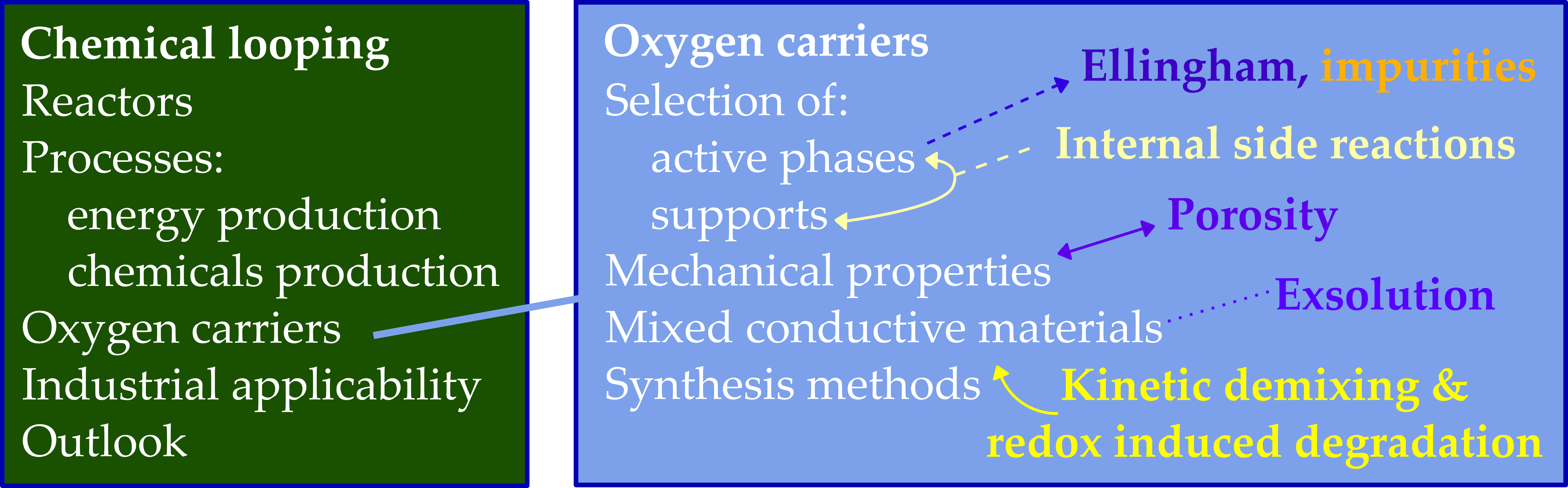
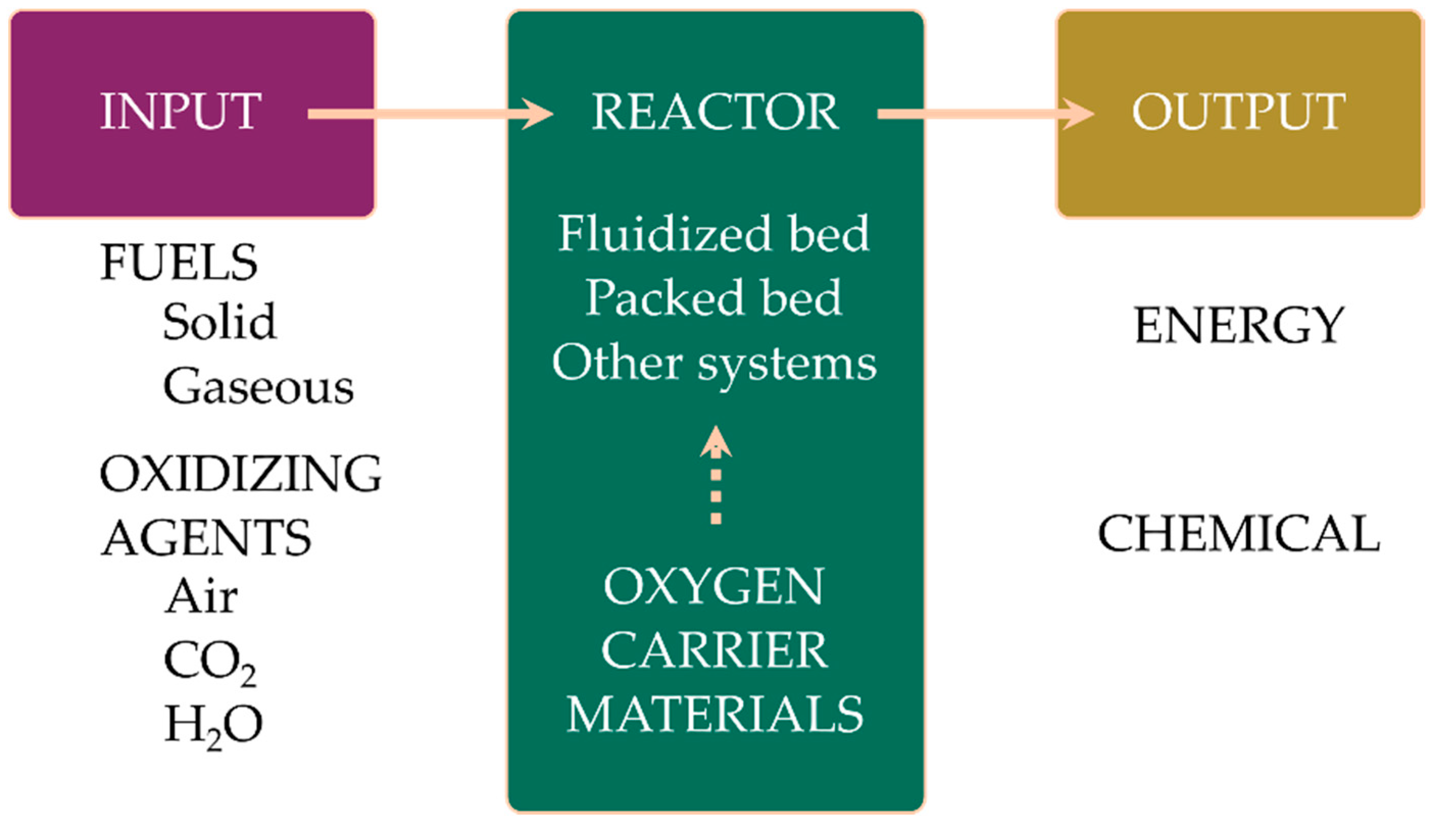
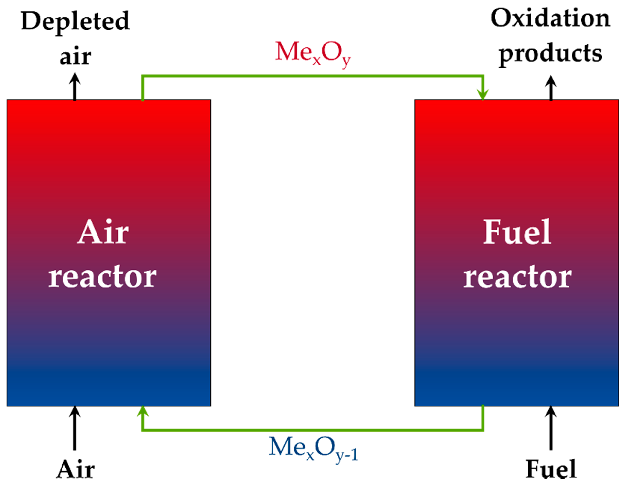
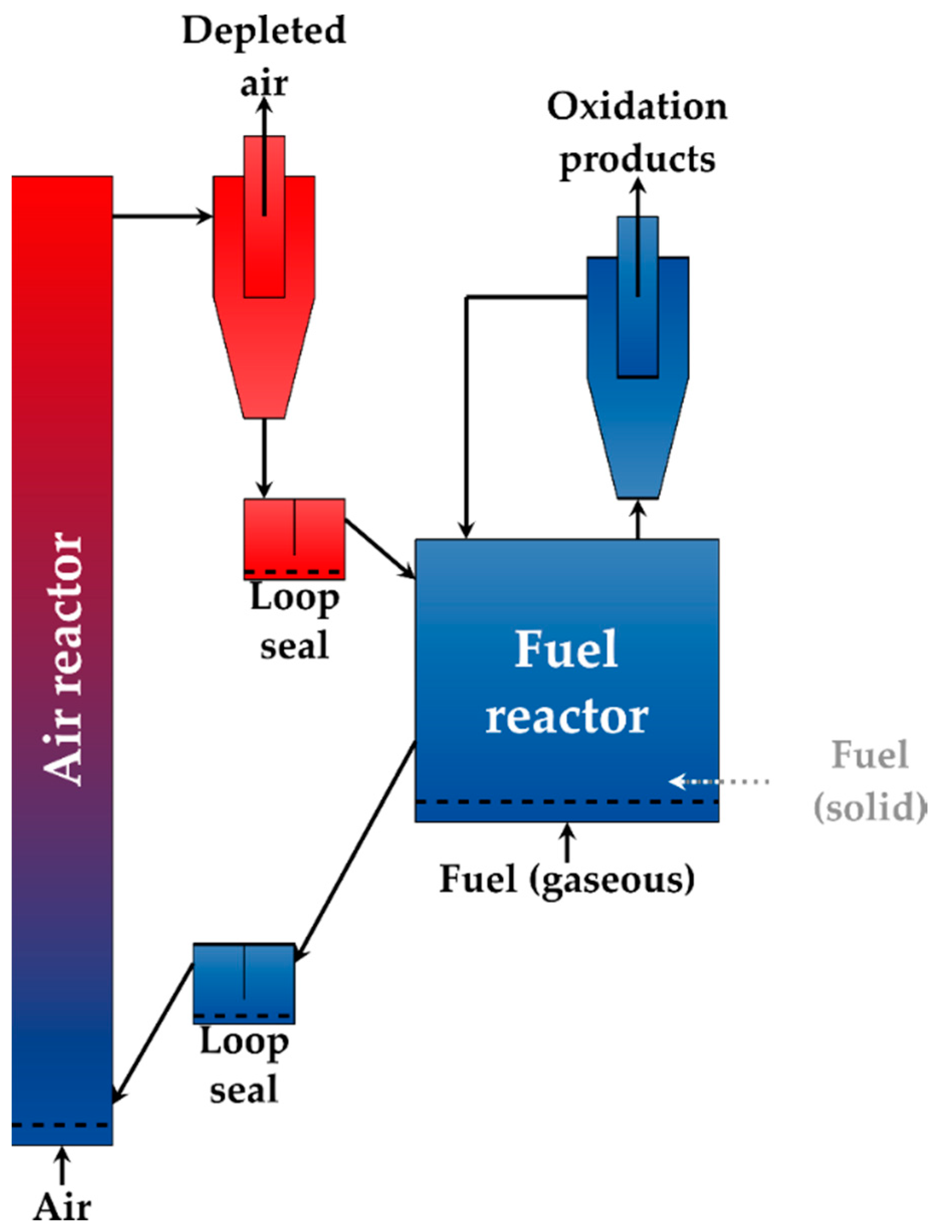
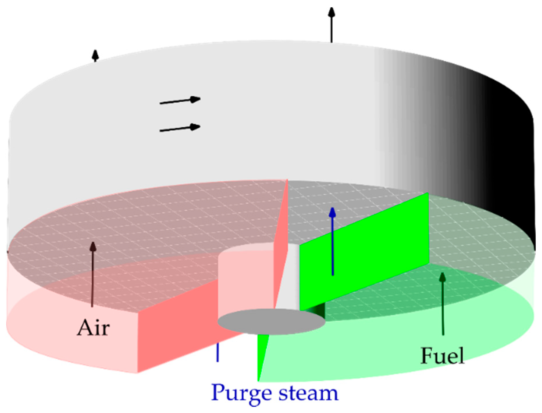
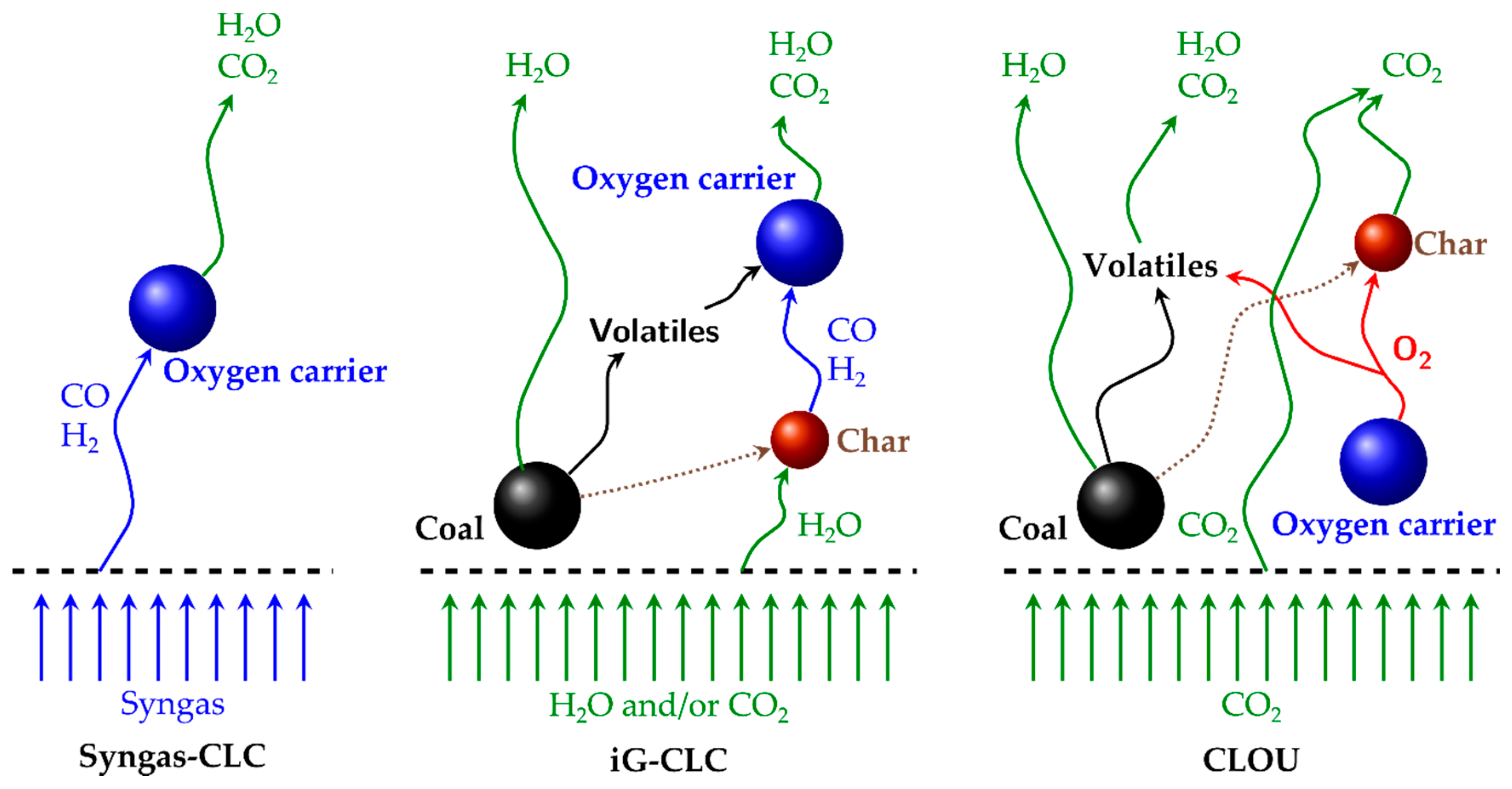
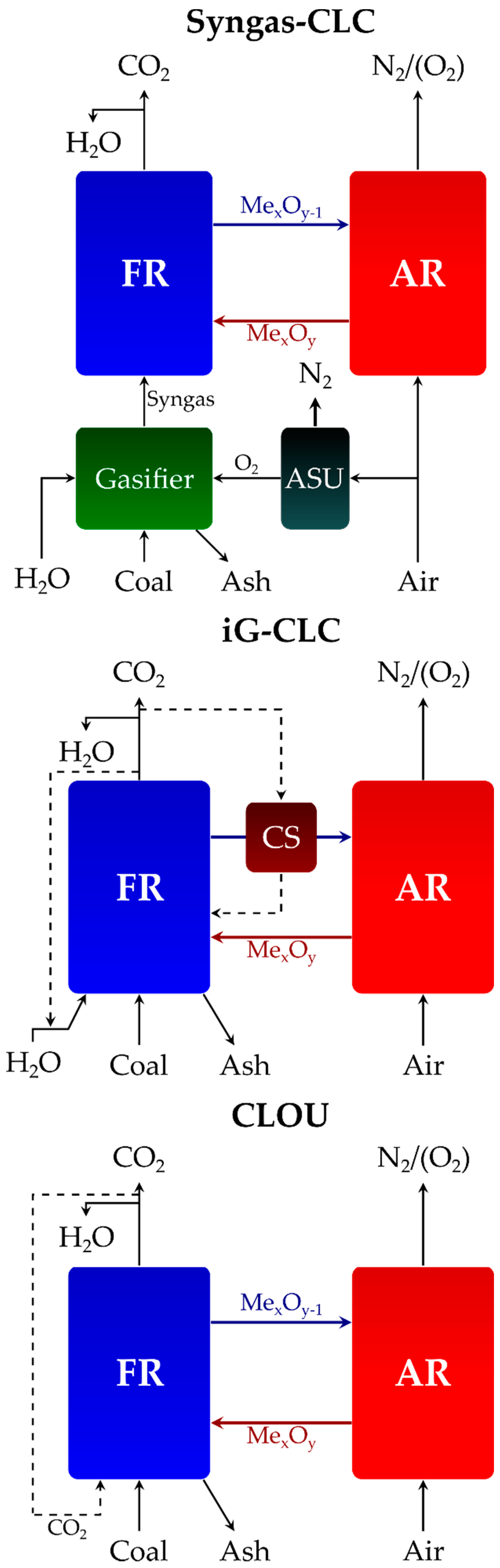
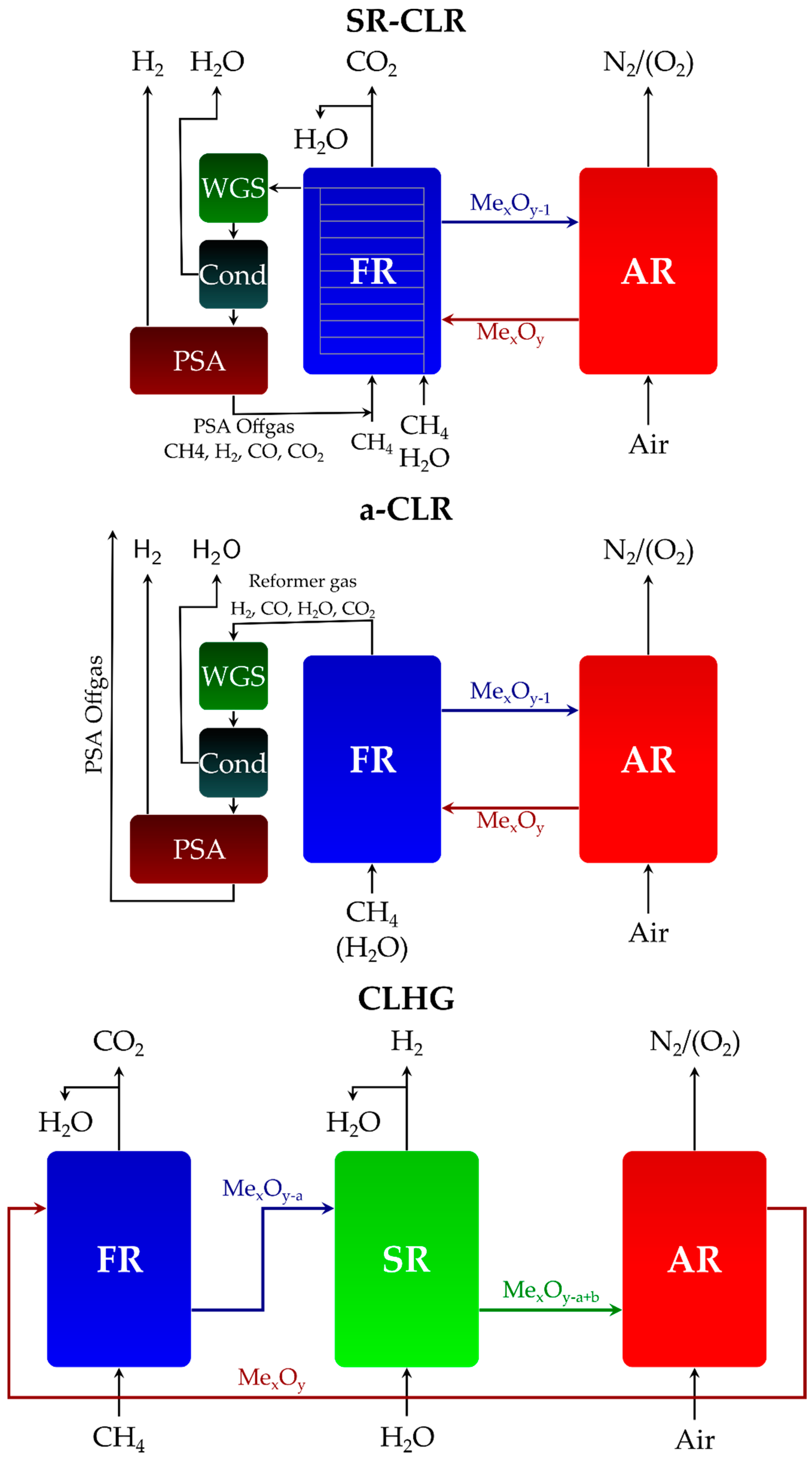
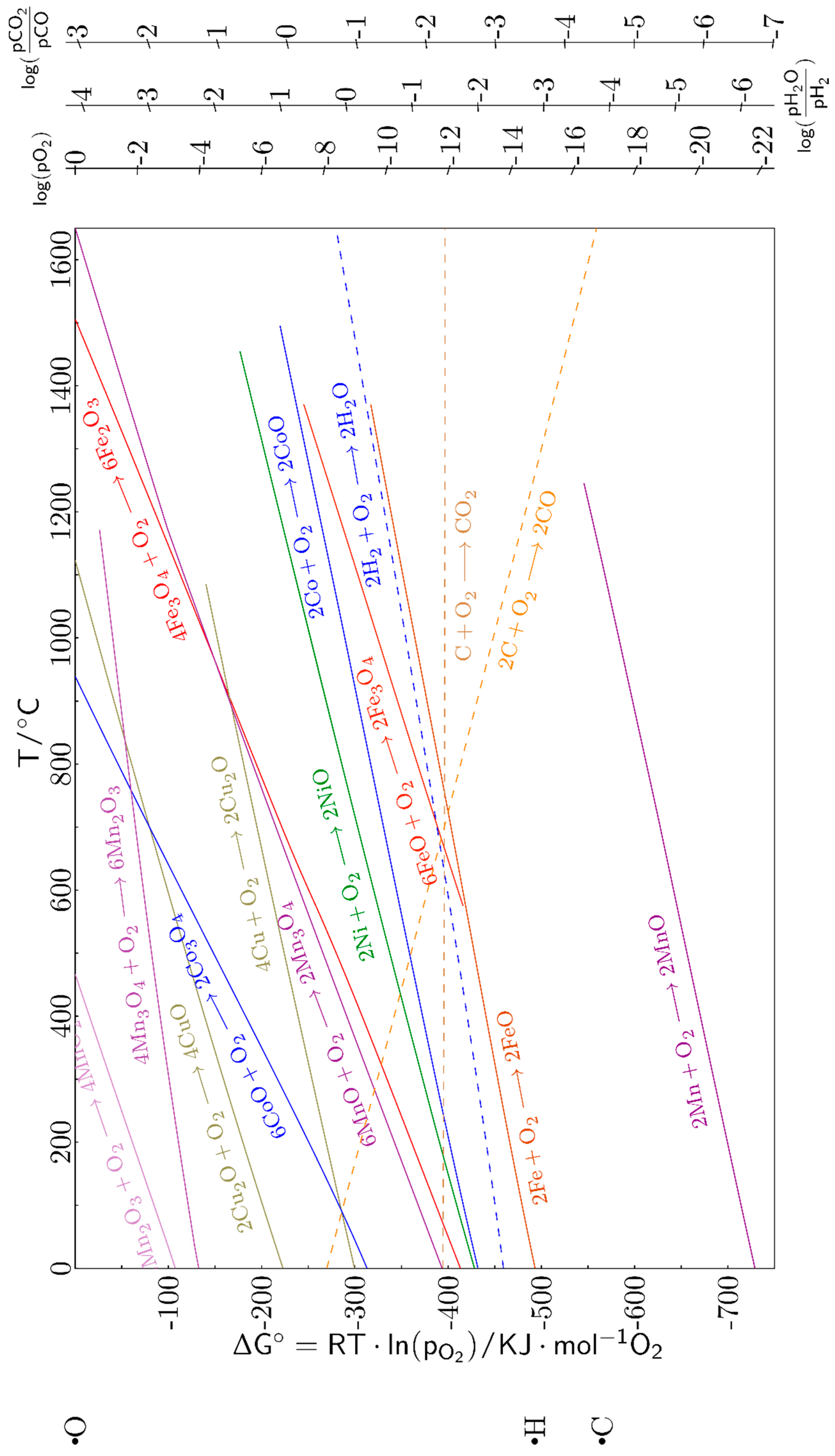
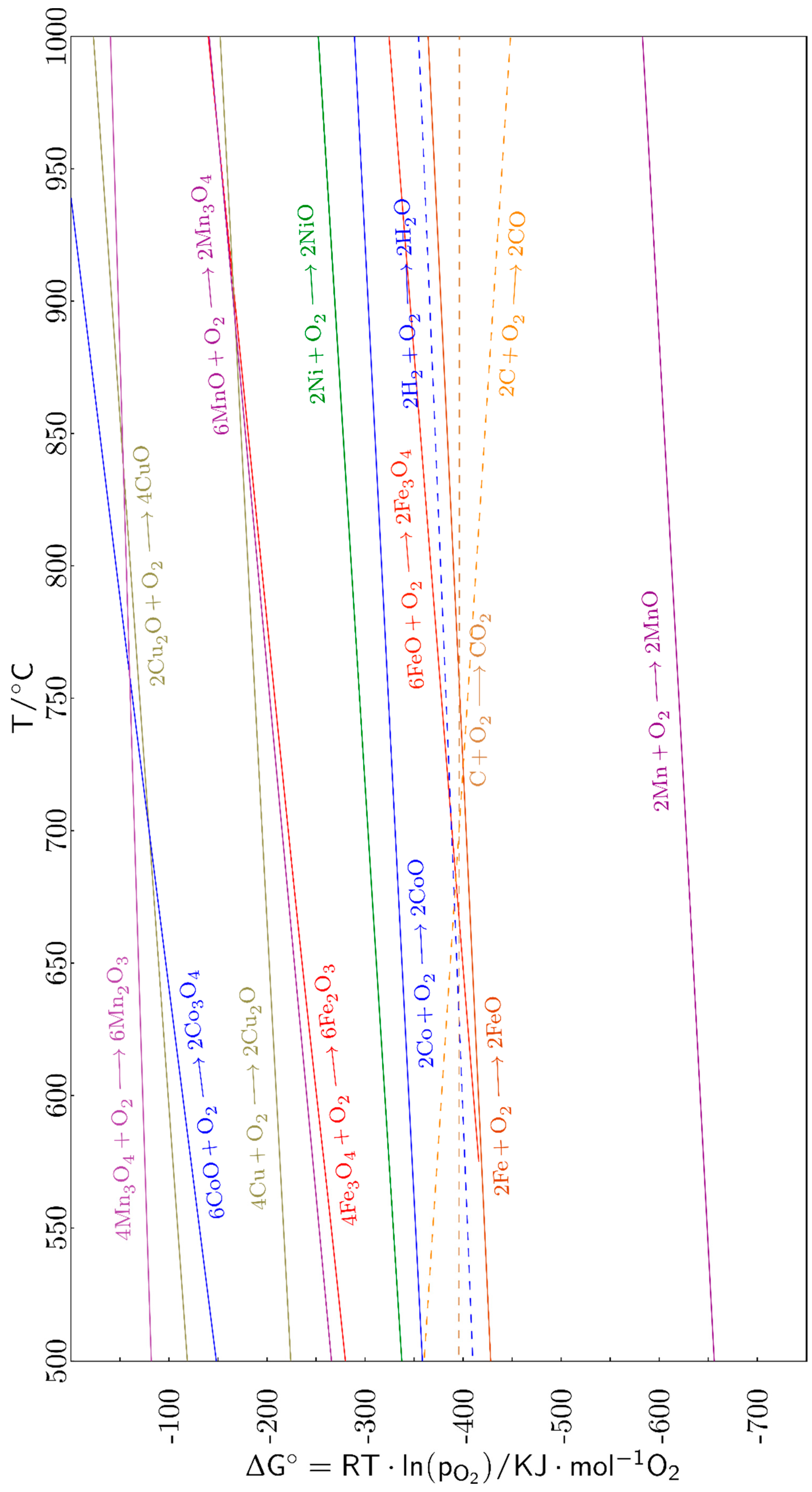
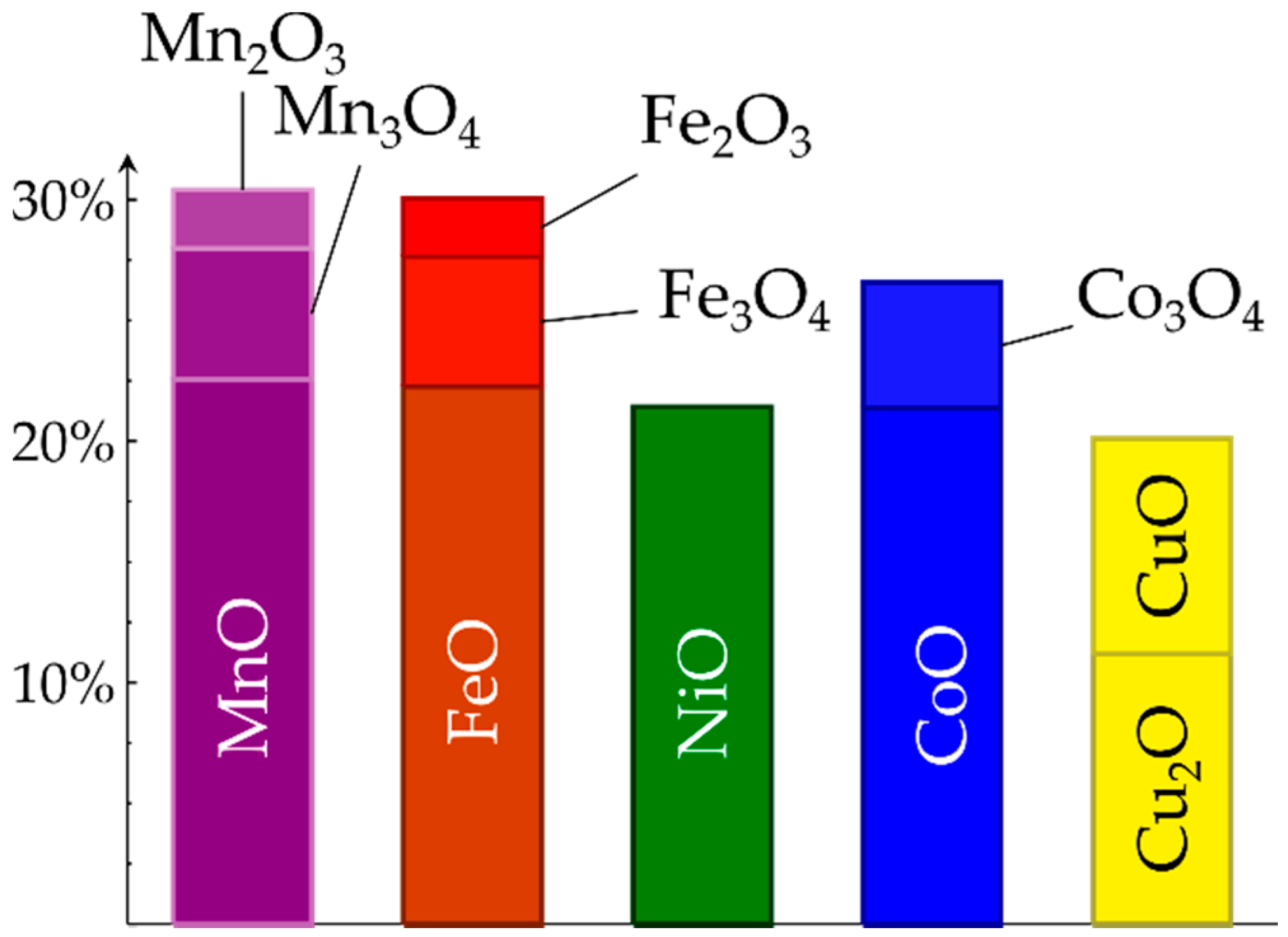
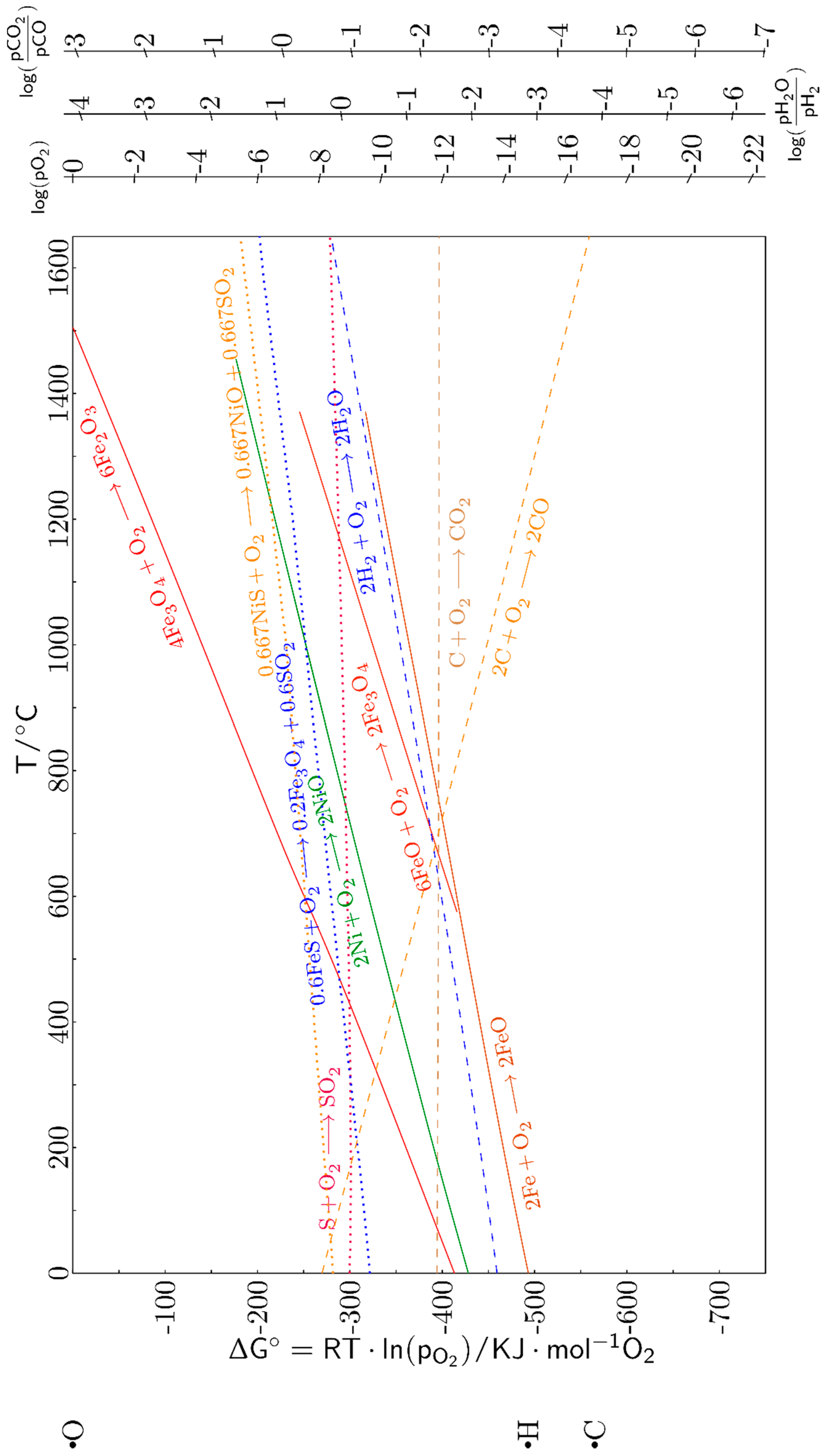
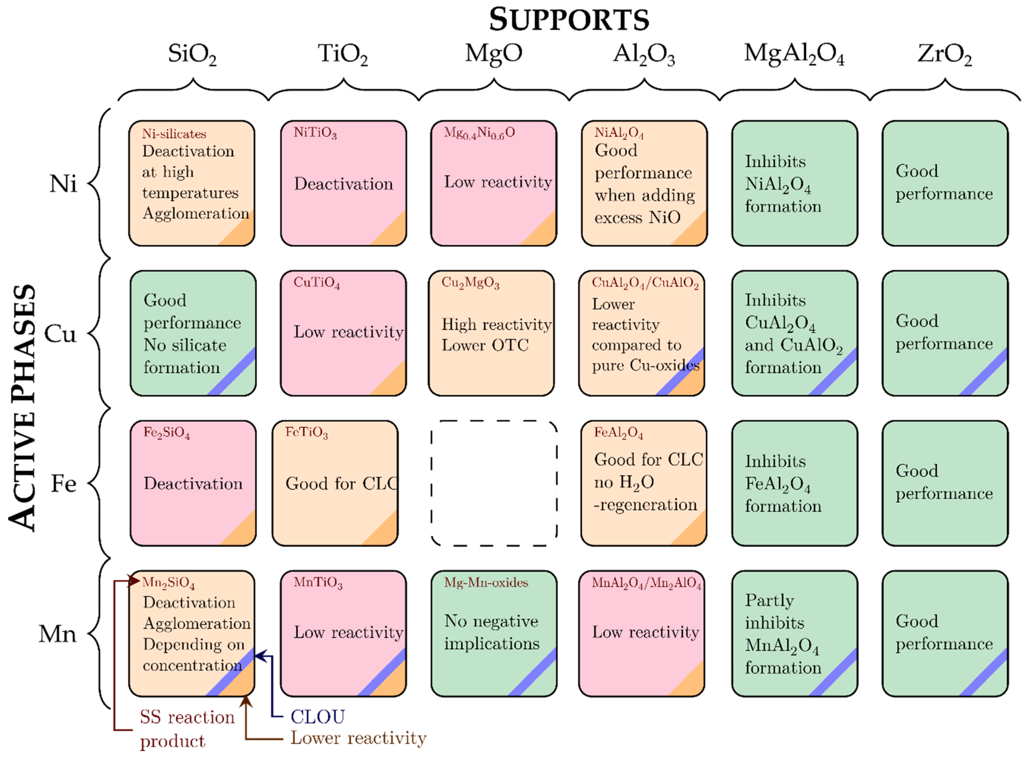
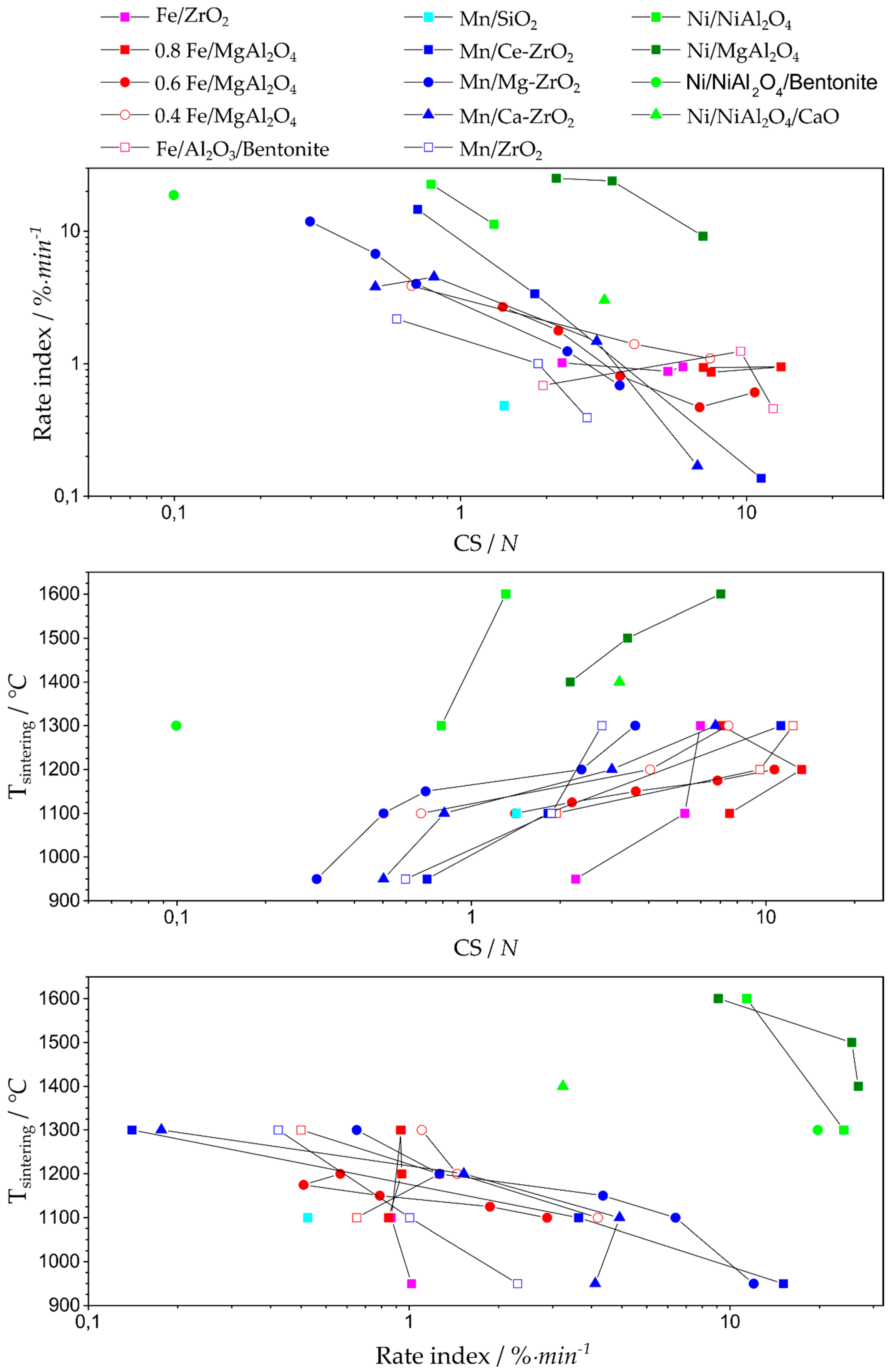
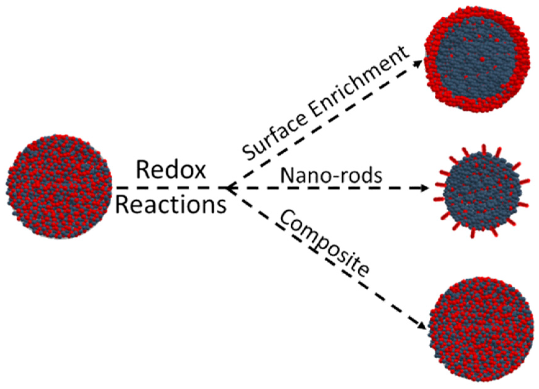
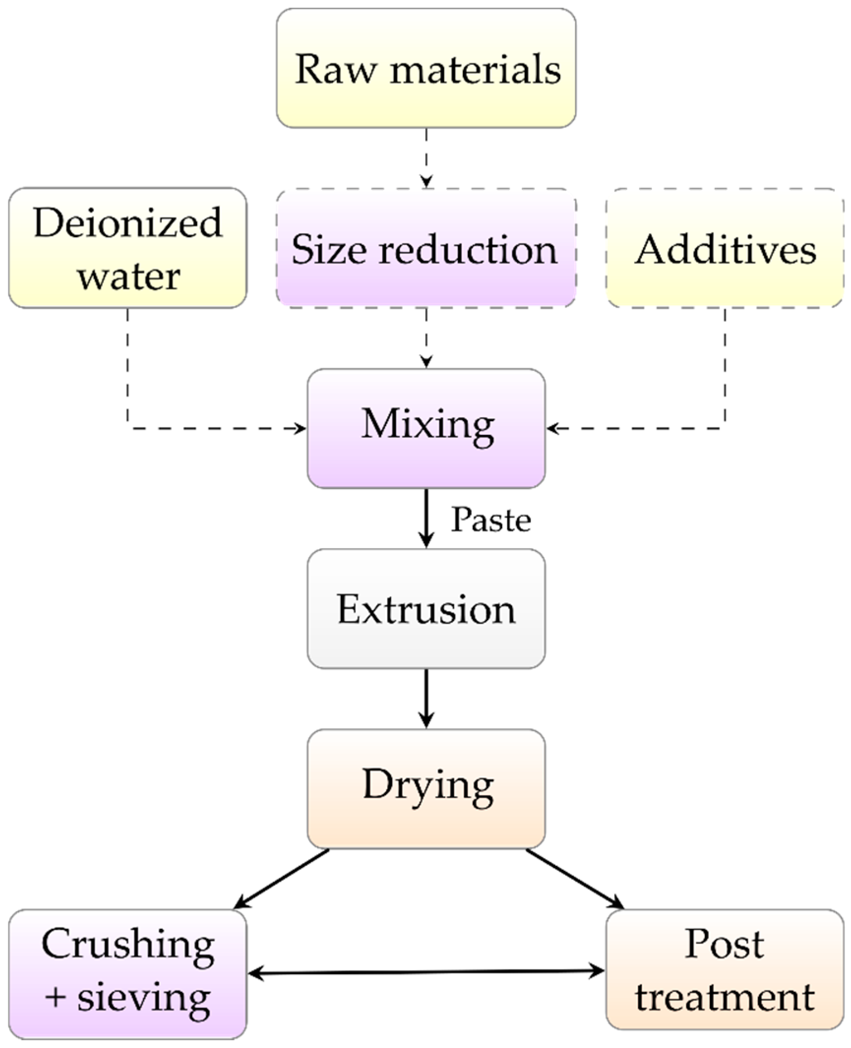
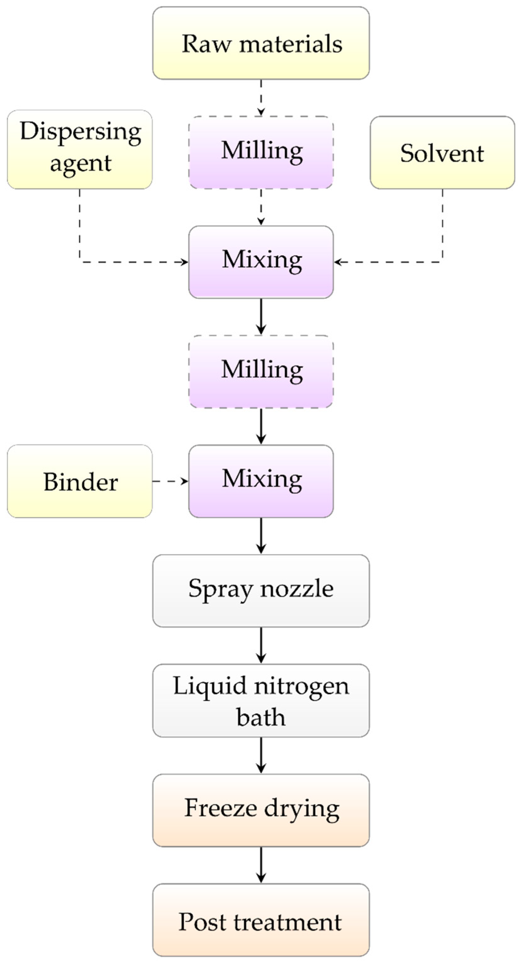
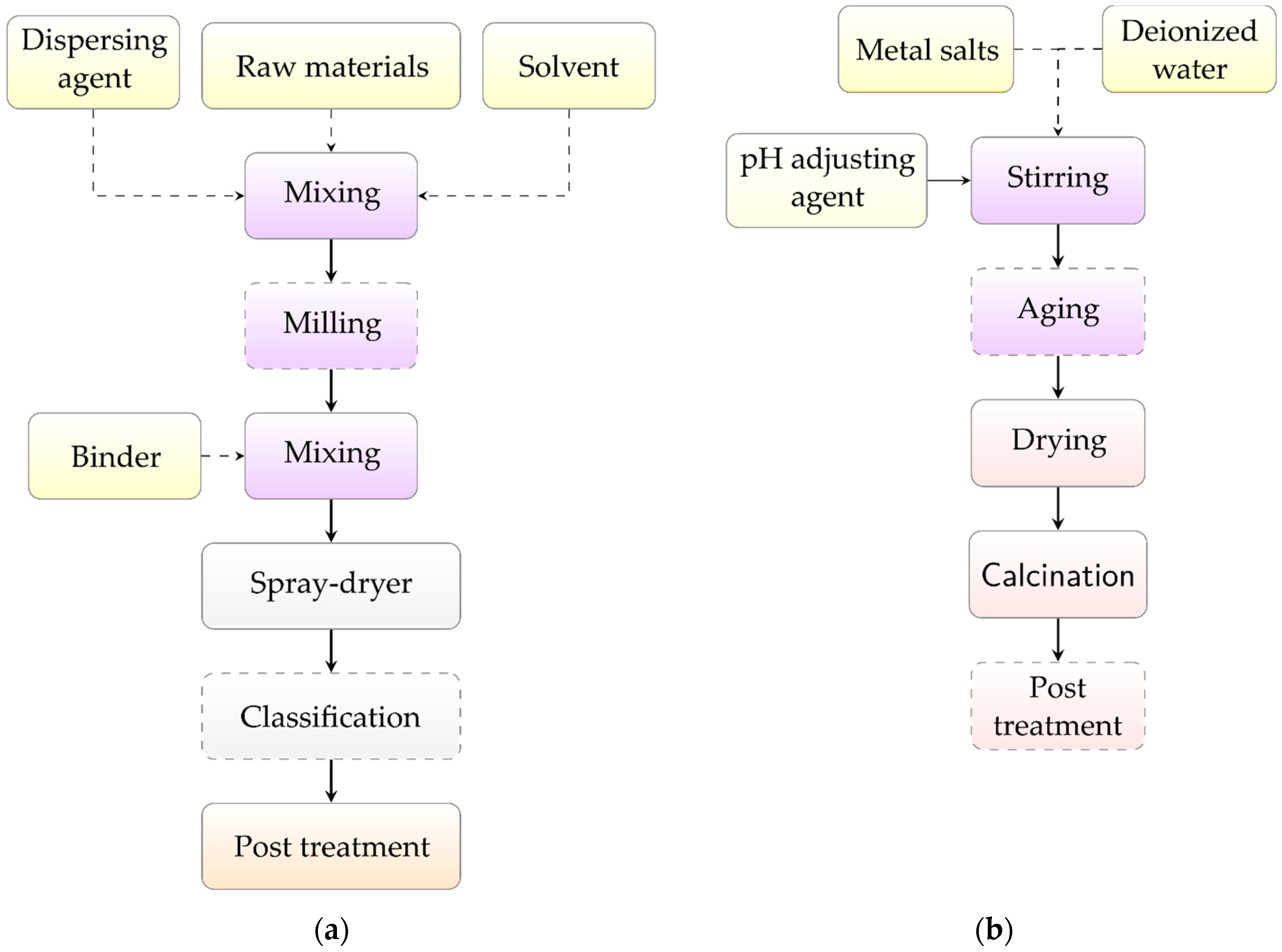
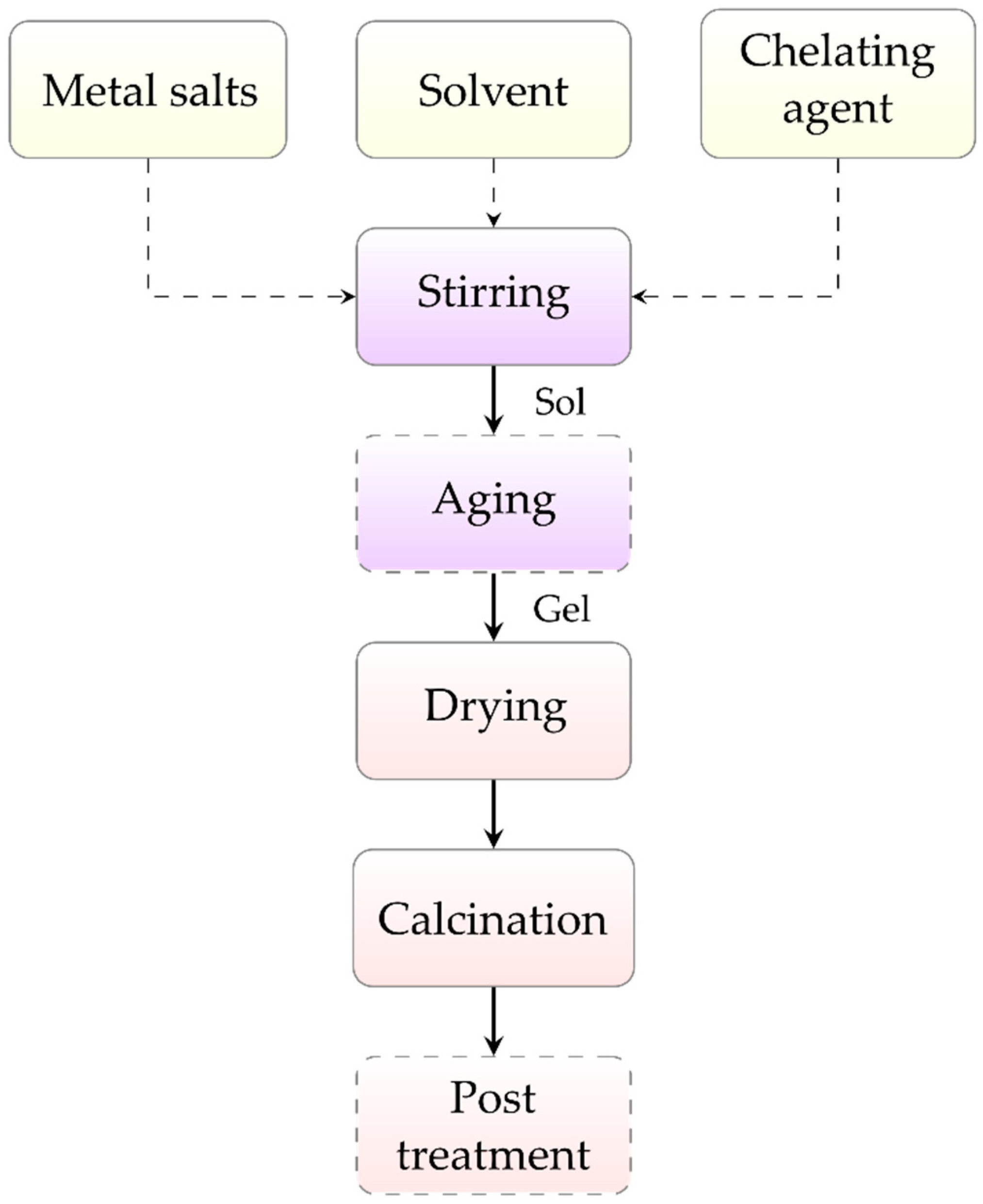
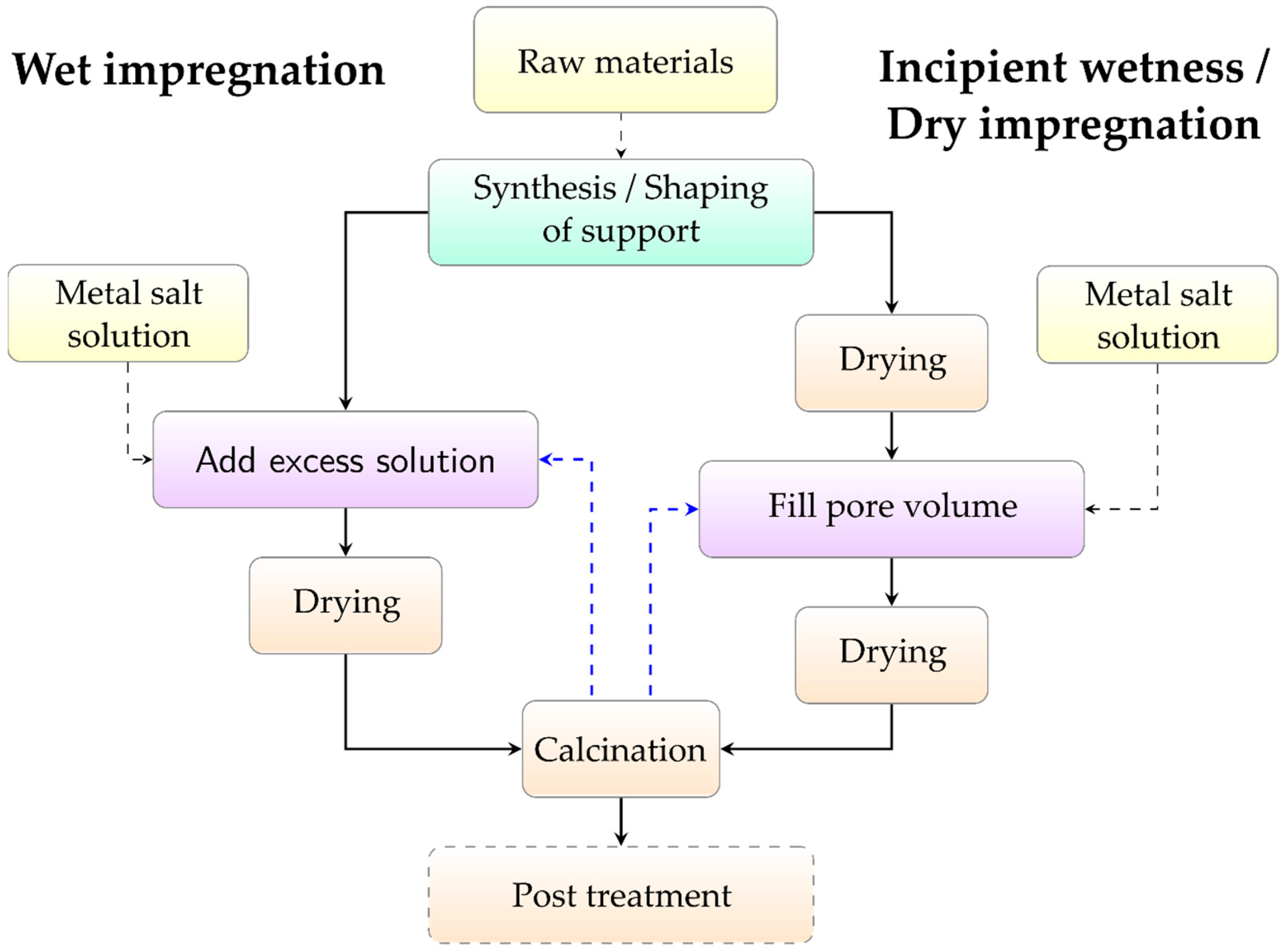
Figure 1. A general overview of the parts of the chemical looping process discussed in this review.
Catalysts 10 00926 g001
Figure 2. General flowsheet of the chemical looping process.
Catalysts 10 00926 g002
Figure 3. Scheme of a conventional circulating fluidized bed chemical looping reactor suitable for chemical looping combustion.
Catalysts 10 00926 g003
Figure 4. Schematic overview of the rotating chemical looping reactor system.
Catalysts 10 00926 g004
Figure 5. Main reaction mechanisms involved in solid-fuel combustion in the three different chemical looping combustion processes, proposed for solid fuels. Reprinted from [20], with permission from Elsevier. CLC: chemical looping combustion, iG-CLC: in situ gasification chemical looping combustion, CLOU: chemical looping with oxygen uncoupling.
Catalysts 10 00926 g005
Figure 6. Chemical looping combustion processes with solid fuels, adapted from [20] and [104]. Acronyms include FR - fuel reactor, AR - air reactor/regenerator, ASU - air separation unit, CS - carbon stripper.
Catalysts 10 00926 g006
Figure 7. Process schemes of steam reforming-chemical looping reforming (SR-CLR), autothermal chemical looping reforming (a-CLR), and chemical looping for hydrogen generation, adapted from [105,107,111]. Acronyms include FR: fuel reactor, AR: air reactor, WGS: water-gas shift reactor, Cond: condenser, PSA: pressure swing adsorption unit, and SR: steam reactor.
Catalysts 10 00926 g007
Figure 8. Ellingham diagram of selected components, calculated by FACTSAGE (1 atm) [142]. Nomographic scales related to H2O/H2 and CO2/CO with their respective origins ‘H’ and ‘C’ are included in the figure.
Catalysts 10 00926 g008
Figure 9. Ellingham diagram of selected components in T-range suitable for chemical looping processes, calculated by FACTSAGE (1 atm) [142].
Catalysts 10 00926 g009
Figure 10. Theoretical oxygen transfer capacity related to several common active materials for chemical looping processes.
Catalysts 10 00926 g010
Figure 11. Ellingham diagram of selected components, calculated by FACTSAGE [142] (1 atm). Dotted lines include reactions with sulfur. Nomographic scales related to H2O/H2 and CO2/CO with their respective origins ‘H’ and ‘C’ are included in the figure.
Catalysts 10 00926 g011
Figure 12. Different active phase/support combinations used for oxygen carriers. Possible solid-state reaction products, decreased reactivity, and presence of CLOU effect are indicated on each tile (see bottom left for explanation). Green and red tiles, respectively, indicate good and bad performance, while orange tiles indicate possible good performance, depending on process conditions and the ratio between active phase and support. Only the most frequently utilized supports are included in the figure. Other supports can be found through the text, and especially in Section 3.5.4.
Catalysts 10 00926 g012
Figure 13. The relation between sintering temperature, crushing strength, and oxygen carrier reactivity of several batches of freeze granulated oxygen carriers synthesized from Mn, Ni, and Fe-based active phases, combined with different supports. The data is collected from Johansson et al. [257].
Catalysts 10 00926 g013
Figure 14. Ionic diffusion-induced structural changes in oxygen carrier particles, reprinted from [34], with permission from Elsevier.
Catalysts 10 00926 g014
Figure 15. A simple flowchart of the mechanical mixing process.
Catalysts 10 00926 g015
Figure 16. A simple flowchart of the freeze granulation process.
Catalysts 10 00926 g016
Figure 17. A simple flowchart of the spray-drying process (a) and of the coprecipitation process (b).
Catalysts 10 00926 g017
Figure 18. A simple flowchart of the sol-gel process.
Catalysts 10 00926 g018
Figure 19. A simple flowchart of the impregnation processes.
Catalysts 10 00926 g019
Table 1. Select fluidized bed chemical looping process development and pilot plants across the world, adapted from [17].
InstitutionLocationYearCapacity (kWth)Ref
Vienna University of TechnologyVienna, Austria2009120[43]
Hamburg University of TechnologyHamburg, Germany201225[44]
Chalmers University of TechnologyGothenburg, Sweden2012100[45]
Darmstadt University of TechnologyDarmstadt, Germany20121000[46]
Southeast UniversityNanjing, China201250[47]
University of UtahSalt Lake City, USA2012200[17]
National Energy Technology LaboratoryMorgantown, USA201350[48]
Instituto de Carboquímica (ICB-CSIC)Zaragoza, Spain201450[49]
Huazhong University of Sci. and Tech.Wuhan, China201650[50]
VTT Technical Research CenterEspoo, Finland201650[51]
Japan Coal Energy CenterTokyo, Japan2017100[52]
Korean Institute of Energy ResearchDaejeon, Korea2018500[53]
Table 2. An overview of some of the different chemical looping technologies found in the literature.
FocusPrimary FuelProcessReactor Type
CombustionGasCLCChemical Looping Combustionf 1, m 2, p 3
-SolidSyngas-CLCSyngas-Chemical Looping Combustionf, m, p
-SolidiG-CLCIn situ Gasification Chemical Looping Combustionf, m
-SolidCLOUChemical Looping with Oxygen Uncouplingf
-GasGSCGas Switching Combustionf
ChemicalsGasSR-CLRSteam Reforming-Chemical Looping Reformingf
-Gas, liquida-CLRAutothermal-Chemical Looping Reformingf
-GasGSRGas Switching Reformingf
-GasCSRChemical Switching Reformingf
-Gas, liquidSE-CLSRSorption Enhanced-Chemical Looping Steam Reformingf, m, p
-GasCLHG/TRCH/OSDChemical Looping for Hydrogen Generation/Three Reactor Chemical Looping/One Step Decarbonizationf, m, p
-SolidSCLSyngas Chemical Loopingm
-SolidCDCLCoal Direct Chemical Loopingf, m
Oxygen Production/CLASChemical Looping Air Separationf, m, p
1 f: fluidized bed, 2 m: moving bed and 3 p: packed bed.
Table 3. Advantages and disadvantages of several investigated reactor concepts related to chemical looping.
ADVANTAGESDISADVANTAGES
INTERCONNECTED FBFlexible and continuous operation Intraparticle diffusion resistance can reduce performance during continuous operation
Mature technology, easy to scale Oxygen carrier attrition
Stable production of reaction products Fluidization problems by agglomeration
Particle mixing reduces the risk for hot-spots Stable solid circulation at higher pressures is more challenging
High mass transfer rates Fines separation at higher pressures is challenging
Viable for solid, liquid, and gaseous fuels
PACKED BEDEase of working under pressurized conditionsThe risk for hot-spots when reactions are heavily exothermal
Inherent separation of gas and particlesNeed for using a sophisticated gas switching system
Negligible particle degradationPossible deterioration due to particle volume changes
More compact reactors, leading to reduced capital costDifferent reactions can occur when reaction front proceeds through the bed
Batch operation
Not for solid fuels
ROTATING REACTORContinuous operationComplex operation, difficult to scale
Ease of working under pressurized conditionsReactor geometry depends on oxygen carrier and desired products
Negligible particle degradationHigh purge steam requirements lead to lower net efficiency
More compact reactors, leading to reduced capital costOnly for gaseous fuels
No need for sophisticated gas switching systemsPossible deterioration due to particle volume changes
The risk for hot-spots when reactions are heavily exothermal
Table 4. Selection of perovskite and fluorite materials used in chemical looping, their synthesis procedure, and key points related to their stability and performance. Core-shell particles are indicated by core@shell.
MaterialSynthesisSupport forKey Points Related to Stability and PerformanceRef
La0.5Sr0.5Co0.5Fe0.5O3g.n. 1/s.d. 2 + f.g. 3PureNo indication of decomposition after tests, suitable for CLC.[280]
La0.6Sr0.4Co0.2Fe0.8O3−δc. 4PureThe formation of La2CoO4 and sintering is observed. Steady hydrogen production.[268]
LaFeO3−δg.n./s.d. + f.g.PureCarbon formation at the end of the first reduction cycle. Earlier carbon formation in the following cycles.[280]
La0.8Sr0.2FeO3−δg.n./s.d. + f.g.PureInteresting for CLR, high selectivity for syngas generation. Carbon formation at the end of the first reduction cycle.[280]
La0.5Sr0.5FeO3−δg.n./s.d. + f.g.PureInteresting for CLR, high selectivity for syngas generation. No carbon formation during earlier reduction cycles. Increased Sr content decreases both selectivity towards H2 and reactivity with methane.[280]
La0.7Sr0.3FeO3−δc.PureNo indication of structural changes during operation, no sintering is observed for 100 cycles. Steady hydrogen production.[268]
La0.8Sr0.2FeO3−δs.s. 560 wt% Fe2O3Improved reactivity compared to TiO2, Al2O3, and YSZ-supported references. Also reactive at lower temperatures. Good resistance towards C-formation.[250]
La0.7Sr0.3FeO3−δs.s.PureUnstable under redox environment (reducing conditions).[158]
La0.7Sr0.3FeO3−δs.s.50 wt% Fe2O3Better activity than CTF, more oxygen exchange, but less stable.[158]
La0.8Sr0.2FeO3−δs.g. 650 mol% Fe2O3@LSFExcellent reactivity and syngas selectivity. Fe-exsolution from LSF shell, reactivity controlled by O2- diffusion.[270]
La0.8Sr0.2FeO3−δs.g.50 mol% Fe2O3Increased C deposition compared to the core-shell particle. A-site enrichment at the surface might lead to a core-shell particle after enough cycles.[270]
La0.8Sr0.2FeO3−δs.s.60 wt% Fe2O3Good performance compared to OCs with inert supports.[272]
La0.8Sr0.2FeO3−δs.g.50 wt% Fe2O3@LSFThe OC with nanoparticle cores is found to be 10–100 times more reactive for methane partial oxidation compared to the inert supported OCs. It also displays better reactivity, product selectivity, and resistance to C formation compared to composite.[272]
La0.8Sr0.2FeO3−δs.g.50 mol% Co3O4@LSFExsolution of Co occurs with C deposition. Syngas selectivity is worse than Fe2O3-core.[281]
La0.8Sr0.2FeO3−δs.g.50 mol% Fe2O3@LSFBetter syngas yield vs. LFO, SFO, and La0.5Sr0.5FeO3−δ.[281]
La0.8Sr0.2FeO3−δs.g.50 mol% Mn2O3@LSFMn–Fe-spinel is formed, resulting in reduced OTC, good syngas selectivity, but low yields.[281]
La0.7Sr0.3FeO3−δs.g.50 mol% Fe2O3@LSFBetter syngas yield vs. LFO, SFO, and La0.5Sr0.5FeO3−δ, deemed suitable for CLR.[281]
La0.5Sr0.5FeO3−δs.g.50 mol% Fe2O3@LSFSrFe12O19 formation.[281]
SrFeO3s.g.50 mol% Fe2O3@SFStable in reducing environment, but poor performance due to complete avoidance of exsolution of Fe, SrFe12O19 formation.[281]
LaFeO3s.g.50 mol% Fe2O3@LFExtreme cokes formation during reduction due to extreme exsolution of Fe.[281]
La0.8Sr0.2FeO3−δn.i. 760–75 wt% Fe2O3Good steam conversion due to reoxidation of exsolved Fe and reconstruction of decomposed LSF.[282]
La0.8Sr0.2FeO3−δs.s.40 wt% Fe2O3Fractured into powder due to the redox environment.[283]
La0.9Sr0.1AlO3−δs.s. + i. 835 wt% NiONi-exsolution occurs (most likely).[284]
LaCo0.83Fe0.1O3r.g. 9pureDecomposition occurs as Co3O4 is detected after oxidation.[285]
La0.81Ce0.09Co0.82Fe0.16O3r.g.pureDecomposition occurs as Co3O4 is detected after oxidation. Adding Ce does not improve reactivity.[285]
LaMn0.73Fe0.38O3r.g.pureDecomposition occurs as Mn3O4 is detected after oxidation.[285]
LaMnO3n.c. 10pureDecomposition occurs as Mn3O4 is detected after oxidation.[285]
CaxSr1−xTiyNi1−yO3−δs.g.30 mol% Fe2O3High initial activity. Slight deactivation due to the exchange of Ni in the lattice for Fe. Complete substitution results in stable redox activity.[159]
Ce0.9Gd0.1O2−δs.s.35 wt% NiONi-sintering occurs.[284]
Ce0.8Gd0.2O2−δm.m. 1130 wt% Fe2O3The reduction rate of iron oxide is clearly increased compared to ZrO2 and CeO2 supports.[184]
Ce0.9Gd0.1O2−δs.s.40 wt% Fe2O3Formation of FeCeO3 and segregation of Fe from surface (exsolution).[283]
Ce1−xFexO2−δc.p. 12x = 0, 0.1, 0.2, 0.3, 0.4, 0.5, 1The methane activation rate is dominated by surface iron dispersion, while the CO formation rate is related to oxygen mobility. During reduction, metallic Fe and CeFeO3 are formed, with the latter resulting in CeO2 and Fe during further reduction. Ion migration is observed, with Fe migrating towards the interior of the material.[164]
CeO2c.p.Fe2O3, ratio Ce:Fe 7:3High syngas selectivity due to dispersed Fe2O3 and Ce–Fe solid solution interaction. Reduced oxygen carriers could be reoxidized by air and restored in its initial state. Increased solid-solution of Fe in fluorite lattice after many redox cycles.[276]
CeO2s.s., c.p.30 & 40 mol% Fe2O3High initial activity but notably deactivates with an increasing number of cycles. The inability of Fe to stabilize inside CeO2 support leads to largely segregated iron oxide on the surface, causing decreased accessibility of O2- to gaseous fuels.[159]
CeO2m.m.30 wt% Fe2O3Lower reduction rate than GDC-supported material. Increased H2-reduction rate when FeO transforms to Fe (better electronic conductivity of CeO2 in its fully reduced state).[184]
CeO2p. 13 + w.i. 14Ni (2.1 wt%, 8–11 wt% and 38.5 wt%)Metallic Ni acts as a methane activator during dry reforming and remains in the metallic state due to the presence of CO2 under working conditions. Selectivity is practically complete towards syngas when oxidized by CO2. Indications of promotion of oxygen mobility from the support to active Ni-particles in the intermediate loading. Indications of differences in surface concentrations of all elements during operation.[286]
CaTi0.125Mn0.875O3s.p.15/f.g.PureExcellent results for CLOU. Ti incorporation in perovskite prevents coke formation.[287]
CaTi(1-x)FexO3−δs.s.36 wt% Fe2O3Significant improvements in Fe2O3 reduction rate and lattice oxygen utilization using CTFO, likely induced by rapid ion transport at the interface between Fe2O3 and CTFO.[288]
CaTi0.85Fe0.15O3−δs.s., s.g.Pure, 50wt% Fe2O3Limited oxygen transfer capacity, better combining with transition metal as an active phase. More stable in comparison with LSF when together with the Fe-active phase.[158]
CaTixFe1−xO3−δi.surface modification of ilmeniteCalcination temperature influences the formation and location of CTFO in the ilmenite, resulting in different properties. Fe-exsolution in pure ilmenite shortens the lifetime in the OC material. In CTFO, Fe mobility is lower, leading to increased lifetimes.[278]
1 g.n.: glycine-nitrate synthesis, 2 s.d.: spray-drying, 3 f.g.: freeze granulation, 4 c.: commercial powder, 5 s.s.: solid-state synthesis, 6 s.g.: sol-gel synthesis, 7 n.i.: not available, 8 i.: impregnation, 9 r.g.: reactive grinding, 10 n.c.: nanocasting, 11 m.m.: mechanical mixing, 12 c.p.: coprecipitation, 13 p.: precipitation, 14 w.i.: wet impregnation and 15 s.p.: spray-pyrolysis.

