Article

An Eco-Friendly Fluidizable FexOy/CaO-γ-Al2O3 Catalyst for Tar Cracking during Biomass Gasification

1
Department of Chemical Engineering, University of Costa Rica, San Jose 11501, Costa Rica
2
Electrochemistry and Chemical Energy Research Center, University of Costa Rica; San Jose 11501, Costa Rica
3
Chemical Reactor Engineering Center, Faculty of Engineering, Western University, London, ON N6A5B9, Canada
*
Author to whom correspondence should be addressed.
Catalysts 2020, 10(7), 806; https://doi.org/10.3390/catal10070806
Submission received: 27 May 2020 / Revised: 28 June 2020 / Accepted: 13 July 2020 / Published: 20 July 2020
(This article belongs to the Special Issue Commemorative Issue in Honor of Professor Hugo de Lasa)

Abstract

:
The present study deals with the development, characterization, and performance evaluation of an eco-friendly catalyst, using 2-methoxy-4-methylphenol (2M4MP) as a surrogate tar. The 2M4MP was selected due to its chemical functionalities and the fact that it is a good model compound to represent the tar formed during biomass low temperature gasification. The eco-friendly catalyst was prepared using the typical Fe and Ca minerals which are present in ash. These ash components were added to a fluidizable γ-Al2O3 support using a multistep incipient impregnation, yielding Fe oxides as an active phase and CaO as the promoter. The prepared catalyst displayed a 120 m2/g BET specific surface area, with few γ-Al2O3 bulk phase changes, as observed with XRD. TPD-NH3 and pyridine FTIR allowed us to show the significant influence of CaO reduced support acidity. A TPR analysis provided evidence of catalyst stability during consecutive reduction–oxidation cycles. Furthermore, catalyst evaluation vis-à-vis catalytic steam 2M4MP gasification was performed using the fluidized CREC riser simulator. The obtained results confirm the high performance of the developed catalyst, with 2M4MP conversion being close to 100% and with selectivities of up to 98.6% for C1-C2 carbon-containing species, at 500 °C, with a 7.5 s reaction time and 1.5 g steam/g 2M4MP. These high tar conversions are promising efficiency indicators for alumina catalysts doped with Fe and Ca. In addition, the used catalyst particles could be blended with biochar to provide an integrated solid supplement that could return valuable mineral supplements to the soil.

Graphical Abstract

1. Introduction

Biomass steam gasification is a key process for renewable waste resource conversion, as is the case for Costa Rican coffee pulp [1]. Coffee pulp is a solid, environmentally harmful residue from coffee production. However, coffee pulp gasification can be negatively affected by tar formation [2].
Tar is a by-product of biomass gasification, consisting of a range of hydrocarbon species, mainly aromatics, and complex aromatic polycyclic hydrocarbons. Tar is composed of over a hundred compounds, with this being a function of the biomass type, the particle size, the gasification device, the thermal treatment, the gasification agent, and the gasification pressure and temperature [3,4,5,6,7]. Tar constituents can be classified either by their number of rings [8,9] or as primary, secondary, and tertiary [10]. These chemical species usually contain oxygenates (phenolic ethers), alkylphenols, heterocyclic ethers, and other polyaromatic hydrocarbons (PAHs). One of the simplest definitions of tar includes all the organic compounds that result from biomass steam gasification, with a molecular weight larger than benzene [11,12]. It is anticipated, in this respect, that research addressing tar formation mechanisms and catalyst activity can lead to an improved gasification process [13,14].
Thus, a catalytic process following coffee pulp gasification, which converts formed tars into valuable products, can be of great interest and provide the best approach to Costa Rican coffee pulp gasification. The effective tar conversion following the coffee pulp gasification can also contribute to decreased operational costs and improved financial returns [12,15,16,17,18].
Ash is an important component of Costa Rican coffee pulp, frequently as high as 10 wt%. Key components of Costa Rican coffee pulp’s ash are iron and calcium. Iron and calcium can have a beneficial effect by catalyzing tar cracking and conversion. [19,20,21,22,23,24]. Boström et al. [25] provided a model accounting for primary and secondary reactions, which are affected by the concentrations of ash-forming elements. Wang at al [26] reported that ash has the significant negative effect of depressing biomass melting and sintering temperatures. Furthermore, ash represents a barrier to biomass gasification since it has poor fluidization properties and displays small inner specific surface areas. It should be mentioned that fluidization properties and inner specific surface area are two important attributes of industrial fluidizable catalysts [27].
Chen et al. [28], as well as other investigators [9,29,30,31,32,33], noted that tar conversion can be improved using alkaline and alkaline-earth oxides such as CaO or MgO. Experimental results derived from this research showed that it is crucial to control both the oxygen and CaO content in biomass gasification. This is essential to achieve the synergetic effects related to biotar cracking and, ultimately, to produce a syngas with the desired composition [30,34,35].
Iron, which is one of the active components in olivine [24,36,37,38,39], has been identified as a suitable catalyst component for both biomass gasification and tar conversion. However, technical issues are still pending regarding the reactivity and desirable iron loading. In this respect, some of the work of other authors considers that metallic iron is the active phase and that the oxides can lead to catalyst deactivation [40]. However, other studies show that successful tar treatment processes involve iron oxides [37]. Thus, there is still a lack of conclusive evidence about the desirable iron chemical state [41].
Concerning tar conversion, Adnan et al. [42] investigated a Fe2O3/SiO2-Al2O3 catalyst with high toluene conversions at 25 s and 600 °C. Experiments also showed that higher iron oxides increase the number of acid sites on the SiO2-Al2O3 surface. Furthermore, Zamboni [37] considered Fe-Ca interactions in a Fe-based/CaO catalyst/sorbent for CO2 sorption and hydrogen production. These authors studied toluene catalytic activity in a fixed bed reactor and TGA analysis for CO2 capture during gasification. Similar studies were carried out by others [43], assessing catalytic activity and the best catalyst loading ratios, in fixed bed reactors. Furthermore, Xu et al. [29] considered biomass gasification using an unsupported low specific surface area Fe/CaO catalyst, establishing the effect of Fe/CaO on the H2 and syngas yields.
On this basis, one can conclude that no study in the technical literature involves a fluidizable and reproducible eco-friendly catalyst based on FexOy/CaO on a γ-Al2O3 support for tar biomass-derived conversion. This catalyst is rigorously evaluated in the present study, using 2M4MP as a tar surrogate. The developed catalyst shows properties that make it an excellent candidate for biomass gasification with tar conversion. One can thus envision a successfully integrated coffee pulp gasification process in Costa Rica that takes advantage of ash components, maximizing tar conversion and, as a result, minimizing costly downstream tar disposal.

2. Results and Discussion

2.1. Constraints in Catalyst Design

Important considerations are required for the design and the development of an eco-friendly catalyst emulating ash in biomass gasification [44]. To study the chemical composition of the ash available in a downdraft gasifier operated in Costa Rica, different ash samples were analyzed, and these are reported in Table S1 in the Supplementary Materials. The main identified potentially active components were calcium, iron, and potassium.
In this respect, it is important to note that some identified ash components, such as potassium, should be avoided in the eco-friendly catalyst formulation. For instance, while potassium was reported as a promoter [45,46,47,48], potassium species have the potential to agglomerate the catalyst [49,50]. Catalyst agglomeration is a function of potassium loading and gasification temperature. Texeira, in 2012, also identified among other detrimental species, K2S2O3, K2SO4, and KCl. Sulfates are formed via sulfation reactions, favored by chlorine, yielding K2SO4 and condensed KCl [51]. Furthermore, K3PO4 was also found in gasifiers [52], together with other inorganics such as SiO2 and other glass forming species [26,53,54].
Thus, to be able to design a successful, eco-friendly, fluidizable catalyst for biomass-derived tar conversion, one must first consider that issues with various potassium species can be avoided if one omits them from the catalyst formulation, as is considered in the present study.

2.2. Design of the Proposed Catalyst

Given the constraints described in Section 2.1, the following factors were considered while selecting the catalyst’s key components: a) having a γ-Al2O3 support with an adequate specific surface area, adequate fluidization properties, and low attrition; b) selecting iron oxides and CaO ash elements which are environmentally compatible with their potential return to the soil as a supplement.
Figure 1 illustrates the targeted formulation of the desired catalyst with a γ-Al2O3 support. CaO and iron oxides are added to control support acidity and provide tar conversion catalytic activity, respectively. These iron compounds could either be oxides, hydroxides, or oxide-hydroxides, collectively referred to in this paper as iron oxides and represented as FexOy. The proposed catalyst is in line with Mazumder’s (2014) studies. This author argued that acid sites are responsible for hydrocarbon cracking, whereas basic sites promote coke/char reforming, facilitating H2O and CO2 adsorption [55,56]. Thus, CaO doping appears to be adequate to control the alumina structure’s acidity [57]. Furthermore, iron appears to be a recommended component in a catalyst, given its role in promoting the water–gas shift reaction [20].
On the basis of the above, an eco-friendly, fluidizable catalyst was prepared using an “incipient wetness” technique. This was done to provide a highly efficient catalyst impregnation. First, CaO was added in order to reduce acidity (nominal addition: 5 wt% and 10 wt%), and later, Fe (nominal addition: 4 wt% Fe) was doped and partially reduced in order to obtain Fe and FexOy as active phases. Every alumina support impregnation involved the following: (a) support impregnation, (b) drying, (c) calcination and (d) reduction. Additional explanations about the catalyst’s preparation are given on page 13.

2.3. Characterization of the Prepared Catalyst

2.3.1. Catalyst’s Structural Properties

As stated, the eco-friendly catalyst of the present study was prepared by first adding CaO, followed by iron precursor doping. As shown in Table 1, CaO and iron oxides reduced the specific surface area by 37%, the specific pore volume by 29%, and the average pore volume diameter by 9.4%. While this can be considered detrimental to the catalyst’s properties, the CaO provides an important diminished support acidity, as shown in the upcoming Section 2.3.3. Furthermore, Table 2 also shows that the subsequent iron oxide addition did not introduce significant additional changes to the catalyst’s structure.
In summary, it can be stated that the addition of CaO and iron oxides introduced moderate changes to the alumina support, after which a catalyst with an adequate specific surface area, specific pore volume, and pore size distribution was obtained.

2.3.2. Phases Present in the Iron Oxide/CaO/γ-Al2O3 Catalyst

Establishing the intrinsic properties of the phases of the prepared FexOy/CaO-γ-Al2O3 catalyst, namely crystallinity and crystallite size using XRD, is of significant value given that they can be correlated to the catalytic properties. However, while using XRD, and in practice, caution must be exercised given that added chemical species, which act as dopants to the support, can display crystalline phases which are not detectable with a standard XRD [58,59].
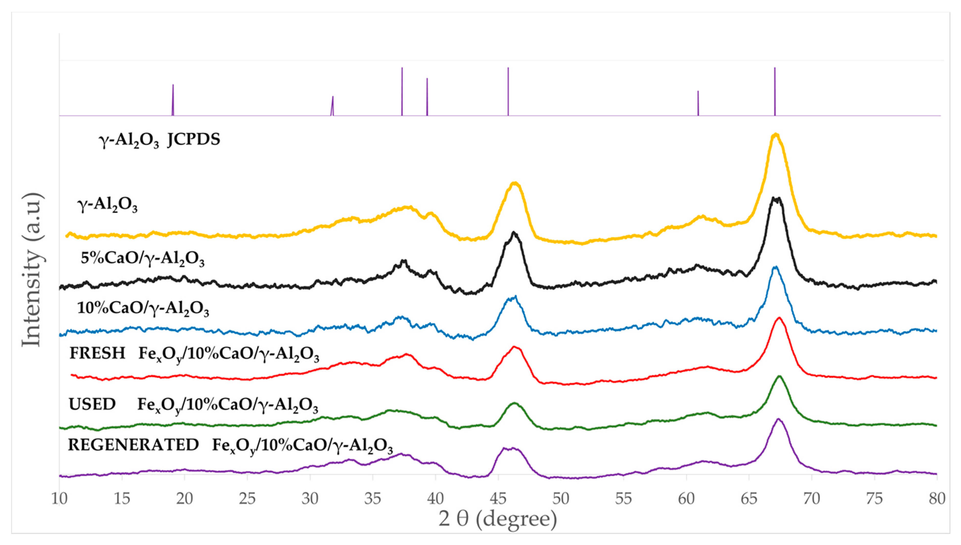
Figure 2 reports the XRD of the crystal phases present in the FexOy/CaO-γ-Al2O3 catalyst. XRD allowed us to analyze the catalyst and catalyst precursors at various stages of catalyst preparation and utilization, as follows: (a) the γ-Al2O3 support as received, (b) the γ-Al2O3 with added CaO, (c) the fresh FexOy/CaO-γ-Al2O3 catalyst, (d) the catalyst after usage, and (e) the catalyst following regeneration.
In Figure 2, one can observe the characteristic γ-Al2O3 XRD broad bands at 37.6°, 45.8°, and 67.1° of the 2θ scale (JCPDS 10-0425). As for CaO, while the 38° and 68° peaks may suggest a crystalline phase, all other CaO anticipated peaks at 32.5° (111), 54° (202), and 64° (311) are not present. As a result, an amorphous CaO phase, or, eventually, a microcrystalline phase below XRD’s detection limits, is considered to be possibly present. Furthermore, the predominant peaks at 43.20° for Fe, at 33.2°, 35.6°, 40.9°, and 49.5° for Fe2O3, and at 30.1°, 35.5°, and 57.1° for Fe3O4 (JCPDS file, No. 33-0664, JCPDS file, No. 19-0629, respectively) were not detected either. This further suggests the presence of amorphous iron containing phases or crystalline phases below detection limits. This was considered possible given the low nominal Fe concentration added to the γ-Al2O3 support.
Additionally, there were no strong Fe/Al2O3 XRD lines observed, with this showing the low probability of iron aluminate formation. This was consistent with previous studies with CaO- Fe2O3-Fe3O4 catalysts [60], which indicated the importance of limiting temperature increases during catalyst preparation, as practiced in the present study.
Therefore, the XRD’s positive identification of various added dopants as crystalline phases was not conclusive, and other additional techniques are required in order to clarify this matter, as will be described in the upcoming sections of this study.

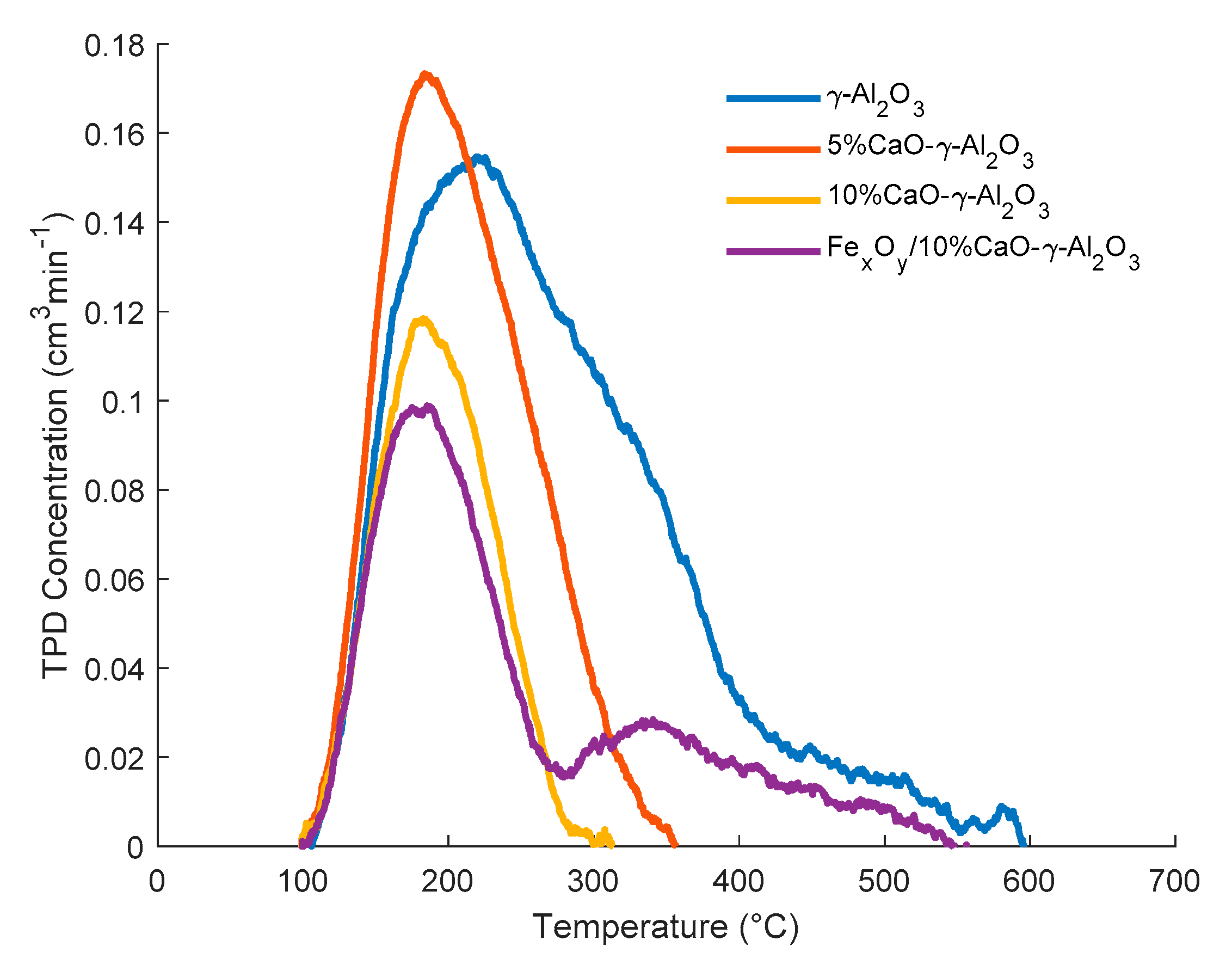
2.3.3. Influence of CaO and Iron Dopants on Acidity

Acidity reduction in a tar reforming catalyst is critical to achieve a decrease in coke formation. The evaluation of the effectiveness of CaO addition on acidity reduction was conducted using NH3-Temperature-Programmed-Desorption (NH3 pKa = 9.2 at 25 °C, in an aqueous solution [61]). Table 2 and Figure 3 report the significant role played by CaO addition to achieve a γ-alumina acidity decrease of more than 62%.
One can note, as well, that in Figure 3, the addition of iron oxides reintroduces a modest increase in both total acidity and medium strength acidity.
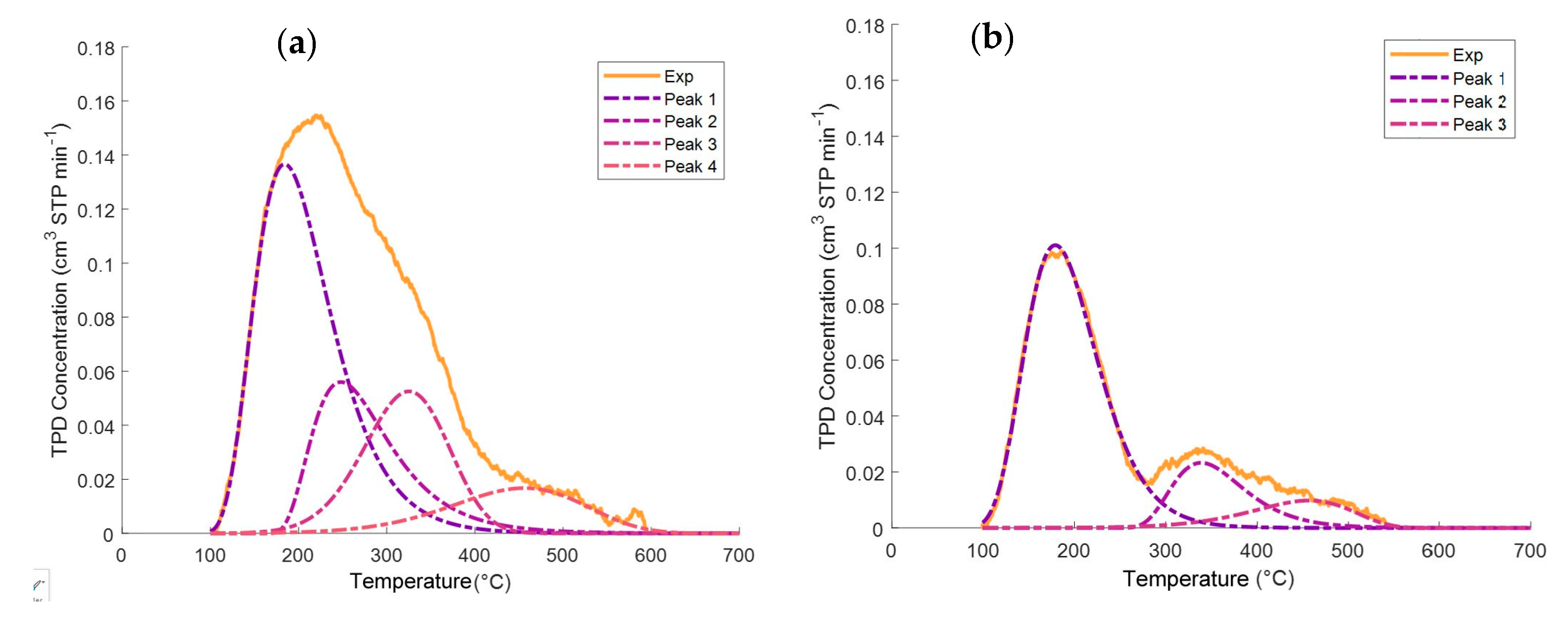
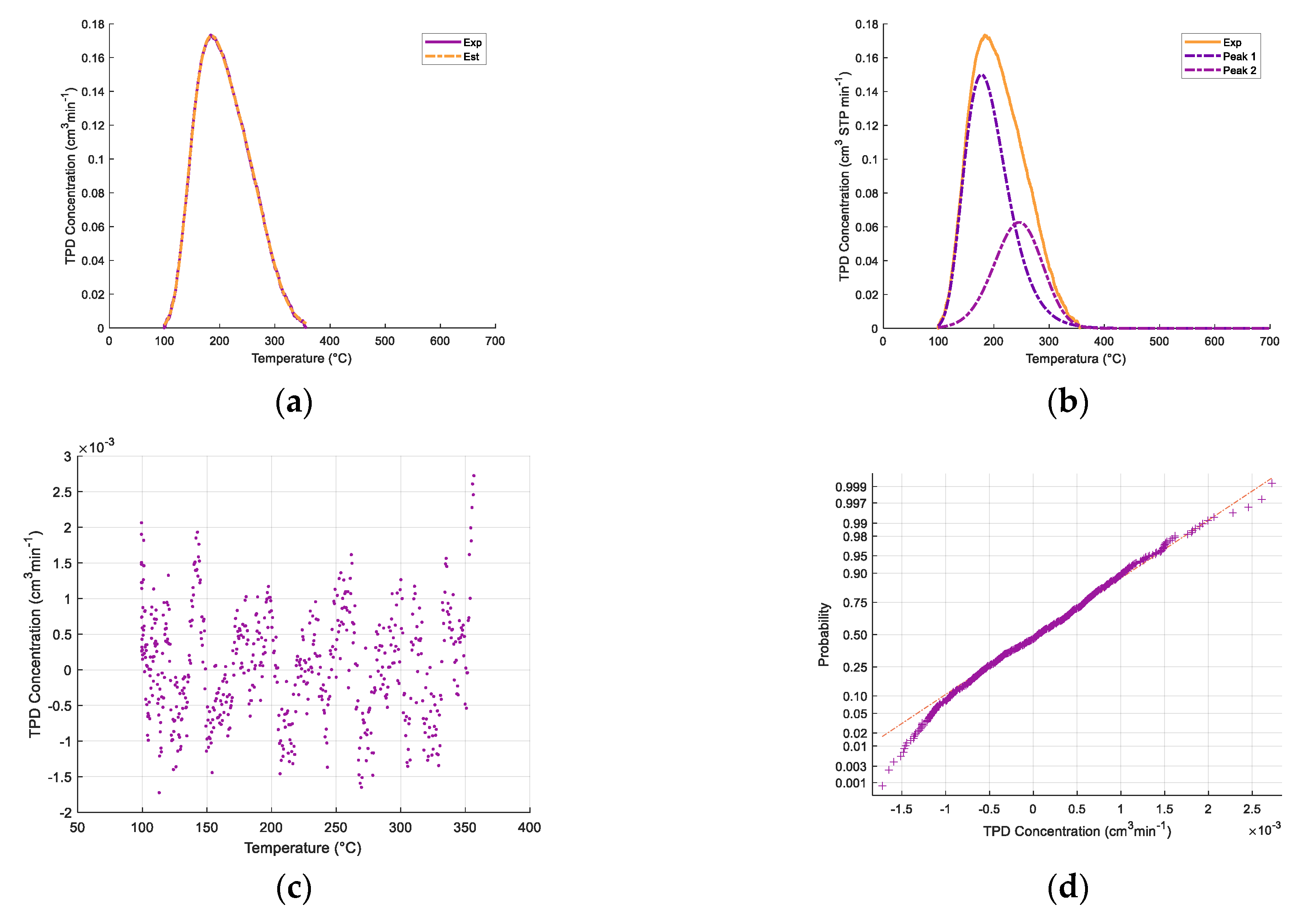
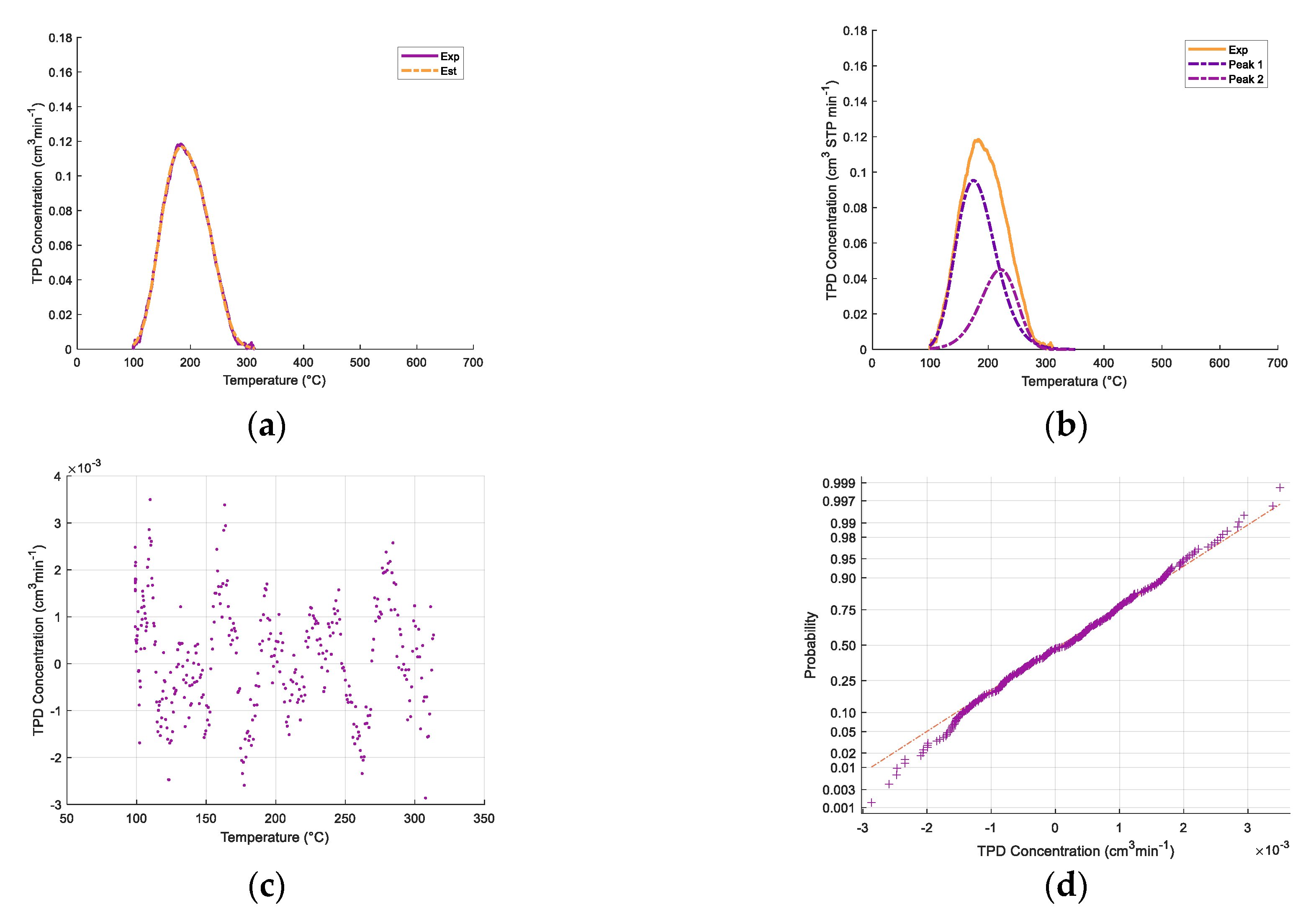
Figure 3 also shows that the relative contribution of various acid type sites is affected by both CaO and iron oxide addition. To quantify this effect, the broad ammonia desorption peaks were deconvoluted, considering four types of acidity sites. It was observed that the NH3-TPD curve deconvolutions provided in all cases a good NH3-TPD curve fitting, with random residuals, using three or four normal distribution functions. Regression coefficients were in all cases higher than 99%.
As described in Figure 4a,b, the NH3-TPD curve deconvolution suggests four types of acid sites for the γ-Al2O3 support and three types of FexOy/10% CaO-γ-Al2O3. Additional information regarding ammonia TPD deconvolution statistical parameters for 5% CaO/γ-Al2O3 and 10% CaO/γ-Al2O3 is provided in Appendix A.
Table 3 reports that in both the catalyst and various catalyst precursors of the present study, there are weak, medium, strong, and very strong acid site types.
Regarding the findings in Table 3, one should note that the TPD ammonia desorbed from the γ-Al2O3 support is in line with the studies of Peri et al. [62,63,64], who postulated for γ-Al2O3 several acid sites on alumina [65]. More recent works detected three coordinating sites and one protonic site on a γ-alumina support. These sites were considered too weak to be detected by pyridine adsorption. However, they were able to react with 2, 6 di-tertiary-butyl-pyridine (2,6T). It appears that two of the three coordinating sites interact with oxygen rather than aluminum and can be differentiated with 2,6T. The third weaker coordinating site reacts with pyridine only, given that it is closely associated with one or more hydroxyl groups [65,66].
In this respect, while using NMR, Majors and Ellis [67] deduced that the resonances observed in the γ-alumina support could be assigned to complexes containing coordinately unsaturated surface aluminum cations. These cations occupy tetrahedral and octahedral sites in the defect spinel lattice [68]. On the other hand, Coster el al. reported that different structural environments for a given Al site on the γ-alumina support yield a distribution of electric field gradient tensor parameters at the site, confirming the assumption that there are four types of aluminum site [69]. Furthermore, Digne et al. [66] postulated that both acid concentrations and strengths on the surface sites establish a γ-Al2O3 structure on the basis of experimental data and Discrete Fourier Transfer (DFT) simulations. In agreement with this, Wischert at al. [66] determined three different aluminum Lewis acid centers: (a) one AlIII, (b) two AlIVa and AlI
Vb, and (c) two- and threefold-coordinated O atoms with intrinsic Lewis basicity [70,71]. A fourth acid center was also identified and assigned to different acid center interactions. This is due to –HO positions that are apparently affected by alumina reactivity [70,72]. Furthermore, other authors claim that the relative distributions of tetrahedral and octahedral Lewis acid sites are functions of the surface preparation conditions [73].
Table 3 also reports the significant influence of CaO addition to the γ-Al2O3 support, which essentially eliminates from the γ-Al2O3 support the strong and very strong acid sites, with a significant reduction in weak and medium acid sites. It was also interesting to observe that when comparing the FexOy/CaO- γ-Al2O3 with the γ-Al2O3 support with added CaO, one could see that iron species addition reintroduced some strong acidity, as shown in the 1450 cm−1 and the 1600 cm−1 bands. The medium strength acid sites, however, disappeared, which is consistent with the Lewis iron species acidity in catalysis [74,75,76].
Thus, one can conclude that even though iron species addition restored some acidity, CaO was effective in reducing 59% of the strong and very strong acidity and 55% of the total support acidity.

2.3.4. Pyridine Desorption Infrared Spectroscopy

Pyridine proton affinity (PA) makes possible the use of pyridine protons as surface probe molecules (pKa = 5.3 at 25 °C in aqueous solution [61]) able to determine acidity type sites which are present in the solid catalyst [61]. Infrared spectroscopy of chemisorbed pyridine on γ-Al2O3 provides information regarding the nature of its surface acidity [61,77,78,79]. Therefore, in order to investigate the nature of the acid sites on the γ-Al2O3 support following CaO addition, pyridine FTIR analyses were performed. This was done by observing absorbance in the 1400–1700 cm−1 band range, typically assigned to Lewis site coke formation promoters [56].
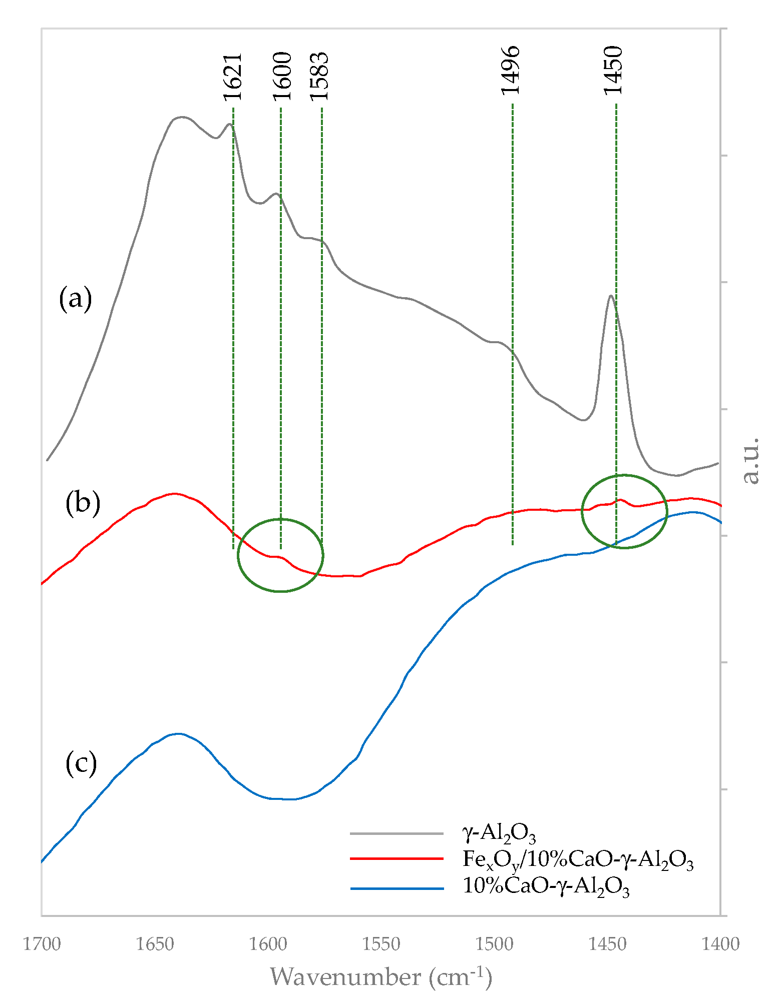
Figure 5 displays the typical IR bands for γ-Al2O3 at 1621 cm−1, 1600 cm−1, 1583 cm−1, 1496 cm−1, and 1450 cm−1 wave numbers assigned to coordinated bonded pyridine (CBP) and hydrogen bonded pyridine (HBP) as follows: a) the 1621 cm−1 and 1600 cm−1 bands for CBP, b) the 1583 cm−1 and the 1496 cm−1 bands for CBP and HBP, and c) the 1450 cm−1 band for HBP. For the sample with CaO added, no band at 1450 cm−1 was observed. This indicates that there are no Lewis acid sites remaining on the calcium oxide modified γ-Al2O3 support with the required strength to form pyridinium ions [71,77,80]. Furthermore, and according to Mazumder and de Lasa, the acid character in band 1621 cm−1 can be associated with very strong acid sites, while peaks at 1600 cm−1 and 1583 cm−1 on the γ-Al2O3 support can be considered to be moderate and weak acid Lewis site types [81].
Figure 5 also shows that the introduction of CaO in the γ-Al2O3 bulk substantially reduces its acidic alumina character, with no IR bands being detected. However, it appears that with iron addition, some moderate acid is reintroduced, as shown in the 1450 cm−1 and 1600 cm−1 bands. It is believed, nevertheless, that given the value of the eco-friendly catalyst in this study, further investigations are warranted in order to determine the precise catalyst structure changes, elucidating the potential sterical constraints.

2.3.5. Chemical State of Catalyst Species

Based on the present study’s eco-friendly catalyst for tar reforming, it was considered adequate to evaluate the catalyst using the fluidized CREC riser simulator in the 500–650 °C range. The catalyst was frequently contacted with oxygen from air, in order to combust the formed coke. Furthermore, both catalyst reactivity and stability were also evaluated, using hydrogen TPR/TPO (Temperature Programmed Reduction/Temperature Programed Oxidation) analysis, with a 20 °C/min temperature ramp and a maximum temperature close the one during runs in the CREC riser simulator.
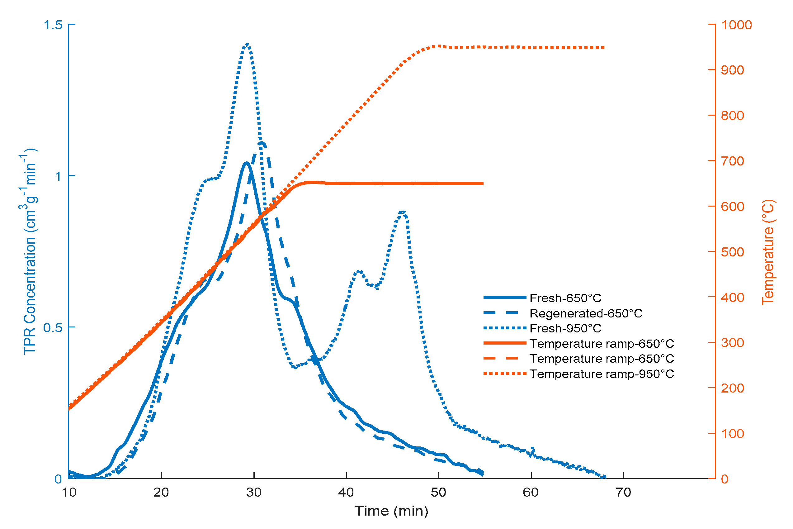
Figure 6 reports the sequential FexOy/10% CaO-γ-Al2O3 catalyst reduction–oxidation using TPR and TPO, with a 650 °C upper temperature. One can observe that the amounts of hydrogen consumed with the fresh and used catalysts after re-oxidation, as reported in Table 4, were very close: 15.15 cm3 STP H2 for the fresh catalyst and 14.6 cm3 STP H2 for the re-oxidized catalyst. One can also observe that the TPR peaks for both the fresh and the regenerated catalyst were essentially identical. This supports the view that the amounts of iron species available for the reaction with the 2M4MP remain unchanged following coke combustion and catalyst pre-reduction.
Furthermore, and considering the need to establish how the loaded iron value compared with the nominal iron value expected to be impregnated, TPR experiments were carried out at 950 °C, using the same 20° C/min temperature ramp. It was anticipated that under these conditions, all iron species present would be fully reduced to metallic iron:
F e 2 O 3 + 3 H 2 2 F e + 3 H 2 O
Table 4 reports the hydrogen consumed via TPR when using a fresh catalyst and when the upper TPR temperature was 950 °C. On this basis, one could calculate a 4.14 wt% metallic iron content, which is very close to the anticipated 4 wt% iron nominal loading value. This provides confirmation that the proposed catalyst’s incipient wetness impregnation technique with an iron precursor, as used in the present study, was adequate in order to reach the expected iron levels.
Another interesting result from Table 4 is the fact that iron species that were reduced to 650 °C only involved a hydrogen consumption which was about half the 4.14 wt% when the upper thermal level was 950 °C. This means that the state of the pre-reduced catalyst for 2M4MP conversion involves a significant amount of partially reduced iron species. In this respect, it is well known that iron reduction has multiple and simultaneous steps, with their extent of occurrence being a function of the upper reduction temperature and the reduction time [82,83,84,85]. Similar findings were obtained by Pineau et al. [83].
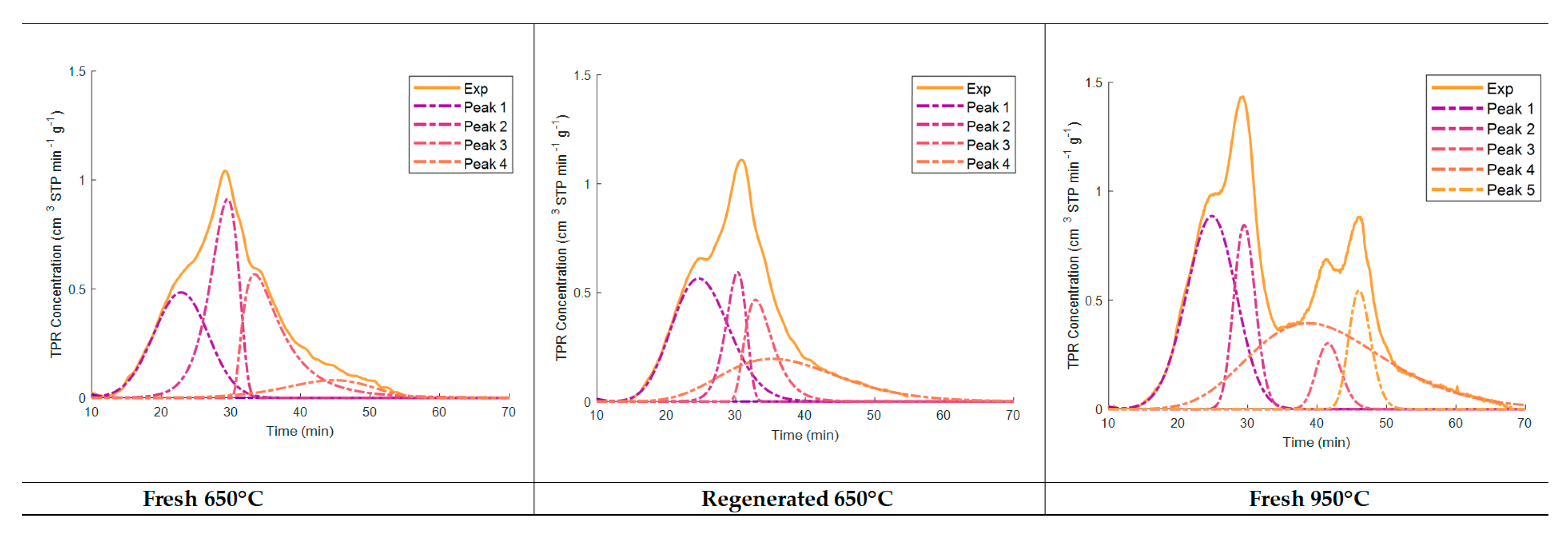
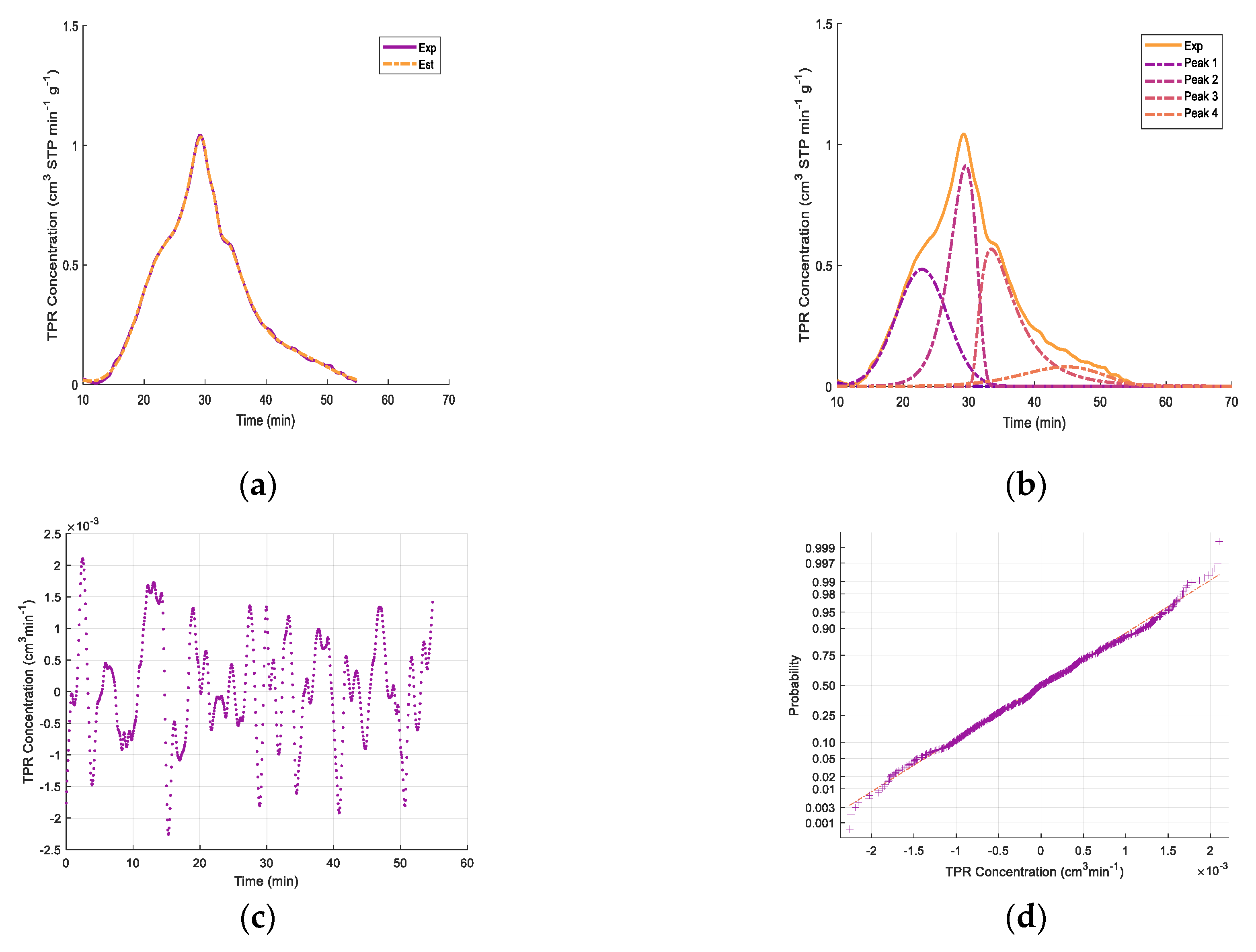
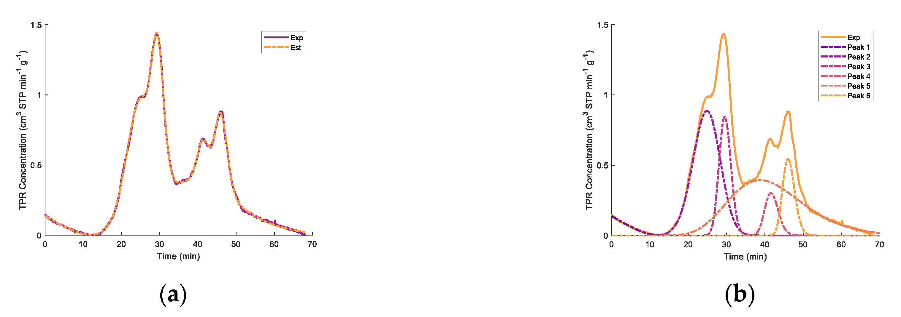
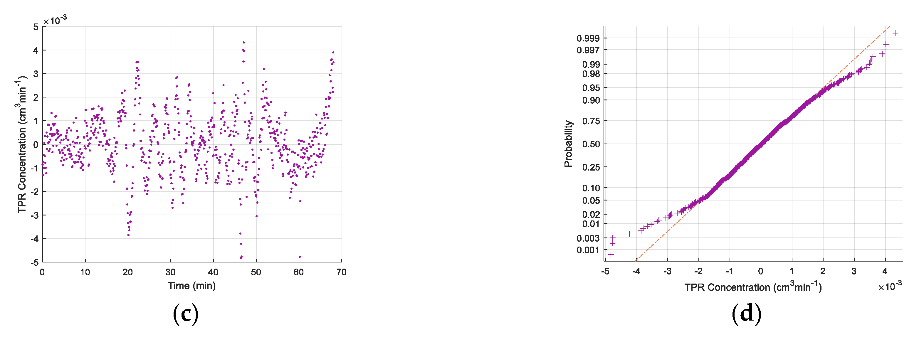
Regarding the TPR peaks, deconvolution was attempted in order to elucidate the reduction stages, as suggested by Jeong et al. [85] and Pineau at al. [82,83]. Figure 7 shows the deconvolution of the TPR peaks using normal probability distributions as well as random residuals. It was observed that the 650 °C upper temperature for both the fresh and regenerated catalysts involved TPR peak deconvolution, showing four significant reduction stages. As well as for catalyst TPRs with a 650 °C maximum temperature, differences were observed between the second peak and the third and fourth peaks, with the total TPR hydrogen consumption remaining close. This suggests the important extent of the reduction of the Fe2O3 species, with the fresh samples having a higher consumption of hydrogen in step 2 and the regenerated catalysts having a higher consumption of hydrogen in steps 3 and 4.
It appears that the polymorphous transformation of Fe2O3 to Fe3O4 starts with the removal of surface oxygen ions by hydrogen, followed by Fe (II) diffusion. Wei et al. [86] indicated that for iron oxide nanorods, the crystal structure of the Fe2O3 determines the rearrangements of iron cations and oxygen anions. In this case, a similar cubic structure evolves in a topotactic process without crystallographic change, making the migration of Fe (II) more energetically favorable. These iron oxides can provide reactivity [87,88,89,90,91], contributing to the catalyst activity.
The iron oxide reduction mechanisms may include an oxide hydroxide transformation into magnetite as one of the first reaction steps [92], as described in Equation (2):
2 F e O O H + F e + 2   F e 3 O 4 + 2 H +
Furthermore, and according to Equations (3) to (6), iron oxides (hematite) can be further reduced to magnetite, then to the stable F e ( 1 x ) O wüstite, and finally to iron metal [93], according to the percentage oxygen content. In this respect, the 570 °C thermal level appears to be of critical importance to determine the extent of these reactions [82,83,84,85,94,95]:
3 F e 2 O 3 + H 2 2 F e 3 O 4 + H 2 O
T < 570 °C
F e 3 O 4 + 4 H 2 3 F e + 4 H 2 O
T > 570 °C
( 1 x ) F e 3 O 4 + ( 1 4 x ) H 2 3 F e ( 1 x ) O + ( 1 4 x ) H 2 O
F e ( 1 x ) O + H 2 ( 1 x ) F e + H 2 O
Thus, given the 650 °C upper reaction temperature of the present study, we can expect, as observed via TPR, the influence of several successive steps, as described via Equations (3)–(6).
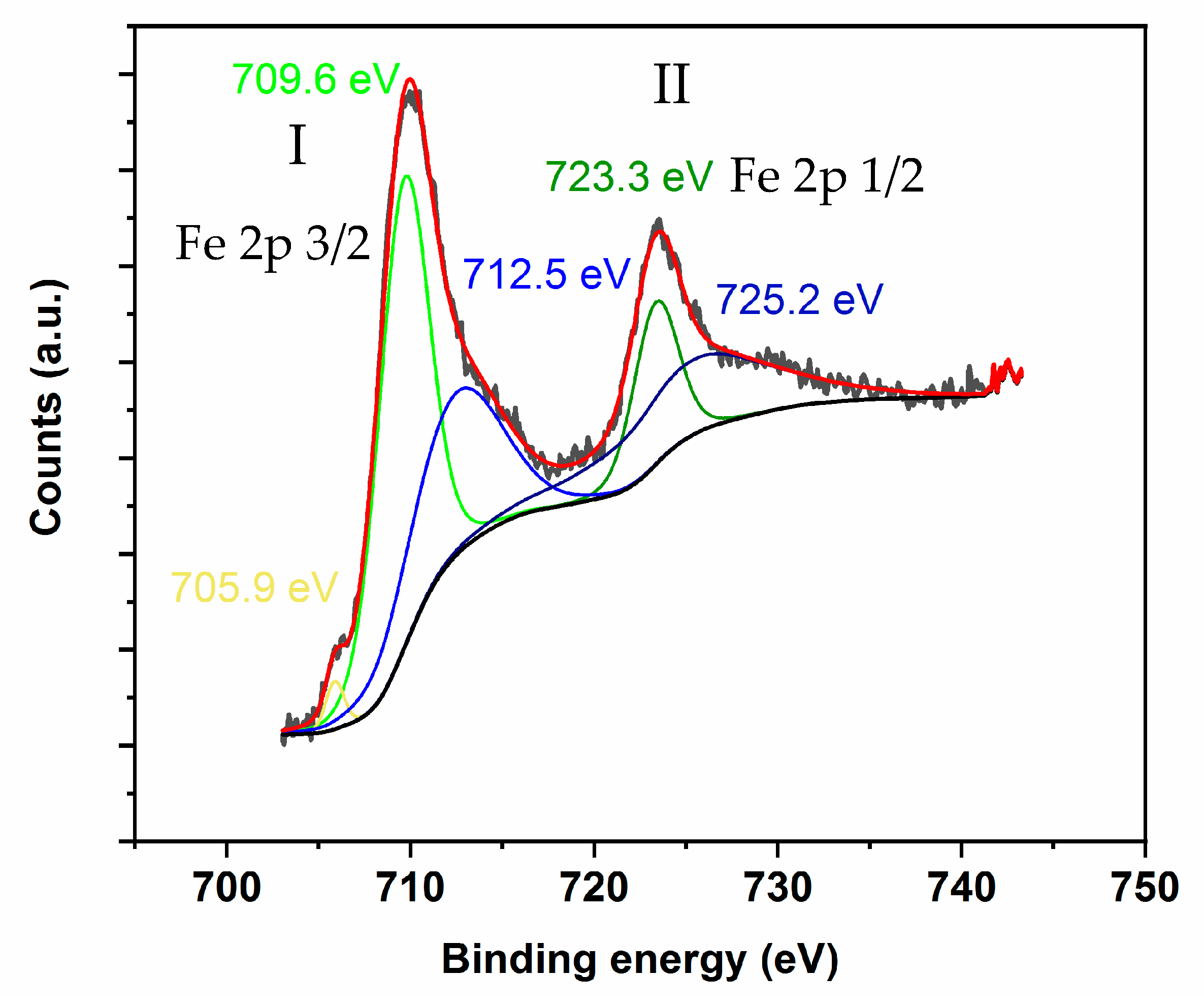
However, to ascertain more precisely the exact chemical state of the iron species following catalyst re-oxidation and partial reduction, an XPS analysis was developed, as shown in Figure 8. Results obtained by others allowed us to show that XPS can be used to analyze iron oxide species [96,97].
Figure 8 shows two major XPS peaks in the 703–733 eV energy binding bands: (1) the first one in the 704–717 eV binding energy range corresponding to Fe 2p 3/2 and (2) the second one in the 718–733 eV binding energy range assigned to Fe 2p 1/2. As for the high-resolution XPS spectra of Fe 2p, the peaks at the binding energies of 709.5 and 723.4 eV are characteristic of Fe(II) 2p3/2 and Fe(II) 2p1/2, whereas the peaks at 711.5 and 727.4 eV are assigned to Fe(III) 2p3/2 and Fe(III) 2p1/2, respectively [98,99].
Additionally, the peak at 706.1 eV can be assigned to metallic iron, while the peak at 717.4 eV can be attributed to a Fe 2p3/2 satellite peak [100]. This is consistent with the presence of the iron species on the catalyst’s surface, as observed by XPS, displaying mixed valences as (Fe3+) tetra and (Fe2+Fe3+) OctaO4, with Fe3+ and Fe2+ XPS [101]. Thus, the XPS results obtained for the pre-reduced catalyst at 650 °C can be assigned to an iron species blend, likely Fe3O4, FeO, and Fe, together with the unconverted Fe2O3. These XPS findings are in line with the research of Fujii et al. [101], where it was shown that the 709 eV main XPS peak is proportional to the Fe2+ ions formed. The XPS peaks observed in our study are also consistent with Grosvenor et al. [102], who described an XPS Fe(II) 2p1/2 satellite peak.
Therefore, on the basis of the XPS data and as shown in Figure 8 using peak deconvolution, one can establish that for the 650 °C pre-reduced catalyst, one achieves a Fe+2/Fe3+ = 1.592 blend composed of Fe2+ and Fe3+ iron species, with the FWHM (full width at half maximum) being in the adequate range for those species.
Furthermore, on the basis of the hydrogen consumed at both 650 °C and 950 °C, as described in Table 5, and as per the calculations reported in Appendix D [103], it can be predicted that the prepared catalyst at the selected conditions involves the following distribution of iron species: Fe0 = 50.41%, Fe2+-= 30.43%, and Fe3 + = 19.14%.

2.3.6. Evaluation of Catalytic Tar Reforming and Cracking

Lignin is a complex aromatic biopolymer that interferes with the operational conditions of biomass thermochemical processes [104,105,106] and promotes tar generation. The major compounds in tar are typically lignin-derived phenolic species, constituted of subproducts of incomplete depolymerization. The components p-hydroxyphenyl (H), guaiacyl (G), and syringyl (S) have been reported as the principal components of lignin [107,108,
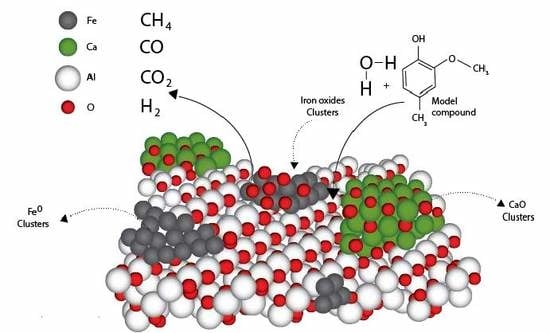
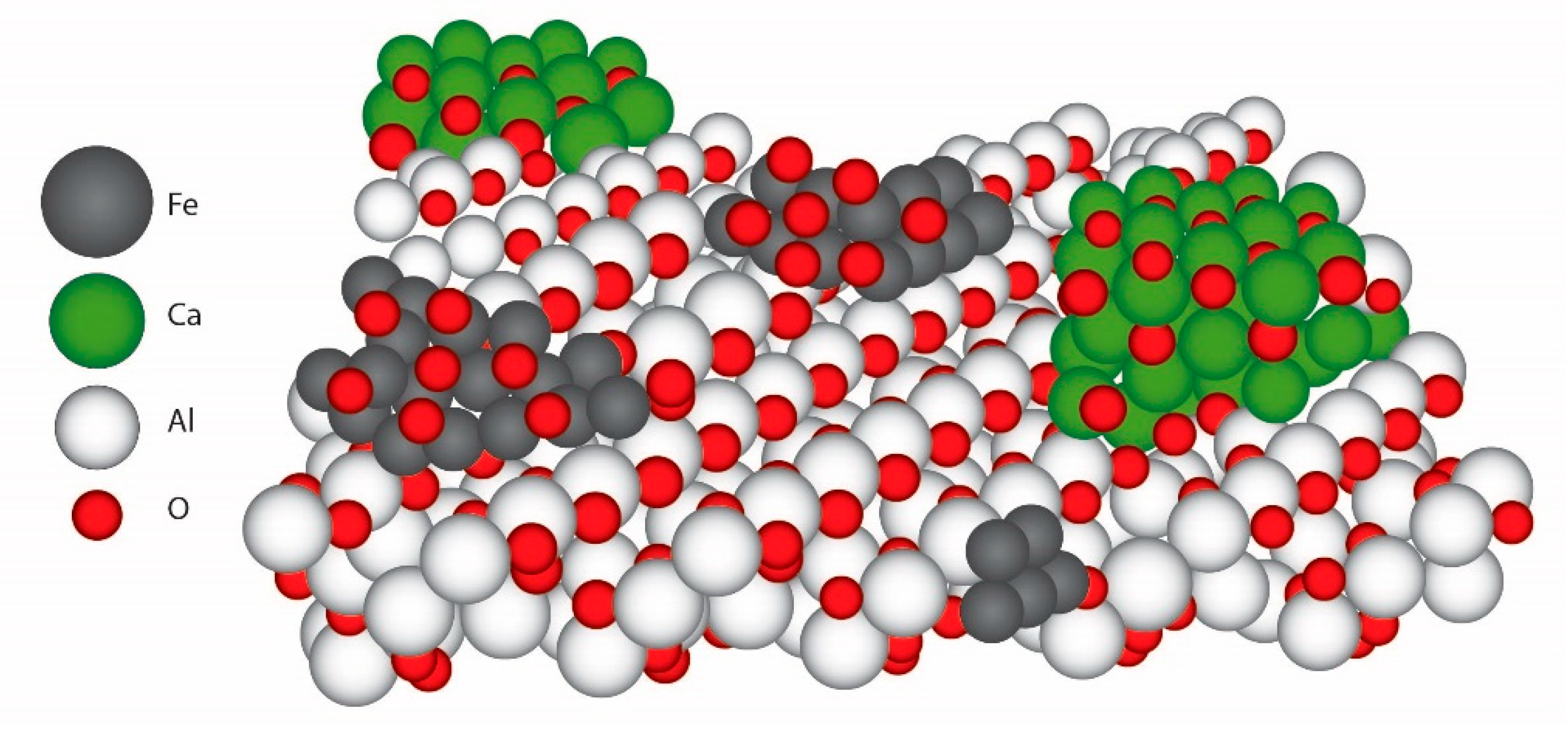
109]. The H, G, and S lignin units differ in the number of methoxyl substitutions. Therefore, 2-methoxy-4-methylphenol was used as a valid probe molecule or aromatic model compound to evaluate the catalyst performance for tar cracking, given that it contains typical chemical functionalities which are characteristic of tars: (a) aromatic rings, (b) -OH hydroxyl groups, (c) O-CH3 methoxy groups, (d) -CH3 methyl groups.
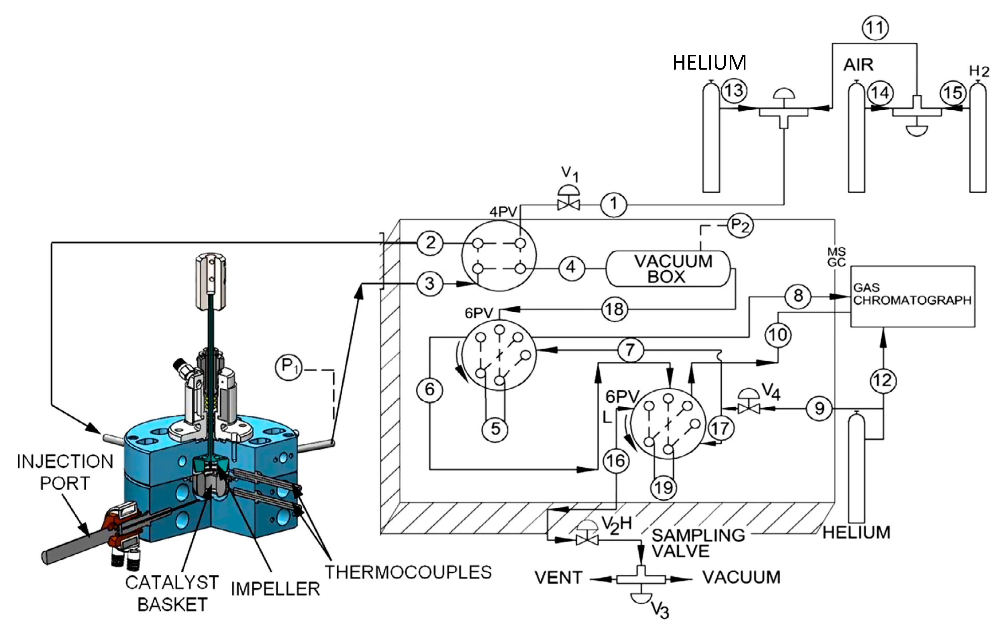
The performance of the developed catalyst was evaluated via several experimental runs developed in the CREC riser simulator. The conditions selected for the runs were the following: reaction time (3 s, 5 s, 7.5 s, and 10 s) and steam/biomass ratio (1.0 and 1.5). At least three repeats for every experiment were effected. After every run, the following were examined: product chemical gas composition, carbon conversion, and selectivity. It is expected that primary and some secondary tars can be formed at lower gasification temperatures. On this basis, 500 °C was selected and a 0.3 g catalyst load was chosen. In every experiment, the fluidization of the catalyst in the catalyst basket was ensured by setting the impeller speed as 5500 rpm.
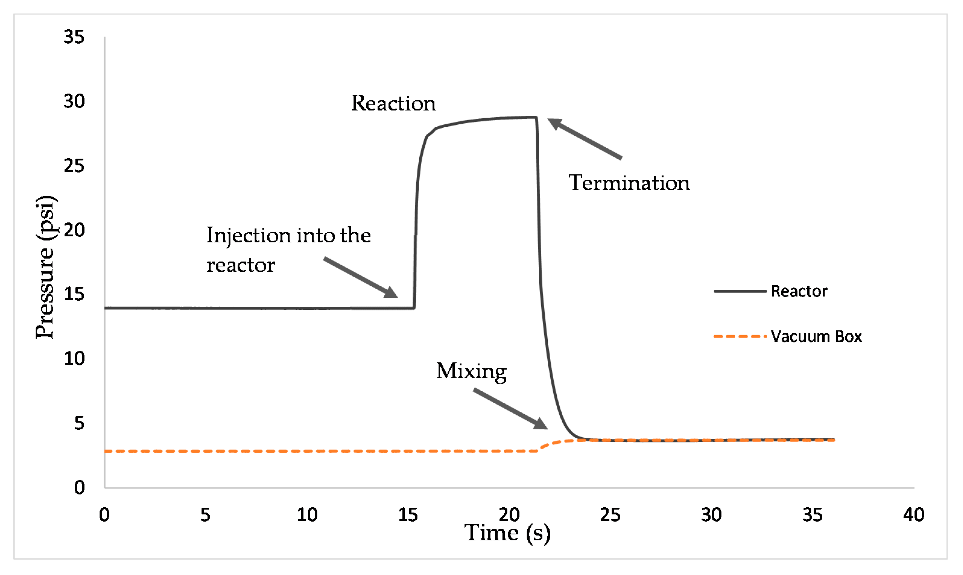
Figure 9 reports how total pressure changes with reaction time in a typical run in the CREC riser simulator. Total pressure readings and the determination of the composition of product species allowed us to perform mass balances and carbon balances closing in the 90%–107% range.

Conversion and Carbon Conversion Distribution

Tar gasification can be described as per Equation (7).
C 8 H 10 O 2 + β   H 2 O γ   H 2 + ν C O + µ   C O 2 + ε C H 4 + β C m H n O o   + δ C x H y O z
with C8H10O2 representing the surrogate tar 2M4MP model compound; H2, CO, CO2 and methane standing for the syngas components; C m H n O o accounting for the C2–C7 hydrocarbons resulting from both cracking and reforming; C x H y O z representing coke precursors species resulting from aromatic radical recombination.
Thus, catalyst performance can be examined using the 2M4MP conversion and the light molecular weight species selectivity. This was done using a rigorous approach based on carbon-containing gaseous product species, as described in the Methods section. Standard deviations for experimental repeats were in the 3%–12% range, with an average of 93% 2M4MP conversion for the catalytic runs. An important observation from these runs was the mass balance closures, which included H2, CO, CO2, H2O, CH4, C2–C7 species, and unconverted 2M4MP. Carbon deposited was in the (0.83 ± 0.3)% range.
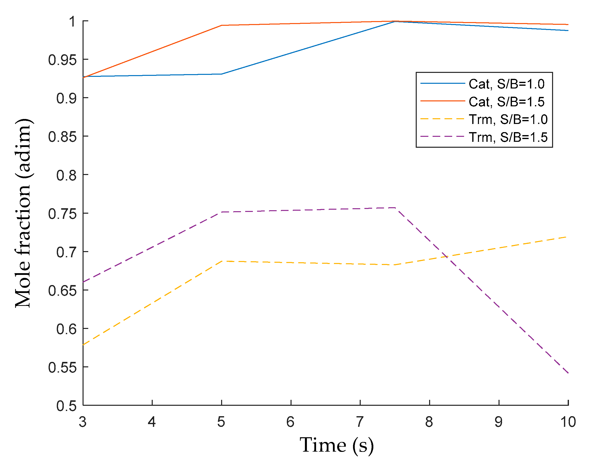
Figure 10 compares the 2M4MP conversions during thermal and catalytic experiments under fluidization conditions. It can be clearly seen that the 2M4MP conversions using the developed catalyst were significantly higher than those in thermal cracking experiments, with a difference of more than 30% in 2M4MP conversions, depending on the S/B ratio. It seems that the controlled acid sites in the FexOy/CaO-γ-Al2O3 catalyst contribute to better aromatic ring cracking. This is due to nucleophile interactions that take place with these chemical species, which can favor and stabilize the ring-opening mechanism in a steam environment [110,111].
Figure 10 reports the progressive 2M4MP thermal conversion increase with reaction time until it reaches 7.5 s. Following this, there is a moderately reduced conversion at 10 s. This 2M4MP thermal conversion decrease was assigned to the re-alkylation of the formed aromatic products. On the other hand, once the catalyst is loaded into the reactor, the thermal conversion increases consistently with reaction time, reaching 80% to almost 100% conversions, with a consistent trend of thermal conversion growing with the reaction time.
On the other hand, Figure 11 reports the carbon-containing products obtained at 500 °C. In this figure, the significant influence of the catalytic cracking and reforming reactions producing C1–C2 light gaseous species is noticeable. This is quite apparent at a 7.5 s reaction time, when comparing the catalytic and thermal runs: one should also notice that methane from the catalytic runs at S/B = 1.0 and S/B = 1.5 increases by almost two and three times those observed in the thermal runs.
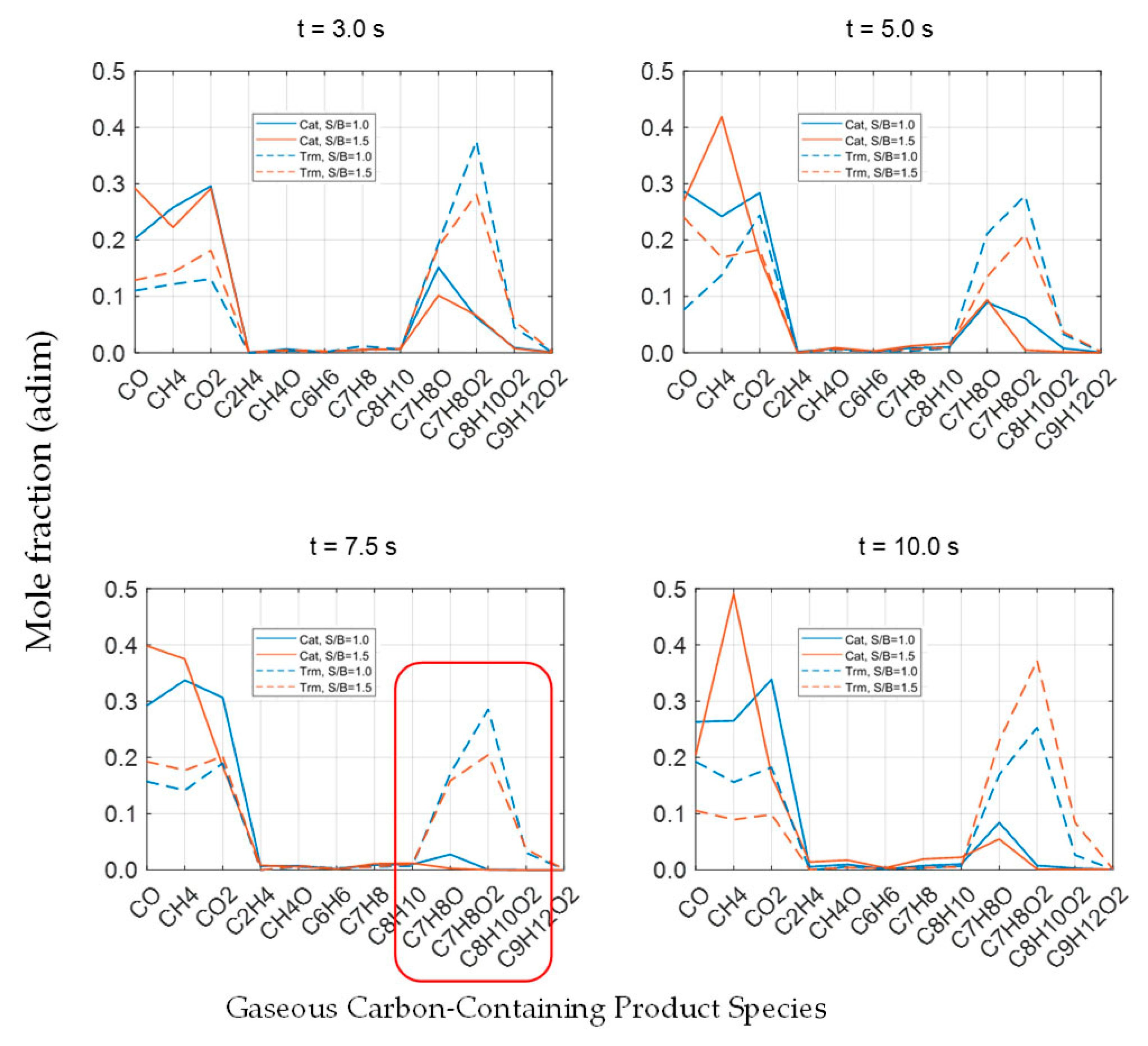
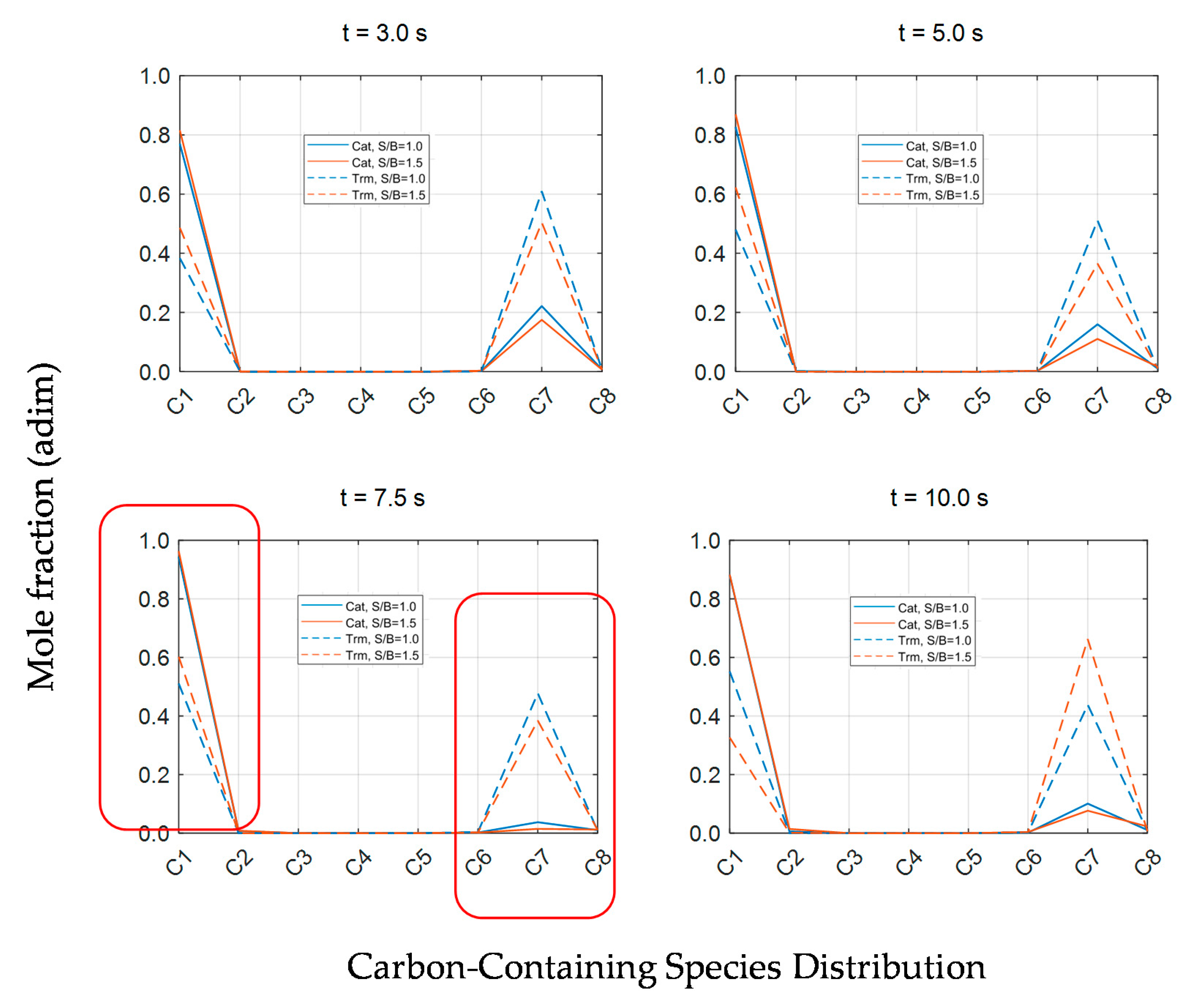
Furthermore, given the need for a better understanding of the various catalytic conversion processes for 2M4MP, the species molar fractions expressed as given carbon number fractions are shown in Figure 12. One can notice that, contrary to the thermal process, the presence of a catalyst not only contributes to obtaining very high 2M4MP conversions but also yields formed products dominated by the C1–C2 carbon number fraction.
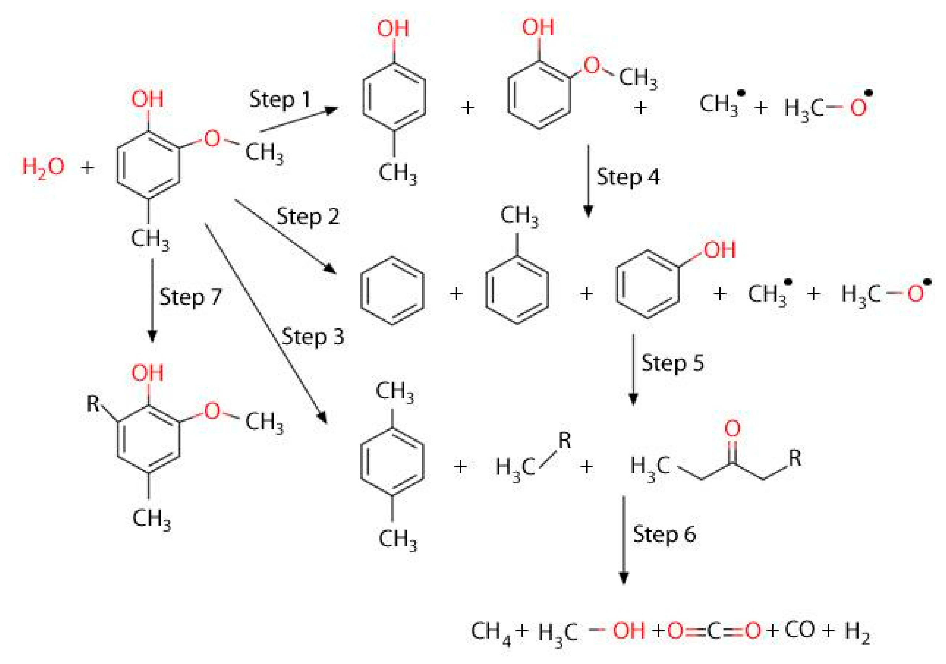
Based on the above reported results, and given the detected chemical species, one can identify simultaneous cracking/reforming reactions via a reaction network, as described in Figure 13. Hence, taking as a reference the product distribution found in 3 s duration runs, the first 2M4MP conversion steps are identified as being dealkylation reactions acting in parallel: these are steps 1, 2 and 3 in Figure 13. This leads to the formation of methyl and methoxy radicals. Following these first steps, benzene, toluene, cresol, and xylenes species are formed. These product species can additionally react with steam, further undergoing dealkylation steps, i.e., steps 4 and 5 in Figure 13. This provides, as a result, additional methyl and methoxy radicals for secondary reactions. However, given the reforming capabilities of the FexOy/CaO/γ-Al2O3 catalyst of the present study, aromatic rings are open, with most of the product species being in the C1–C2 range: this is described in steps 6 and 7. One should note that the reaction mechanism postulated in Figure 13 also accounts for the possible radical ring recombination leading to coke precursor formation.
Thus, one can notice that the FexOy/CaO-γ-Al2O3 catalyst of the present study, at the 5–7 s short contact time, envisioned in a downer or riser reactor, leads predominantly at 500 °C to the complete conversion of biomass-derived tar, with most of the formed products being in the C1–C2 range.

3. Materials and Methods

3.1. Materials

To emulate the natural derived ash, a set of biomass gasification ashes were analyzed using a EDXRF from Bruker S2 RANGER (EQUA Powder ALL > 100 ppm, Polycarbonate). The analysis was developed following the standard methods ASTM E871-82 and ASTM D 1102-84, recommended for the elemental inorganic species analysis. A γ-Al2O3 from Sasol Catalox® SSCa5/200, with a 53–70µm particle size, was used as a catalyst support, with Ca(NO3)2.4H2O (CAS 13477-34-4) and Fe(NO3)3·9H2O (CAS 7782-61-8) from Sigma-Aldrich being employed as Ca and Fe precursors, respectively. Finally, the 2-methoxy-4-methylphenol from Sigma Aldrich (CAS 13477-34-4) was used as a model compound to simulate biomass-derived tar.

3.2. Catalyst Preparation

In this study, the catalyst was prepared using an “incipient wetness” impregnation technique under vacuum conditions. This allowed the proper transport of the impregnating solutions into the support. In order to improve the γ-Al2O3 support’s acidity, the support was modified with the addition of 5 and 10 wt% CaO. Furthermore, once the CaO was incorporated into the alumina support, 4 wt% Fe was added.
Several steps were involved in each of the impregnations during catalyst preparation. These consisted of the following: (a) The setting of the required equipment, where a conical quartz flask with a lateral outlet was connected to a 250 mmHg vacuum system; (b) the addition of 20 g of γ-Al2O3 to a conical flask, with the flask inlet being sealed with a rubber septum; (c) the solid sample pre-treatment under vacuum at 60 °C for 40 min, to slowly remove both the moisture and the gases entrapped in the alumina support; (d) the extra drying of the solid sample by heating it at 120 °C for 1.5 h; (e) the preparation of both Ca(NO3)2·4H2O (CAS 13477-34-4) and Fe(NO3)3·9H2O solutions, in compliance with both nitrate decomposition stoichiometry and solubility requirements; (f) the addition of 10 mL of the prepared solutions to the solid sample, drop-by-drop, at ambient temperature, under vacuum and intense mixing, in agreement with the 0.5 mL/g support pore volume capacity; (g) next, the solid sample drying for 4 h, using a 0.5 °C/min ramp until 120 °C is reached; (h) the placing of the impregnated solids in a specially designed fluidized bed unit; (i) following this, the solid sample calcination under a 50 cm3/min air flow, with temperatures increasing in several steps from ambient to 650 °C for 12 h and maintained at 650 °C for an additional 4 h; (j) the subsequent iron reduction implemented using a 20 °C/min ramp and 50 cm3/min of H2 (balanced with helium), with the temperature augmented at 20 °C/min from ambient to 650 °C for 16 h and maintained at 650 °C for an extra 8 h. The described catalyst preparation method involved several impregnation steps (typically four), and this was given the limited pore volume of the alumina support. This was required in order to achieve the desired targeted calcium and iron loadings in the eco-friendly catalyst.

3.3. Catalyst Characterization

3.3.1. N2 Adsorption

Nitrogen adsorption measurements were carried out at 77 K in an ASAP 2010 Automatic Adsorption Analyzer (Norcross, GA, United States) from Micromeritics. Before the measurements, samples weighing from 0.15 to 0.20 g were placed in the degas port of the adsorption apparatus and degassed using the following temperature ramp: 30 min at 60 °C, 30 min at 100 °C, and then 2 h at 350 °C. The vacuum pressure reached in the degassing procedure was 4 mmHg. Adsorption isotherms were measured under the relative pressure (P/P0) range, based on the saturation vapor pressure, ranging from~10−6 to 1.

3.3.2. XRD Patterns

X-ray powder diffraction patterns were obtained on a Rigaku Miniflex Diffractometer (The Woodlands TX09. United States). using Cu Kα (λ = 0.15406 nm) radiation. A tube voltage of 40 kV and a tube current of 40 mA were used for each catalyst sample. The samples were scanned every 0.02 degrees from 10 to 90° degrees, with a scan time constant of 2 degrees/min. The identification of the γ-Al2O3, Fe, Fe3O4, Fe2O3, and CaO phases were obtained with the assistance of the Joint Committee on Powder Diffraction Standards (JCPDS) files.

3.3.3. X-ray Photoelectron Spectroscopy (XPS)

Chemical state X-ray photoelectron spectroscopic analysis of iron transition metals and the analysis of their oxides were carried out in a Kratos Axis Nova Spectrometer (Wharfside, GTM, U.K.), using a monochromatic Al K (alpha) source (15 mA, 14 kV). XPS probed the sample surface to a depth of 5–7 nm. It had detection limits ranging from 0.1 to 0.5 atomic percent, depending on the element. The instrument’s work function was calibrated to give a binding energy (BE) of 83.96 eV for the Au 4f7/2 line made of metallic gold. The spectrometer dispersion was adjusted to give a BE of 932.62 eV for the Cu 2p3/2 line made of metallic copper. The Kratos Charge Neutralizer System was used in all the specimen analyses. Survey scan analyses were carried out, with an analysis area of 300 × 700 microns and a pass energy of both 160 eV and 20 eV. Spectra were charge corrected using the main carbon 1 s spectrum (adventitious carbon) set to 284.8 eV. The obtained spectra were analyzed using the Casa XPS software (version 2.3.14).

3.3.4. Temperature Programmed Experiments

Temperature programmed studies (TPR, TPO, and CO2 pulse chemisorption) were performed using a Micromeritics AutoChem II 2920 Analyzer (Norcross, GA, United States). A catalyst sample weighing 150–200 mg was placed in a U-shaped quartz reactor tube. This tube was then attached to the sample analysis port of the instrument, which was located inside a heating element. For NH3-TPD, the sample was pretreated under a 50 cm3/min helium flow, with the temperature being progressively increased until it reached 600 °C. Then, the sample was cooled to 100 °C for ammonia adsorption. A 5% NH3/He gas mixture was brought to saturation under a 50 mL/min flow rate for 1 h. After this step, the gas was changed to helium, at the same flow rate and temperature, for 1 more hour. This was done to remove the physically adsorbed NH3. The temperature was then raised to 650 °C, at a rate of 15 °C/min, with NH3 being desorbed progressively. The NH3 concentration in the effluent gas was monitored using a TCD (Thermal Conductivity Detector). The total acidity was established by accounting for the total amount of NH3 desorbed from the catalyst, using both a calibration curve and experimental recorded baseline.
In the case of H2, TPR was performed using the same automated equipment as the TPD experiments. During each experiment, 140−150 mg of a catalyst sample was in contact with a 10% H2/Ar gas mixture, at a flow rate of 50 mL/min. The sample was heated at a 20 °C/min rate until it reached the experimental temperature. The samples were analyzed at 650 °C and 950 °C. H2 consumption was monitored using a thermal conductivity detector (TCD). The amount of H2 uptake by the sample was calculated via the numerical integration of the TPR area.

3.3.5. Pyridine Fourier Transform Infrared Spectroscopy (FTIR)

The catalyst surface acid site type was determined using FTIR. Pyridine was used as a probe molecule. The catalyst sample was dried for 2 h under a H2/He flow at 650 °C, using the same reducing cycle as the one employed for its performance evaluation. Then, it was cooled to 100 °C. The sample was kept at this temperature and saturated with pyridine, using a nitrogen stream containing the probe molecule. The adsorption of pyridine was allowed for 1 h. Then, the samples were flushed with pure helium at 100 °C for 90 min in order to remove unbounded pyridine. The catalyst samples were dispersed on a potassium chloride window. Following this, the samples were analyzed by FTIR, using a Bruker Hyperion 2000 Microscope attached to a Tensor II main box (Ettlingen, Baden-Württemberg, Germany).

3.4. Tar Cracking Evaluation

The CREC riser simulator is a bench-scale mini-fluidized bed reactor. This automated unit records and accurately controls the reaction times in the 2–10 s range. This is an excellent tool for catalyst evaluation and kinetic studies, at the expected turbulent fluidized bed conditions of an industrial scale riser or downer fluidized bed gasifier. The reactor volume is 50 cm3 (Figure 14). A detailed description of the CREC riser simulator can be found in the literature [112,113,114,115]. A catalytic run in the CREC riser simulator can be divided into three time periods: (a) the injection period, (b) the reaction period, (c) the sampling period. As a result of the rapid transfer of the chemical species to the vacuum box, the progress of the reaction is essentially arrested.
In order to evaluate the reactivity and the stability of the prepared catalyst under gasification operating conditions using the CREC riser simulator, FexOy/CaO-γ-Al2O3 catalysts, already thermally treated during the preparation process, were loaded into the catalyst basket. The reactor system was sealed, leak-tested, and heated to the reaction temperature under a helium atmosphere. Then, the feed was injected, and once the reaction time was reached, the reaction products were evacuated from the reactor to the vacuum box. The steam cracking of a lignin biomass model compound (2-methoxy-4-methylphenol or 2M4MP) was performed in the reactor, under two steam/biomass ratios: 1.0 and 1.5 at 500 °C. A loading of 0.3 g of a /CaO-γ-Al2O3 catalyst was used. Reactor and vacuum box pressure data against time were recorded by FexOy the Personal Daq Acquisition Card. Once the set reaction time elapsed (e.g., 10 s), the products were quickly evacuated to the vacuum box. From the vacuum box, gas samples were sent to a GC-MS (Gas Chromatography- Mass Spectrometry) system via heated transfer lines. The GC-MS system is equipped with a packed-bed column (HaysSep® D) and a capillary column (BPX5). The packed-bed column is connected to a thermal conductivity detector (TCD) and the capillary column is connected to a mass spectrometer (MS). Coke deposited on the catalyst after the experimental runs was measured as CO2 in a total organic carbon analyzer (TOC-V), using a solid sample module (SSM-5000) from Mandel. To remove the deposited coke, a catalyst regeneration cycle was performed after every run. Regeneration experiments were run under the following conditions: 15 min of air flow to combust the coke first, followed by 30 min of hydrogen flow to reduce the catalyst at 650 °C. Experiments in the CREC riser simulator were repeated at least 3 times to secure the reproducibility of the results for each condition.
Catalyst performance was examined based on model compound conversion and light carbon fraction selectivity. Selectivity was calculated based on carbon-containing gaseous product species as follows:
  2 M 4 M P   C a r b o n   B a s e d   C o n v e r s i o n ,     X C 8 H 10 O 2 = 1 8 · n C 8 H 10 O 2 i ν i n i
M o l a r   C a r b o n   F r a c t i o n   o f   i   s p e c i e s =   y j = ν j n j i ν i n i
C a r b o n   B a s e d   S e l e c t i v i t y   f o r   i   species = S i = ν j n j i ν i n i ,         ν < 8
where n i represents the moles of carbon atoms in the gaseous carbon-containing product species i , ν i is the number of carbon atoms in the gaseous carbon-containing product i , n C 8 H 10 O 2 stands for the moles of unconverted 2M4MP in the product, and y j is the molar fraction of carbon species j in the total carbon content of the reaction system.

4. Conclusions

(a)
A fluidizable FexOy, CaO doped, γ-Al2O3 supported catalyst, designated as FexOy/CaO-γ-Al2O3, was successfully developed. This catalyst can steam gasify methoxy-4-methylphenol, which is a model probe biomass-derived tar, with 99.95% conversion at 500 °C and S/B ratios of 1.5 and 7.5 s.
(b)
At these conditions, gasification yields C1-C7 species, with no significant tar remaining and 0.98% carbon deposited as coke.
(c)
The developed FexOy/CaO-γ-Al2O3 catalyst performs close to thermodynamic equilibrium, yielding a 96.98% C1-C2 light-fraction product selectivity.
(d)
This catalyst also shows excellent stability under repeated gasification and regeneration cycles, which are the expected operating conditions of a circulating fluidized bed gasifier.
(e)
Up to 10 wt% CaO addition helps to reduce the thermal sintering and the Lewis acidity of the γ-Al2O3 support as well as to improve its basicity. Furthermore, controlled CaO addition has a positive impact on acid-base properties, limiting pore blocking by coke.

Supplementary Materials

The following are available online at https://www.mdpi.com/2073-4344/10/7/806/s1: Table S1: Typical Ash Chemical Composition Obtained during Gasification Runs of Different Biomass Using a Downdraft Gasifier Operated in Costa Rica, using XRF.

Author Contributions

C.T. developed the catalyst concept, the experimental methodology, the data interpretation, and preparation of the manuscript draft. S.R. collaborated with the development of TPR, TPO, and BET analyses. H.d.L. participated in the co-development of the catalyst concept, the data interpretation, and discussion and review of the manuscript draft. All authors have read and agreed to the published version of the manuscript.

Funding

This research received funding from the Universidad de Costa Rica, supporting C.T.’s doctoral research and periodic stays in Canada. The Natural Sciences and Engineering Research Council of Canada (NSERC-Canada) supported this research via H.d.L.’s Discovery Grant, to defray the materials and supplies required for the experimental research.

Acknowledgments

The authors gratefully acknowledge the assistance of F. Rojas with the experimental work, that of R. Quddus with impregnation procedure insights, the help of R. Urcuyo with the interpretation of the XPS results, and the support of L. Urvina with the specialized software programming. The authors are also thankful to Florencia de Lasa for her assistance with the editing of the present manuscript.

Conflicts of Interest

The authors declare no conflict of interest.

Abbreviations

AcronymDescriptor
2M4MP2-methoxy-4-methylphenol
BETBrunauer–Emmett–Teller
XRDX-ray diffraction
TPDTemperature programmed desorption
TPRTemperature programmed reduction
TCDThermal conductivity detector
NMRNuclear magnetic resonance
DFTDensity-functional theory
TPOTemperature programmed oxidation
XPSX-ray photoelectron spectroscopy
FWHMFull width at half maximum
JCPDSJoint Committee on Powder Diffraction Standards
FTIRFourier-transform infrared spectroscopy
CRECChemical Reactor Engineering Centre
TOCTotal organic carbon
PAHsPolyaromatic hydrocarbons
STPStandard temperature and pressure
PAPyridine proton affinity
CBPCoordinated bonded pyridine
HBPHydrogen bonded pyridine
Hp-hydroxyphenyl
GGuaiacyl
SSyringyl
EDXRFEnergy dispersive X-ray fluorescence

Appendix A. Deconvolution of NH3-TPD Desorption Peaks

Figure A1 and Figure A2 report the ammonia TPD desorption peaks with their respective deconvolutions for 5% CaO/ γ-Al2O3 and 10% CaO/ γ-Al2O3 and their statistical parameters of interest.
Figure A1. Deconvolution of the NH3 -TPD curve for 5% CaO/ γ-Al2O3. (a) Adjustment curve with R2 = 1.00, (b) composition curves, (c) regression residues, (d) Probability distribution of the adjustment curve selected.
Catalysts 10 00806 g0a1
Figure A2. Deconvolution of the NH3 -TPD curve for 10% CaO/ γ-Al2O3. (a) adjustment curve with R2 = 0.999, (b) composition curves, (c) regression residues, (d) probability distribution of the adjustment curve selected.
Catalysts 10 00806 g0a2

Appendix B. Deconvolution of TPR for FexOy/CaO- γ-Al2O3 Catalysts

Figure A3 and Figure A4 report the TPR curves for the 4% Fe/10% CaO-γ-Al2O3 catalyst with 650 °C (regenerated sample) and 950 °C (fresh sample respectively) as maximum temperatures, respectively. TPR curves were analyzed using a multi-peak deconvolution method, with statistical parameters for this deconvolution being determined as reported in Figure A3 and Figure A4.
Figure A3. Deconvolution of the TPR plot with 650 °C as maximum temperature, for a regenerated 4% Fe/10% CaO- γ-Al2O3 catalyst sample. Deconvolution of the TPR plot, with 650 °C as maximum temperature for a regenerated 4% Fe/10% CaO- γ-Al2O3 catalyst sample: (a) adjustment curve with R2 = 0.9995, (b) composition curves, (c) regression residues, (d) probability distribution of the adjustment curve selected.
Catalysts 10 00806 g0a3
Figure A4. Deconvolution of the TPR curve, with 950 °C as maximum temperature for a fresh 4% Fe/10% CaO- γ-Al2O3 catalyst sample: (a) adjustment curve with R2 = 0.9996, (b) composition curves, (c) regression residues, (d) probability distribution of the adjustment curve selected.
Catalysts 10 00806 g0a4aCatalysts 10 00806 g0a4b

Appendix C. Coke Deposition and Iron Evaluation

Figure A5 reports the change in appearance of the γ-Al2O3 support once the CaO at 10% was added, with a significant reduction in coke formation.
Figure A5. Coke deposition after 30 s of reaction time, at 500 °C in the CREC riser simulator: (a) γ-Al2O3, (b) 10% CaO- γ-Al2O3. Note: model compound: 2M4MP, S/B = 1.0.
Catalysts 10 00806 g0a5

Appendix D. Evaluation of Fe0, Fe2+, and Fe3+ Distribution Using XPS and TPR Data

In order to calculate the relative of Fe0, Fe2+, and Fe3+, the following approach was used:
(a)
The β’ = Fe2+/Fe3+ ratio was established using XPS, as described on page 14.
(b)
The µ fraction = moles of H2 consumed with TPR at 650 °C/moles of H2 consumed with TPR at 950 °C was assessed as γ’ = (0.5β + 1.5α’)/1.5(1 + α’ + β’).
(c)
Given this, and rearranging the γ’ equation, the α’ was calculated as α = Feo/Fe3 + = (1.5γ’(1 + β’)-0.5β’)/(1.5(1-γ’)).
(d)
Then, on the basis of (1+ α’+ β’)100 = (1+ Fe2+/Fe3+ Feo/Fe3+) 100 or Fe3+/(Fe+ Fe2+ + Fe3+)= Fe3+%.
(e)
Furthermore, considering (α’ Fe3+%) and (β’ Fe3+%), both the Fe2+% and Fe0% can be calculated as well.
In the case of the catalyst of the present study, given that β’= 1.592 and γ’= 0.605, the resulting elemental iron species compositions were as follows: Fe0 = 50.41%, Fe2+-30.43%, and Fe3+ = 19.14%.

References

  1. IRENA, I. Renewable Power Generation Costs in 2017; IRENA—International Renewable Energy Agency: Abu Dhabi, UAE, 2018. [Google Scholar]
  2. Torres, C.; Urvina, L.; Hernández, N.; Molina, D. Informe Técnico Evaluación de Desempeño de la Tecnología Comercial de Gasificación Utilizando Residuos de Café; Universidad de Costa Rica: San José, Costa Rica, 2016. [Google Scholar]
  3. De Lasa, H.; Salaices, E.; Mazumder, J.; Lucky, R. Catalytic steam gasification of biomass: Catalysts, thermodynamics and kinetics. Chem. Rev. 2011, 111, 5404–5433. [Google Scholar] [CrossRef]
  4. Tanksale, A.; Beltramini, J.N.; Lu, G.M. A review of catalytic hydrogen production processes from biomass. Renew. Sustain. Energy Rev. 2010, 14, 166–182. [Google Scholar] [CrossRef]
  5. Chan, F.L.; Tanksale, A. Review of recent developments in Ni-based catalysts for biomass gasification. Renew. Sustain. Energy Rev. 2014, 38, 428–438. [Google Scholar] [CrossRef]
  6. Chianese, S.; Fail, S.; Binder, M.; Rauch, R.; Hofbauer, H.; Molino, A.; Blasi, A.; Musmarra, D. Experimental investigations of hydrogen production from CO catalytic conversion of tar rich syngas by biomass gasification. Catal. Today 2016, 277, 182–191. [Google Scholar] [CrossRef]
  7. Li, S.; Zheng, H.; Zheng, Y.; Tian, J.; Jing, T.; Chang, J.-S.; Ho, S.-H. Recent advances in hydrogen production by thermo-catalytic conversion of biomass. Int. J. Hydrogen Energy 2019, 44, 14266–14278. [Google Scholar] [CrossRef]
  8. Li, C.; Suzuki, K. Tar property, analysis, reforming mechanism and model for biomass gasification-An overview. Renew. Sustain. Energy Rev. 2009, 13, 594–604. [Google Scholar] [CrossRef]
  9. Li, D.; Tamura, M.; Nakagawa, Y.; Tomishige, K. Metal catalysts for steam reforming of tar derived from the gasification of lignocellulosic biomass. Bioresour. Technol. 2015, 178, 53–64. [Google Scholar] [CrossRef] [PubMed]
  10. Evans, R.J.; Milne, T.A. Chemistry of Tar Formation and Maturation in the Thermochemical Conversion of Biomass. In Developments in Thermochemical Biomass Conversion; Springer: Dordrecht, The Netherlands, 1997; pp. 803–816. [Google Scholar]
  11. Abatzoglou, N.; Barker, N.; Hasler, P.; Knoef, H. The development of a draft protocol for the sampling and analysis of particulate and organic contaminants in the gas from small biomass gasifiers. Biomass Bioenergy 2000, 18, 5–17. [Google Scholar] [CrossRef]
  12. Maniatis, K.; Beenackers, A.A.C.M. Tar Protocols. IEA Bioenergy Gasification Task: Introduction. Biomass Bioenergy 2000, 18, 1–4. [Google Scholar] [CrossRef]
  13. Woolcock, P.J.; Brown, R.C. A review of cleaning technologies for biomass-derived syngas. Biomass Bioenergy 2013, 52, 54–84. [Google Scholar] [CrossRef]
  14. Rakesh, N.; Dasappa, S. A critical assessment of tar generated during biomass gasification—Formation, evaluation, issues and mitigation strategies. Renew. Sustain. Energy Rev. 2018, 91, 1045–1064. [Google Scholar] [CrossRef]
  15. Asadullah, M. Barriers of commercial power generation using biomass gasification gas: A review. Renew. Sustain. Energy Rev. 2014, 29, 201–215. [Google Scholar] [CrossRef]
  16. Anis, S.; Zainal, Z.A. Tar reduction in biomass producer gas via mechanical, catalytic and thermal methods: A review. Renew. Sustain. Energy Rev. 2011, 15, 2355–2377. [Google Scholar] [CrossRef]
  17. Mozaffarian, M.; Cameron, L.R.; Falzon, J.P.J.; Cohen, B.; Das, K.C.; Bole-Rentel, T. Biomass Waste-to-Energy Toolkit for Development Practitioners The Green House SNV Netherlands Development Organisation; ECN: Petten, The Netherlands, 2014. [Google Scholar]
  18. Sikarwar, V.S.; Zhao, M.; Clough, P.; Yao, J.; Zhong, X.; Memon, M.Z.; Fennell, P.S. An overview of advances in biomass gasification. Energy Environ. Sci. 2016, 9, 2939–2977. [Google Scholar] [CrossRef] [Green Version]
  19. Huang, S.; Wu, S.; Wu, Y.; Gao, J. Structure characteristics and gasification activity of residual carbon from updraft fixed-bed biomass gasification ash. Energy Convers Manag. 2017, 136, 108–118. [Google Scholar] [CrossRef]
  20. Pissot, S.; Vilches, T.B.; Thunman, H.; Seemann, M. Biomass and Bioenergy Effect of ash circulation on the performance of a dual fluidized bed gasification system. Biomass Bioenergy 2018, 115, 45–55. [Google Scholar] [CrossRef]
  21. Shahbaz, M.; Yusup, S.; Inayat, A.; Patrick, D.O.; Ammar, M. The influence of catalysts in biomass steam gasification and catalytic potential of coal bottom ash in biomass steam gasification: A review. Renew. Sustain. Energy Rev. 2017, 73, 468–476. [Google Scholar] [CrossRef]
  22. Heinze, T. Cellulose Chemistry and Properties: Fibers Nanocelluloses and Advanced Materials; Springer: Berlin/Heidelberg, Germany, 2016. [Google Scholar]
  23. Herman, A.P.; Yusup, S.; Shahbaz, M. Utilization of bottom ash as catalyst in biomass steam gasification for hydrogen and syngas production. Chem. Eng. Trans. 2016, 52, 1249–1254. [Google Scholar]
  24. Kryca, J.; Pri, J.; Joanna, Ł.; Kuba, M.; Hofbauer, H. Apparent kinetics of the water-gas-shift reaction in biomass gasi fi cation using ash-layered olivine as catalyst. Chem. Eng. J. 2018, 346, 113–119. [Google Scholar] [CrossRef]
  25. Boström, D.; Skoglund, N.; Grimm, A.; Boman, C.; Ohman, M.; Brostrom, M.; Backman, R. Ash transformation chemistry during combustion of biomass. Energy Fuels 2012, 26, 85–93. [Google Scholar] [CrossRef]
  26. Wang, L.; Skjevrak, G.; Hustad, J.E.; Skreiberg, Ø. Investigation of biomass ash sintering characteristics and the effect of additives. Energy Fuels 2014, 28, 208–218. [Google Scholar] [CrossRef]
  27. Sivula, L.; Oikari, A.; Rintala, J. Toxicity of waste gasification bottom ash leachate. Waste Manag. 2012, 32, 1171–1178. [Google Scholar] [CrossRef]
  28. Chen, Z.; Dun, Q.; Shi, Y.; Lai, D.; Zhou, Y.; Gao, S.; Xu, G. High quality syngas production from catalytic coal gasification using disposable Ca(OH)2catalyst. Chem. Eng. J. 2017, 316, 842–849. [Google Scholar] [CrossRef]
  29. Xu, C.; Chen, S.; Soomro, A.; Sun, Z.; Xiang, W. Hydrogen rich syngas production from biomass gasification using synthesized Fe/CaO active catalysts. J. Energy Inst. 2018, 91, 805–816. [Google Scholar] [CrossRef]
  30. Yin, F.; Tremain, P.; Yu, J.; Doroodchi, E.; Moghtaderi, B. Investigations on the synergistic effects of oxygen and CaO for biotars cracking during biomass gasification. Energy Fuels 2017, 31, 587–598. [Google Scholar] [CrossRef]
  31. Zhou, L.; Yang, Z.; Tang, A.; Huang, H.; Wei, D.; Yu, E.; Lu, W. Steam-gasification of biomass with CaO as catalyst for hydrogen-rich syngas production. J. Energy Inst. 2019, 92, 1641–1646. [Google Scholar] [CrossRef]
  32. Zamboni, I.; Zimmermann, Y.; Kiennemann, A.; Courson, C. Improvement of steam reforming of toluene by CO2 capture using Fe/CaO-Ca12Al14O33 bi-functional materials. Int. J. Hydrogen Energy 2015, 40, 5297–5304. [Google Scholar] [CrossRef]
  33. Kuba, M.; Kirnbauer, F.; Hofbauer, H. Influence of coated olivine on the conversion of intermediate products from decomposition of biomass tars during gasification. Biomass Convers. Biorefinery 2017, 7, 11–21. [Google Scholar] [CrossRef] [Green Version]
  34. Chen, S.; Sun, Z.; Zhang, Q.; Hu, J.; Xiang, W. Biomass and Bioenergy Steam gasi fi cation of sewage sludge with CaO as CO 2 sorbent for hydrogen-rich syngas production. Biomass Bioenergy 2017, 107, 52–62. [Google Scholar] [CrossRef]
  35. Abu El-Rub, Z.; Bramer, E.A.; Brem, G. Review of Catalysts for Tar Elimination in Biomass Gasification. Ind. Eng. Chem. Res. 2004, 43, 6911–6919. [Google Scholar] [CrossRef]
  36. Rapagnà, S.; Virginie, M.; Gallucci, K.; Courson, C.; Di Marcello, M.; Kiennemann, A.; Foscolo, P.U. Fe/olivine catalyst for biomass steam gasification: Preparation, characterization and testing at real process conditions. Catal. Today 2011, 176, 163–168. [Google Scholar] [CrossRef]
  37. Zamboni, I.; Courson, C.; Kiennemann, A. Fe-Ca interactions in Fe-based/CaO catalyst/sorbent for CO2 sorption and hydrogen production from toluene steam reforming. Appl. Catal. B Environ. 2017, 203, 154–165. [Google Scholar] [CrossRef]
  38. Devi, L.; Craje, M.; Thüne, P.; Ptasinski, K.J.; Janssen, F.J. Olivine as tar removal catalyst for biomass gasifiers: Catalyst characterization. Appl. Catal. A Gen. 2005, 294, 68–79. [Google Scholar] [CrossRef]
  39. Fredriksson, H.O.; Lancee, R.J.; Thüne, P.C.; Veringa, H.J.; Niemantsverdriet, J.H. Olivine as tar removal catalyst in biomass gasification: Catalyst dynamics under model conditions. Appl. Catal. B Environ. 2013, 130, 168–177. [Google Scholar] [CrossRef]
  40. Nordgreen, T. Iron-Based Materials as Tar Cracking Catalyst in Waste Gasification; KTH-Royal Institute of Technology: Stockholm, Sweden, 2011. [Google Scholar]
  41. Kastner, J.R.; Mani, S.; Juneja, A. Catalytic decomposition of tar using iron supported biochar. Fuel Process. Technol. 2015, 130, 31–37. [Google Scholar] [CrossRef] [Green Version]
  42. Adnan, M.A.; Muraza, O.; Razzak, S.A.; Hossain, M.M.; de Lasa, H.I. Iron Oxide over Silica-Doped Alumina Catalyst for Catalytic Steam Reforming of Toluene as a Surrogate Tar Biomass Species. Energy Fuels 2017, 31, 7471–7481. [Google Scholar] [CrossRef]
  43. Di Felice, L.; Courson, C.; Foscolo, P.U.; Kiennemann, A. Iron and nickel doped alkaline-earth catalysts for biomass gasification with simultaneous tar reformation and CO2 capture. Int. J. Hydrogen Energy 2011, 36, 5296–5310. [Google Scholar] [CrossRef]
  44. Bastos, A.K.; Torres, C.; Mazumder, A.; de Lasa, H. CO2 biomass fluidized gasification: Thermodynamics and reactivity studies. Can. J. Chem. Eng. 2018, 96, 2176–2184. [Google Scholar] [CrossRef]
  45. Mitsuoka, K.; Hayashi, S.; Amano, H.; Kayahara, K.; Sasaoaka, E.; Uddin, M.A. Gasification of woody biomass char with CO2: The catalytic effects of K and Ca species on char gasification reactivity. Fuel Process. Technol. 2011, 92, 26–31. [Google Scholar] [CrossRef]
  46. Perander, M.; DeMartini, N.; Brink, A.; Kramb, J.; Karlström, O.; Hemming, J.; Hupa, M. Catalytic effect of Ca and K on CO2 gasification of spruce wood char. Fuel 2015, 150, 464–472. [Google Scholar] [CrossRef]
  47. Kajita, M.; Kimura, T.; Norinaga, K.; Li, C.Z.; Hayashi, J.I. Catalytic and noncatalytic mechanisms in steam gasification of char from the pyrolysis of biomass. Energy Fuels 2010, 24, 108–116. [Google Scholar] [CrossRef]
  48. Abdoulmoumine, N.; Adhikari, S.; Kulkarni, A.; Chattanathan, S. A review on biomass gasification syngas cleanup. Appl. Energy 2015, 155, 294–307. [Google Scholar] [CrossRef]
  49. Liu, B.; He, Q.; Jiang, Z.; Xu, R.; Hu, B. Relationship between coal ash composition and ash fusion temperatures. Fuel 2013, 105, 293–300. [Google Scholar] [CrossRef]
  50. Jiang, M.Q.; Zhou, R.; Hu, J.; Wang, F.C.; Wang, J. Calcium-promoted catalytic activity of potassium carbonate for steam gasification of coal char: Influences of calcium species. Fuel 2012, 99, 64–71. [Google Scholar] [CrossRef]
  51. Teixeira, P.; Lopes, H.; Gulyurtlu, I.; Lapa, N.; Abelha, P. Evaluation of slagging and fouling tendency during biomass co-firing with coal in a fluidized bed. Biomass Bioenergy 2012, 39, 192–203. [Google Scholar] [CrossRef] [Green Version]
  52. Piotrowska, P.; Zevenhoven, M.; Davidsson, K.; Hupa, M.; Åmand, L.E.; Barišić, V.; Coda Zabetta, E. Fate of alkali metals and phosphorus of rapeseed cake in circulating fluidized bed boiler part 1: Cocombustion with wood. Energy Fuels 2010, 24, 333–345. [Google Scholar] [CrossRef]
  53. Ropp, R.C. Inorganic Polymeric Glasses; Elsevier: Amsterdam, The Netherlands, 2013; Volume 15. [Google Scholar]
  54. Greaves, G.N.; Sen, S. Inorganic glasses, glass-forming liquids and amorphizing solids. Adv. Phys. 2007, 56, 1–166. [Google Scholar] [CrossRef]
  55. Mazumder, J.; De Lasa, H. Fluidizable Ni/La2O3-γ-Al2O3 catalyst for steam gasification of a cellulosic biomass surrogate. Appl. Catal. B Environ. 2014, 160, 67–79. [Google Scholar] [CrossRef]
  56. Argyle, M.; Bartholomew, C. Heterogeneous Catalyst Deactivation and Regeneration: A Review. Catalysts 2015, 5, 145–269. [Google Scholar] [CrossRef] [Green Version]
  57. Slater, A.G.; Cooper, A.I. Function-led design of new porous materials. Science 2015, 348, aaa8075. [Google Scholar] [CrossRef]
  58. Leng, Y. Materials Characterization: Introduction to Microscopic and Spectroscopic Methods; John Wiley & Sons: Hoboken, NJ, USA, 2009. [Google Scholar]
  59. Waseda, Y.; Matsubara, E.; Shinoda, K. X-ray Diffraction Crystallography: Introduction, Examples and Solved Problems; Springer Science & Business Media: Berlin/Heidelberg, Germany, 2011. [Google Scholar]
  60. Kashiwaya, Y. Crystal Phases Formed in a CaO-Fe2O3 System Under a High Cooling Rate in Air. Metall. Mater. Trans. B 2017, 48, 3228–3238. [Google Scholar] [CrossRef]
  61. Védrine, J.C. Acid-base characterization of heterogeneous catalysts: An up-to-date overview. Res. Chem. Intermed. 2015, 41, 9387–9423. [Google Scholar] [CrossRef]
  62. Peri, J.B. A model for the surface of γ-alumin. J. Phys. Chem. 1965, 69, 220–230. [Google Scholar] [CrossRef]
  63. Peri, J.B. Infrared and Gravimetric Study of the Surface Hydration of 7-Alumina. J. Phys. Chem. 1965, 69, 211–219. [Google Scholar] [CrossRef]
  64. Peri, J.B. Infrared study of adsorption of carbon dioxide, hydrogen chloride, and other molecules on acid sites on dry silica-alumina and -γ-alumina 1. J. Phys. Chem. 1966, 70, 3168–3179. [Google Scholar] [CrossRef]
  65. Dewing, J.; Monks, G.T.; Youll, B. Competitive adsorption of pyridine and sterically hindered pyridines on alumina. J. Catal. 1976, 44, 226–235. [Google Scholar] [CrossRef]
  66. Digne, M.; Sautet, P.; Raybaud, P.; Euzen, P.; Toulhoat, H. Use of DFT to achieve a rational understanding of acid-basic properties of γ-alumina surfaces. J. Catal. 2004, 226, 54–68. [Google Scholar] [CrossRef]
  67. Majors, P.D.; Raidy, T.E.; Ellis, P.D. A Multinuclear Solid-State NMR Investigation of the Chemisorption of Ammonia on 7-Alumina. J. Am. Chem. Soc. 1986, 108, 8123–8129. [Google Scholar] [CrossRef]
  68. Majors, P.D.; Ellis, P.D. Surface Site Distributions by Solid-State Multinuclear NMR Spectroscopy. Pyridine Binding to 7-Alumina by 15N and 2H. J. Am. Chem. Soc. 1987, 109, 1648–1653. [Google Scholar] [CrossRef]
  69. Coster, D.; Blumenfeld, A.L.; Fripiat, J.J. Lewis acid sites and surface aluminum in aluminas and zeolites: A high-resolution NMR study. J. Phys. Chem. 1994, 98, 6201–6211. [Google Scholar] [CrossRef]
  70. Wischert, R.; Copéret, C.; Delbecq, F.; Sautet, P. Optimal Water Coverage on Alumina: A Key to Generate Lewis Acid-Base Pairs that are Reactive Towards the C-H Bond Activation of Methane. Angew. Chemie 2011, 123, 3260–3263. [Google Scholar] [CrossRef]
  71. Morterra, C.; Magnacca, G. A case study: Surface chemistry and surface structure of catalytic aluminas, as studied by vibrational spectroscopy of adsorbed species. Catal. Today 1996, 27, 497–532. [Google Scholar] [CrossRef]
  72. Lagauche, M.; Larmier, K.; Jolimaitre, E.; Barthelet, K.; Chizallet, C. Thermodynamic Characterization of the Hydroxyls Group on the γ -Alumina Surface by the Energy Distribution Function. J. Phys. Chem. C 2017, 121, 16770–16782. [Google Scholar] [CrossRef]
  73. Samain, L.; Jaworski, A.; Edén, M.; Ladd, D.M.; Seo, D.K.; Garcia-Garcia, F.J.; Häussermann, U. Structural analysis of highly porous γ-Al2O3. J. Solid State Chem. 2014, 217, 1–8. [Google Scholar] [CrossRef]
  74. Scroder, K.; Junge, B.; Bitterlich, M. Topics in Organometallic Chemistry—Iron Catalysis; Springer: Berlin/Heidelberg, Germany, 2011; pp. 1–3. [Google Scholar]
  75. Bauer, E.B. Iron catalysis: Historic overview and current trends. Top. Organomet. Chem. 2015, 50, 259–310. [Google Scholar]
  76. Padrón, J.I.; Martin, V.S. Catalysis by Means of Fe-Based Lewis Acids. In Iron Catalysis; Springer: Berlin/Heidelberg, Germany, 2011; pp. 1–26. [Google Scholar]
  77. Parry, E.P. An infrared study of pyridine adsorbed on acidic solids. Characterization of surface acidity. J. Catal. 1963, 2, 371–379. [Google Scholar] [CrossRef]
  78. Lee, M.H.; Cheng, C.F.; Heine, V.; Klinowski, J. Distribution of tetrahedral and octahedral Al sites in gamma alumina. Chem. Phys. Lett. 1997, 265, 673–676. [Google Scholar] [CrossRef]
  79. Huggins, B.A.; Ellis, P.D. 27A1 Nuclear Magnetic Resonance Study of Aluminas and Their Surfaces. J. Am. Chem. Soc. 1992, 114, 2098–2108. [Google Scholar] [CrossRef]
  80. Liu, X. DRIFTS study of surface of γ-alumina and its dehydroxylation. J. Phys. Chem. C 2008, 112, 5066–5073. [Google Scholar] [CrossRef]
  81. Mazumder, J.; de Lasa, H.I. Fluidizable La2O3promoted Ni/γ-Al2O3 catalyst for steam gasification of biomass: Effect of catalyst preparation conditions. Appl. Catal. B Environ. 2015, 168–169, 250–265. [Google Scholar] [CrossRef]
  82. Pineau, A.; Kanari, N.; Gaballah, I. Kinetics of reduction of iron oxides by H2. Part I: Low temperature reduction of hematite. Thermochim. Acta 2006, 447, 89–100. [Google Scholar] [CrossRef]
  83. Pineau, A.; Kanari, N.; Gaballah, I. Kinetics of reduction of iron oxides by H2. Part II. Low temperature reduction of magnetite. Thermochim. Acta 2007, 456, 75–88. [Google Scholar] [CrossRef]
  84. Lin, H.; Chen, Y.; Li, C. The mechanism of reduction of iron oxide by hydrogen. Thermochim. Acta 2003, 400, 61–67. [Google Scholar] [CrossRef]
  85. Jeong, M.H.; Lee, D.H.; Bae, J.W. Reduction and oxidation kinetics of different phases of iron oxides. Int. J. Hydrog. Energy 2015, 40, 2613–2620. [Google Scholar] [CrossRef]
  86. Wei, X.; Zhou, Y.; Li, Y.; Shen, W. Polymorphous transformation of rod-shaped iron oxides and their catalytic properties in selective reduction of NO by NH3. Royal Society of Chemistry. 2015, 66141–66146. [Google Scholar] [CrossRef]
  87. Duman, G.; Watanabe, T.; Uddin, M.A.; Yanik, J. Steam gasification of safflower seed cake and catalytic tar decomposition over ceria modified iron oxide catalysts. Fuel Process. Technol. 2014, 126, 276–283. [Google Scholar] [CrossRef] [Green Version]
  88. Bleeker, M.F.; Veringa, H.J.; Kersten, S.R.A. Pure hydrogen production from pyrolysis oil using the steam-iron process: Effects of temperature and iron oxide conversion in the reduction. Ind. Eng. Chem. Res. 2010, 49, 53–64. [Google Scholar] [CrossRef]
  89. Li, X.; Liu, L.; Wu, Y.; Liu, T. Determination of the Redox Potentials of Solution and Solid Surface of Fe(II) Associated with Iron Oxyhydroxides. ACS Earth Sp. Chem. 2019, 3, 711–717. [Google Scholar] [CrossRef]
  90. Feng, Z.H.E.N.; Zhao, J.; Huggins, F.E.; Huffman, G.P. Agglomeration and phase transition of a nanophase iron oxide catalyst. J. Catal. 1993, 143, 510–519. [Google Scholar] [CrossRef]
  91. Lancee, R.J.; Dugulan, A.I.; Thüne, P.C.; Veringa, H.J.; Niemantsverdriet, J.W.; Fredriksson, H.O.A. Chemical looping capabilities of olivine, used as a catalyst in indirect biomass gasification. Appl. Catal. B Environ. 2014, 145, 216–222. [Google Scholar] [CrossRef]
  92. Tamaura, Y.; Ito, K.; Katsura, T. Y-FeO(OH) to Fe3O4. J. Chem. Soc. Dalt. Trans. 1983, 409, 189–194. [Google Scholar] [CrossRef]
  93. Spreitzer, D.; Schenk, J. Reduction of Iron Oxides with Hydrogen—A Review. Steel Res. Int. 2019, 90, 1900108. [Google Scholar] [CrossRef] [Green Version]
  94. Tamura, H. The role of rusts in corrosion and corrosion protection of iron and steel. Corros. Sci. 2008, 50, 1872–1883. [Google Scholar] [CrossRef] [Green Version]
  95. Baolin, H.; Zhang, H.; Hongzhong, L.I.; Qingshan, Z.H.U. Study on Kinetics of Iron Oxide Reduction by Hydrogen. Chin. J. Chem. Eng. 2012, 20, 10–17. [Google Scholar]
  96. Biesinger, M.C.; Payne, B.P.; Grosvenor, A.P.; Lau, L.W.; Gerson, A.R.; Smart, R.S.C. Resolving surface chemical states in XPS analysis of first row transition metals, oxides and hydroxides: Cr, Mn, Fe, Co and Ni. Appl. Surf. Sci. 2011, 257, 2717–2730. [Google Scholar] [CrossRef]
  97. Mullet, M.; Khare, V.; Ruby, C. XPS study of Fe(II)-Fe(III) (oxy)hydroxycarbonate green rust compounds. Surf. Interface Anal. 2008, 40, 323–328. [Google Scholar] [CrossRef]
  98. Preisinger, M.; Krispin, M.; Rudolf, T.; Horn, S.; Strongin, D.R. Electronic structure of nanoscale iron oxide particles measured by scanning tunneling and photoelectron spectroscopies. Phys. Rev. B 2005, 71, 165409. [Google Scholar] [CrossRef] [Green Version]
  99. Wright, K.D.; Barron, A.R. Catalyst Residue and Oxygen Species Inhibition of the Formation of Hexahapto-Metal Complexes of Group 6 Metals on Single-Walled Carbon Nanotubes. J. Carbon Res. 2017, 3, 17. [Google Scholar] [CrossRef] [Green Version]
  100. Wang, M.; Liu, Y.; Yang, L.; Tian, K.; He, L.; Zhang, Z.; Fang, S. Bimetallic metal–organic framework derived FeOx/TiO2 embedded in mesoporous carbon nanocomposite for the sensitive electrochemical detection of 4-nitrophenol. Sens. Actuators B Chem. 2019, 281, 1063–1072. [Google Scholar] [CrossRef]
  101. Fujii, T.; De Groot, F.M.F.; Sawatzky, G.A.; Voogt, F.C.; Hibma, T.; Okada, K. In Situ xps analysis of various iron oxide films grown by (formula presented)-assisted molecular-beam epitaxy. Phys. Rev. B Condens. Matter Mater. Phys. 1999, 59, 3195–3202. [Google Scholar] [CrossRef] [Green Version]
  102. Grosvenor, A.P.; Kobe, B.A.; Biesinger, M.C.; McIntyre, N.S. Investigation of multiplet splitting of Fe 2p XPS spectra and bonding in iron compounds. Surf. Interface Anal. 2004, 36, 1564–1574. [Google Scholar] [CrossRef]
  103. Yamashita, T.; Hayes, P. Analysis of XPS spectra of Fe2+ and Fe3+ ions in oxide materials. Appl. Surf. Sci. 2008, 254, 2441–2449. [Google Scholar] [CrossRef]
  104. Patwardhan, P.R.; Brown, R.C.; Shanks, B.H. Understanding the fast pyrolysis of lignin. ChemSusChem 2011, 4, 1629–1636. [Google Scholar] [CrossRef] [PubMed]
  105. Feng, P.; Wang, H.; Lin, H.; Zheng, Y. Selective production of guaiacol from black liquor: Effect of solvents. Carbon Resour. Convers. 2019, 2, 1–12. [Google Scholar] [CrossRef]
  106. Sajdak, M.; Chrubasik, M.; Muzyka, R. Chemical characterisation of tars from the thermal conversion of biomass by 1D and 2D gas chromatography combined with silylation. J. Anal. Appl. Pyrolysis 2017, 124, 426–438. [Google Scholar] [CrossRef]
  107. Kang, X.; Kirui, A.; Widanage, M.C.D.; Mentink-Vigier, F.; Cosgrove, D.J.; Wang, T. Lignin-polysaccharide interactions in plant secondary cell walls revealed by solid-state NMR. Nat. Commun. 2019, 10, 1–9. [Google Scholar] [CrossRef]
  108. Lupoi, J.S.; Singh, S.; Parthasarathi, R.; Simmons, B.A.; Henry, R.J. Recent innovations in analytical methods for the qualitative and quantitative assessment of lignin. Renew. Sustain. Energy Rev. 2015, 49, 871–906. [Google Scholar] [CrossRef] [Green Version]
  109. Laskar, D.D.; Yang, B.; Wang, H.; Lee, J. Pathways for biomass-derived lignin to hydrocarbon fuels. Biofuels Bioprod. Biorefin. 2013, 7, 602–626. [Google Scholar] [CrossRef]
  110. Guisnet, M.; Pinard, L. Characterization of acid-base catalysts through model reactions. Catal. Rev. Sci. Eng. 2018, 60, 337–436. [Google Scholar] [CrossRef]
  111. Kissin, Y.V. Chemical Mechanisms of Catalytic Cracking over Solid Acidic Catalysts: Alkanes and Alkenes. Catal. Rev. Sci. Eng. 2001, 43, 85–146. [Google Scholar] [CrossRef]
  112. De Lasa, H.I. Riser Simulator. U.S. Patent 5102628, 7 April 1992. [Google Scholar]
  113. Salaices, E. Catalytic Steam Gasification of Biomass Surrogates: A Thermodynamic and Kinetic Modelling. Ph.D. Thesis, The University of Western Ontario, London, ON, Canada, 2010. [Google Scholar]
  114. Mazumder, J. Steam Gasification of Biomass Surrogates: Catalyst. Ph.D. Thesis, The University of Western Ontario, London, ON, Canada, 2014. [Google Scholar]
  115. Quddus, M.R.; Hossain, M.M.; de Lasa, H.I. Ni based oxygen carrier over γ-Al2O3 for chemical looping combustion: Effect of preparation method on metal support interaction. Catal. Today 2013, 210, 124–134. [Google Scholar] [CrossRef]
  116. Mazumder, J.; de Lasa, H.I. Catalytic steam gasification of biomass surrogates: Thermodynamics and effect of operating conditions. Chem. Eng. J. 2016, 293, 232–242. [Google Scholar] [CrossRef]
Figure 1. Schematic description of the eco-friendly, fluidizable FexOy/CaO/γ-Al2O3 catalyst and its constitutive elements. Notes: black dots refer to Fe, white dots to Al, green dots to calcium, red dots to oxygen.
Catalysts 10 00806 g001
Figure 2. XRD diffractograms for the γ-Al2O3 support, the catalyst precursor with CaO added to the γ-Al2O3 support, the FexOy/CaO/ γ-Al2O3 catalyst at various stages of catalyst utilization (fresh, after usage, and following regeneration).
Catalysts 10 00806 g002
Figure 3. NH3-TPD for γ-Al2O3; 5% CaO-γ-Al2O3; 10 -CaO-γ-Al2O3; FexOy/10% CaO-γ-Al2O3 catalysts.
Catalysts 10 00806 g003
Figure 4. Deconvolution curves for (a) γ-Al2O3, (b) FexOy/10% CaO- γ-Al2O3.
Catalysts 10 00806 g004
Figure 5. Pyridine FTIR spectra for (a) γ-Al2O3, (b) FexOy/10% CaO-γ-Al2O3, (c) 10% CaO-γ-Al2O3.
Catalysts 10 00806 g005
Figure 6. TPR profiles up to 650 °C and 950 °C for the prepared catalysts (using 10% H2 with balanced He at a flow rate of 50 cm3/min and 20 °C/min heating rate).
Catalysts 10 00806 g006
Figure 7. Deconvolution of TPR H2 peaks/CaO-γ-Al2O3 catalyst at 650 °C and 950 °C.
Catalysts 10 00806 g007
Figure 8. Fitted XPS spectrum for the FexOy/CaO-γ-Al2O3 catalyst, partially reduced at 650 °C: Fe 2p 1/2 and Fe 2p 3/2 peaks; Shirley background; G.L.(Gaussian/Lorentzian formula) = 70; χ 2 = 1.54 ).
Catalysts 10 00806 g008
Figure 9. Pressure profile in the CREC riser simulator for a tar cracking reaction at 5 s, S/B (Steam/Biomass) = 1.5, and 500 °C.
Catalysts 10 00806 g009
Figure 10. Thermal and catalytic conversion of 2M4MP at an S/B ratio of 1.0 (initial concentration of 0.388 g2M4MP/L) and 1.5 (initial concentration of 0.204 g2M4MP/L). Note: results reported are at the reaction temperature of 500 °C. Standard deviations for repeats: 5–7.
Catalysts 10 00806 g010
Figure 11. Carbon-containing product species distribution for catalytic and thermal runs at 500 °C, S/B= 1.0 and 1.5, and at four reaction times, 3 s, 5 s, 7.5 s, and 10 s. Note: the red rectangle for 7.5 s highlights the C7–C9 fractions.
Catalysts 10 00806 g011
Figure 12. Carbon-containing species distribution for catalytic and thermal runs in the CREC riser simulator at S/B = 1.0 and 1.5, at a 500 °C temperature, and at four reaction times: 3 s, 5 s, 7.5 s, and 10 s. Note: the red rectangles highlight the C1–C2 and C6–C8 fractions.
Catalysts 10 00806 g012
Figure 13. Postulated reaction mechanism for the catalytic conversion of 2M4MP using the FexOy/CaO-γ-Al2O3 Catalyst.
Catalysts 10 00806 g013
Figure 14. Schematic diagram of the CREC riser simulator and its accessories. The 4PV permits (i) the isolation of the reactor for gasification to take place (when lines 2–3 are connected) and (ii) the reactor evacuation (when lines 3–4 are connected). The two 6 PVs allow (i) the loading of sampling obtained in the sample loops 5 and 19 with the lines 18-5-6 and 6-19-16 being connected and (ii) the directing the sample to the capillary and packed bed column of the GC (Gas Chromatograph) system through connections 7-5-8 and 17-19-10, respectively. Adapted from [116].
Catalysts 10 00806 g014
Table 1. Specific surface area, pore volume, and average pore diameter.
Support/CatalystSBET (m2/g)VPore (cm3/g)Avg. Pore Diameter (Å)
γ-Al2O31930.51139
5% CaO/ γ-Al2O31430.45131
10% CaO/ γ-Al2O31180.36126
4% Fe/10%CaO/ γ-Al2O31200.39131
Table 2. NH3-TPD total acidity of the prepared catalyst and the catalyst precursors.
Support/ Catalyst Samplecm3/g STPμmol/m2μmol/g Solid
γ-Al2O311.312.62505.06
5% CaO/ γ-Al2O36.402.00285.55
10% CaO/ γ-Al2O34.251.61189.94
FexOy/10% CaO/ γ-Al2O35.061.88225.94
Table 3. Desorbed NH3-TPD volumes at STP conditions for the alumina support, the γ-Al2O3 with CaO at 5% and 10% levels, and the FexOy/10% CaO-γ-Al2O3 catalyst.
γ-Al2O35%CaO−γ-Al2O310%CaO−γ-Al2O3Catalyst
Acidity TypeArea (cm3 STP NH3)*MT (°C)Area (cm3 STP NH3)*MT (°C)Area (cm3 STP NH3)*MT (°C)Area (cm3 STP NH3)*MT (°C)
Weak5.54183.74.36177.32.96177.83.74178.1
Medium2.36246.22.05245.91.31223.20
Strong2.26326.50 0 0.86337.9
Very Strong1.15461.10 0 0.51461.5
* MT: maximum temperature (°C).
Table 4. H2 consumption for fresh and used FexOy/CaO-γ-Al2O3 catalysts. Influence of higher TPR temperature levels.
Sample ConditionTemperature (°C)Quantity (cm3/g STP)
Fresh Catalyst95024.13
Fresh Catalyst65015.15
Regenerated65014.62
Table 5. TPR analysis of the FexOy /CaO-γ-Al2O3 catalyst of the present study.
Fresh 650 °C aRegenerated 650 °C bFresh 950 °C c
R2 = 0.9996R2 = 0.9996R2 =0.9995
Area (cm3 STP g−1)Max. Peak (min) Area (cm3 STP g−1)Max. Peak (min) Area (cm3 STP g−1)Max. Peak (min)
Peak 14.7322.8Peak 15.8324.5Peak 17.8924.8
Peak 24.8329.5Peak 22.2130.2Peak 23.2829.5
Peak 34.3333.3Peak 32.4432.9Peak 31.3238.3
Peak 41.2645.1Peak 44.1435.7Peak 49.5141.5
Peak 52.1446.0
Total15.15 14.62 24.13
a Fresh catalyst reduced using a 650 °C upper temperature, b regenerated and reduced catalyst using a 650 °C upper temperature, c fresh catalyst reduced using a 950 °C upper temperature.

