Substitution of Co with Ni in Co/Al2O3 Catalysts for Fischer–Tropsch Synthesis


 ,
, 
Abstract
:1. Introduction
2. Results
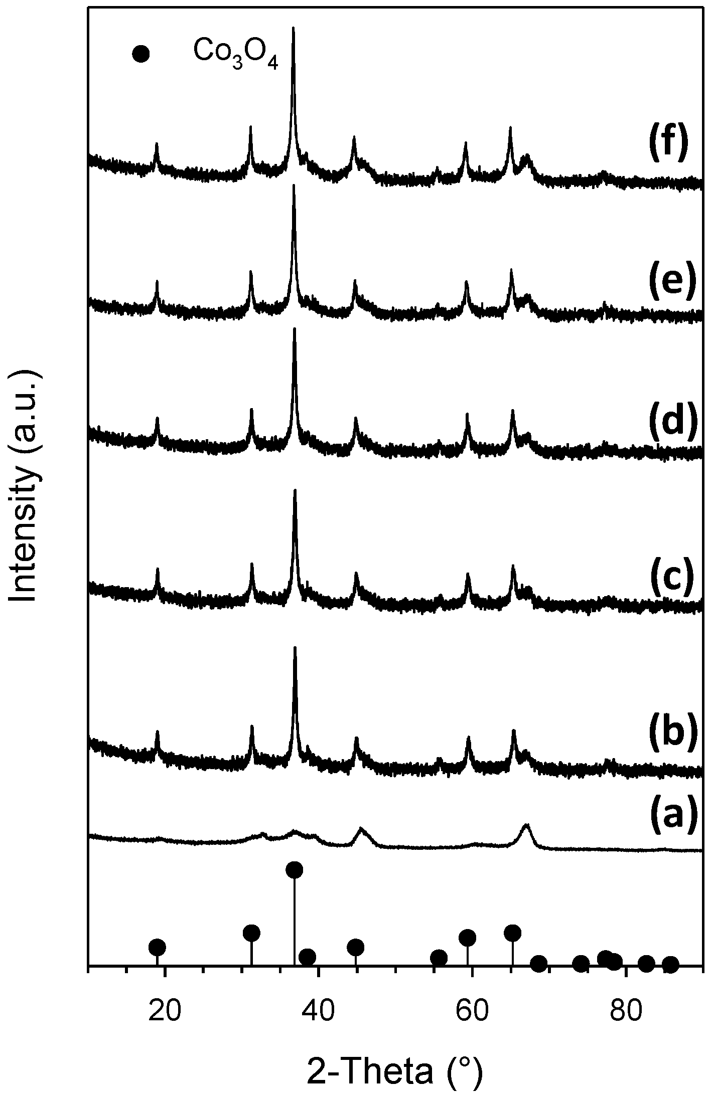
2.1. Catalyst Characterization
2.2. Cobalt Reducibility
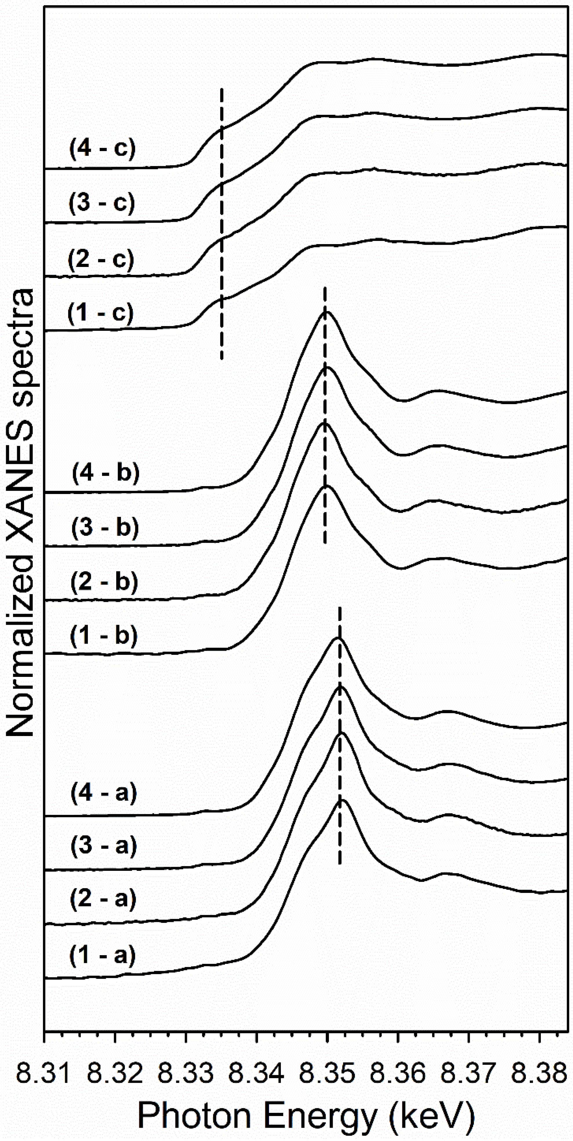
2.2.1. H2 TPR-XANES
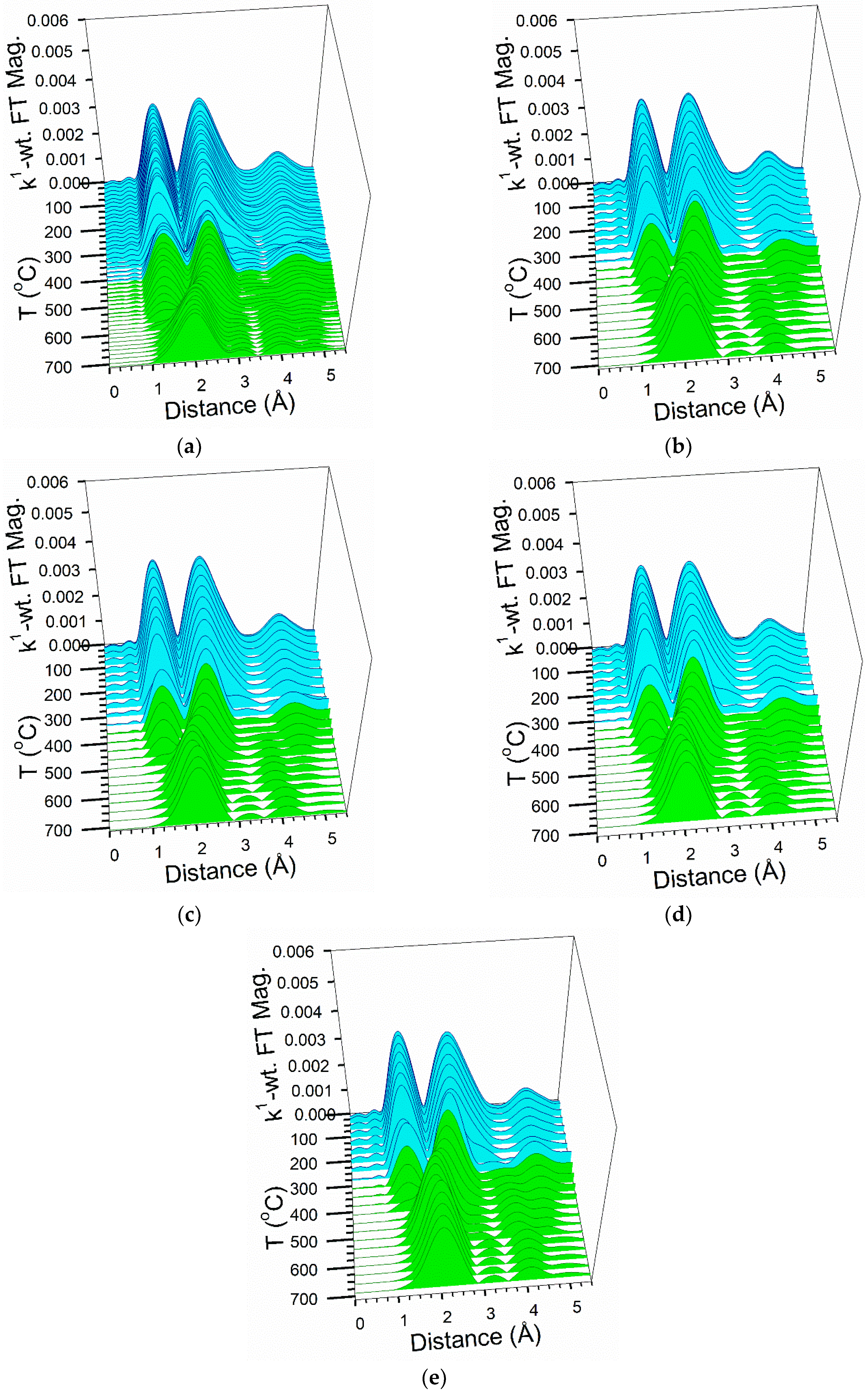
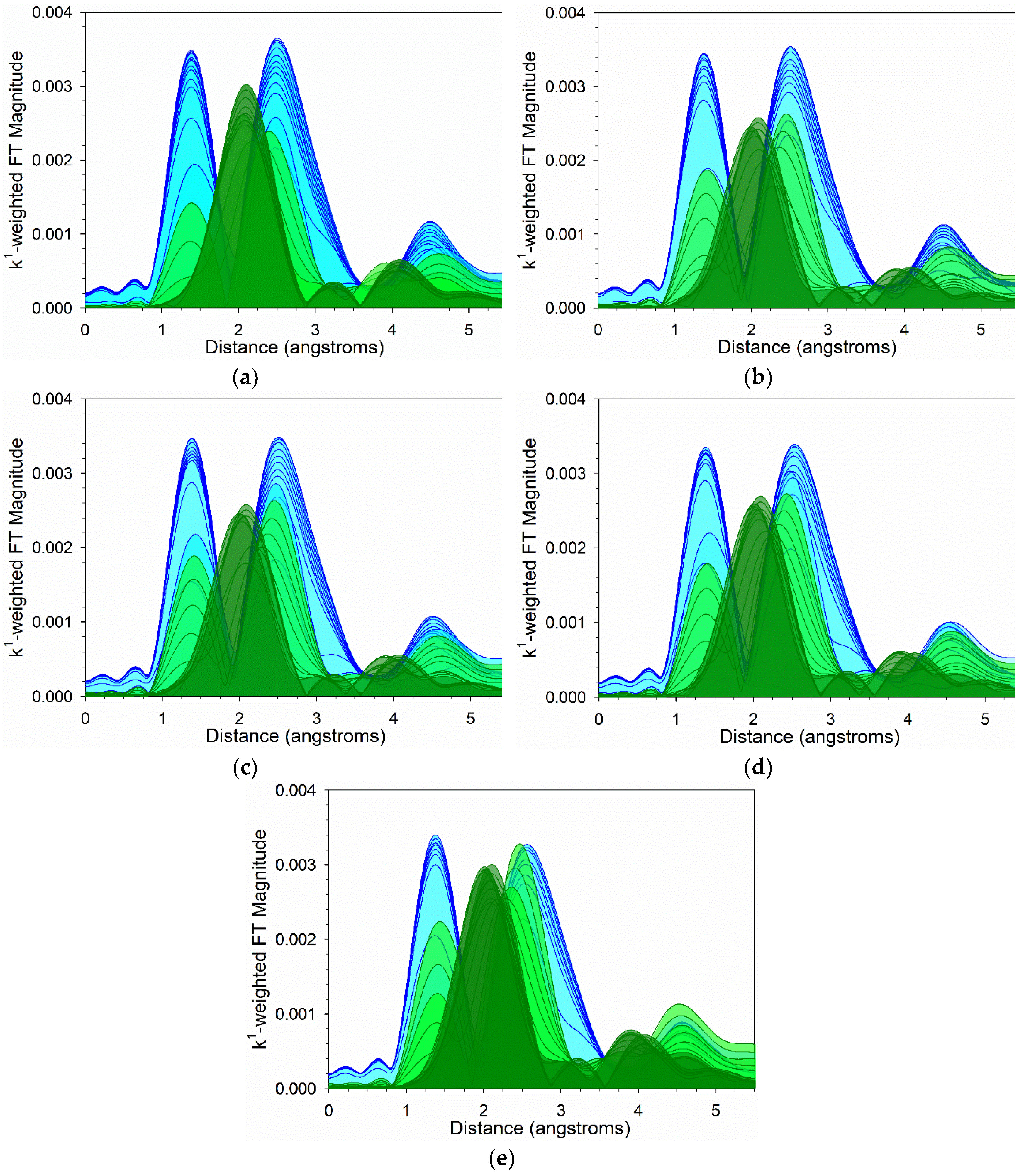
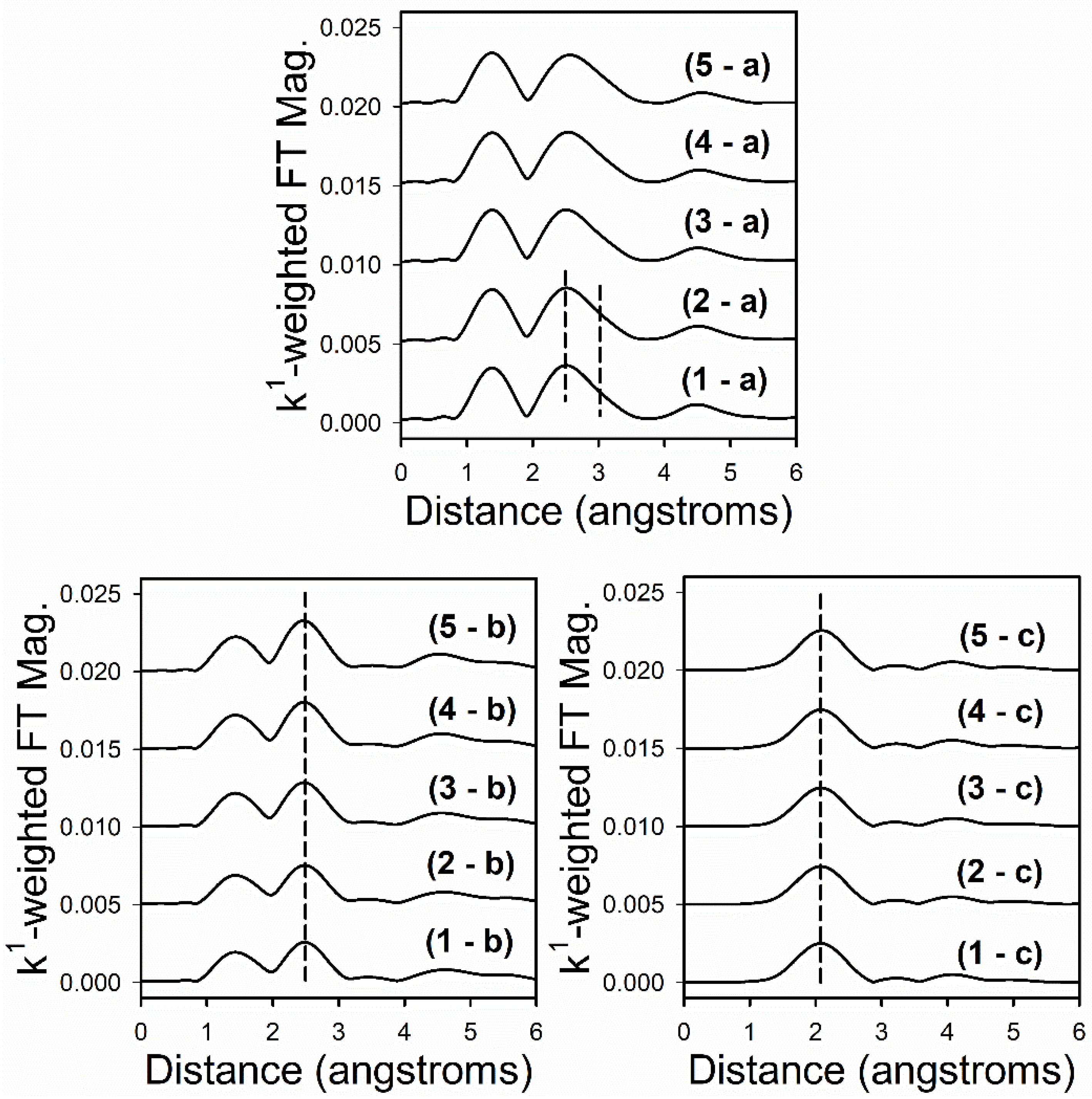
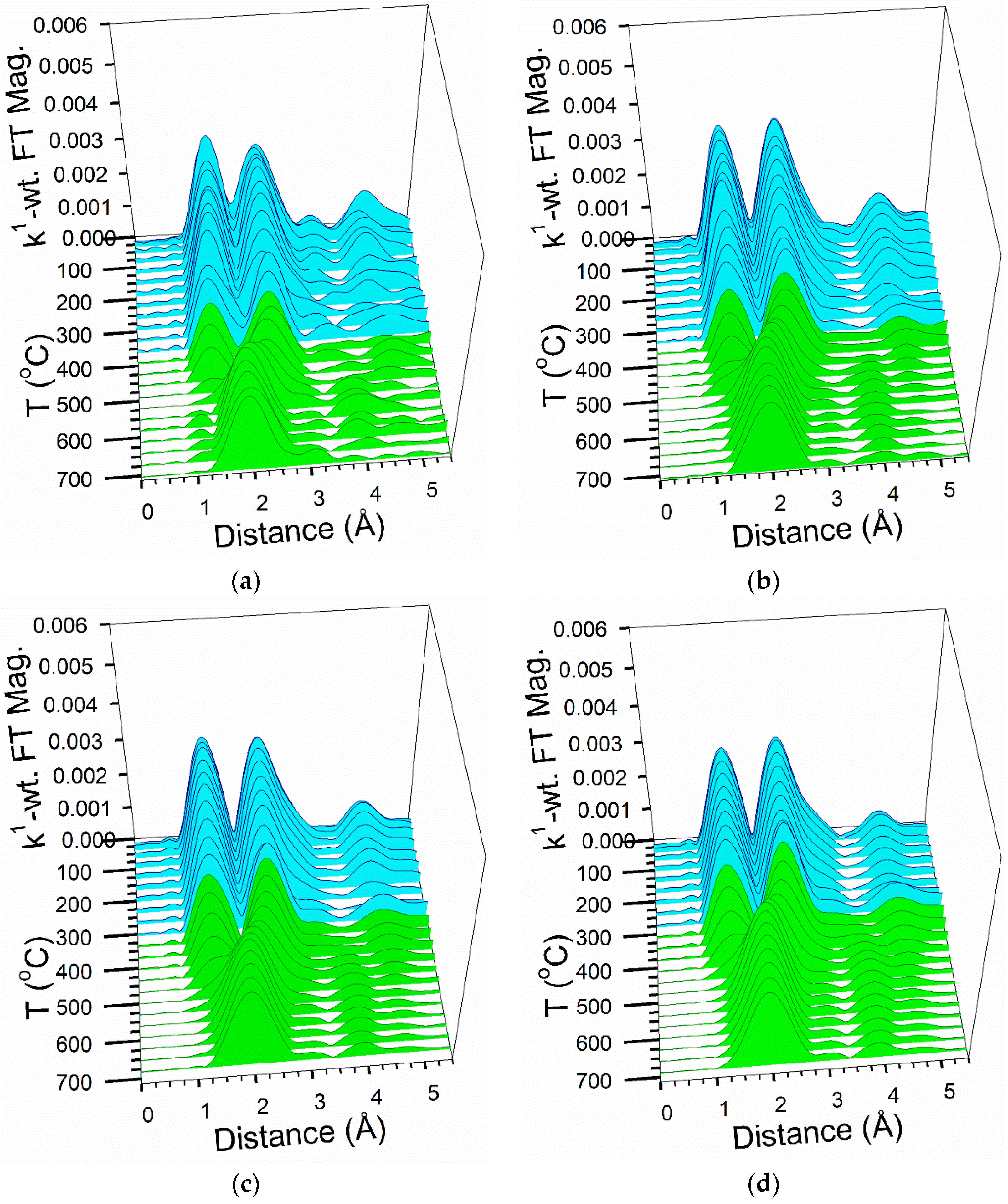
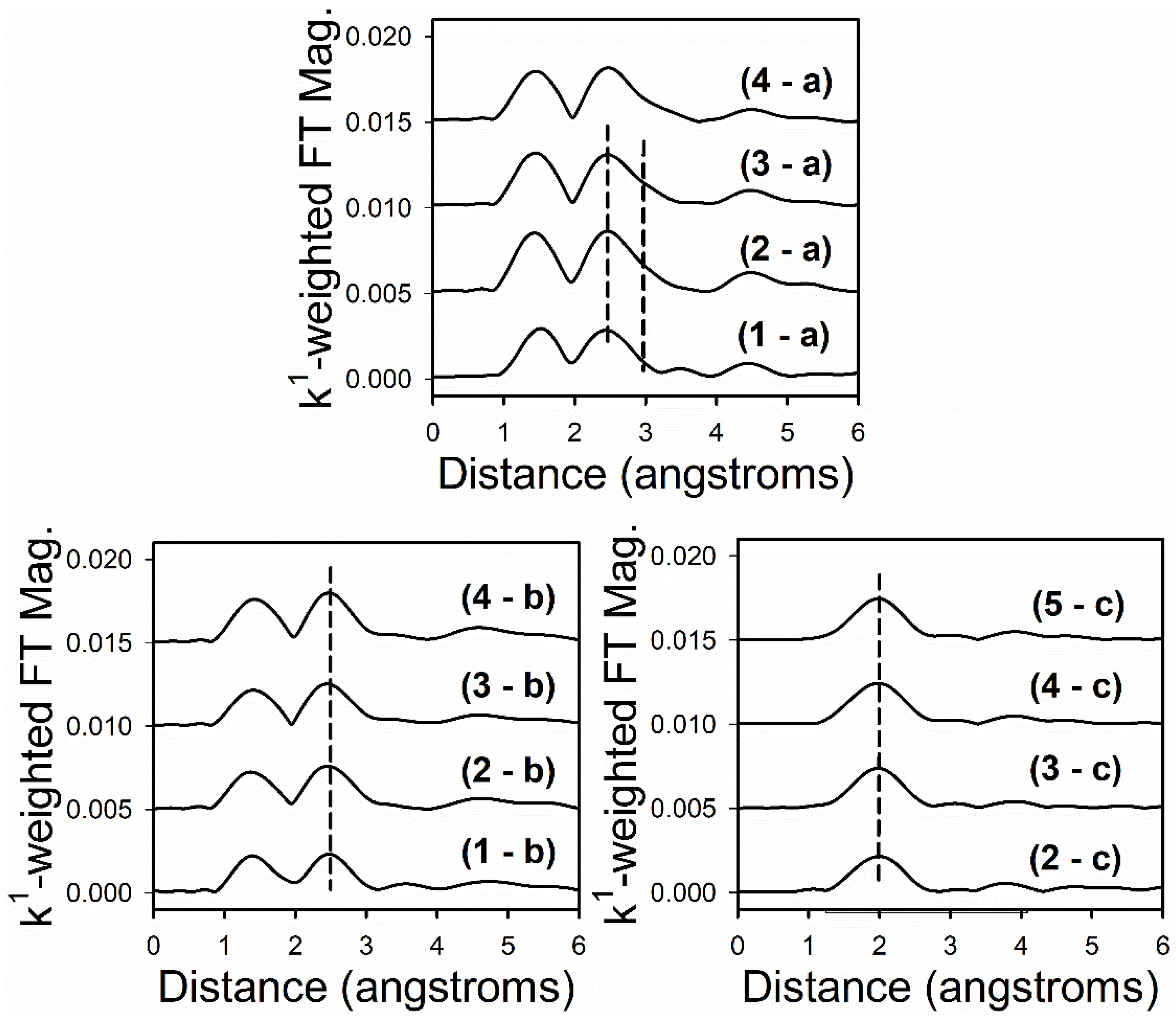
2.2.2. H2 TPR-EXAFS
2.3. Nickel Reducibility
2.3.1. H2 TPR-XANES
2.3.2. H2 TPR-EXAFS
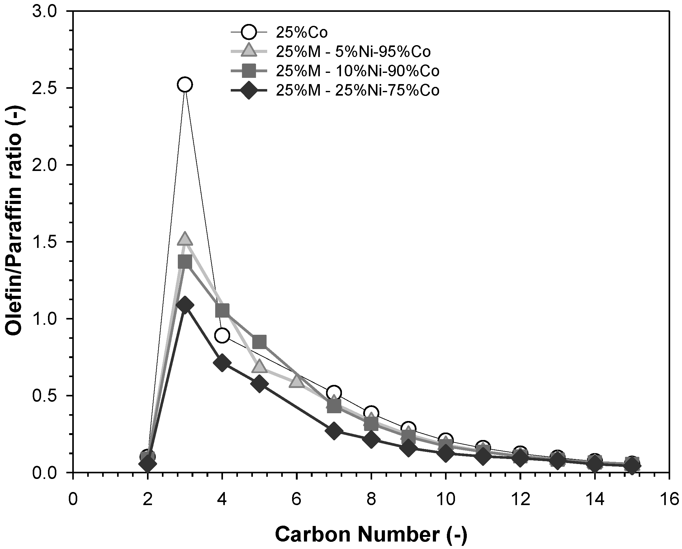
2.4. Catalytic Activity
3. Discussion
4. Materials and Methods
4.1. Catalyst Preparation
4.2. Characterization
- % Dispersion (uncorrected) = (# metal atoms on the surface)/(# metal atoms in the sample)
- % Disp. (corrected) = (# metal atoms on the surface)/((# metal atoms in the sample)(% reduction))
4.3. H2-TPR XANES-EXAFS
4.4. Reaction Testing
5. Conclusions
Author Contributions
Funding
Acknowledgments
Conflicts of Interest
References
- Schulz, H. Short history and present trends of Fischer–Tropsch synthesis. Appl. Catal. A Gen. 1999, 186, 3–12. [Google Scholar] [CrossRef]
- Shafer, W.D.; Gnanamani, M.K.; Graham, U.M.; Yang, J.; Masuku, C.M.; Jacobs, G.; Davis, B.H. Fischer–Tropsch: Product selectivity–The fingerprint of synthetic fuels. Catalysts 2019, 9, 259. [Google Scholar] [CrossRef] [Green Version]
- Khodakov, A.Y.; Chu, W.; Fongarland, P. Advances in the development of novel cobalt Fischer−Tropsch catalysts for synthesis of long-chain hydrocarbons and clean fuels. Chem. Rev. 2007, 107, 1692–1744. [Google Scholar] [CrossRef] [PubMed]
- Jahangiri, H.; Bennett, J.; Mahjoubi, P.; Wilson, K.; Gu, S. A review of advanced catalyst development for Fischer–Tropsch synthesis of hydrocarbons from biomass derived syn-gas. Catal. Sci. Technol. 2014, 4, 2210–2229. [Google Scholar] [CrossRef] [Green Version]
- Glacier, I. Resource Management Group. Available online: http://www.infomine.com/investment (accessed on 20 December 2019).
- Iglesia, E. Design, synthesis, and use of cobalt-based Fischer-Tropsch synthesis catalysts. Appl. Catal. A Gen. 1997, 161, 59–78. [Google Scholar] [CrossRef]
- Hou, C.; Xia, G.; Sun, X.; Wu, Y.; Jin, C.; Yan, Z.; Li, M.; Hu, Z.; Nie, H.; Li, D. Thermodynamics of oxidation of an alumina-supported cobalt catalyst by water in F-T synthesis. Catal. Today 2016, 264, 91–97. [Google Scholar] [CrossRef]
- Van Steen, E.; Claeys, M.; Dry, M.E.; Van de Loosdrecht, J.; Viljoen, E.L.; Visagie, J.L. Stability of nanocrystals: Thermodynamic analysis of oxidation and re-reduction of cobalt in water/hydrogen mixtures. J. Phys. Chem. B 2005, 109, 3575–3577. [Google Scholar] [CrossRef]
- Jacobs, G.; Patterson, P.M.; Das, T.K.; Luo, M.; Davis, B.H. Fischer–Tropsch synthesis: Effect of water on Co/Al2O3 catalysts and XAFS characterization of reoxidation phenomena. Appl. Catal. A Gen. 2004, 270, 65–76. [Google Scholar] [CrossRef]
- Van Helden, P.; Prinsloo, F.; Van den Berg, J.-A.; Xaba, B.; Erasmus, W.; Claeys, M.; Van de Loosdrecht, J. Cobalt-nickel bimetallic Fischer-Tropsch catalysts: A combined theoretical and experimental approach. Catal. Today 2020, 342, 88–98. [Google Scholar] [CrossRef]
- Shadravan, V.; Bukas, V.J.; Gunasooriya, G.T.K.K.; Waleson, J.; Drewery, M.; Karibika, J.; Jones, J.; Kennedy, E.; Adesina, A.; Nørskov, J.K.; et al. Effect of manganese on the selective catalytic hydrogenation of COx in the presence of light hydrocarbons over Ni/Al2O3: An experimental and computational study. ACS Catal. 2020, 10, 1535–1547. [Google Scholar] [CrossRef] [Green Version]
- Ishihara, T.; Horiuchi, N.; Inoue, T.; Eguchi, K.; Takita, Y.; Arai, H. Effect of alloying on CO hydrogenation activity over SiO2-supported Co-Ni alloy catalysts. J. Catal. 1992, 136, 232–241. [Google Scholar] [CrossRef]
- Ishihara, T.; Iwakuni, H.; Eguchi, K.; Arai, H. Hydrogenation of carbon monoxide over the mixed catalysts composed of cobalt-nickel/manganese oxide-zirconium oxide and zeolite catalysts. Appl. Catal. 1991, 75, 225–235. [Google Scholar] [CrossRef]
- Ishihara, T.; Eguchi, K.; Arai, H. Hydrogenation of carbon monoxide over SiO2-supported Fe-Co, Co-Ni and Ni-Fe bimetallic catalysts. Appl. Catal. 1987, 30, 225–238. [Google Scholar] [CrossRef]
- Sun, Y.; Wei, J.; Zhang, J.P.; Yang, G. Optimization using response surface methodology and kinetic study of Fischer–Tropsch synthesis using SiO2 supported bimetallic Co–Ni catalyst. J. Nat. Gas Sci. Eng. 2016, 28, 173–183. [Google Scholar] [CrossRef]
- Shimura, K.; Miyazawa, T.; Hanaoka, T.; Hirata, S. Fischer–Tropsch synthesis over alumina supported bimetallic Co–Ni catalyst: Effect of impregnation sequence and solution. J. Mol. Catal. A Chem. 2015, 407, 15–24. [Google Scholar] [CrossRef]
- Eshraghi, A.; Mirzaei, A.A.; Rahimi, R.; Atashi, H. Effect of Ni–Co morphology on kinetics for Fischer–Tropsch reaction in a fixed-bed reactor. J. Taiwan Inst. Chem. Eng. 2019, 105, 104–114. [Google Scholar] [CrossRef]
- Rytter, E.; Skagseth, T.H.; Eri, S.; Sjåstad, A.O. Cobalt Fischer−Tropsch catalysts using nickel promoter as a rhenium substitute to suppress deactivation. Ind. Eng. Chem. Res. 2010, 49, 4140–4148. [Google Scholar] [CrossRef]
- Voss, G.J.B.; Fløystad, J.B.; Voronov, A.; Rønning, M. The state of nickel as promotor in cobalt Fischer–Tropsch synthesis catalysts. Top. Catal. 2015, 58, 896–904. [Google Scholar] [CrossRef]
- López-Tinoco, J.; Mendoza-Cruz, R.; Bazán-Díaz, L.; Karuturi, S.C.; Martinelli, M.; Cronauer, D.C.; Kropf, A.J.; Marshall, C.L.; Jacobs, G. The preparation and characterization of Co–Ni nanoparticles and the testing of a heterogenized Co–Ni/alumina catalyst for CO hydrogenation. Catalysts 2019, 10, 18. [Google Scholar] [CrossRef] [Green Version]
- Nikparsa, P.; Mirzaei, A.A.; Rauch, R. Modification of Co/Al2O3 Fischer–Tropsch nanocatalysts by adding Ni: A kinetic approach. Int. J. Chem. Kinet. 2016, 48, 131–143. [Google Scholar] [CrossRef]
- Yu, H.; Zhao, A.; Zhang, H.; Ying, W.; Fang, D. Bimetallic catalyst of Co and Ni for Fischer-Tropsch synthesis supported on alumina, energy sources. Part A Recovery Util. Environ. Eff. 2015, 37, 47–54. [Google Scholar]
- Jacobs, G.; Ma, W.; Gao, P.; Todic, B.; Bhatelia, T.; Bukur, D.B.; Davis, B.H. The application of synchrotron methods in characterizing iron and cobalt Fischer–Tropsch synthesis catalysts. Catal. Today 2013, 214, 100–139. [Google Scholar] [CrossRef]
- Van Der Laan, G.P.; Beenackers, A.A.C.M. Kinetics and selectivity of the Fischer–Tropsch synthesis: A literature review. Catal. Rev. 1999, 41, 255–318. [Google Scholar] [CrossRef]
- Tsakoumis, N.E.; Rønning, M.; Borg, Ø.; Rytter, E.; Holmen, A. Deactivation of cobalt based Fischer–Tropsch catalysts: A review. Catal. Today 2010, 154, 162–182. [Google Scholar] [CrossRef]
- Jacobs, G.; Patterson, P.M.; Zhang, Y.; Das, T.; Li, J.; Davis, B.H. Fischer–Tropsch synthesis: Deactivation of noble metal-promoted Co/Al2O3 catalysts. Appl. Catal. A Gen. 2002, 233, 215–226. [Google Scholar] [CrossRef]
- Jacoby, M. X-ray absorption spectroscopy. Chem. Eng. News Arch. 2001, 79, 33–38. [Google Scholar] [CrossRef]
- Ressler, T. WinXAS: A program for X-ray absorption spectroscopy data analysis under MS-Windows. J. Synchrotron Radiat. 1998, 5, 118–122. [Google Scholar] [CrossRef]
- Jacobs, G.; Ji, Y.; Davis, B.H.; Cronauer, D.; Kropf, A.J.; Marshall, C.L. Fischer–Tropsch synthesis: Temperature programmed EXAFS/XANES investigation of the influence of support type, cobalt loading, and noble metal promoter addition to the reduction behavior of cobalt oxide particles. Appl. Catal. A Gen. 2007, 333, 177–191. [Google Scholar] [CrossRef]
- Ravel, B. ATOMS: Crystallography for the X-ray absorption spectroscopist. J. Synchrotron Radiat. 2001, 8, 314–316. [Google Scholar] [CrossRef] [Green Version]
- Newville, M.; Ravel, B.; Haskel, D.; Rehr, J.J.; Stern, E.A.; Yacoby, Y. Analysis of multiple-scattering XAFS data using theoretical standards. Phys. B Condens. Matter 1995, 208–209, 154–156. [Google Scholar] [CrossRef]
- Jacobs, G.; Ribeiro, M.C.; Ma, W.; Ji, Y.; Khalid, S.; Sumodjo, P.T.A.; Davis, B.H. Group 11 (Cu, Ag, Au) promotion of 15%Co/Al2O3 Fischer–Tropsch synthesis catalysts. Appl. Catal. A Gen. 2009, 361, 137–151. [Google Scholar] [CrossRef]


| Sample ID | As (BET) [m2/g] | Vp (BJH Des) [cm3/g] | Dp (BJH Des) [Å] | Co% | Ni% |
|---|---|---|---|---|---|
| 25%Co | 95.5 | 0.243 | 93 | 30.21 | - |
| 25%M—5%Ni-95%Co | 92.9 | 0.226 | 91 | 30.49 | 1.43 |
| 25%M—10%Ni-90%Co | 96.5 | 0.227 | 94 | 31.58 | 2.97 |
| 25%M—25%Ni-75%Co | 96.0 | 0.236 | 89 | 24.86 | 7.7 |
| 25%M—50%Ni-50%Co | 91.6 | 0.237 | 87 | 17.4 | 16.2 |
| µmol H2 desorbed/gcat | Uncorr. % Disp. | Uncorr. Diam. (nm) | O2 Uptake (mol/gcat) | * % Red. | ** % Red. | * Corr. % Disp. | ** Corr. % Disp. | * Corr. Diam. (nm) | ** Corr. Diam. (nm) |
|---|---|---|---|---|---|---|---|---|---|
| 25%Co/Al2O3 | |||||||||
| 91.3 | 4.3 | 24 | 1324 | 46.8 | 29.1 | 9.2 | 14.8 | 11.2 | 7.0 |
| 25%M (95%Co-5%Ni)/Al2O3 | |||||||||
| 104.0 | 4.9 | 21.1 | 1317 | 47.3 | 30.4 | 10.4 | 16.1 | 10.0 | 6.4 |
| 25%M (90%Co-10%Ni)/Al2O3 | |||||||||
| 92.5 | 4.4 | 24 | 1495 | 54.6 | 40.5 | 8.0 | 10.8 | 12.9 | 9.6 |
| 25%M (75%Co-25%Ni)/Al2O3 | |||||||||
| 94.6 | 4.5 | 23.2 | 1563 | 59.9 | 48.7 | 7.5 | 9.2 | 13.9 | 11.3 |
| 25%M (50%Co-50%Ni)/Al2O3 | |||||||||
| 94.7 | 4.5 | 23.1 | 1594 | 65.7 | 58.5 | 6.8 | 7.6 | 15.2 | 13.5 |
| Sample Description | N Co–Co Metal | R Co–Co (Å) Metal | N Co-Ni Metal | R Co-Ni (Å) Metal | N Ni-Ni Metal | R Ni-Ni (Å) Metal | N Ni-Co Metal | R Ni-Co (Å) Metal | e0 (eV) | σ2 (Å2) | r-factor |
|---|---|---|---|---|---|---|---|---|---|---|---|
| 100Co | 9.9 | 2.489 (0.003) | - | - | - | - | - | - | 6.37 (0.45) | 0.00731 (0.00043) | 0.0010 |
| 5Ni:95Co | 9.9 (0.78) | 2.489 (0.0053) | 0.50 (0.04) | 2.481 (0.0053) | 0.32 (0.03) | 2.472 (0.0053) | 6.3 (0.59) | 2.481 (0.0053) | 6.32 (0.813) | 0.00787 (0.00076) | 0.014 |
| 10Ni:90Co | 9.4 (0.48) | 2.492 (0.0034) | 0.94 (0.05) | 2.483 (0.0034) | 0.75 (0.04) | 2.475 (0.0034) | 7.5 (0.41) | 2.483 (0.0034) | 6.56 (0.527) | 0.00777 (0.00048) | 0.0035 |
| 25Ni:75Co | 8.0 (0.31) | 2.491 (0.0026) | 2.0 (0.08) | 2.482 (0.0026) | 1.9 (0.08) | 2.474 (0.0026) | 7.4 (0.32) | 2.482 (0.0026) | 6.71 (0.401) | 0.00719 (0.00036) | 0.0023 |
| 50Ni:50Co | 6.5 (0.36) | 2.491 (0.0035) | 3.3 (0.18) | 2.483 (0.0035) | 3.2 (0.18) | 2.475 (0.0035) | 6.4 (0.36) | 2.483 (0.0035) | −4.39 (0.613) | 0.00659 (0.00049) | 0.0034 |
| Sample ID | Activity/$ |
|---|---|
| 25%Co | 39.5 |
| 25%M—5%Ni-95%Co | 35.4 |
| 25%M—10%Ni-90%Co | 36.8 |
| 25%M—25%Ni-75%Co | 41.9 |
© 2020 by the authors. Licensee MDPI, Basel, Switzerland. This article is an open access article distributed under the terms and conditions of the Creative Commons Attribution (CC BY) license (http://creativecommons.org/licenses/by/4.0/).
Share and Cite
Martinelli, M.; Karuturi, S.C.; Garcia, R.; Watson, C.D.; Shafer, W.D.; Cronauer, D.C.; Kropf, A.J.; Marshall, C.L.; Jacobs, G. Substitution of Co with Ni in Co/Al2O3 Catalysts for Fischer–Tropsch Synthesis. Catalysts 2020, 10, 334. https://doi.org/10.3390/catal10030334
Martinelli M, Karuturi SC, Garcia R, Watson CD, Shafer WD, Cronauer DC, Kropf AJ, Marshall CL, Jacobs G. Substitution of Co with Ni in Co/Al2O3 Catalysts for Fischer–Tropsch Synthesis. Catalysts. 2020; 10(3):334. https://doi.org/10.3390/catal10030334
Chicago/Turabian StyleMartinelli, Michela, Sai Charan Karuturi, Richard Garcia, Caleb D. Watson, Wilson D. Shafer, Donald C. Cronauer, A. Jeremy Kropf, Christopher L. Marshall, and Gary Jacobs. 2020. "Substitution of Co with Ni in Co/Al2O3 Catalysts for Fischer–Tropsch Synthesis" Catalysts 10, no. 3: 334. https://doi.org/10.3390/catal10030334