Article

Parametric Analysis and Optimization of Radially Layered Cylindrical Piezoceramic/Epoxy Composite Transducers

1
Department of Applied Mechanics, University of Science and Technology Beijing, Beijing 100083, China
2
Beijing Key Laboratory for Sensors, Beijing Information Science & Technology University, Beijing 100101, China
3
School of Civil and Environmental Engineering, Harbin Institute of Technology, Shenzhen 518055, China
4
Department of Mechanics, Beijing Jiaotong University, Beijing 100044, China
*
Author to whom correspondence should be addressed.
Micromachines 2018, 9(11), 585; https://doi.org/10.3390/mi9110585
Submission received: 8 October 2018 / Revised: 28 October 2018 / Accepted: 6 November 2018 / Published: 9 November 2018
(This article belongs to the Special Issue Piezoelectric Transducers: Materials, Devices and Applications)

Abstract

:
Radially layered cylindrical piezoceramic/epoxy composite transducers have been designed by integrating the excellent performance of piezoelectric/polymer composites and the radial radiation ability of cylindrical configurations, which are promising in developing novel ultrasonic and underwater sound techniques. Our previous study has explored the effects of the external resistance on the electromechanical characteristics of the transducer, and obtained some valuable findings. To clearly understand the electromechanical characteristics of the transducer and to guide the device design, in this paper, parametric analysis was performed to reveal the effects of multiple key factors on the electromechanical characteristics. These factors include material parameters of epoxy layers, piezoceramic material types, and locations of piezoceramic rings. In order to better analyze the influence of these factors, a modified theoretical model, in which every layer has different geometric and material parameters, was developed based on the model given in the previous work. Furthermore, the reliability of the model was validated by the ANSYS simulation results and the experimental results. The present investigation provides some helpful guidelines to design and optimize the radially layered cylindrical piezoceramic/epoxy composite transducers.

1. Introduction

Piezoelectric ultrasonic and underwater sound transducers, by virtue of their excellent electromechanical properties, have been widely applied in medical imaging [1,2,3], non-destructive testing [4,5], underwater communications [6,7], and so on. In recent years, researchers have been trying to improve their design in hope of obtaining more excellent abilities to perform related tasks. Many attempts have been made and this research topic has received more and more attention.
One effective attempt is to add a flexible polymer phase when fabricating the piezoelectric/polymer composites. These composites can overcome the shortcomings of single-phase piezoelectric materials, such as brittleness, high acoustic impedance, and at the same time possess the advantages of both the piezoceramics and the polymers, including low acoustic impedance, high electromechanical coupling coefficient, low mechanical loss and large dielectric constant [8,9]. Through designing and optimizing various connectivity patterns, such as 1-3 type [10,11,12,13,14,15,16,17,18], 2-2 type [3,19,20,21], these transducers can be used in high-frequency, high-power, and high-temperature applications [9]. In addition, an addition of modified epoxy, i.e., aluminum load epoxy, can also enhance their dielectric, piezoelectric and acoustic dampening [22,23,24], which is very useful for structural health monitoring, energy harvesting, and acoustic liners [22].
Another approach is to adopt new structural forms to realize multiple functionalities. The earlier transducers mainly adopted the approximated one-dimensional structures, which can excite one-dimensional longitudinal waves. The representative devices are the longitudinally sandwiched transducers [25,26,27,28,29] that are composed of axially polarized piezoceramic rings and end metal masses. Recently, two dimensional structures, i.e., cylindrical configurations, were proposed to increase the wave coverage area and output power. These structures include tubes, shells, disks and rings [30,31,32,33,34,35,36,37,38,39,40,41,42,43,44,45,46,47]. They can realize the radial wave radiations by utilizing their radial vibrations, and can be used as the omni-directional emitter and receiver in underwater sound and ultrasonic applications [48].
The above two methods can improve the performance of piezoelectric transducers to meet different requirements. However, both of these methods have certain limitations. In addition, in some special applications, such as endoscopic ultrasound (EUS), it is required that the transducer is able to realize 360° imaging [49]. To obtain a comprehensive performance, some efforts have been made to focus on combining the advantages of piezoelectric/polymer composites and those of cylindrical configurations. One attempt was adopting the 1-3 type piezocomposite to design the cylindrical EUS transducers, which can acquire high-resolution EUS imaging [50]. Another attempt was using the 2-2 type piezocomposite to develop the cylindrical underwater acoustic transducers, which can achieve high-frequency wideband ability [51]. In the latest work, a new type of radially layered cylindrical piezoceramic/epoxy composite transducer was developed by integrating two concentric axially polarized piezoceramic rings into cylindrical epoxy matrixes, which is expected to be utilized in developing novel ultrasonic and underwater sound techniques [52]. This preliminary study mainly focused on studying the effects of the external resistance on the electromechanical characteristics of the transducer, which lacked of clear understanding on the influences of other key factors, including material parameters of epoxy layers, piezoceramic material types, and locations of piezoceramic rings. To clearly understand the electromechanical characteristics of this type of transducer and to guide the device design, in this paper, parametric analysis was performed to reveal the effects of these multiple key factors on the electromechanical characteristics of the transducer.
The remainder of this paper is organized as follows. Section 2 exhibits a schematic representation of the radially layered cylindrical piezoceramic/epoxy composite transducer and gives its modified theoretical model based on the model developed in previous work. Section 3 validates the theoretical solution by comparing it to solutions from both ANSYS numerical simulation and experimental investigation. Section 4 discusses the effects of material parameters of epoxy layers, piezoceramic material types, and locations of piezoceramic rings on the electromechanical characteristics of the transducer through numerical analysis. Section 5 draws the conclusions of the paper.

2. Modeling

2.1. Basic Equations

Figure 1 exhibits the schematic representation of the radially layered cylindrical piezoceramic/epoxy composite transducer. It consists of a solid epoxy disk, two epoxy rings, and two axially polarized piezoceramic rings. These components are arranged alternatively in the radial direction. The two piezoceramic rings are connected in parallel electrically, and are denoted as piezoceramic ring #1 and piezoceramic ring #2, respectively. Three epoxy layers are denoted as epoxy disk #1, epoxy ring #2 and epoxy ring #3, respectively. The geometric and material parameters of each layer are different. The radial location of the interface between each layer and the axial height of the transducer are defined as R i   ( i = 1 , 2 , 3 , 4 , 5 ) and h , respectively.
A harmonic form of voltage is used as the excitation source, which is expressed as:
V ( t ) = V 0 e j ω t ,
where V 0 , j = 1 , ω = 2 π f , f and t are the excitation amplitude, the imaginary unit, the circular frequency, the excitation frequency and the time, respectively.
Under the assumption of plane stress, the harmonic radial displacement u r P ( i ) , radial stress σ r P ( i ) , electric potential ϕ ( i ) and electric displacement D z ( i ) of the i-th piezoelectric layer (i = 1, 2) are expressed as follows [52,53]:
u r P ( i ) = [ A P ( i ) f 1 ( r , i ) + B P ( i ) f 2 ( r , i ) ] e j ω t ,
σ r P ( i ) = [ A P ( i ) f 3 ( r , i ) + B P ( i ) f 4 ( r , i ) + e 31 ( i ) ( V 0 / h ) ] e j ω t ,
ϕ ( i ) = z ( V 0 / h ) e j ω t ,
D z ( i ) ( z ) = [ A P ( i ) e 31 ( i ) k P ( i ) J 0 ( k P ( i ) r ) + B P ( i ) e 31 ( i ) k P ( i ) Y 0 ( k P ( i ) r ) κ 33 ( i ) ε ( V 0 / h ) ] e j ω t ,
In Equations (2)–(5), the functions from f1(r,i) to f4(r,i) can be expressed as following [52,53]:
f 1 ( r , i ) = J 1 ( k P ( i ) r ) ,
f 2 ( r , i ) = Y 1 ( k P ( i ) r ) ,
f 3 ( r , i ) = c 11 ( i ) E k P ( i ) J 0 ( k P ( i ) r ) + [ ( c 12 ( i ) E c 11 ( i ) E ) / r ] J 1 ( k P ( i ) r ) ,
f 4 ( r , i ) = c 11 ( i ) E k P ( i ) Y 0 ( k P ( i ) r ) + [ ( c 12 ( i ) E c 11 ( i ) E ) / r ] Y 1 ( k P ( i ) r ) ,
where c 11 ( i ) E = s 11 ( i ) E / ( s 11 ( i ) E s 11 ( i ) E s 12 ( i ) E s 12 ( i ) E ) , c 12 ( i ) E = s 12 ( i ) E / ( s 11 ( i ) E s 11 ( i ) E s 12 ( i ) E s 12 ( i ) E ) , e 31 ( i ) = d 31 ( i ) / ( s 11 ( i ) E + s 12 ( i ) E ) , κ 33 ( i ) ε = κ 33 ( i ) σ 2 d 31 ( i ) 2 / ( s 11 ( i ) E + s 12 ( i ) E ) ; c 11 ( i ) E , c 12 ( i ) E , e 31 ( i ) , and κ 33 ( i ) ε are the effective elastic, piezoelectric and dielectric constants of the i-th piezoceramic layer, respectively. k P ( i ) = ω / V r P ( i ) and V r P ( i ) = c 11 ( i ) E / ρ P ( i ) are the radial wave number and sound speed, respectively; ρ P ( i ) is the density of the piezoceramic. J 0 ( k P ( i ) r ) is the Bessel function of the first kind, and Y 0 ( k P ( i ) r ) is the Bessel function of the second kind.
Similarly, the harmonic radial displacement u r E ( i ) and radial stress σ r E ( i ) of the i-th elastic layers (i = 1, 2, 3) are expressed as follows [52,53,54]:
u r E ( i ) ( r ) = [ A E ( i ) f 5 ( r , i ) + B E ( i ) f 6 ( r , i ) ] e j ω t ,
σ r E ( i ) ( r ) = [ A E ( i ) f 7 ( r , i ) + B E ( i ) f 8 ( r , i ) ] e j ω t .
In Equations (10) and (11), the functions from f5(r,i) to f8(r,i) can be expressed as following [52,53,54]:
f 5 ( r , i ) = J 1 ( k E ( i ) r ) ,
f 6 ( r , i ) = Y 1 ( k E ( i ) r ) ,
f 7 ( r , i ) = [ ( E ¯ ( i ) k E ( i ) ) / ( 1 μ ( i ) 2 ) ] { J 0 ( k E ( i ) r ) + [ ( μ ( i ) 1 ) / ( k E ( i ) r ) ] J 1 ( k E ( i ) r ) } ,
f 8 ( r , i ) = [ ( E ¯ ( i ) k E ( i ) ) / ( 1 μ ( i ) 2 ) ] { Y 0 ( k E ( i ) r ) + [ ( μ ( i ) 1 ) / ( k E ( i ) r ) ] Y 1 ( k E ( i ) r ) } ,
where k E ( i ) = ω / V r E ( i ) , V r E ( i ) 2 = E ¯ ( i ) / [ ρ E ( i ) ( 1 μ ( i ) 2 ) ] ; ρ E ( i ) , E ¯ ( i ) and μ ( i ) are the density, Young’s modulus and Poisson’s ratio of epoxy, respectively.

2.2. Solution

As shown in Figure 1, the boundary and continuity conditions of the cylindrical transducer consist of one innermost displacement boundary condition, one outermost stress boundary condition and eight continuous conditions, which are given as follows:
{ u r E ( 1 ) | r = 0 = 0 σ r E ( 3 ) | r = R 5 = 0 ,
{ u r P ( i ) | r = R 2 i 1 = u r E ( i ) | r = R 2 i 1 σ r P ( i ) | r = R 2 i 1 = σ r E ( i ) | r = R 2 i 1   ( i = 1 ,   2 ) ,
{ u r P ( i ) | r = R 2 i = u r E ( i + 1 ) | r = R 2 i σ r P ( i ) | r = R 2 i = σ r E ( i + 1 ) | r = R 2 i ( i = 1 ,   2 ) ,
Combining Equations (2), (3), (10), (11), and (16)–(18), 10 coefficients can be derived, which are listed in Equations (A1)–(A5) (Appendix A). Further, the total electrical charge Q t o t a l ( t ) and the total current I t o t a l ( t ) can be expressed by the following expressions:
Q t o t a l ( t ) = Q ( 1 ) ( t ) + Q ( 2 ) ( t ) = 0 2 π R 1 R 2 D z ( 1 ) r d θ d r + 0 2 π R 3 R 4 D z ( 2 ) r d θ d r = ( C ˜ 1 + C ˜ 2 ) V 0 e j ω t ,
I t o t a l ( t ) = d Q t o t a l ( t ) / d t = j ω ( C ˜ 1 + C ˜ 2 ) V 0 e j ω t ,
where
C ˜ 1 = 2 π { ( a 1 v 9 + v 1 ) [ f 9 ( R 2 , 1 ) f 9 ( R 1 , 1 ) ] + ( a 2 v 9 + v 2 ) [ f 10 ( R 2 , 1 ) f 10 ( R 1 , 1 ) ] } C 1 ,
C ˜ 2 = 2 π { ( a 5 v 9 + v 5 ) [ f 9 ( R 4 , 2 ) f 9 ( R 3 , 2 ) ] + ( a 6 v 9 + v 6 ) [ f 10 ( R 4 , 2 ) f 10 ( R 3 , 2 ) ] } C 2 ,
f 9 ( r , i ) = e 31 ( i ) r J 1 ( k P ( i ) r ) ( i = 1 , 2 ) ,
f 10 ( r , i ) = e 31 ( i ) r Y 1 ( k P ( i ) r ) ( i = 1 , 2 ) ,
In Equations (23) and (24), C 1 = π ( κ 33 ( 1 ) ε / h ) ( R 2 2 R 1 2 ) and C 2 = π ( κ 33 ( 2 ) ε / h ) ( R 4 2 R 3 2 ) are the clamped electric capacitances of piezoceramic rings #1 and #2 in radial vibration, respectively. C ˜ 1 and C ˜ 2 are the effective electric capacitances of piezoceramic rings #1 and #2 in radial vibration, respectively. Then, the electrical impedance of the transducer Z can be given as:
Z = V ( t ) / I t o t a l ( t ) = 1 / [ j ω ( C ˜ 1 + C ˜ 2 ) ] ,
Subsequently, by letting | Z | = 0 and | Z | = , we can obtain the resonance frequency f r and anti-resonance frequency f a , respectively. Based on these frequencies, the electromechanical coupling factor of the transducer is obtained as [55]:
k d 2 = ( f a 2 f r 2 ) / f a 2 ,

3. Validation

In this section, an ANSYS numerical simulation and an experimental study were conducted to validate the reliability of the theoretical solution. The geometric dimensions of the transducer are given as: R1 = 10 mm, R2 = 15 mm, R3 = 20 mm, R4 = 25 mm, R5 = 30 mm, and h = 5.63 mm. Materials of the piezoceramic layers were selected as piezoceramic material type (PZT-5H), of which material parameters are listed in Table 1. Three different epoxy materials were chosen for epoxy layers, which have the same Poisson’s ratio, approximately equal density and a certain difference in their Young’s modulus. The material parameters of these three different epoxy materials can be found in Table 2, which are numbered as ①, ②, and ③, respectively. In the following analysis, these geometric dimensions and material parameters will be adopted, unless otherwise stated.

3.1. ANSYS Numerical Simulation

In this section, a finite element analysis based on the software ANSYS R17.1 was performed to compare with the theoretical results. A three-dimensional model of one-twelfth of the transducer was created because of the structural symmetry, as shown in Figure 2. In the simulation, the elements, Solid 185 and Solid 5, were used for the epoxy parts and the piezoelectric parts, respectively. The total amounts of elements and nodes were set as 2460 and 3258, respectively, to guarantee the computational precision. All the voltage degrees of freedom (DOFs) of the positive electrodes were coupled together, and the electrical condition V0 = 1 V was applied. All the voltage DOFs of the negative electrodes were also coupled together, and the electrical condition V0 = 0 V was applied. The harmonic analysis type was selected, and the frequency range was from 10 kHz to 40 kHz. The simulated impedance–frequency curve is plotted in Figure 3. In addition, the theoretical impedance–frequency relation is also plotted in Figure 3. It can be found that the results from theoretical analysis and finite element analysis agree reasonably well with each other. Further, the theoretical and simulated first resonance and anti-resonance frequencies are compared in Table 3. The relative errors between the theoretical values and the simulated ones for the first resonance frequency and the first anti-resonance frequency are −1.31% and −1.89%, respectively. The above comparative results validate the reliability of the theoretical solution.

3.2. Experimental Validation

In this section, a test specimen of the radially layered cylindrical piezoceramic/epoxy composite transducer was fabricated by utilizing the mold-filling technique [52], as shown in Figure 4a. Similar to the previous work [52], the specimen fabrication mainly includes 8 steps: (1) mold and piezoceramic rings preparation, (2) epoxy preparation, (3) pouring epoxy into mould, (4) curing, (5) demolding, (6) polishing, (7) silvering and (8) final specimen. A difference is that in the step (3), three different epoxy materials were poured into the mold in this experiment. Three different epoxy materials, shown in Table 2, were prepared by mixing curing agents of 4,4′-methylenedianiline and bisphenol-A epoxy resin (E-51 with an epoxy value of 0.51 mol/100 g) at a mass ratio of 15/100, 17/100, 19/100, respectively. The curing agents of 4,4′-methylenedianiline was provided by Acros Organics Co. (Geel, Belgium). The E-51 was supplied by Nantong Xingchen Synthetic Material Co., Ltd. (Nantong, China). PZT-5H was selected as the piezoceramic material, shown in Table 1, which was provided by Baoding Hongsheng Acoustics Electron Apparatus Co., Ltd. (Baoding, China). The specimen sizes were same as the given ones. The impedance test system is shown in Figure 4b, which included an Agilent 4294A Precision Impedance Analyzer for measurement and a computer for data acquisition. The electrical parallel connection was realized by using two conductive copper foil tapes. The measured impedance spectra and the phase of the impedance over the frequency range between 10 kHz and 40 kHz are shown in Figure 5. From the spectra, the first resonance and anti-resonance frequencies can be obtained as 23.179 kHz and 23.780 kHz, respectively. These two frequencies are also addressed in Table 3 to compare with the theoretical values. As can be seen, the calculated values are larger than the experimental ones; however, they agree reasonably well with each other. The relative errors between the theoretical values and experimental values for the first resonance frequency and the first anti-resonance frequency are 11.37% and 11.91%, respectively. There are two main factors accounting for the errors. Firstly, the theoretical model was established based on plane stress assumption, which is not the case for the fabricated composite. Secondly, the material parameters provided by the manufacturer were used here and the provided values may not be the exact values of the components used.

4. Results and Discussion

In this section, the effects of material parameters of epoxy layers, piezoceramic material types, and locations of piezoceramic rings on the electromechanical characteristics will be analyzed and discussed.

4.1. Effect of Material Parameters of Epoxy Layers

In the above experiment, the transducer with a sequence of material parameters ①-②-③ for epoxy layers #1, #2 and #3 was fabricated and tested. Here, the sequence ①-②-③ denotes that the material parameters for epoxy layers #1, #2, and #3 are materials ①, ②, and ③, respectively. Keeping the PZT-5H and geometric dimensions of the transducer unchanged, 27 sequences can be formulated according to different material arrangements of these three epoxy layers. Figure 6 plots the electromechanical characteristics for these 27 sequences. These electromechanical characteristics are the first resonance and anti-resonance frequencies and the corresponding electromechanical coupling factors. It can be seen that these 27 different sequences present 27 sets of electromechanical characteristics, which enable the multi-frequency characteristics of the transducer. In addition, transducer with the sequence ③-③-② has the maximum first resonance and anti-resonance frequencies, while the one with the sequence ①-①-① has the minimum frequencies. The transducer with the sequence ①-③-③ has the maximum electromechanical coupling factor, while the one with the sequence ③-①-② has the minimum value. As can be seen from Table 1, since Poisson’s ratios are the same for all these three epoxy layers, the Young’s modulus and density are the contributing factors to the variation in the electromechanical characteristics. The following analysis will discuss their effects on the electromechanical characteristics in order to distinguish the dominant factor.
Keeping other parameters unchanged, Figure 7 presents the effects of variation in density on the electromechanical characteristics. We had one reference group and three comparison groups. Here, the ①-②-③ combination was selected as the reference group, and three special cases with the same density within the group were selected as the comparison groups. From Figure 7, it can be observed that all of the first resonance and anti-resonance frequencies, as well as the corresponding electromechanical coupling factors, are very close to each other. A maximum relative error is −0.14%, which indicates that the effect of density on the electromechanical characteristics is very small and even negligible.
Similarly, Figure 8 shows the effects of variation in Young’s modulus on the electromechanical characteristics of the transducer. For this case, three special cases with the same Young’s modulus within each group were selected as the comparison groups. The differences between the electromechanical characteristics of these examples can be seen from Figure 8, where the maximum relative error is −3.24%. It is worth noting that this maximum error is 23 times more than that for density, which proves that the Young’s modulus is the dominant factor for the electromechanical characteristics of the transducer. These results can serve as a good reference for designing the transducer.
Further, keeping the density of all epoxy layers as 1186 kg/m3, Figure 9 plots the variation of the electromechanical characteristics of the transducer when Young’s modulus of epoxy layers changes from 2300 × 106 N/m2 to 2940 × 106 N/m2. Four cases are presented, i.e., the case of changing all epoxy layers, the case with only epoxy disk #1 changing, the case with only epoxy ring #2 changing, and the case with only epoxy ring #3 changing. It can be seen that the first resonance and anti-resonance frequencies increase with the increase of the Young’s modulus of the epoxy layers. This is because larger Young’s modulus will increase the stiffness of the transducer, which leads to higher resonant frequencies. Furthermore, it can be seen that changing Young’s modulus of epoxy disk #1 and epoxy ring #3 has negligible effects on these two frequencies as compared to the case of changing the Young’s modulus of epoxy ring #2. Therefore, in the transducer design, adjusting the Young’s modulus of epoxy ring #2 can only realize frequency control of the proposed radial layered cylindrical piezoceramic/epoxy composite transducer. From Figure 9, it can also be found that for every case, the variation of Young’s modulus of the epoxy layers has almost no effect on the corresponding electromechanical coupling factors. Here, it should be pointed out that the Poisson’s ratio also greatly influences the electromechanical characteristics of the piezoelectric composites, which has been proved by the previous works [59,60,61]. However, in the present work, the main focus is to design a type of new transducers controlled by Young’s modulus of the epoxy layers. Therefore, three different epoxy materials were chosen for the epoxy layers, which have the same Poisson’s ratio, approximately equal density and a certain difference in their Young’s moduli. The results also demonstrate the feasibility of this design.

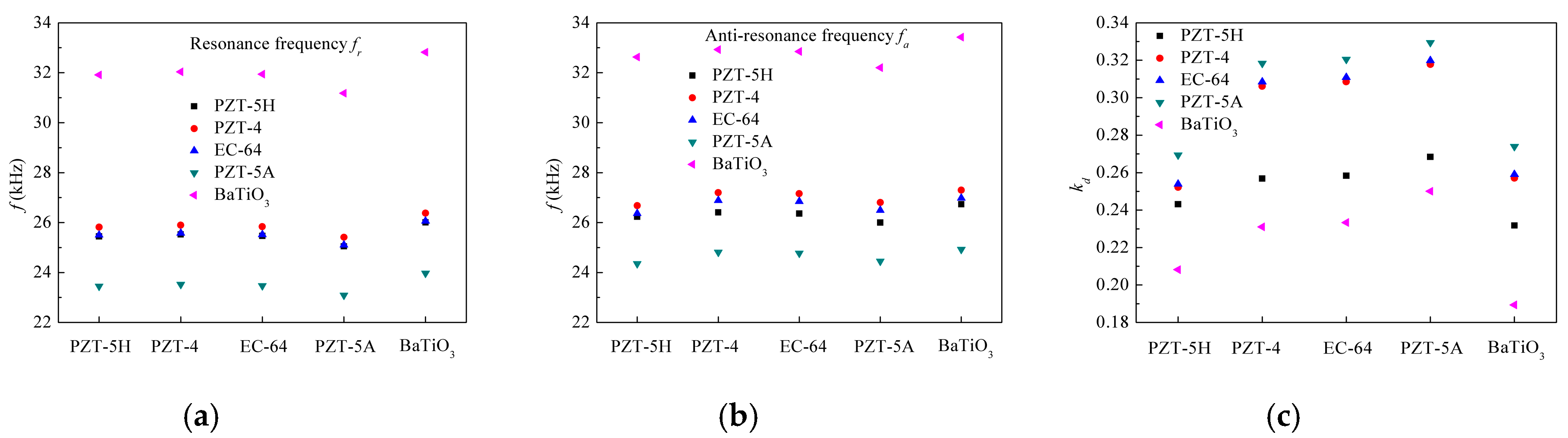
4.2. Effect of Piezoceramic Material Types

Selecting the material parameters of epoxy layers as the sequence ①-①-① and keeping geometric dimensions of the transducer unchanged, Figure 10 gives the effect of combinations of five commonly used piezoceramic materials on the electromechanical characteristics. These piezoceramic materials include PZT-5H, PZT-4, EC-64, PZT-5A and BaTiO3, of which material parameters are shown in Table 3. The piezoceramic material types of PZT ring #1 are marked in the abscissa. The piezoceramic material types of PZT ring #2 are listed in the graph. From Figure 10, it can be found that when the PZT ring #2 is chosen as PZT-5A, the transducer has the minimum first resonance and anti-resonance frequencies, but the maximum first electromechanical coupling factor. When the PZT ring #2 is chosen as BaTiO3, the transducer has the maximum first resonance and anti-resonance frequencies, but the minimum first electromechanical coupling factor. When the PZT ring #2 are chosen as PZT-5H, PZT-4, EC-64, the transducer has the similar first resonance and anti-resonance frequencies. The reasons are as follows. For a piezoelectric circular ring in radial vibration, when keeping its geometric sizes unchanged, its resonance frequency depends on the radial sound speed V r P = c 11 E / ρ P [36]. The radial sound speed reflects its stiffness–mass ratio, of which values are listed in Table 1. A larger V r P for PZT ring #2 means its stiffness is enhanced, which further induces the stiffness increase of the transducer. In addition, its electromechanical coupling effect depends on the plane coupling factor k P ( p ) = 2 d 31 2 / [ κ 33 σ ( s 11 E + s 12 E ) [36], as shown in Table 1. A larger k P ( p ) for PZT ring #2 means its electromechanical coupling effect is better, which further improves the whole coupling effect. The PZT-5A has the minimum V r P and maximum k P ( p ) ; therefore, the transducer with PZT-5A ring #2 has the smallest resonance frequency and best electromechanical coupling effect than the other types.

4.3. Effect of Locations of Piezoceramic Rings

Selecting the material parameters of epoxy layers as the sequence ①-①-①, piezoceramic material types of two PZT rings as PZT-5H, and keeping the area of one pizeoceramic ring unchanged, Figure 11 shows the relations between the electromechanical characteristics and locations of the other piezoceramic rings. Here, the inner radii R1 and R3 of the PZT rings #1 and #2 are used to denote their locations, respectively. The corresponding outer radii R2 and R4 of the PZT rings #1 and #2 also need to be changed to maintain the same areas, which are defined as R 2 = S 1 / π + R 1 2 and R 4 = S 2 / π + R 3 2 , respectively. Symbols S 1 and S 2 are the areas of the PZT rings #1 and #2, respectively. When fixing the location of PZT ring #1 and varying the location of PZT ring #2, the inner and outer radii R3 and R4 of the PZT ring #2, and the areas of the epoxy rings #2 and #3 also vary. When fixing the location of PZT ring #2 and varying the location of PZT ring #1, the inner and outer radii R1 and R2 of the PZT ring #1, and the areas of the epoxy disk #1 and ring #2 also vary. From Figure 11, it is indicated that when the location of PZT ring #1 is fixed, the first resonance and anti-resonance frequencies, as well as the first electromechanical coupling factor, decrease with the increase of location of PZT ring #2. When the location of PZT ring #2 is fixed, the first resonance and anti-resonance frequencies, as well as the first electromechanical coupling factor, firstly increase to the maximum values, and then decrease. That is because different locations of one piezoelectric ring relative to the other will change the geometric sizes itself and those of the adjacent epoxy layers. When the material parameters are unchanged, these variations in the geometric sizes will vary their stiffness and mass, which lead to the change in the electromechanical coupling effect of the transducer. In Figure 11b, three maximum values are fr = 25.685 kHz, fa = 26.578 kHz, kd = 0.26, respectively. The corresponding locations are R1 = 12 mm, 12.5 mm, and 14 mm, respectively. This rule can be used to design the improved transducer that has the maximum first resonance and anti-resonance frequencies as well as the first electromechanical coupling factor.

5. Conclusions

A parametric analysis was performed to study the effects of multiple key factors, including material parameters of epoxy layers, piezoceramic material types, and locations of piezoceramic rings, on the electromechanical characteristics of the radially layered cylindrical piezoceramic/epoxy composite transducer. The main results can be concluded as follow.
(1) Based on the presented three different epoxy materials that have the same Poisson’s ratio, approximately equal density and the certain difference in Young’s modulus, the transducer can present 27 sets of electromechanical characteristics by utilizing different material sequences. Furthermore, these electromechanical characteristics are mainly controlled by the Young’s moduli of the epoxy layers, especially for that of the epoxy ring #2. This result demonstrates that only regulating the Young’s modulus of the epoxy layers can realize the design and optimization of the electromechanical characteristics of the transducer.
(2) Among five commonly used piezoceramic materials (PZT-5H, PZT-4, EC-64, PZT-5A and BaTiO3), the transducer with the PZT-5A ring #2 has the minimum first resonance and anti-resonance frequencies as well as the maximum first electromechanical coupling factor; the transducer with the BaTiO3 ring #2 has the maximum first resonance and anti-resonance frequencies as well as the minimum first electromechanical coupling factor; the transducer with PZT-5H, PZT-4, EC-64 ring #2 has the similar first resonance and anti-resonance frequencies. That is to say, the selections of piezoceramic material types in the ring #2, the piezoceramic materials with the lager radial sound speed and plane electromechanical coupling factor can optimize the electromechanical characteristics of the transducer.
(3) The locations of piezoceramic rings have great effects on the electromechanical characteristics of the transducer, in particular, an appropriate location can be used to optimize the transducer design, making it have the maximum first resonance and anti-resonance frequencies as well as the first electromechanical coupling factor.

Author Contributions

J.W. established the modelling and performed the numerical analysis; J.W., L.Q. and W.S. fabricated the transducer; J.W. and L.Q. tested the transducer; J.W. and W.L. wrote the paper; and all the authors discussed the results.

Funding

This research was funded by the National Natural Science Foundation of China (51708025, 61671068) and the Fundamental Research Funds for the Central Universities (FRF-TP-16-069A1).

Conflicts of Interest

The authors declare no conflicts of interest.

Appendix A

{ A E ( 1 ) = v 9 V 0 B E ( 1 ) = 0 ,
{ A P ( 1 ) = ( a 1 v 9 + v 1 ) V 0 B P ( 1 ) = ( a 2 v 9 + v 2 ) V 0 ,
{ A E ( 2 ) = ( a 3 v 9 + v 3 ) V 0 B E ( 2 ) = ( a 4 v 9 + v 4 ) V 0 ,
{ A P ( 2 ) = ( a 5 v 9 + v 5 ) V 0 B P ( 2 ) = ( a 6 v 9 + v 6 ) V 0 ,
{ A E ( 3 ) = ( a 7 v 9 + v 7 ) V 0 B E ( 3 ) = ( a 8 v 9 + v 8 ) V 0 ,
where
{ H 1 = f 1 ( R 1 , 1 ) f 4 ( R 1 , 1 ) f 3 ( R 1 , 1 ) f 2 ( R 1 , 1 ) a 1 = [ f 5 ( R 1 , 1 ) f 4 ( R 1 , 1 ) f 7 ( R 1 , 1 ) f 2 ( R 1 , 1 ) ] / H 1 v 1 = [ ( e 31 ( 1 ) / h ) f 2 ( R 1 , 1 ) ] / H 1 a 2 = [ f 5 ( R 1 , 1 ) f 3 ( R 1 , 1 ) f 7 ( R 1 , 1 ) f 1 ( R 1 , 1 ) ] / H 1 v 2 = [ ( e 31 ( 1 ) / h ) f 1 ( R 1 , 1 ) ] / H 1 ,
{ H 2 = f 5 ( R 2 , 2 ) f 8 ( R 2 , 2 ) f 7 ( R 2 , 2 ) f 6 ( R 2 , 2 ) a 3 = { f 8 ( R 2 , 2 ) [ a 1 f 1 ( R 2 , 1 ) + a 2 f 2 ( R 2 , 1 ) ] f 6 ( R 2 , 2 ) [ a 1 f 3 ( R 2 , 1 ) + a 2 f 4 ( R 2 , 1 ) ] } / H 2 v 3 = { f 8 ( R 2 , 2 ) [ v 1 f 1 ( R 2 , 1 ) + v 2 f 2 ( R 2 , 1 ) ] f 6 ( R 2 , 2 ) [ v 1 f 3 ( R 2 , 1 ) + v 2 f 4 ( R 2 , 1 ) + e 31 ( 1 ) / h ] } / H 2 a 4 = { f 7 ( R 2 , 2 ) [ a 1 f 1 ( R 2 , 1 ) + a 2 f 2 ( R 2 , 1 ) ] f 5 ( R 2 , 2 ) [ a 1 f 3 ( R 2 , 1 ) + a 2 f 4 ( R 2 , 1 ) ] } / H 2 v 4 = { f 7 ( R 2 , 2 ) [ v 1 f 1 ( R 2 , 1 ) + v 2 f 2 ( R 2 , 1 ) ] f 5 ( R 2 , 2 ) [ v 1 f 3 ( R 2 , 1 ) + v 2 f 4 ( R 2 , 1 ) + e 31 ( 1 ) / h ] } / H 2 ,
{ H 3 = f 1 ( R 3 , 2 ) f 4 ( R 3 , 2 ) f 3 ( R 3 , 2 ) f 2 ( R 3 , 2 ) a 5 = { f 4 ( R 3 , 2 ) [ a 3 f 5 ( R 3 , 2 ) + a 4 f 6 ( R 3 , 2 ) ] f 2 ( R 3 , 2 ) [ a 3 f 7 ( R 3 , 2 ) + a 4 f 8 ( R 3 , 2 ) ] } / H 3 v 5 = { f 4 ( R 3 , 2 ) [ v 3 f 5 ( R 3 , 2 ) + v 4 f 6 ( R 3 , 2 ) ] f 2 ( R 3 , 2 ) [ v 3 f 7 ( R 3 , 2 ) + v 4 f 8 ( R 3 , 2 ) e 31 ( 2 ) / h ] } / H 3 a 6 = { f 3 ( R 3 , 2 ) [ a 3 f 5 ( R 3 , 2 ) + a 4 f 6 ( R 3 , 2 ) ] f 1 ( R 3 , 2 ) [ a 3 f 7 ( R 3 , 2 ) + a 4 f 8 ( R 3 , 2 ) ] } / H 3 v 6 = { f 3 ( R 3 , 2 ) [ v 3 f 5 ( R 3 , 2 ) + v 4 f 6 ( R 3 , 2 ) ] f 1 ( R 3 , 2 ) [ v 3 f 7 ( R 3 , 2 ) + v 4 f 8 ( R 3 , 2 ) e 31 ( 2 ) / h ] } / H 3 ,
{ H 4 = f 5 ( R 4 , 3 ) f 8 ( R 4 , 3 ) f 7 ( R 4 , 3 ) f 6 ( R 4 , 3 ) a 7 = { f 8 ( R 4 , 3 ) [ a 5 f 1 ( R 4 , 2 ) + a 6 f 2 ( R 4 , 2 ) ] f 6 ( R 4 , 3 ) [ a 5 f 3 ( R 4 , 2 ) + a 6 f 4 ( R 4 , 2 ) ] } / H 4 v 7 = { f 8 ( R 4 , 3 ) [ v 5 f 1 ( R 4 , 2 ) + v 6 f 2 ( R 4 , 2 ) ] f 6 ( R 4 , 3 ) [ v 5 f 3 ( R 4 , 2 ) + v 6 f 4 ( R 4 , 2 ) e 31 ( 2 ) / h ] } / H 4 a 8 = { f 7 ( R 4 , 3 ) [ a 5 f 1 ( R 4 , 2 ) + a 6 f 2 ( R 4 , 2 ) ] f 5 ( R 4 , 3 ) [ a 5 f 3 ( R 4 , 2 ) + a 6 f 4 ( R 4 , 2 ) ] } / H 4 v 8 = { f 7 ( R 4 , 3 ) [ v 5 f 1 ( R 4 , 2 ) + v 6 f 2 ( R 4 , 2 ) ] f 5 ( R 4 , 3 ) [ v 5 f 3 ( R 4 , 2 ) + v 6 f 4 ( R 4 , 2 ) e 31 ( 2 ) / h ] } / H 4 ,
v 9 = [ v 7 f 7 ( R 5 , 3 ) + v 8 f 8 ( R 5 , 3 ) ] / [ a 7 f 7 ( R 5 , 3 ) + a 8 f 8 ( R 5 , 3 ) ] .

References

  1. Maréchal, P.; Levassort, F.; Holc, J.; Tran-Huu-Hue, L.-P.; Kosec, M.; Lethiecq, M. High-frequency transducers based on integrated piezoelectric thick films for medical imaging. IEEE Trans. Ultrason. Ferroelectr. Freq. Control 2006, 53, 1524–1533. [Google Scholar] [CrossRef] [PubMed]
  2. Shung, K.K.; Cannata, J.; Zhou, Q. Piezoelectric materials for high frequency medical imaging applications: A review. J. Electroceram. 2007, 19, 141–147. [Google Scholar] [CrossRef]
  3. Cannata, J.M.; Williams, J.A.; Zhou, Q.; Ritter, T.A.; Shung, K.K. Development of a 35-MHz piezo-composite ultrasound array for medical imaging. IEEE Trans. Ultrason. Ferroelectr. Freq. Control 2006, 53, 224–236. [Google Scholar] [CrossRef] [PubMed] [Green Version]
  4. Tawie, R.; Lee, H.-K.; Park, S. Non-destructive evaluation of concrete quality using PZT transducers. Smart Struct. Syst. 2010, 6, 851–866. [Google Scholar] [CrossRef]
  5. Lim, Y.Y.; Kwong, K.Z.; Liew, W.Y.H.; Soh, C.K. Non-destructive concrete strength evaluation using smart piezoelectric transducer—A comparative study. Smart Mater. Struct. 2016, 25, 085021. [Google Scholar] [CrossRef]
  6. Martins, M.; Correia, V.; Cabral, J.; Lanceros-Mendez, S.; Rocha, J. Optimization of piezoelectric ultrasound emitter transducers for underwater communications. Sens. Actuators A Phys. 2012, 184, 141–148. [Google Scholar] [CrossRef]
  7. Mosca, F.; Matte, G.; Shimura, T. Low-frequency source for very long-range underwater communication. J. Acoust. Soc. Am. 2013, 133, EL61–EL67. [Google Scholar] [CrossRef] [PubMed]
  8. Sun, J.; Ngernchuklin, P.; Vittadello, M.; Akdoğan, E.; Safari, A. Development of 2-2 piezoelectric ceramic/polymer composites by direct-write technique. J. Electroceram. 2010, 24, 219–225. [Google Scholar] [CrossRef]
  9. Lee, H.J.; Zhang, S.; Bar-Cohen, Y.; Sherrit, S. High temperature, high power piezoelectric composite transducers. Sensors 2014, 14, 14526–14552. [Google Scholar] [CrossRef] [PubMed]
  10. Li, L.; Zhang, S.; Xu, Z.; Wen, F.; Geng, X.; Lee, H.J.; Shrout, T.R. 1-3 piezoelectric composites for high-temperature transducer applications. J. Phys. D Appl. Phys. 2013, 46, 165306. [Google Scholar] [CrossRef] [PubMed]
  11. Chabok, H.R.; Cannata, J.M.; Kim, H.H.; Williams, J.A.; Park, J.; Shung, K.K. A high-frequency annular-array transducer using an interdigital bonded 1-3 composite. IEEE Trans. Ultrason. Ferroelectr. Freq. Control 2011, 58, 206–214. [Google Scholar] [CrossRef] [PubMed] [Green Version]
  12. Garcia-Gancedo, L.; Olhero, S.M.; Alves, F.J.; Ferreira, J.M.F.; Demore, C.E.M.; Cochran, S.; Button, T.W. Application of gel-casting to the fabrication of 1-3 piezoelectric ceramic-polymer composites for high-frequency ultrasound devices. J. Micromech. Microeng. 2012, 22, 125001. [Google Scholar] [CrossRef]
  13. Lee, H.J.; Zhang, S.; Geng, X.; Shrout, T.R. Electroacoustic response of 1-3 piezocomposite transducers for high power applications. Appl. Phys. Lett. 2012, 101, 253504. [Google Scholar] [CrossRef] [PubMed] [Green Version]
  14. Lee, H.J.; Zhang, S. Design of low-loss 1-3 piezoelectric composites for high-power transducer applications. IEEE Trans. Ultrason. Ferroelectr. Freq. Control 2012, 59, 1969–1975. [Google Scholar] [PubMed] [Green Version]
  15. Lee, H.J.; Zhang, S.; Meyer, R.J., Jr.; Sherlock, N.P.; Shrout, T.R. Characterization of piezoelectric ceramics and 1-3 composites for high power transducers. Appl. Phys. Lett. 2012, 101, 032902. [Google Scholar] [CrossRef] [PubMed] [Green Version]
  16. Abrar, A.; Zhang, D.; Su, B.; Button, T.W.; Kirk, K.J.; Cochran, S. 1-3 connectivity piezoelectric ceramic-polymer composite transducers made with viscous polymer processing for high frequency ultrasound. Ultrasonics 2004, 42, 479–484. [Google Scholar] [CrossRef] [PubMed]
  17. Wang, W.; Or, S.W.; Yue, Q.; Zhang, Y.; Jiao, J.; Ren, B.; Lin, D.; Leung, C.M.; Zhao, X.; Luo, H. Cylindrically shaped ultrasonic linear array fabricated using PIMNT/epoxy 1-3 piezoelectric composite. Sens. Actuators A Phys. 2013, 192, 69–75. [Google Scholar] [CrossRef]
  18. Zhang, Y.; Wang, L.; Qin, L. Equivalent parameter model of 1-3 piezocomposite with a sandwich polymer. Results Phys. 2018, 9, 1256–1261. [Google Scholar] [CrossRef]
  19. Zhang, Y.; Jiang, Y.; Lin, X.; Xie, R.; Zhou, K.; Button, T.W.; Zhang, D. Fine-scaled piezoelectric ceramic/polymer 2-2 composites for high-frequency transducer. J. Am. Ceram. Soc. 2014, 97, 1060–1064. [Google Scholar] [CrossRef]
  20. Cannata, J.M.; Williams, J.A.; Zhang, L.; Hu, C.-H.; Shung, K.K. A high-frequency linear ultrasonic array utilizing an interdigitally bonded 2-2 piezo-composite. IEEE Trans. Ultrason. Ferroelectr. Freq. Control 2011, 58, 2202–2212. [Google Scholar] [CrossRef] [PubMed] [Green Version]
  21. Ritter, T.A.; Shrout, T.R.; Tutwiler, R.; Shung, K.K. A 30-MHz piezo-composite ultrasound array for medical imaging applications. IEEE Trans. Ultrason. Ferroelectr. Freq. Control 2002, 49, 217–230. [Google Scholar] [CrossRef] [PubMed]
  22. Banerjee, S.; Cook-Chennault, K.A. Influence of al particle size and lead zirconate titanate (PZT) volume fraction on the dielectric properties of pzt-epoxy-aluminum composites. J. Eng. Mater. Technol. 2011, 133, 041016. [Google Scholar] [CrossRef]
  23. Banerjee, S.; Cook-Chennault, K.A. An investigation into the influence of electrically conductive particle size on electromechanical coupling and effective dielectric strain coefficients in three phase composite piezoelectric polymers. Compos. Part A Appl. Sci. Manuf. 2012, 43, 1612–1619. [Google Scholar] [CrossRef]
  24. Sundar, U.; Cook-Chennault, K.A.; Banerjee, S.; Refour, E. Dielectric and piezoelectric properties of percolative three-phase piezoelectric polymer composites. J. Vac. Sci. Technol. B 2016, 34, 041232. [Google Scholar] [CrossRef]
  25. Lin, S. Effect of electric load impedances on the performance of sandwich piezoelectric transducers. IEEE Trans. Ultrason. Ferroelectr. Freq. Control 2004, 51, 1280–1286. [Google Scholar] [PubMed]
  26. Lin, S. Analysis of multifrequency langevin composite ultrasonic transducers. IEEE Trans. Ultrason. Ferroelectr. Freq. Control 2009, 56, 1990–1998. [Google Scholar] [PubMed]
  27. Lin, S.; Xu, C. Analysis of the sandwich ultrasonic transducer with two sets of piezoelectric elements. Smart Mater. Struct. 2008, 17, 065008. [Google Scholar] [CrossRef]
  28. Arnold, F.J.; Bravo-Roger, L.L.; Gonçalves, M.S.; Grilo, M. Characterization of sandwiched piezoelectric transducers-a complement for teaching electric circuits. Lat.-Am. J. Phys. Educ. 2012, 6, 216–220. [Google Scholar]
  29. Arnold, F.J.; Mühlen, S.S. The resonance frequencies on mechanically pre-stressed ultrasonic piezotransducers. Ultrasonics 2001, 39, 1–5. [Google Scholar] [CrossRef]
  30. Adelman, N.T.; Stavsky, Y.; Segal, E. Axisymmetric vibrations of radially polarized piezoelectric ceramic cylinders. J. Sound Vib. 1975, 38, 245–254. [Google Scholar] [CrossRef]
  31. Ebenezer, D.D.; Abraham, P. Eigenfunction analysis of radially polarized piezoelectric cylindrical shells of finite length. J. Acoust. Soc. Am. 1997, 102, 1549–1558. [Google Scholar] [CrossRef]
  32. Hussein, M.; Heyliger, P. Discrete layer analysis of axisymmetric vibrations of laminated piezoelectric cylinders. J. Sound Vib. 1996, 192, 995–1013. [Google Scholar] [CrossRef]
  33. Kim, J.O.; Hwang, K.K.; Jeong, H.G. Radial vibration characteristics of piezoelectric cylindrical transducers. J. Sound Vib. 2004, 276, 1135–1144. [Google Scholar] [CrossRef]
  34. Kim, J.O.; Lee, J.G. Dynamic characteristics of piezoelectric cylindrical transducers with radial polarization. J. Sound Vib. 2007, 300, 241–249. [Google Scholar] [CrossRef]
  35. Li, X.F.; Peng, X.L.; Lee, K.Y. Radially polarized functionally graded piezoelectric hollow cylinders as sensors and actuators. Eur. J. Mech. A Solids 2010, 29, 704–713. [Google Scholar] [CrossRef]
  36. Lin, S. Electro-mechanical equivalent circuit of a piezoelectric ceramic thin circular ring in radial vibration. Sens. Actuators A Phys. 2007, 134, 505–512. [Google Scholar] [CrossRef]
  37. Lin, S.; Wang, S.J.; Fu, Z.Q. Electro-mechanical equivalent circuit for the radial vibration of the radially poled piezoelectric ceramic long tubes with arbitrary wall thickness. Sens. Actuators A Phys. 2012, 180, 87–96. [Google Scholar] [CrossRef]
  38. Piao, C.; Kim, J.O. Vibration characteristics of a piezoelectric transducer laminated with piezoelectric disks. Noise Control Eng. J. 2016, 64, 444–458. [Google Scholar] [CrossRef]
  39. Piao, C.; Kim, J.O. Vibration characteristics of an ultrasonic transducer of two piezoelectric discs. Ultrasonics 2017, 74, 72–80. [Google Scholar] [CrossRef] [PubMed]
  40. Zhang, T.T.; Shi, Z.F. Exact analyses for two kinds of piezoelectric hollow cylinders with graded properties. Smart Struct. Syst. 2010, 6, 975–989. [Google Scholar] [CrossRef]
  41. Zhang, T.T.; Shi, Z.F.; Spencer, B.F., Jr. Vibration analysis of a functionally graded piezoelectric cylindrical actuator. Smart Mater. Struct. 2008, 17, 025018. [Google Scholar] [CrossRef]
  42. Ebenezer, D.D. Determination of complex coefficients of radially polarized piezoelectric ceramic cylindrical shells using thin shell theory. IEEE Trans. Ultrason. Ferroelectr. Freq. Control 2004, 51, 1209–1215. [Google Scholar] [CrossRef] [PubMed]
  43. Ebenezer, D.D.; Joseph, L. Frequency-dependent open-circuit acoustic sensitivity of fluid-filled, coated, radially polarized piezoelectric ceramic cylindrical shells of arbitrary thickness and infinite length. IEEE Trans. Ultrason. Ferroelectr. Freq. Control 2001, 48, 914–921. [Google Scholar] [CrossRef] [PubMed]
  44. Huan, Q.; Miao, H.; Li, F. A uniform-sensitivity omnidirectional shear-horizontal (SH) wave transducer based on a thickness poled, thickness-shear (d15) piezoelectric ring. Smart Mater. Struct. 2017, 26, 08LT01. [Google Scholar] [CrossRef] [Green Version]
  45. Huan, Q.; Miao, H.; Li, F. A variable-frequency structural health monitoring system based on omnidirectional shear horizontal wave piezoelectric transducers. Smart Mater. Struct. 2018, 27, 025008. [Google Scholar] [CrossRef] [Green Version]
  46. Gao, W.; Huo, L.; Li, H.; Song, G. Smart concrete slabs with embedded tubular pzt transducers for damage detection. Smart Mater. Struct. 2018, 27, 025002. [Google Scholar] [CrossRef]
  47. Gao, W.; Huo, L.; Li, H.; Song, G. An embedded tubular PZT transducer based damage imaging method for two-dimensional concrete structures. IEEE Access 2018, 6, 30100–30109. [Google Scholar] [CrossRef]
  48. Hu, J.; Lin, S.; Zhang, X.; Wang, Y. Radially sandwiched composite transducers composed of the radially polarized piezoelectric ceramic circular ring and metal rings. Acta Acust. United Acust. 2014, 100, 418–426. [Google Scholar] [CrossRef]
  49. Cui, M.-T.; Xue, S.; Guo, R.-B.; Su, M.; Li, Y.-C.; Qian, M. Design and fabrication of cylindrical transducer based on 2-2 piezoelectric composite. In Proceedings of the 2015 Symposium on Piezoelectricity, Acoustic Waves, and Device Applications (SPAWDA), Jinan, China, 30 October–2 November 2015; pp. 277–281. [Google Scholar]
  50. Zhou, D.; Cheung, K.F.; Chen, Y.; Lau, S.T.; Zhou, Q.; Shung, K.K.; Luo, H.S.; Dai, J.; Chan, H.L.W. Fabrication and performance of endoscopic ultrasound radial arrays based on PMN-PT single crystal/epoxy 1-3 composite. IEEE Trans. Ultrason. Ferroelectr. Freq. Control 2011, 58, 477–484. [Google Scholar] [CrossRef] [PubMed] [Green Version]
  51. Wang, H.; Wang, L. High frequency wide band underwater acoustic transducer for ring shaped composite material. Acta Acust. 2017, 42, 53–59. [Google Scholar]
  52. Wang, J.J.; Qin, L.; Song, W.B.; Shi, Z.F.; Song, G. Electromechanical characteristics of radially layered piezoceramic/epoxy cylindrical composite transducers: Theoretical solution, numerical simulation and experimental verification. IEEE Trans. Ultrason. Ferroelectr. Freq. Control 2018, 65, 1643–1656. [Google Scholar] [CrossRef] [PubMed]
  53. Wang, J.J.; Shi, Z.F. Dynamic characteristics of an axially polarized multilayer piezoelectric/elastic composite cylindrical transducer. IEEE Trans. Ultrason. Ferroelectr. Freq. Control 2013, 60, 2196–2203. [Google Scholar] [CrossRef] [PubMed]
  54. Wang, J.J.; Shi, Z.F. Models for designing radially polarized multilayer piezoelectric/elastic composite cylindrical transducers. J. Intell. Mater. Syst. Struct. 2016, 27, 500–511. [Google Scholar] [CrossRef]
  55. Mason, W.P. Piezoelectric Crystals and Their Application to Ultrasonics; Van Nostrand Reinhold: New York, NY, USA, 1950. [Google Scholar]
  56. Kim, D.; Kim, J.O.; Il Jung, S. Vibration characteristics of a piezoelectric open-shell transducer. J. Sound Vib. 2012, 331, 2038–2054. [Google Scholar] [CrossRef]
  57. Butler, J.L.; Sherman, C.H. Transducers and Arrays for Underwater Sound; Springer: Cham, Switzerland, 2016. [Google Scholar]
  58. Berlincourt, D.; Cmolik, C.; Jaffe, H. Piezoelectric properties of polycrystalline lead titanate zirconate compositions. Proc. IRE 1960, 48, 220–229. [Google Scholar] [CrossRef]
  59. Avellaneda, M.; Swart, P.J. Calculating the performance of 1–3 piezoelectric composites for hydrophone applications: An effective medium approach. J. Acoust. Soc. Am. 1998, 103, 1449–1467. [Google Scholar] [CrossRef]
  60. Hayward, G.; Bennett, J.; Hamilton, R. A theoretical study on the influence of some constituent material properties on the behavior of 1-3 connectivity composite transducers. J. Acoust. Soc. Am. 1995, 98, 2187–2196. [Google Scholar] [CrossRef]
  61. Smith, W.A. Optimizing electromechanical coupling in piezocomposites using polymers with negative poisson’s ratio. In Proceedings of the IEEE 1991 Ultrasonics Symposium, Orlando, FL, USA, 8–11 December 1991; pp. 661–666. [Google Scholar]
Figure 1. Schematic representation of the radially layered cylindrical piezoceramic/epoxy composite transducer.
Micromachines 09 00585 g001
Figure 2. Three-dimensional finite element model of one-twelfth of the transducer.
Micromachines 09 00585 g002
Figure 3. Theoretical and simulated impedance spectra.
Micromachines 09 00585 g003
Figure 4. Experimental setup: (a) the fabricated specimen; (b) the impedance test system.
Micromachines 09 00585 g004
Figure 5. Measured impedance spectrum and its phase.
Micromachines 09 00585 g005
Figure 6. Electromechanical characteristics of the transducers with different material sequences of the epoxy layers.
Micromachines 09 00585 g006
Figure 7. Influence of density of the epoxy layers on the electromechanical characteristics of the transducer. Error = (Reference group − Comparison group)/Reference group.
Micromachines 09 00585 g007
Figure 8. Influence of Young’s modulus of the epoxy layers on the electromechanical characteristics of the transducer. Error = (Reference group − Comparison group)/Reference group.
Micromachines 09 00585 g008
Figure 9. Electromechanical characteristics versus Young’s moduli of the epoxy layers: (a) all epoxy layers; (b) only epoxy disk #1; (c) only epoxy ring #2; (d) only epoxy ring #3.
Micromachines 09 00585 g009
Figure 10. Electromechanical characteristics: (a) resonance frequency fr; (b) anti-resonance frequency fa; (c) electromechanical coupling factor kd versus piezoceramic material types.
Micromachines 09 00585 g010
Figure 11. Electromechanical characteristics versus locations of piezoceramic rings: (a) location of PZT ring #2; (b) location of PZT ring #1.
Micromachines 09 00585 g011
Table 1. Material parameters of piezoceramic materials [52,56,57,58].
Material TypesElastic Constant ( × 10 12   m 2 / N ) Piezoelectric Constant ( × 10 12   C / N ) Dielectric ConstantDensity ( kg / m 3 ) Radial Sound Speed ( m / s ) Plane Electromechanical Coupling Factor
s 11 E s 12 E   d 31 κ 33 σ / ε 0 ρ P V r P k P ( p )
PZT-5H13−4.29−1864500745034040.45
PZT-412.3−4.05−1231300750034870.56
EC-6412.8−4.2−1271300750034170.57
PZT-5A16.4−5.74−1711700775029940.60
BaTiO38.55−2.61−791900570047570.35
Permittivity of free space: ε 0 = 8.85 × 10 12   F / m .
Table 2. Material parameters of three types of epoxy materials.
Epoxy TypesYoung’s Modulus ( × 10 6   N / m 2 ) Poisson’s RatioDensity ( kg / m 3 )
E ¯ μ ρ E
2301.470.431186
2862.170.431197
29300.431205
Table 3. Comparisons between the calculated, simulated and experimental frequencies.
First Resonance and Anti-Resonance FrequenciesTheory
(kHz)
ANSYS
(kHz)
Error 1
(%)
Experiment
(kHz)
Error 2
(%)
fr26.15426.497−1.3123.17911.37
fa26.99527.504−1.8923.78011.91
Error 1 = (Theory − ANSYS)/Theory; Error 2 = (Theory − Experiment)/Theory.

