1. Introduction
The incidence of type 2 diabetes mellitus is rapidly increasing [
1]. Conventionally, the levels of HbA1c and fasting plasma glucose are used as proxies for detection of early-stage diabetes in routine health check-ups; however, neither method is sufficiently sensitive. The Diabetes Epidemiology Collaborative Analysis of Diagnostic Criteria in Europe and Diabetes Epidemiology Collaborative Analysis of Diagnostic Criteria in Asia studies have shown that the presence of hyperglycemia after a glucose load is associated with elevated risk for cardiovascular disease, even in individuals with early-stage diabetes [
2,
3]. For detecting hyperglycemia, however, multiple blood sampling is necessary. The availability of a system for estimating postprandial glucose excursion without the need for blood sampling would be beneficial. Therefore, we investigated and developed such a system on the basis of the estimation of the glucose area under the curve (AUC) value using minimally invasive interstitial fluid extraction technology (MIET) [
4,
5]. In the MIET procedure, a microneedle array (length 300 μm) is stamped on the forearm skin as pretreatment to enhance interstitial fluid (ISF) extraction. Subsequently, a hydrogel patch is placed on the pretreated area to accumulate ISF for a specific period. The ISF extraction level is determined from the glucose AUC during this time and is measured by analyzing the glucose levels in the hydrogel with the simultaneous measurement of sodium ion levels as an internal standard for ISF extraction. The glucose levels in the hydrogel are dependent on both the formation of skin micropores and the blood glucose levels during measurement. In contrast, sodium ion levels in the hydrogel are only dependent on the formation of the skin micropores because the levels show only a narrow variation among individuals, in addition to the low circadian and day-to-day variations in an individual. Therefore, we use sodium ion levels to calibrate differences in ISF glucose extraction [
4]. No additional force beyond passive diffusion and osmotic pressure is needed to extract the ISF from the skin. This easy-to-use glucose monitoring system may be a useful tool for not only screening [
6] but also enhancing patients’ understanding of the correlation between individual foods and postprandial glucose excursion [
7]. In these clinical studies, however, the hydrogel patches after extracting ISF were immersed into pure water for several hours to extract glucose and sodium ions. This was because the glucose was measured by a fluorescence microplate reader, and the sodium ions were measured by a combination of sodium and potassium ion-selective electrodes (ISEs) or by ion chromatography. It would be very useful if we could measure the glucose and sodium ions in a hydrogel patch directly. Therefore, in this study, we developed a small, integrated glucose sensor with a high-selectivity, all-solid-state sodium ISE. The hydrogel consisted of polyvinyl alcohol and a 268 mM (10
−0.57 M) KCl solvent for osmotic adjustment, and the hydrogel size was ϕ = 10 mm. Previous clinical studies showed that glucose levels in hydrogel were between 0.6 and 20 mg/dL (0.03–1.1 mM) and the sodium ion levels ranged from 0.4 to 14 mM (from 10
−3.4 to 10
−1.9 M) [
4,
5,
6]. Although the physiological glucose level of diabetes patients is 40–400 mg/dL (2.2–22 mM) and their physiological level of sodium ions is around 140 mM (10
−0.85 M), the levels of glucose and sodium ions in the hydrogel are more than ten times lower than those in blood. This is because small amounts of ISF glucose and sodium ions are extracted through micropores and are diluted by the solvent in the hydrogels. Therefore, high sensitivity is required for our glucose and sodium ion sensors.
Glucose sensors have been widely developed around the world, mostly for self-monitoring blood glucose. Such sensors are meant to measure blood glucose levels, therefore, the sensitivity is not sufficient to measure the glucose levels in the hydrogels of our minimally invasive glucose monitoring. On the other hand, many highly sensitive glucose sensors have been reported thus far: Yao
et al. developed an immobilized glucose oxidase (GOD) glucose sensor, and its lower limit was 9 nM [
8]. Its operation was based on measuring the increase of the anodic current during the oxidation of hydrogen peroxide (H
2O
2). H
2O
2 is produced from the oxidation of glucose by dissolved oxygen in the presence of GOD [
9]. Because Ikariyama
et al. also developed a ϕ = 10 µm–immobilized GOD glucose sensor [
10], a GOD-fixed glucose sensor could possibly be miniaturized and exhibit high sensitivity.
ISEs are often used to analyze ionic components in a liquid sample; however, there were two difficulties facing the development of a sodium ISE for the hydrogel measurement. First, because of the 268 mM KCl in the hydrogel for osmotic adjustment, high Na
+/K
+ selectivity was necessary for the ionophore of the sodium ion-selective membrane. Because the Na
+/K
+ selectivity of conventional ionophore Bis12-crown-4 is 100
= −2) [
11], a conventional ISE using Bis12-crown-4 is unsuitable for hydrogel measurement. Hence, we decided to use DD16C5 as an ionophore because it shows a high Na
+/K
+ selectivity (about 1000, (
= −3).
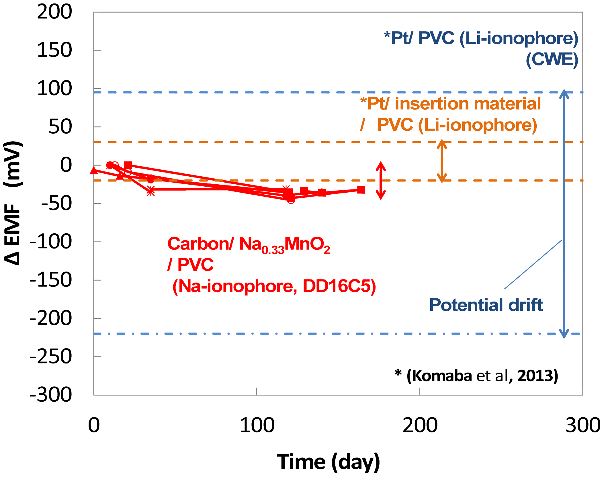
Second, to measure hydrogel samples (ϕ = 10 mm), sensors needed to be miniaturized. Conventional ISEs have internal reference and solution, making them difficult to miniaturize. Hence, for the purposes of miniaturization, all-solid-state ISEs have been widely studied. Although coated-wire electrodes, metallic wire electrodes directly covered with an ion-selective membrane has been studied as all-solid-state ISEs since 1971, they generally show insufficient potential stability. To achieve the potential stability and miniaturization of sodium ISEs, an insertion material Na
0.33MnO
2 has been studied for all-solid-state ISEs [
12,
13]. Komaba
et al. reported that the ISE using Na
0.33MnO
2 as an inner contact layer is highly efficient for stabilization [
13]. This stabilization of the membrane potential was because the interface resistance at the electrode reduced drastically.
In this study, we developed a highly sensitive GOD-fixed glucose sensor that incorporated a high-selectivity, miniaturized sodium ISE using the insertion material Na0.33MnO2 as an inner contact layer and DD16C5 as an ionophore. We evaluated the response time, Na+/K+ selectivity, accuracy, precision in hydrogel measurement, long stability, and potential drift in solution measurement.
2. Experimental Section
2.1. Construction of a Glucose Sensor
A platinum screen-printed electrode (DRP-550, DropSense, Oviedo, Spain) was used for a glucose sensor. First, the Ag/AgCl ink (BAS, Tokyo, Japan) was pasted onto the reference electrode and dried at 120 °C for 10 min. Then, 3.6 μL of mixed enzyme solution was spread on the working electrode (ϕ = 4 mm). The enzyme solution consisted of 43 mg/mL bovine serum albumin (Sigma-Aldrich, St. Louis, MO, USA), 0.76 U/mL GOD (Wako Pure Chemical Industries, Osaka, Japan), 0.18 U/mL mutarotase (Wako Pure Chemical Industries), and 0.25% glutaraldehyde (Nacalai Tesque, Kyoto, Japan); the dilutions were performed using phosphate-buffered saline. We used mutarotase to enhance the GOD reaction through a rapid conversion of α-D-glucose to β-D-glucose because only β-D-glucose is oxidized and yields hydrogen peroxide by GOD. The mixed-enzyme solution was dried at 25 °C and 30% relative humidity for 24 h.
2.2. Construction of a Sodium ISE
Na
0.44MnO
2 powder was obtained using a stoichiometric mixture of MnCO
3 (Wako Pure Chemical Industries) and Na
2CO
3 (Wako Pure Chemical Industries). The mixture was successively heated for 24 h at 800 °C under air with intermediate grinding. Na
0.44MnO
2 powder was aged in a solution of 10
−2 M NaNO
3 (Wako Pure Chemical Industries). After 40 h, Na
0.33MnO
2 was obtained by filtration and dried [
12].
The Na0.33MnO2 slurry was cast on a carbon screen-printed electrode (DEP-Chip, BioDeviceTechnology, Ishikawa, Japan) and completely dried at room temperature under the conditions of less than 10% relative humidity for at least 1 day. The slurry consisted of 0.04 g Na0.33MnO2, 0.005 g acetylene black as a conductive additive and 0.005 g polyvinylidene difluoride as a binder dispersed in 150 μL of N-methylpyrrolidone solvent. After casting the slurry, the electrode was immersed for at least 1 day in 1 M NaCl solution to condition the electrode.
The tetrahydrofuran (Wako Pure Chemical Industries) solution consisting of DD16C5 (3.0 wt %, Dojindo Molecular Technologies, Kumamoto, Japan) as an ionophore, poly(vinyl chloride) (PVC, 29.0 wt %, degree of polymerization: 1100, Wako Pure Chemical Industries) as a membrane matrix, tris(2-ethylhexyl) phosphate (67.7 wt % Sigma-Aldrich) as a plasticizer, and potassium tetrakis(4-chlorophenyl)borate (KTCBP, 0.33 wt %, Tokyo Chemical Industry, Tokyo, Japan) as a lipophilic anion was further cast on top of the formed Na0.33MnO2 membrane and dried for at least 1 day to form a PVC ion-selective membrane. After drying the membrane, the electrode was immersed for at least 1 day in 1 M sodium chloride solution for conditioning of the electrode.
2.3. Experimental Protocol
2.3.1. Settings for the Sensors
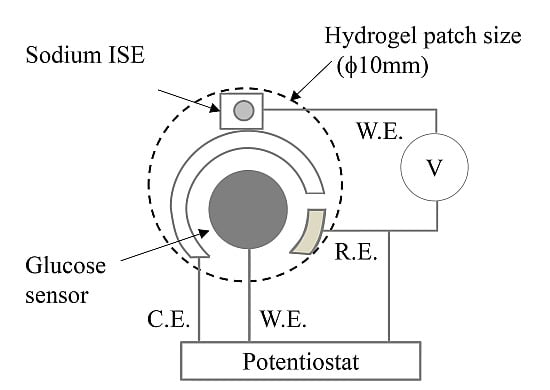
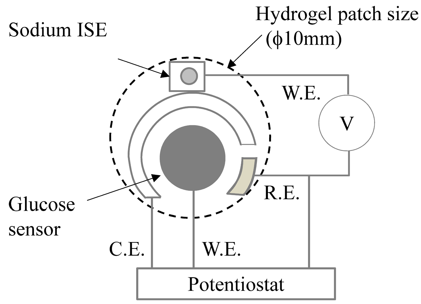
The glucose sensor (working electrode ϕ = 4 mm) and sodium ISE (working electrode ϕ = 2 mm) were positioned to measure the hydrogel (ϕ = 10 mm) (
Figure 1). One reference electrode (Ag/AgCl ink) was used for both the glucose sensor and sodium ISE. The chronoamperometric measurements of the glucose sensor and the potentiometric measurements of the sodium ISE were performed using a potentiostat (Als832a, BAS) and a digital multimeter (PC20, Sanwa Electric Instrument, Tokyo, Japan), respectively. For the glucose sensor, the applied potential was set to +0.45 V
versus the Ag/AgCl reference electrode. The room temperature was kept at 25 °C during measurements. Both sensors were immersed for 1–2 h in 268 mM KCl solution for conditioning and stabilizing the background currents.
Figure 1.
Scheme of the glucose and sodium ion sensors. ISE: ion-selective electrode; W.E.: working electrode; R.E.: reference electrode; C.E.: counter electrode.
Figure 1.
Scheme of the glucose and sodium ion sensors. ISE: ion-selective electrode; W.E.: working electrode; R.E.: reference electrode; C.E.: counter electrode.
2.3.2. Preparations of Hydrogels
Standard hydrogels were prepared by immersing hydrogels into solutions. Components of these solutions are listed in
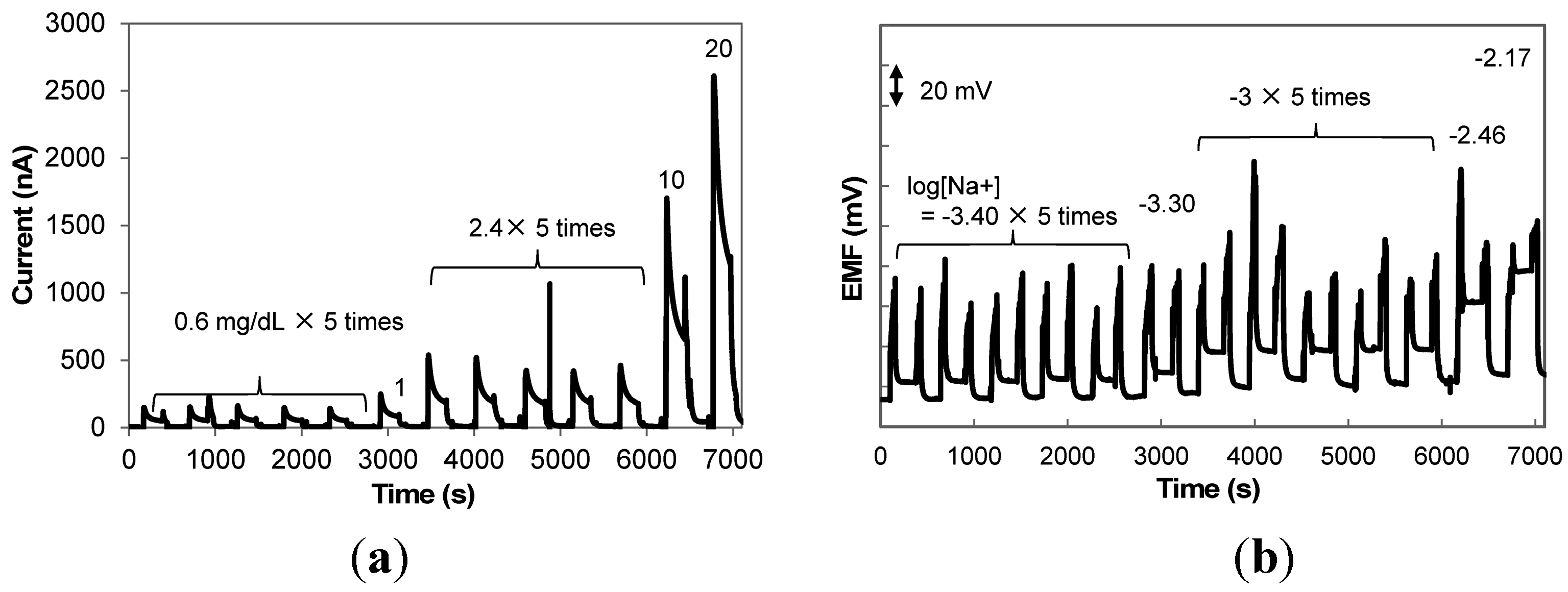
Table 1. We prepared six types of standard hydrogels, three of which (Gel No. 1, 3, and 6) were used for calibration curve fitting, and the others (Gel No. 2, 4, and 5) were used to evaluate the accuracy and precision of the estimated glucose and sodium ion levels. Other gels (Gel ID: Washing) were used to wash the surfaces of the sensors after the measurement of the levels of Gels No. 1–6. The level range was determined from previous clinical studies [
4,
5,
6], and we set four measurement points between the highest and lowest levels. For each hydrogel, 2.25 mL of immersing solution was prepared. The hydrogels were separated from the adhesive tape of the hydrogel patch used for MIET [
4,
5] and placed in the immersing solutions for at least 1 day.
Table 1.
Composition of the immersion solution for hydrogels.
Table 1.
Composition of the immersion solution for hydrogels.
| Gel ID | No. 1 * | No. 2 | No. 3 * | No. 4 | No. 5 | No. 6 * | Washing |
|---|
| Glucose (mg/dL) | 0 | 0.6 | 1 | 2.4 | 10 | 20 | 0 |
| NaCl (mM) (log[Na+] (M)) | 0.1 (−4.00) | 0.4 (−3.40) | 0.5 (−3.30) | 1 (−3.00) | 3.5 (−2.46) | 6.8 (−2.17) | 0 |
| KCl (mM) | 268 | 268 | 268 | 268 | 268 | 268 | 268 |
2.3.3. Hydrogel Measurement Protocol
The standard gel (
Table 1, Gel ID: No. 1–6) was taken out of the immersion solution, and placed on the surface of a glucose sensor and sodium ISE. Then, the gel was continuously pressed by a push–pull gauge (AP-30N, Attonic, Aichi, Japan) fixed to a desktop robot arm (V2200, SAN-EI TECH, Chiba, Japan) to stabilize the baseline current of the glucose sensor and the baseline potential of the sodium ISE. After stabilizing the sensors, the gel for measurement was placed on the push–pull gauge, and the robot arm was lowed until the gauge sensed 1 N. The measurement time was 3 min after the attachment of the gel to the sensors. For the gel washing procedure, we used gels that did not contain glucose and sodium ions (
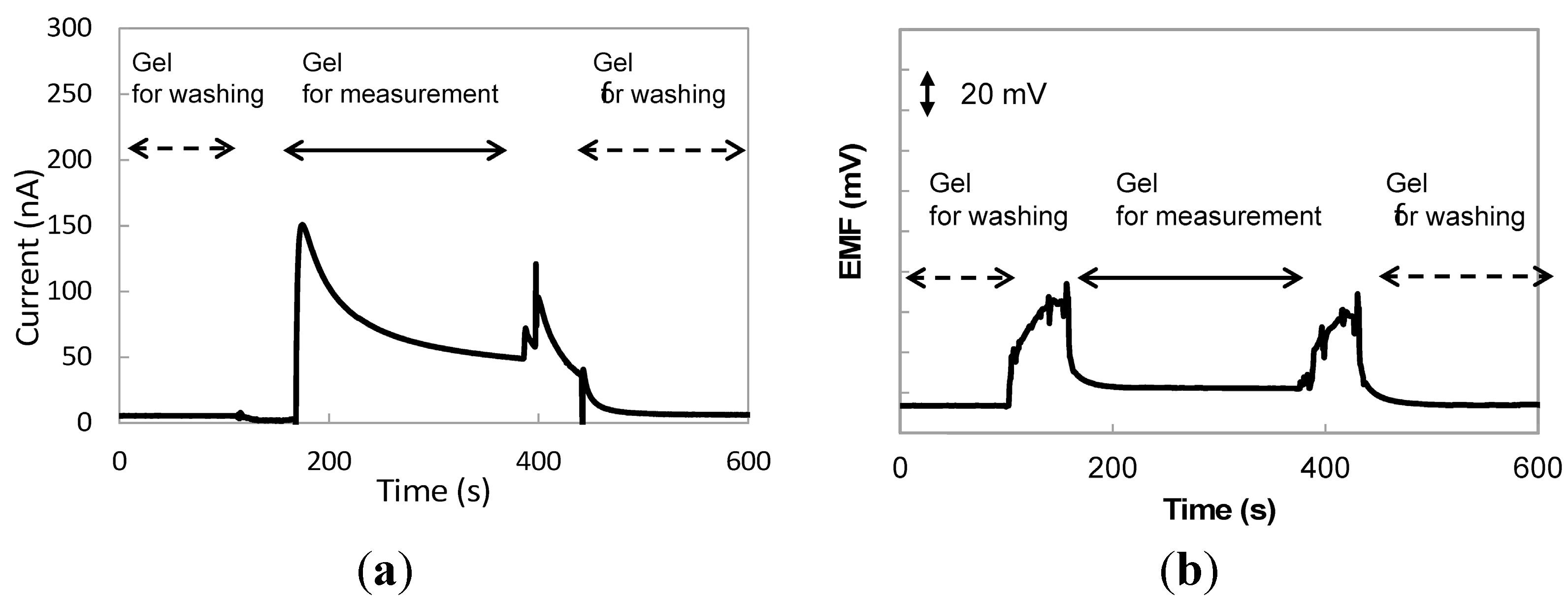
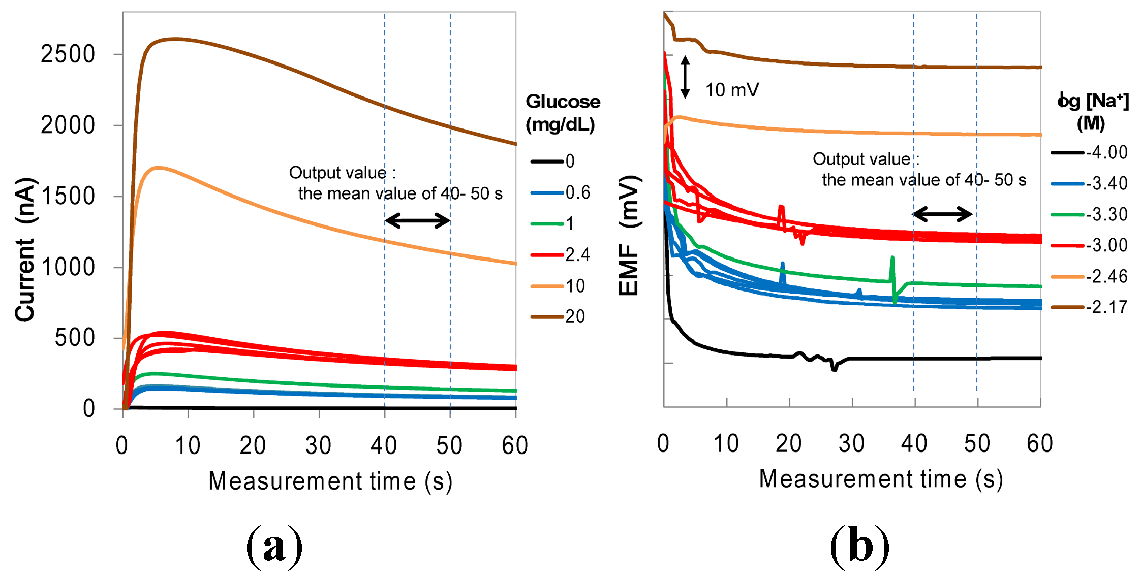
Table 1, Gel ID: washing). After 3 min measurement of a standard gel, a washing gel was placed on the surface of the glucose sensor and sodium ISE and was pressed in the same manner as for the measurement of standard gels. Representative response time curves for the glucose sensor and sodium ISE are shown in
Figure 2.
Figure 2.
Representative response time curves during gel measurements. (a) Glucose sensor and (b) sodium ISE.
Figure 2.
Representative response time curves during gel measurements. (a) Glucose sensor and (b) sodium ISE.
2.3.4. Data Analysis
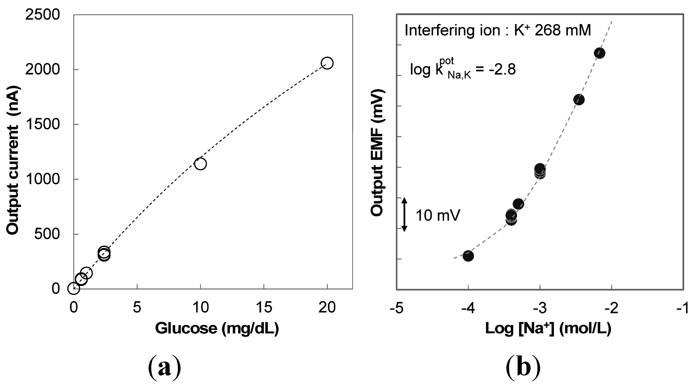
The average signals from 40 to 50 s after attaching the gel to the sensors were defined as the output values. The apparent Michaelis–Menten constant
is generally used to evaluate the biological activity of immobilized enzymes (Equation (1)) [
14,
15]. In this study, the output current from gel measurement was proportional to the steady–state current
Iss (correlation coefficient:
r = 0.999). Thus, the glucose sensor calibration curve was determined as follows (Equation (2)):
where
Iss is the steady–state current,
Imax is the maximum current measured under glucose saturation,
Cglu is the concentration of glucose and
is the apparent Michaelis–Menten constant [
14,
15].
where a is
a constant coefficient.
For the electromotive force (EMF) of sodium ISE, we used the Nicolsky–Eisenman Equation (Equation (3)):
where
CNa is the concentration of sodium ions,
CK is the concentration of potassium ions (268 mM), and
and
const are constant coefficients.
Using the data from gel calibration measurements, the calibration curve coefficients I
max/
a,
(Equation (2)) and
and
const (Equation (3)) were determined using the least-squares method. Estimated glucose levels and sodium ions levels were calculated from Equations (4) and (5):


