Article

Spurious-Free Shear Horizontal Wave Resonators Based on 36Y-Cut LiNbO3 Thin Film

1
School of Information Science and Technology, ShanghaiTech University, Shanghai 201210, China
2
Shanghai Institute of Microsystem and Information Technology, Chinese Academy of Sciences, Shanghai 200050, China
3
University of Chinese Academy of Sciences, Beijing 100864, China
*
Author to whom correspondence should be addressed.
Micromachines 2024, 15(4), 477; https://doi.org/10.3390/mi15040477
Submission received: 16 February 2023 / Revised: 27 April 2023 / Accepted: 28 April 2023 / Published: 30 March 2024
(This article belongs to the Special Issue Design, Fabrication and Testing of MEMS/NEMS, 2nd Edition)

Abstract

:
This article presents lithium niobate (LiNbO3) based on shear horizontal (SH0) resonators, utilizing a suspended structure, for radio frequency (RF) applications. It demonstrates the design, analysis, and fabrication of SH0 resonators based on a 36Y-cut LiNbO3 thin film. The spurious-free SH0 resonator achieves an electromechanical coupling coefficient ( k t 2 ) of 42.67% and a quality factor (Qr) of 254 at the wave-propagating orientation of 0° in the 36Y-cut plane.

1. Introduction

For the next generation of mobile handsets, cognitive radios, and Internet of things, radio frequency (RF) front ends need high functionality and flexibility simultaneously, within the limited RF spectrum [1,2]. The implementation of piezoelectric resonators, particularly surface acoustic wave (SAW) and bulk acoustic wave (BAW) resonators, favor a technology framework that can provide high performance for different applications [3,4]. The use of DC-DC converters with a piezoelectric resonator as the only energy-storage element has demonstrated the need for a high electromechanical coupling coefficient k t 2 and for spurious-free modes. Spurious-free modes can improve the operating range of DC–DC converters [5]. The k t 2 is proportional to the voltage-conversion efficiency [6]. The spurious modes near the pass-band remain a major challenge as they lower the k t 2 of the intended resonance and create in-band ripples and out-of-band spurious responses in filter applications [7].
Many piezoelectric devices have been investigated, such as surface acoustic wave (SAW) devices, thin-film bulk acoustic resonators (FBARs), and laterally vibrating resonators (LVRs). In recent decades, these resonators, which are based on different kinds of piezoelectric material, including aluminum nitride (AlN) [8,9], lead zirconate titanate (PZT) [10,11], doped AlN [12,13,14,15], and lithium niobate (LiNbO3) [16,17,18], have attracted wide research interest. Among these platforms, AlN FBARs have demonstrated 7% k t 2 [19], but it is challenging to implement multiple wide resonant frequencies on the same chip with FBARs because of the thickness extensional mode. Furthermore, SAW devices cannot be integrated into CMOS processes and have limited scalability for higher frequencies over 3 GHz due to their low acoustic velocity [1]. The low piezoelectric constant of AlN limits the maximum k t 2 to approximately 6% [20]. Recently, Sc-doped aluminum nitride (AlScN) was studied to improve the piezoelectric constant of AlN. A 24% Sc-doped two-dimensional resonant-rod resonator achieved a k t 2 of 23.9%, but it had a low quality factor, of 101 [21]. A relatively high Sc concentration of up to 43% can help enhance the k t 2 , but the structure of AlScN loses all its piezoelectric properties close to 60% Sc [22]. Additionally, high Sc concentrations can also cause high density in anomalously oriented grains, which causes k t 2 and Q degradation [23,24].
Unlike FBARs and SAW devices, LVRs can cover multiple frequencies on the same wafer, and are also compatible with the CMOS process. The LVRs leveraging transferred LiNbO3 thin films have been developed to feature higher k t 2 and Q at the same time. The LiNbO3 LVRs based on various acoustic modes, including symmetric (S0), shear horizontal (SH0), and first-order antisymmetric (A1) modes, have exhibited extraordinarily high k t 2 (>20%) and Q of up to several thousand at RF [7,24,25,26,27,28,29,30]. Despite their impressive performance, these devices have not fully harnessed their pronounced piezoelectric properties due to the spurious response in LiNbO3 resonators. The spurious response originates from various kinds of unwanted mode. It will be challenging to fully utilize the piezoelectric properties of LiNbO3 to achieve resonators with large k t 2 and Q. In particular, the in-band ripples caused by the spurious mode adjacent to the intended mode make it difficult to obtain the maximum bandwidth and minimum insertion loss simultaneously. Therefore, the suppression of these spurious modes is of great significance for the application of LiNbO3 LVRs. Recently, a few studies focused on the origin and suppression of spurious modes in LiNbO3 LVRs. Suppression techniques for spurious modes have been developed using modified edge shapes [31], length-controlled electrode configurations [1] and 2-electrode-array designs [32] in SH0 LiNbO3 LVRs, and weighted electrode configurations in S0 LiNbO3 LVRs [33], as well as the method based on the recessed electrodes in LiNbO3 A1 resonators [34].
Specifically, this paper investigates the shear horizontal modes of 0-order (SH0) in thin plates of 36Y-cut LiNbO3 to determine the trade-offs between different resonator-structure parameters in order to suppress the spurious response and improve the k t 2 . The 36Y-cut was selected because it has a major advantage in terms of the piezoelectric stress coefficient e16 compared with other orientations of LiNbO3 [1,24,35,36,37]. It can help excite the SH0 mode with its large electromechanical coupling coefficient. Additionally, most studies on SH0 resonators have focused on the X-cut because it is more readily available from wafer vendors, and it can also couple with other vibration modes easily [1,31,36,38,39]. A few studies on SH0 resonators based on 36Y-cut lithium niobate on an insulator (LNOI) focused on temperature-stability analysis [18,40]. Among the different modes of Lamb wave resonator, the 0-th-order shear horizontal (SH0) mode possesses the highest k t 2 . However, few examples exist in the literature that make full use of the advantages of 36Y-cut LiNbO3 to achieve a k t 2 of more than 40% and spurious-free modes simultaneously. In this work, we explore the impact of various geometrical parameters, such as the pitch, length, and width of the IDT electrodes on the k t 2 of a SH0-mode resonator in 36Y-cut LiNbO3 and demonstrate passband spurious-free devices, with a highest achieved k t 2 of 42.6%. In addition, the influence of the electrode parameters on the suppression of the spurious modes is also discussed. Finally, spurious-free LVRs with high k t 2 , which we fabricated in this study, are characterized.

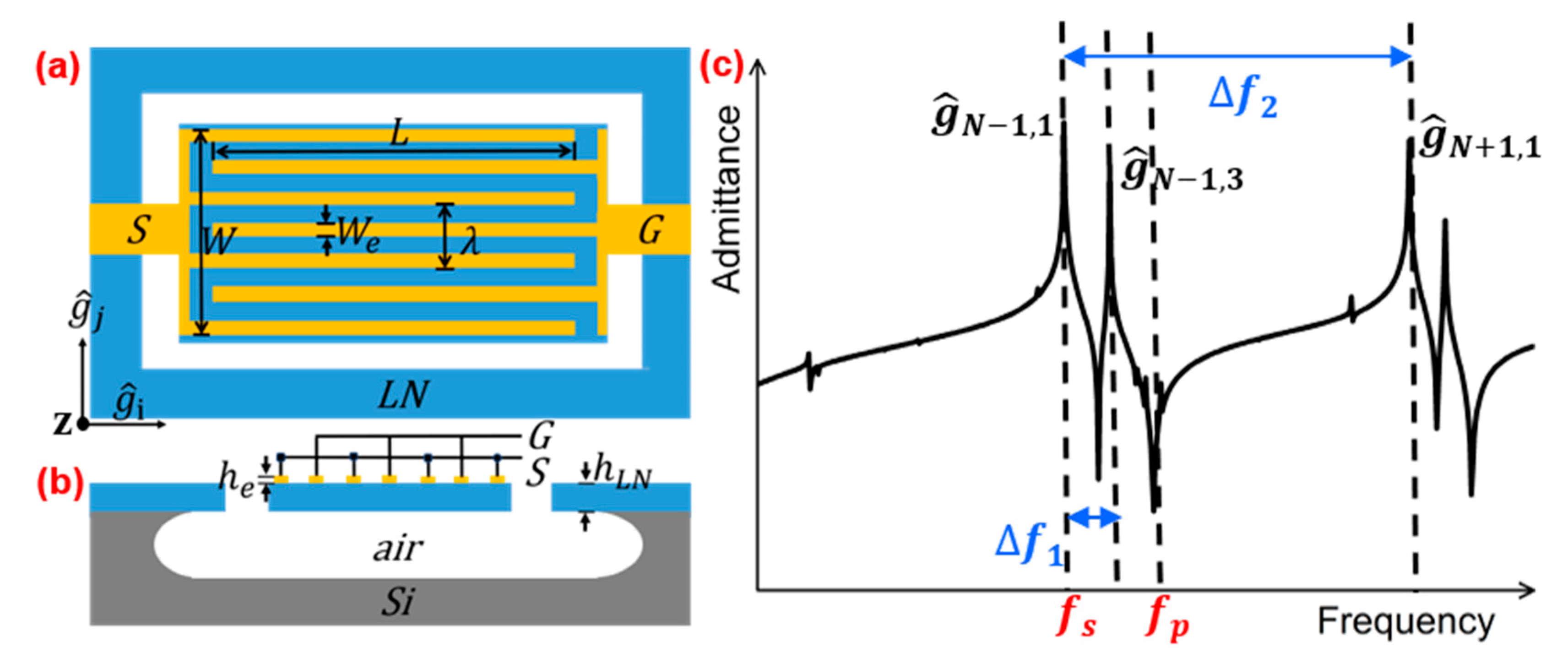
2. Design and Analysis

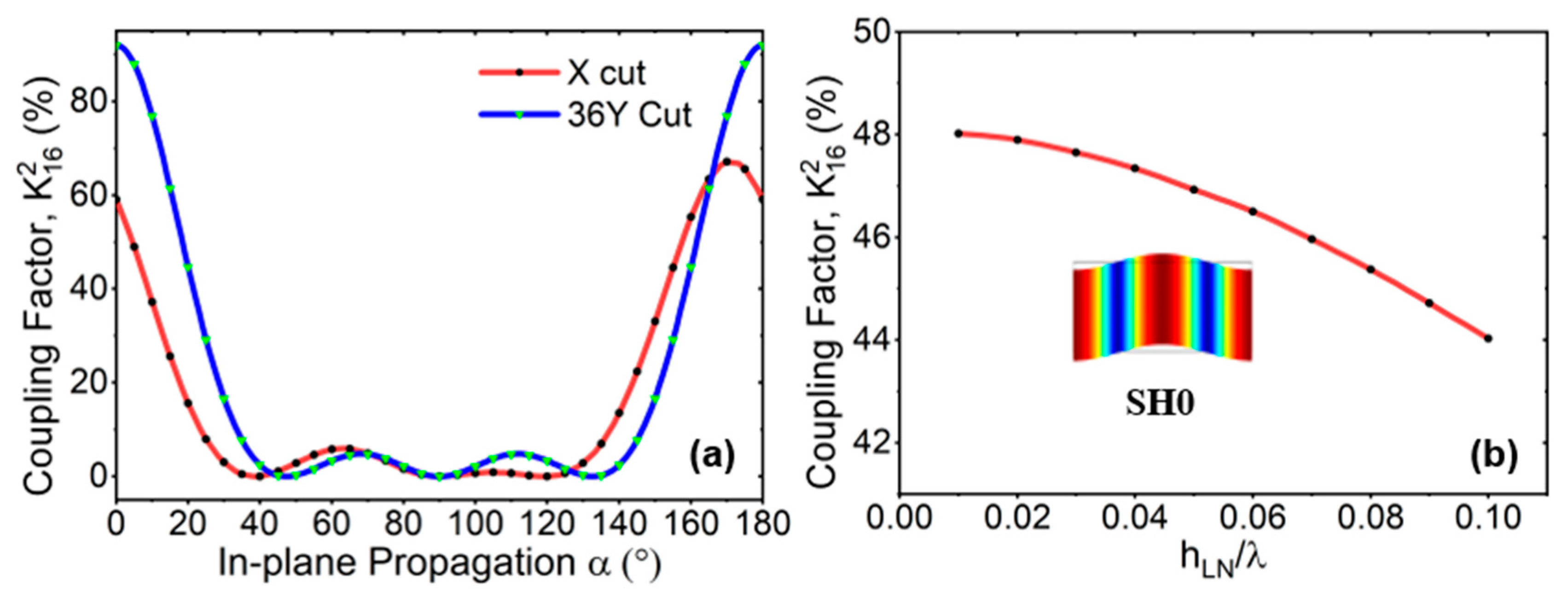
2.1. Excitement of SH0 Mode in LiNbO3

In this work, SH0 mode is focus because of the largest intrinsic electromechanical coupling factor ( K i j 2 ) in LiNbO3 for this particular mode and low velocity dispersion over a wide range of film thicknesses [41]. The 36Y-cut LiNbO3 has a large piezoelectric-stress-constant component of −4.48 (C/m2) in e16, which can excite shear horizontal mode effectively [42]. The complete rotated e-matrix for 36Y-cut LiNbO3 is as follows [17]:
e = 0 0 0 1.65 2.30 2.57 1.94 1.59 4.53         0 0.12 4.48 0.47 0 0 0.26 0 0   C / m 2
To quantitatively compare different orientations, the electromechanical coupling K i j 2 is studied under a quasi-static approximation, where i is the electric field direction and j is the stress component. Figure 1a shows K 16 2 versus in-plane-propagation direction α for the SH0 mode based on X and 36Y cuts. Compared with commonly used X-cut [1,24,35,36,37], 36Y-cut has larger K 16 2 . Here, the Euler rotated angle is (α, 54, 0) for 36Y-cut. The electrode-arrangement direction is along the x-axis direction after Euler rotation, and α represents the in-plane direction of wave propagation. The K i j 2 is defined as follows [43]:
K i j 2 = e i j 2 / ε i i T × s j j E
where e is the piezoelectric coefficient, ε T is the permittivity under constant stress, and s E is elastic compliance under constant electric field. Obviously, when α is around 0, the K 16 2 of the SH0 mode is extremely high. Therefore, SH0 mode can be excited efficiently in this case. Based on these results (i.e., α = 0 ° ), Figure 1b presents the K 16 2 of SH0 with the different normalized LiNbO3 thickness (hLN/ λ ) within 0.1 (wavelength λ equals twice pitch of IDT). The K 16 2 of SH0 mode gradually decreases as the hLN/ λ increases. Here, K 16 2 ( K 16 2 = v p 2 v s 2 / v s 2 ) is calculated using the velocities of the same acoustic mode under the open ( v p ) and short ( v s ) conditions. The vibration-mode shape of SH0 is also shown in Figure 1b.

2.2. Suppression of High-Order SH0 Spurious Mode

The SH0 wave on the bulk material leaks into the substrate, which can be mitigated by utilizing a suspended thin-film structure [44]. Several studies of the suppression of spurious modes focused on piezoelectric resonator [45], where longitudinal and transverse indicate the direction along and perpendicular to the propagation direction. The top view and cross-section view of conventional electrode configuration for SH0 resonator are shown in Figure 2a,b. Here, W and L are the width and length of the suspended plate, respectively. The We, Wp, and λ represent the width of the electrode, pitch, and the wavelength, respectively. Neglecting the in-plane an-isotropic, the resonant frequencies of all the acoustic modes in a plate can be expressed by:
f i , j = v 0 ' g ^ i , j 2 π = v 0 ' i 2 W 2 + j 2 L 2
g ^ i , j = g ^ i + g ^ j
where i and j are the wave vectors of the longitudinal and transverse modes and v 0 ' is the phase velocity of the acoustic wave. For a device with N electrodes, g ^ N 1 , 1 is the desired main mode. In operation, electric fields introduced by the top electrode induce periodic strain and stress fields, forming acoustic modes of various orders, as depicted in Figure 2c [24]. To form spurious-free filters, the nature of spurious modes in a typical LiNbO3 LVR needed to be investigated first, before spurious-mode-mitigation feature could be developed.
To visualize the displacement of shear horizontal modes of various orders, COMSOL finite element analysis (FEA) was used to simulate the eigenmodes in 3D LiNbO3 modes (Figure 3a). Various SH0 shape modes of g ^ 1 , 1 , g ^ 1 , 3 , g ^ 3 , 1 and g ^ 3 , 3 are shown, with a mode order denoting the number of half-wavelength periodicities in the longitudinal and transverse directions.

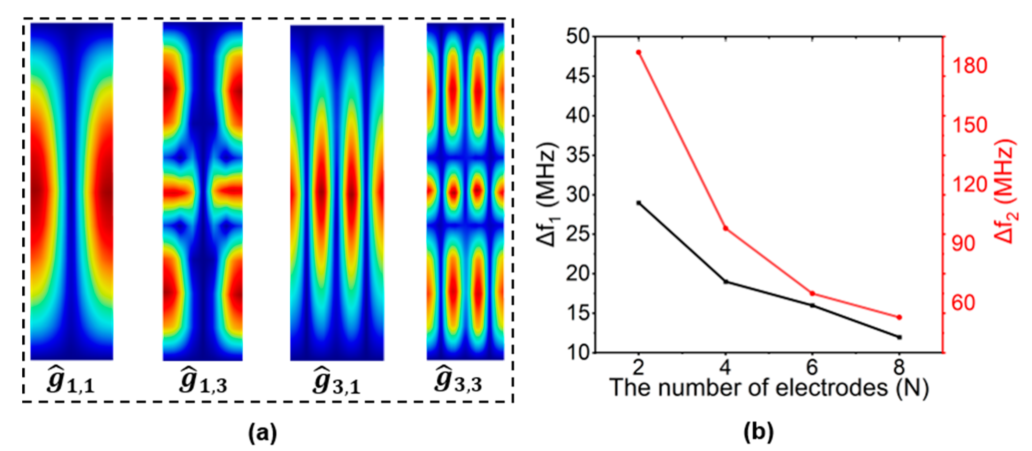
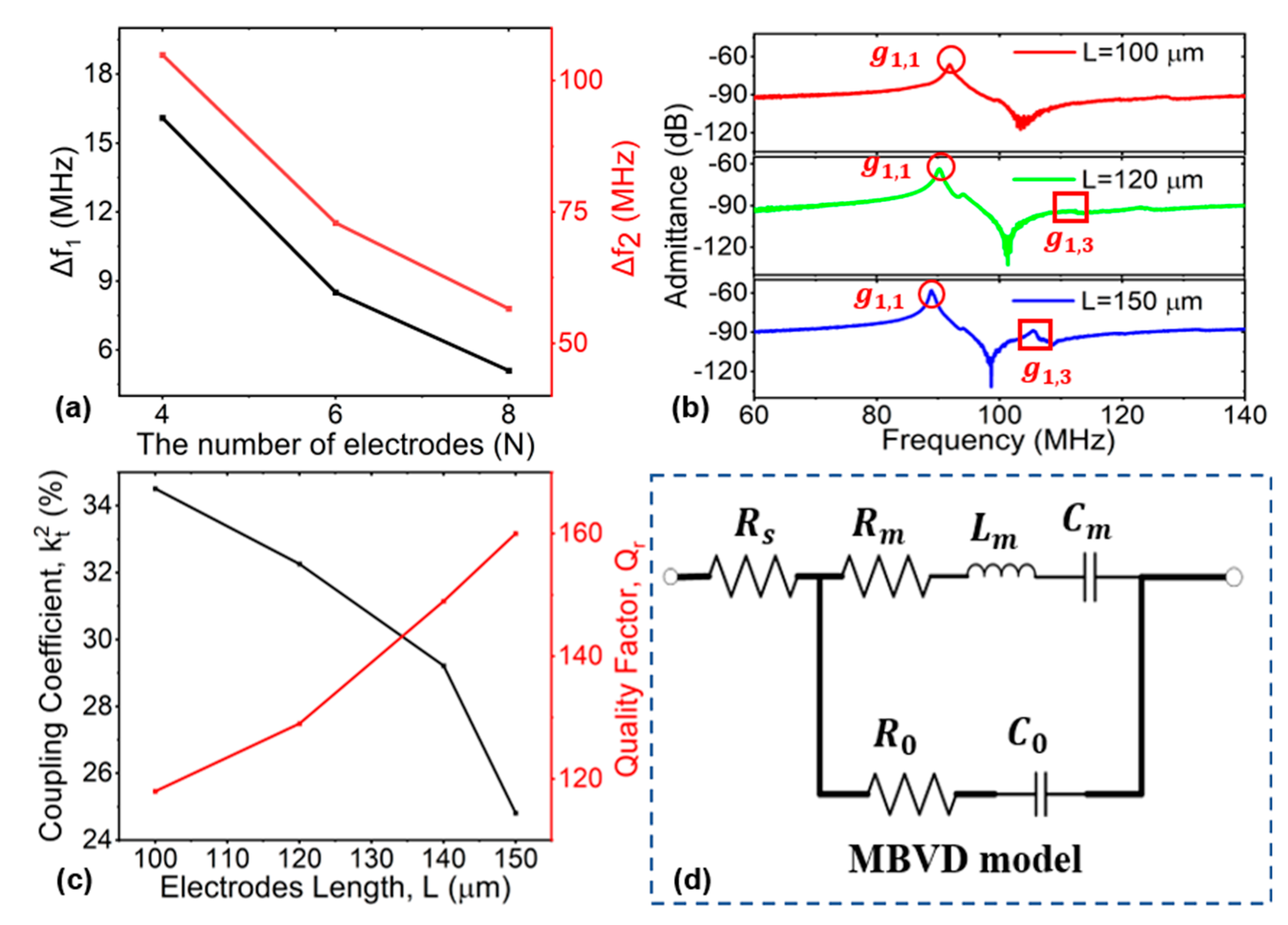
2.2.1. The Number of Electrodes (N)

For a resonator with a particular number of electrodes (more than 2), spurious modes occur at various frequencies. When the number of electrodes increases, the higher-order transverse ( g ^ N + 1 , 1 , g ^ N + 3 , 1 ) and longitudinal ( g ^ N 1 , 3 , g ^ N 1 , 5 ) modes are often positioned closer to the desired mode ( g ^ N 1 , 1 ). The minimum number of interdigitated electrodes (N = 2) would make the value of f 1 and f 2 reach maximum ( f 1 and f 2 represent the frequency gap between the fundamental mode g ^ N 1 , 1 and high-order longitudinal mode g ^ N 1 , 3 , the fundamental mode g ^ N 1 , 1 , and high-order transverse mode g ^ N + 1 , 1 , respectively), as shown in Figure 3b. This can contribute to distancing and attenuating higher transverse and longitudinal modes, and it can also create a large spurious-free range for comprising filters. Consequently, the main mode distances from and attenuates higher-order longitudinal and transverse modes to the greatest extent when the number of electrodes N = 2, creating the largest spurious-free space.

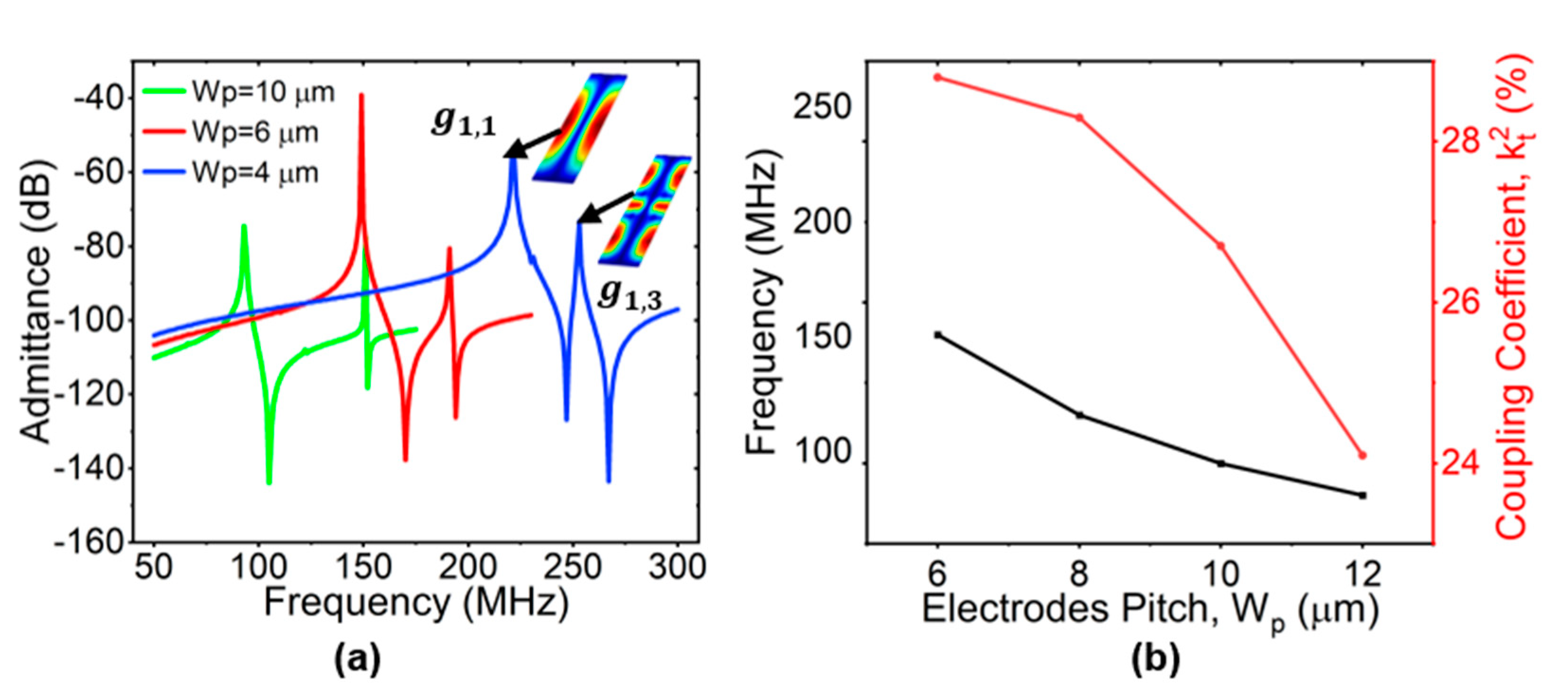
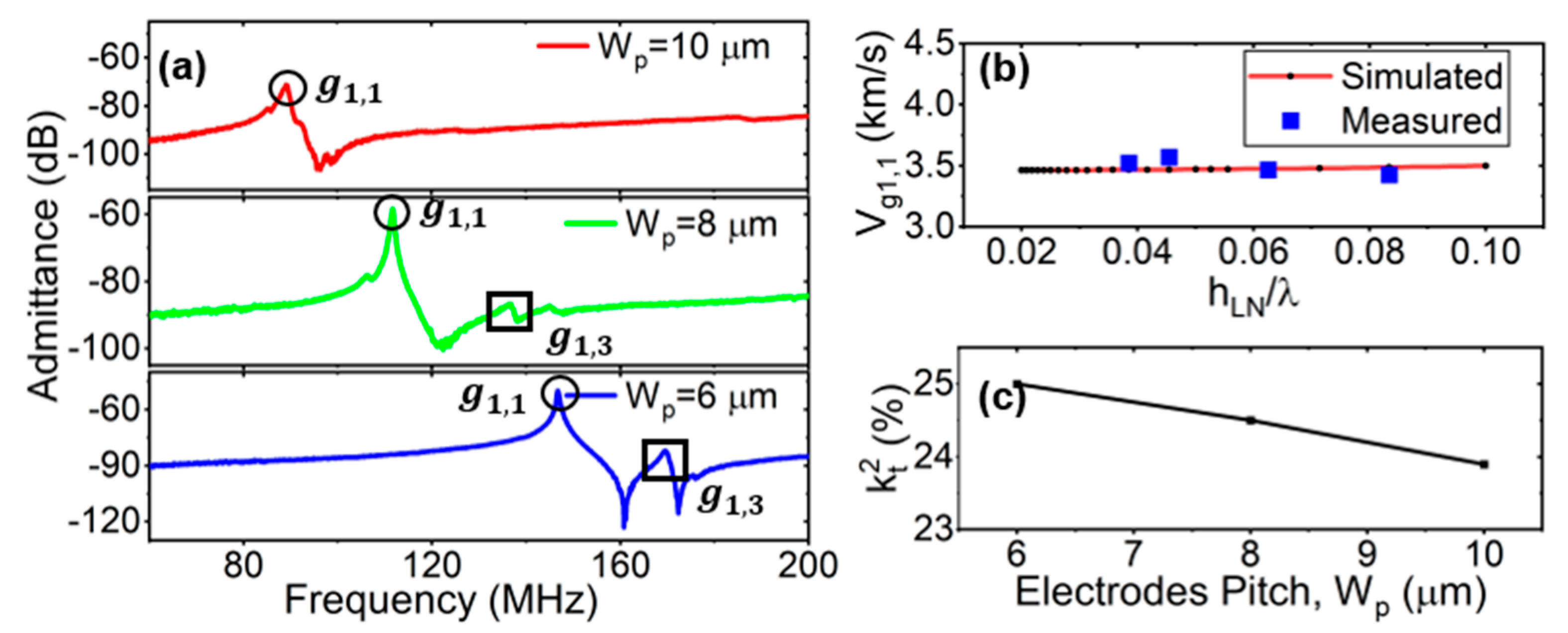
2.2.2. The Pitch of Electrodes (Wp)

The simulated admittance curves with different pitches are shown in Figure 4a, where electrodes are N = 2, hLN = 0.75 µm, L = 100 µm, he = 0.2 µm, and We/Wp = 50%. The g ^ 1 , 1 and g ^ 1 , 3 are labeled on the curve when Wp = 10 µm, as an example. As expected, as the pitch increased, g ^ 1 , 3 is moved far away from the desired g ^ 1 , 1 . Considering the fabrication accuracy and the suppression of the parasitic mode, Wp = 10 µm was selected for the subsequent analysis. The simulated variations of frequency and k t 2 with Wp are shown in Figure 4b. They both increased significantly when Wp decreased. Larger Wp values led to smaller frequency and k t 2 , but spurious-free modes. In the early stage, the k t 2 was derived from the thickness mode, and the value was close to the definition of K i j 2 [46]. Next, the expression of k t 2 was improved by fitting the measured value according to the Butterworth Van Dyke (BVD) model, which was applicable to laterally vibrating piezoelectric resonators [47]. The k t 2 is defined using the series ( f s ) and parallel ( f p ) resonant frequency [48]:
k t 2 = π 2 8 f p 2 f s 2 f s 2

2.2.3. The Lengths of Electrodes (L)

The 3D COMSOL FEA was used to analyze the suppression of transverse modes based on different electrodes’ lengths. We set We/Wp = 50%, Wp = 10 μ m . The values of the simulated k t 2 of the g ^ 1 , 1 mode at different electrode lengths L are shown in Figure 5a. The k t 2 was negatively correlated with the electrode length, indicating that longer L caused lower k t 2 . This can be explained by the fact that higher-order acoustic waves can be scattered from the resonant cavity in the transverse direction, thereby eliminating the spurious mode and improving k t 2 of fundamental mode when L decreases [31]. Figure 5b presents a no-dimensional analysis of the ratio of f 1 / f 1 , 1 and f 1 / f 1 , 3 with different Wp/L. The f 1 was the same at fixed Wp and L, but f 1 , 1 and f 1 , 3 were different. As L gradually increased or Wp gradually decreased, the curves of f 1 / f 1 , 1 and f 1 / f 1 , 3 gradually overlapped. This indicates that the f 1 , 1 and f 1 , 3 were becoming closer, which also meant that the influence of the spurious mode on the main mode increased. The ratio of f 1 and f 1 , 1 or f 1 , 3 was related to W p / L , which can be explained by Equation (3). In conclusion, larger L not only caused lower k t 2 in g ^ 1 , 1 , but it also led to a tighter frequency gap between g ^ 1 , 3 mode and desired mode g ^ 1 , 1 , which probably led to spuriousness in passband. Larger L also had more spurious modes and lower k t 2 .
In general, a resonator with a minimum number of interdigitated electrodes (N = 2) would attenuate higher-order spurious modes and create a larger spurious-free tuning range for wideband oscillators and RF filters. However, a single two-electrode resonator would have a very small static capacitance (C0) in comparison to the feedthrough or parasitic capacitance (Cf) between probing pads [49]. The measured results of single resonators typically produce high rates of uncertainty, particularly when C0 is smaller than Cf. To attain a higher static capacitance (C0) for better impedance matching, an array of parallel-connected two-electrode resonators can be employed [48,50].

3. Fabrication and Measurement Results

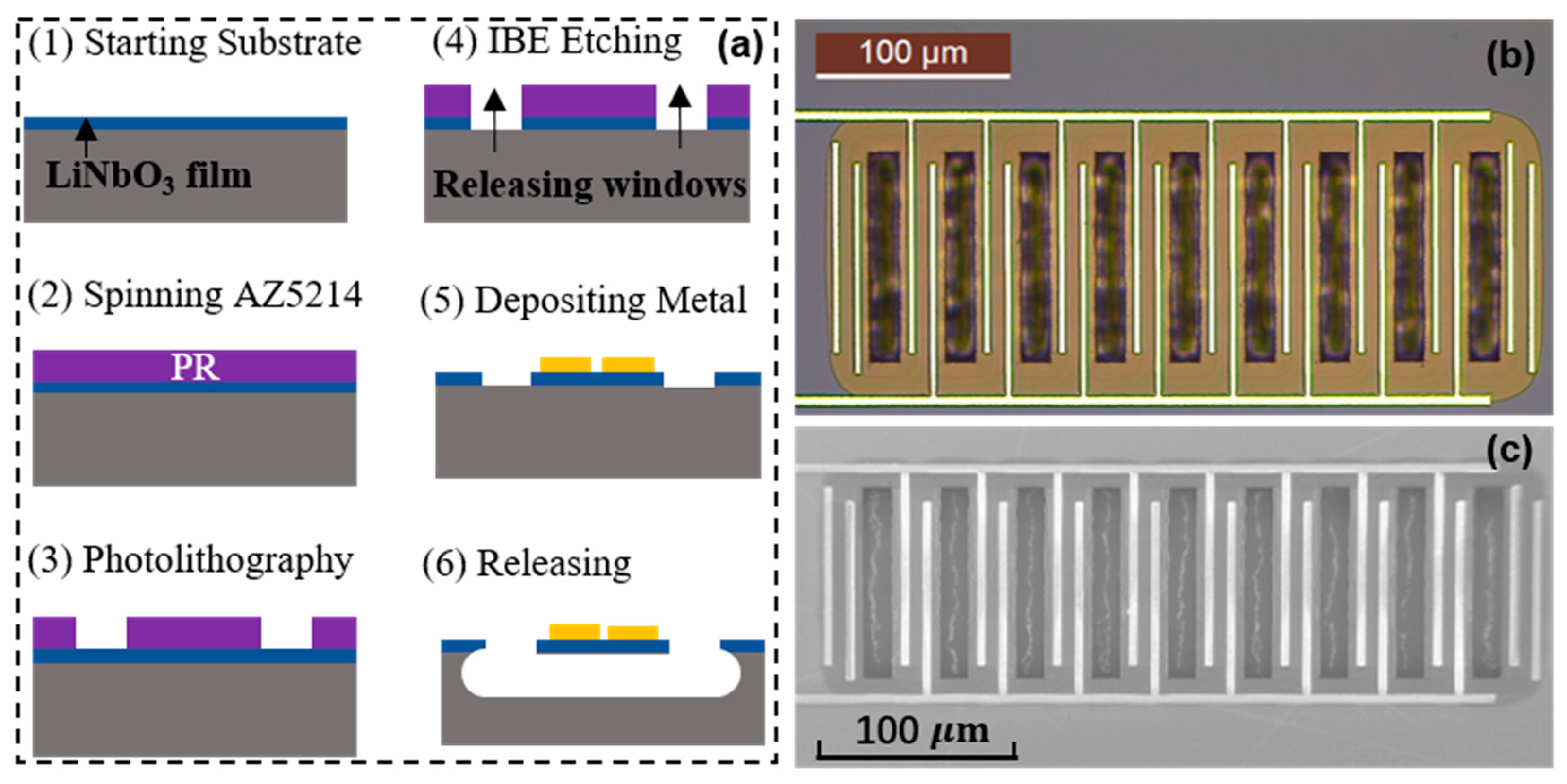
3.1. Fabrication Process

Figure 6a shows the fabrication process of the LiNbO3-film resonator for SH0 modes. Firstly, a 36Y-cut LiNbO3 film 0.75 μm in thickness was transferred onto a high-resistivity Si wafer. The film was procured from Fluoroware (now part of Entegris). Before the ion-beam etch (IBE) process, hard baking (115 °C for 10 min) was performed on the AZ5214 to harden the photoresist (PR) to serve as the mask for the etching of the LiNbO3.
A bias voltage of 300 V was used in the IBE-etching process, and the etching rate was approximately 13 nm/min [51]. In addition, the temperature variation in the whole process was minimized to avoid thermal stress. Next, the photoresist mask (AZ5214) was removed with Piranha, and 10 nm Ti and 200 nm Al were subsequently defined on top of the LiNbO3 thin film as the IDT electrodes, using a lift-off process. To suspend the resonator structure, the Si under the LiNbO3 devices was removed with XeF2-based isotropic dry etching.
One of the fabricated LiNbO3 SH0 devices is shown in Figure 6b,c. The L of the fabricated devices was 100 µm. Multiple groups with identical two-electrode resonators were connected in parallel to increase the C0, which tuned the impedance matching with the RF terminal. For the fabricated resonator, the dummy electrodes were implemented on the edges of the resonators to ensure that the structure was symmetrical and that identical resonances were obtained for all the parallel resonators [32].

3.2. Measured Results and Discussion

3.2.1. Measurement Analysis of N and L

The S-parameter data of the one-port LiNbO3 LVRs were measured by a network analyzer (Keysight N5234B). The feedthrough capacitances of the signal-grounding probing pads and routing connection were responsible for lowering the experimentally observed k t 2 . Thus, the extraction of accurate k t 2 from the results measured from a single resonator requires the de-embedding of the feedthrough or parasitic capacitance [49]. The S-parameter matrix was converted to a Y-parameter matrix to extract the admittance of the device under test (DUT), and the net admittance of the resonator was then obtained by de-embedding the open structure on the same chip from the DUT [52]. The measured frequency gaps of the f 1 and f 2 with different electrode numbers Ns are shown in Figure 7a. The lower N contributed to larger spurious-free frequency gaps, which was consistent with the simulated results shown in Figure 3b. Lower N values also caused lower excitement efficiency in the g ^ 1 , 3 ; therefore, the g ^ 1 , 3 mode was not present in the measured admittance at N = 2. The measured admittance responses with L = 100 µm, 120 µm, and 150 µm are shown in Figure 7b. With the electrodes’ lengths L increasing, g ^ 1 , 3 approached the desired g ^ 1 , 1 , and the excitement efficiency of the spurious mode g ^ 1 , 3 also increased. The measured k t 2 and Qr with different L values are shown in Figure 7c,d. Larger L values also increased the quality factor Qr, which can be explained by the fact that the vibrational energy was better confined within the resonator body, and little escaped through the anchors [30]. However, the coupling coefficient k t 2 decreased with increases in electrode length L.
The k t 2 of the resonator can be calculated by identifying fr and fp using Equation (5), in line with common practice. The k t 2 can be alternatively extracted by fitting the measured admittance with the MBVD model (Figure 7d) [53]. The model consists of the static capacitor C0, the motional resistor Rm, the motional inductor Lm, the motional capacitor Cm, and the series resistance (Rs). The Rs shows the resistance of the pads and electrodes, which is measured from test structures with shorted fingers [54]. The Rm represents the actual energy dissipation in a resonator. The Lm and Cm represent the interchangeable mechanical energy storage in a resonator, which can be expressed by referring to [8]. The quality factors (Qr) can be expressed as follows [3,24,55,56]:
Q r = f r f 3 d B
The single-resonance MBVD fitting method is reliable for extracting circuit parameters in cases of spurious-free near-the-main-mode or low-coupling resonators, in which only the resonance (fs) and antiresonance (fp) frequency peaks are fitted [3]. In this case, Qr can be accurately obtained using the ratio of the frequency to the −3 dB frequency widths of the impedance response at fr, as in Equation (6).

3.2.2. Measurement Analysis of Wp

The device’s frequency responses as a function of pitches Wp are shown in Figure 8a. The main mode g ^ 1 , 1 and the spurious mode g ^ 1 , 3 near the main mode are labeled on the curves when Wp = 6 µm, 8 µm, and 10 µm, respectively. Similar to the simulated results shown in Figure 4, the interval between g ^ 1 , 3 and g ^ 1 , 1 increased when the Wp increased. Figure 8b shows the comparison with the simulated and measured phase velocity of the LVRs based on the 36Y-cut LiNbO3. The measured data were extracted through RF measurement. The phase velocity of the LiNbO3 operating in the g ^ 1 , 1 SH0 mode was about 3500 m/s. The operating frequency of the resonators was changed by varying the designed devices’ wavelengths. Although increases in the Wp suppressed the spurious modes of the devices, this eventually led to decreases in k t 2 , as shown in Figure 8c.

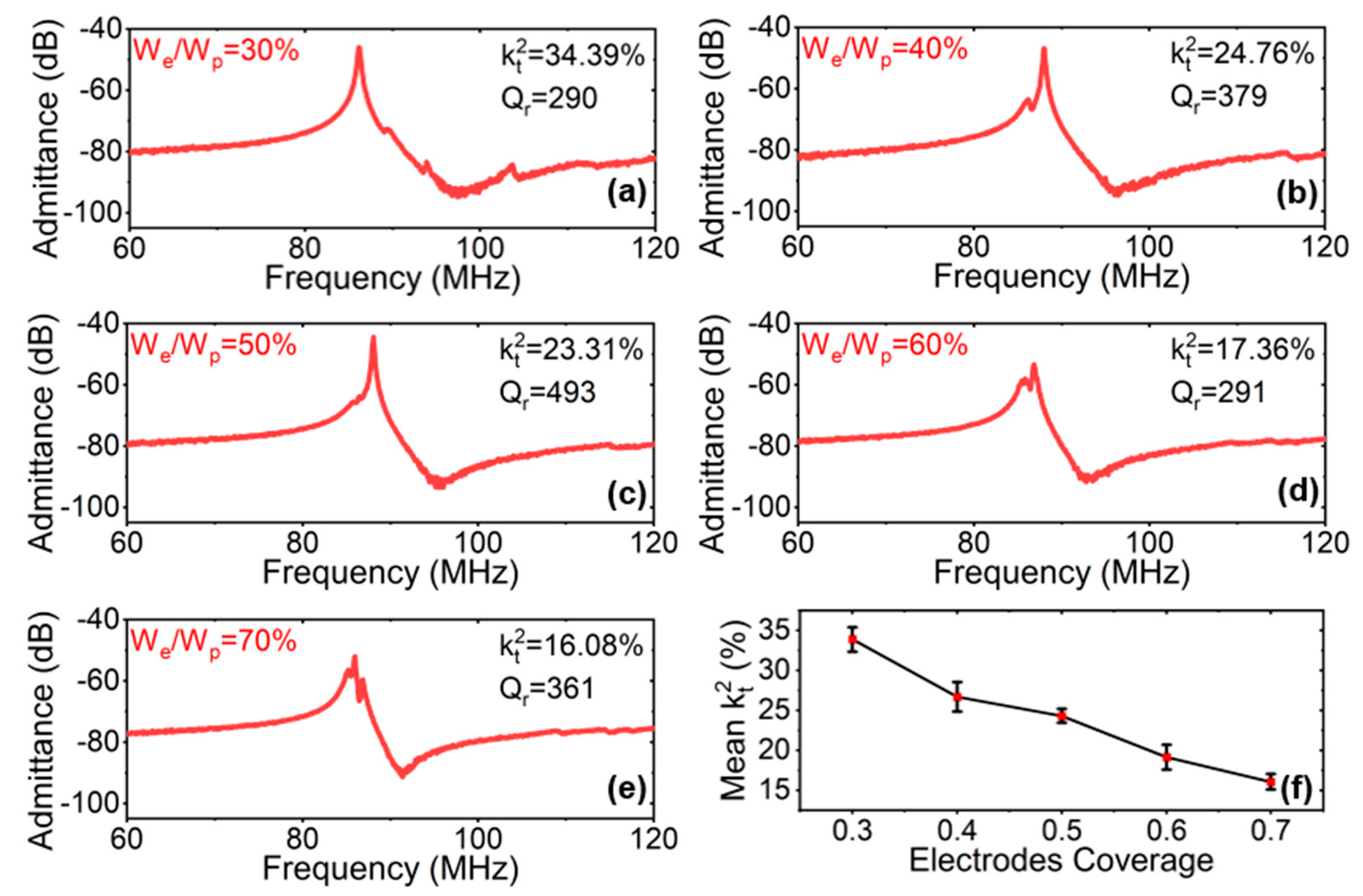
3.2.3. Measurement Analysis of Electrode Coverage (We/Wp)

Coverage can directly affect the capacitance per unit area under a given wavelength. Increases in this parameter facilitate the fabrication of more compact devices and reduce the need for arraying large numbers of resonators [57,58]. The k t 2 depends on the electrode coverage (We/Wp) of the device, as it directly influences C0 and Cm. Figure 9 shows the measured admittance response and MBVD model fitting with different coverages (We/Wp). The corresponding k t 2 and resonant-quality factor Qr are marked. The increasing of We/Wp represents a reduction in the spacing between the electrodes, which caused the C0 to grow non-linearly as C 0 1 / 1 W e / W p . At the same time, due to the increase in electrode area, the Cm increased linearly with the We/Wp [54]. The k t 2 dropped gradually when the coverage increased. The device with We/Wp = 30% had the highest k t 2 . This was consistent with the analysis of electrode coverage in previous S0 resonators [58].
Five electrodes’ coverage values were investigated, and the respective Qr values were recorded (Figure 9a–e). The relationship between device We/Wp and Qr is still under investigation [57]. Figure 9f illustrates the comparison between the values of the measured mean electromechanical coupling k t 2 under different degrees of electrode coverage We/Wp. All had similar trends, in that smaller electrode coverage led to larger k t 2   values. The mean k t 2 values varied from 33.9% to 16.1%, with the We/Wp increasing from 0.3 to 0.7.
In this study, we finally explored high- k t 2 and spurious-less LVRs based on a 36Y-cut LiNbO3/Si substrate, as shown in Figure 10a,b. It is worth mentioning that the equivalent electrical MBVD model is a behavioral model, which is only valid around the resonance frequency of a modeled resonator [59]. This means that it may have infinite configurations for the same response when not considering the physical properties of the individual resonator [60]. In order to ensure that the values of the MBVD fitting were within a reasonable range, we used a Keysight Technologies B1500A semiconductor analyzer device to measure the I–V curves of the pad and the routing connection. The contact losses were used to model the series resistor Rs (~43 Ω ). Using the FEM simulation and the analysis results above, the cut angle of the LiNbO3 was optimized as 36°, and the in-plane propagation direction α was 0°. The device was designed with an electrode coverage of We/Wp = 0.3, the electrode array M = 8, and electrode length L = 100 μm. The fabricated LVRs were confirmed as having a k t 2 of 42.67% after de-embedding. The temperature coefficient of frequency (TCF) was extracted by monitoring the shift in the series-resonance frequency as a function of temperature. Temperature measurements in the range of 28 °C to 128 °C were performed. Figure 10c shows the measured TCF for the fabricated SH0 resonator device. The extracted TCF was −97.05 ppm/°C, which is larger than that of pure AlN. This is attributable to the increased thermal expansion coefficients. Further temperature-compensation techniques can be implemented to improve the device TCF. The appearance of the spurious mode between the fs and the fp is attributable to a slight variation in the mechanical boundary conditions and, thus, resonant-frequency mismatch between individual resonators in the array [55]. The spurious mode can be eliminated by improving the fabrication accuracy to ensure that each resonance unit in the array has the same response.
Finally, Table 1 provides a comparison between our work and previous thin-film LiNbO3 LVRs. The A1 resonator has a higher frequency than the SH0 with the same fabrication accuracy because the A1 mode has a greater velocity than the SH0 mode. Due to the high e16, the X-cut and 36Y-cut can both achieve high k t 2 . Although the resonators in [54] exhibited the best k t 2 , they also have multiple spurious modes in the passband. As a result, the proposed 36Y-cut LiNbO3 SH0 resonators not only feature a simple process but show a well-balanced performance in terms of k t 2 and spurious-mode suppression. Their operating frequency can be improved by fabricating electrodes with shorter wavelengths using E-beam lithography for higher-frequency applications. The fabrication process is described in [54].

4. Conclusions

In this work, we designed and analyzed the performance of a 36Y-cut LiNbO3 thin film based on resonator devices. By configuring the length and width of the IDT electrode, the transverse spurious mode g ^ 1 , 3 was suppressed efficiently. In addition, the influence of the electrode coverage on the coupling coefficient k t 2 of the SH0 mode was discussed. The method of suppressing the transverse spurious mode and the influence of the coverage on the coupling were verified by the experimental device’s fabrication and characterization. The fabricated devices achieved a peak electromechanical coupling of 42.67% and a quality factor (Qr) of 254. Future research could focus on improving the Q value of the array. Potential methods for improving the Q value of the array include the improvement of the etching sidewall and roughness, vacuum encapsulation, and addressing imperfections and non-uniformities among the elements in the array.

Author Contributions

Conceptualization, T.W.; methodology, simulation, fabrication, and analysis, Y.L. (Yushuai Liu), K.L., J.L. and Y.L. (Yang Li). All authors have read and agreed to the published version of the manuscript.

Funding

This research was funded by Lingang Laboratory under grant LG-QS-202202-05.

Data Availability Statement

Not applicable.

Acknowledgments

Authors appreciate the device-fabrication support from ShanghaiTech Quantum Device Lab (SQDL) and Soft Matter Nanofab (SMN180827).

Conflicts of Interest

The authors declare no conflict of interest.

References

  1. Song, Y.-H.; Lu, R.; Gong, S. Analysis and removal of spurious response in SH0 lithium niobate MEMS resonators. IEEE Trans. Electron Devices 2016, 63, 2066–2073. [Google Scholar] [CrossRef]
  2. Okazaki, H.; Fukuda, A.; Kawai, K.; Furuta, T.; Narahashi, S. Mems-based reconfigurable rf front-end architecture for future band-free mobile terminals. In Proceedings of the 2007 European Microwave Conference, Munich, Germany, 9–12 October 2007; pp. 1058–1061. [Google Scholar]
  3. Faizan, M.; Villanueva, L.G. Frequency-scalable fabrication process flow for lithium niobate based Lamb wave resonators. J. Micromech. Microeng. 2019, 30, 015008. [Google Scholar] [CrossRef]
  4. Nguyen, C.T.-C. MEMS-based RF channel selection for true software-defined cognitive radio and low-power sensor communications. IEEE Commun. Mag. 2013, 51, 110–119. [Google Scholar]
  5. Stolt, E.; Braun, W.D.; Gu, L.; Segovia-Fernandez, J.; Chakraborty, S.; Lu, R.; Rivas-Davila, J. Fixed-frequency control of piezoelectric resonator dc-dc converters for spurious mode avoidance. IEEE Open J. Power Electron. 2021, 2, 582–590. [Google Scholar] [CrossRef]
  6. Braun, W.D.; Stolt, E.A.; Gu, L.; Segovia-Fernandez, J.; Chakraborty, S.; Lu, R.; Rivas-Davila, J.M. Optimized resonators for piezoelectric power conversion. IEEE Open J. Power Electron. 2021, 2, 212–224. [Google Scholar] [CrossRef]
  7. Yang, Y.; Lu, R.; Gong, S. High Q Antisymmetric Mode Lithium Niobate MEMS Resonators with Spurious Mitigation. J. Microelectromech. Syst. 2020, 29, 135–143. [Google Scholar] [CrossRef]
  8. Piazza, G.; Stephanou, P.J.; Pisano, A.P. Piezoelectric aluminum nitride vibrating contour-mode MEMS resonators. J. Microelectromech. Syst. 2006, 15, 1406–1418. [Google Scholar] [CrossRef]
  9. Gong, Z.; Bruch, A.; Shen, M.; Guo, X.; Jung, H.; Fan, L.; Liu, X.; Zhang, L.; Wang, J.; Li, J. High-fidelity cavity soliton generation in crystalline AlN micro-ring resonators. Opt. Lett. 2018, 43, 4366–4369. [Google Scholar] [CrossRef]
  10. Bedair, S.; Pulskamp, J.; Polcawich, R.; Judy, D.; Gillon, A.; Bhave, S.; Morgan, B. Low loss micromachined lead zirconate titanate, contour mode resonator with 50 Ω termination. In Proceedings of the 2012 IEEE 25th International Conference on Micro Electro Mechanical Systems (MEMS), Paris, France, 29 January–2 February 2012; pp. 708–712. [Google Scholar]
  11. Suzuki, M.; Tagawa, N.; Yoshizawa, M.; Irie, T. Effects of flexural vibration and thickness vibration on receiving characteristics of a diaphragm-type PZT resonator. Jpn. J. Appl. Phys. 2020, 59, SKKE10. [Google Scholar] [CrossRef]
  12. Shao, S.; Luo, Z.; Wu, T. High figure-of-merit Lamb wave resonators based on Al0.7Sc0.3N thin film. IEEE Electron Device Lett. 2021, 42, 1378–1381. [Google Scholar]
  13. Shao, S.; Luo, Z.; Lu, Y.; Mazzalai, A.; Tosi, C.; Wu, T. Low Loss Al 0.7Sc0.3N Thin Film Acoustic Delay Lines. IEEE Electron Device Lett. 2022, 43, 647–650. [Google Scholar] [CrossRef]
  14. Park, M.; Hao, Z.; Kim, D.G.; Clark, A.; Dargis, R.; Ansari, A. A 10 GHz single-crystalline scandium-doped aluminum nitride Lamb-wave resonator. In Proceedings of the 2019 20th International Conference on Solid-State Sensors, Actuators and Microsystems & Eurosensors XXXIII (TRANSDUCERS & EUROSENSORS XXXIII), Berlin, Germany, 23–27 June 2019; pp. 450–453. [Google Scholar]
  15. Luo, Z.; Shao, S.; Wu, T. Al0.78Sc0.22N Lamb wave contour mode resonators. IEEE Trans. Ultrason. Ferroelectr. Freq. Control 2021, 69, 3108–3116. [Google Scholar] [CrossRef] [PubMed]
  16. Liu, Y.; Gao, Z.; Lu, Y.; Wu, T. LiNbO3 High Order Lamb Wave Resonators with Composite Plate Structure. In Proceedings of the 2021 IEEE International Ultrasonics Symposium (IUS), Xi’an, China, 11–16 September 2021; pp. 1–4. [Google Scholar]
  17. Liu, Y.; Liu, K.; Wu, T. Design and Analysis of High kt2 Shear Horizontal Wave Resonators. In Proceedings of the 2021 IEEE International Ultrasonics Symposium (IUS), Xi’an, China, 11–16 September 2021; pp. 1–4. [Google Scholar]
  18. Li, M.-H.; Chen, C.-Y.; Lu, R.; Yang, Y.; Wu, T.; Gong, S. Temperature stability analysis of thin-film lithium niobate SH0 plate wave resonators. J. Microelectromech. Syst. 2019, 28, 799–809. [Google Scholar] [CrossRef]
  19. Ruby, R.; Small, M.; Bi, F.; Lee, D.; Callaghan, L.; Parker, R.; Ortiz, S. Positioning FBAR technology in the frequency and timing domain. IEEE Trans. Ultrason. Ferroelectr. Freq. Control 2012, 59, 334–345. [Google Scholar] [CrossRef] [PubMed]
  20. Zou, J.; Lin, C.-M.; Gao, A.; Pisano, A.P. The multi-mode resonance in AlN Lamb wave resonators. J. Microelectromech. Syst. 2018, 27, 973–984. [Google Scholar] [CrossRef]
  21. Zhao, X.; Kaya, O.; Pirro, M.; Assylbekova, M.; Colombo, L.; Simeoni, P.; Cassella, C. A 5.3 GHz Al0.76Sc0.24N Two-Dimensional Resonant Rods Resonator with a Record kt2 of 23.9%. arXiv 2022, arXiv:2202.11284. [Google Scholar]
  22. Akiyama, M.; Kamohara, T.; Kano, K.; Teshigahara, A.; Takeuchi, Y.; Kawahara, N. Enhancement of piezoelectric response in scandium aluminum nitride alloy thin films prepared by dual reactive cosputtering. Adv. Mater. 2009, 21, 593–596. [Google Scholar] [CrossRef]
  23. Beaucejour, R.; Roebisch, V.; Kochhar, A.; Moe, C.G.; Hodge, M.D.; Olsson, R.H. Controlling Residual Stress and Suppression of Anomalous Grains in Aluminum Scandium Nitride Films Grown Directly on Silicon. J. Microelectromech. Syst. 2022, 31, 604–611. [Google Scholar] [CrossRef]
  24. Song, Y.-H.; Gong, S. Wideband spurious-free lithium niobate RF-MEMS filters. J. Microelectromech. Syst. 2017, 26, 820–828. [Google Scholar] [CrossRef]
  25. Gong, S.; Shi, L.; Piazza, G. High electromechanical coupling MEMS resonators at 530 MHz using ion sliced X-cut LiNbO3 thin film. In Proceedings of the 2012 IEEE/MTT-S International Microwave Symposium Digest, Montreal, QC, Canada, 17–22 June 2012; pp. 1–3. [Google Scholar]
  26. Gong, S.; Piazza, G. Weighted electrode configuration for electromechanical coupling enhancement in a new class of micromachined lithium niobate laterally vibrating resonators. In Proceedings of the 2012 International Electron Devices Meeting, San Francisco, CA, USA, 10–13 December 2012; pp. 15.16.1–15.16.4. [Google Scholar]
  27. Wang, R.; Bhave, S.A.; Bhattacharjee, K. High k t 2× Q, multi-frequency lithium niobate resonators. In Proceedings of the 2013 IEEE 26th International Conference on Micro Electro Mechanical Systems (MEMS), Taipei, Taiwan, 20–24 January 2013; pp. 165–168. [Google Scholar]
  28. Lu, R.; Yang, Y.; Link, S.; Gong, S. A1 resonators in 128° Y-cut lithium niobate with electromechanical coupling of 46.4%. J. Microelectromech. Syst. 2020, 29, 313–319. [Google Scholar] [CrossRef]
  29. Kimura, T.; Omura, M.; Kishimoto, Y.; Kyoya, H.; Mimura, M.; Okunaga, H.; Hashimoto, K.-Y. A high velocity and wideband SAW on a thin LiNbO3 plate bonded on a Si substrate in the SHF range. In Proceedings of the 2019 IEEE International Ultrasonics Symposium (IUS), Glasgow, UK, 6–9 October 2019; pp. 1239–1248. [Google Scholar]
  30. Colombo, L.; Kochhar, A.; Vidal-Álvarez, G.; Piazza, G. X-cut lithium niobate laterally vibrating MEMS resonator with figure of merit of 1560. J. Microelectromech. Syst. 2018, 27, 602–604. [Google Scholar] [CrossRef]
  31. Song, Y.-H.; Gong, S. Elimination of spurious modes in SH0 lithium niobate laterally vibrating resonators. IEEE Electron Device Lett. 2015, 36, 1198–1201. [Google Scholar] [CrossRef]
  32. Song, Y.-H.; Gong, S. Arraying SH0 lithium niobate laterally vibrating resonators for mitigation of higher order spurious modes. In Proceedings of the 2016 IEEE 29th International Conference on Micro Electro Mechanical Systems (MEMS), Shanghai, China, 24–28 January 2016; pp. 111–114. [Google Scholar]
  33. Gao, A.; Zou, J. Extremely High Q AlN Lamb Wave Resonators Implemented by Weighted Electrodes. In Proceedings of the 2019 IEEE International Electron Devices Meeting (IEDM), San Francisco, CA, USA, 7–11 December 2019; pp. 34.35.1–34.35.4. [Google Scholar]
  34. Yang, Y.; Gao, L.; Lu, R.; Gong, S. Lateral spurious mode suppression in lithium niobate A1 resonators. IEEE Trans. Ultrason. Ferroelectr. Freq. Control 2021, 68, 1930–1937. [Google Scholar] [CrossRef] [PubMed]
  35. Song, Y.-H.; Gong, S. Wideband RF filters using medium-scale integration of lithium niobate laterally vibrating resonators. IEEE Electron Device Lett. 2017, 38, 387–390. [Google Scholar] [CrossRef]
  36. Chen, C.-Y.; Li, S.-S.; Li, M.-H.; Gao, A.; Lu, R.; Gong, S. Q-enhanced lithium niobate SH0 resonators with optimized acoustic boundaries. In Proceedings of the 2019 Joint Conference of the IEEE International Frequency Control Symposium and European Frequency and Time Forum (EFTF/IFC), Orlando, FL, USA, 14–18 April 2019; pp. 1–4. [Google Scholar]
  37. Lu, R.; Manzaneque, T.; Yang, Y.; Gong, S. Lithium niobate phononic crystals for tailoring performance of RF laterally vibrating devices. IEEE Trans. Ultrason. Ferroelectr. Freq. Control 2018, 65, 934–944. [Google Scholar] [CrossRef]
  38. Kadota, M.; Ishii, Y.; Tanaka, S. Ultra-wideband T-and π-type ladder filters using a fundamental shear horizontal mode plate wave in a LiNbO3 plate. Jpn. J. Appl. Phys. 2019, 58, SGGC10. [Google Scholar] [CrossRef]
  39. Lu, R.; Yang, Y.; Li, M.-H.; Manzaneque, T.; Gong, S. GHz broadband SH0 mode lithium niobate acoustic delay lines. IEEE Trans. Ultrason. Ferroelectr. Freq. Control 2019, 67, 402–412. [Google Scholar] [CrossRef]
  40. Li, M.-H.; Chen, C.-Y.; Lu, R.; Yang, Y.; Wu, T.; Gong, S. Power-efficient ovenized lithium niobate SH0 resonator arrays with passive temperature compensation. In Proceedings of the 2019 IEEE 32nd International Conference on Micro Electro Mechanical Systems (MEMS), Seoul, Republic of Korea, 27–31 January 2019; pp. 911–914. [Google Scholar]
  41. Kuznetsova, I.E.; Zaitsev, B.D.; Joshi, S.G.; Borodina, I.A. Investigation of acoustic waves in thin plates of lithium niobate and lithium tantalate. Ieee Trans. Ultrason. Ferroelectr. Freq. Control 2001, 48, 322–328. [Google Scholar] [CrossRef]
  42. Emad, A.; Lu, R.; Li, M.-H.; Yang, Y.; Wu, T.; Gong, S. Resonant Torsional Micro-Actuators Using Thin-Film Lithium Niobate. In Proceedings of the 2019 IEEE 32nd International Conference on Micro Electro Mechanical Systems (MEMS), Seoul, Republic of Korea, 27–31 January 2019; pp. 282–285. [Google Scholar]
  43. Lu, R.; Gong, S. RF acoustic microsystems based on suspended lithium niobate thin films: Advances and outlook. J. Micromech. Microeng. 2021, 31, 114001. [Google Scholar] [CrossRef]
  44. Wu, S.; Wu, Z.; Qian, H.; Bao, F.; Tang, G.; Xu, F.; Zou, J. High-performance SH-SAW resonator using optimized 30° YX-LiNbO3/SiO2/Si. Appl. Phys. Lett. 2022, 120, 242201. [Google Scholar] [CrossRef]
  45. Zou, J.; Liu, J.; Tang, G. Transverse Spurious Mode Compensation for AlN Lamb Wave Resonators. IEEE Access 2019, 7, 67059–67067. [Google Scholar] [CrossRef]
  46. Aigner, R. Bringing BAW Technology into Volume Production: The Ten commandments and the seven deadly sins. In Proceedings of the 3rd International Symposium on Acoustic Wave Devices for Future Mobile Communication Systems, Chiba, Japan, 6–8 March 2007. [Google Scholar]
  47. Rinaldi, M. Laterally Vibrating Piezoelectric MEMS Resonators. Piezoelectric MEMS Reson. 2017, 1, 175–202. [Google Scholar]
  48. Lu, R.; Li, M.H.; Yang, Y.; Manzaneque, T.; Gong, S. Accurate Extraction of Large Electromechanical Coupling in Piezoelectric MEMS Resonators. J. Microelectromech. Syst. 2019, 28, 209–218. [Google Scholar] [CrossRef]
  49. Song, Y.-H.; Gong, S. A 1.17 GHz wideband MEMS filter using higher order SH0 lithium niobate resonators. In Proceedings of the 2017 19th International Conference on Solid-State Sensors, Actuators and Microsystems (TRANSDUCERS), Kaohsiung, Taiwan, 18–22 June 2017; pp. 806–809. [Google Scholar]
  50. Chen, G.; Cassella, C.; Wu, T.; Rinaldi, M. Single-chip multi-frequency wideband filters based on aluminum nitride Cross-sectional Lamé mode resonators with thick and apodized electrodes. In Proceedings of the 31st IEEE International Conference on Micro Electro Mechanical Systems (MEMS), Belfast, UK, 21–25 January 2018. [Google Scholar]
  51. Schrempel, F.; Gischkat, T.; Hartung, H.; Kley, E.-B.; Wesch, W. Ion beam enhanced etching of LiNbO3. Nucl. Instrum. Methods Phys. Res. Sect. B Beam Interact. Mater. At. 2006, 250, 164–168. [Google Scholar] [CrossRef]
  52. Koolen, M.; Geelen, J.; Versleijen, M. An improved de-embedding technique for on-wafer high-frequency characterization. In Proceedings of the Bipolar Circuits and Technology Meeting, Minneapolis, MN, USA, 9–10 September 1991; pp. 188–191. [Google Scholar]
  53. Bhugra, H.; Piazza, G. Piezoelectric MEMS Resonators; Springer International Publishing: Cham, Switzerland, 2017. [Google Scholar]
  54. Faizan, M.; Villanueva, L.G. Optimization of inactive regions of lithium niobate shear mode resonator for quality factor enhancement. J. Microelectromech. Syst. 2021, 30, 369–374. [Google Scholar] [CrossRef]
  55. Lu, R.; Manzaneque, T.; Yang, Y.; Gong, S. Exploiting parallelism in resonators for large voltage gain in low power wake up radio front ends. In Proceedings of the 2018 IEEE Micro Electro Mechanical Systems (MEMS), Belfast, UK, 21–25 January 2018; pp. 747–750. [Google Scholar]
  56. Kourani, A.; Gong, S. A Tunable Low-Power Oscillator Based on High-Q Lithium Niobate MEMS Resonators and 65-nm CMOS. IEEE Trans. Microw. Theory Tech. 2018, 66, 5708–5723. [Google Scholar] [CrossRef]
  57. Colombo, L.; Kochhar, A.; Vidal-Álvarez, G.; Piazza, G. Investigations on the quality factor of lithium niobate laterally vibrating resonators with figure of merit greater than 1500. In Proceedings of the 2018 IEEE International Ultrasonics Symposium (IUS), Kobe, Japan, 22–25 October 2018; pp. 1–4. [Google Scholar]
  58. Shi, L.; Piazza, G. Active reflectors for high performance lithium niobate on silicon dioxide resonators. In Proceedings of the 2015 28th IEEE International Conference on Micro Electro Mechanical Systems (MEMS), Estoril, Portugal, 18–22 January 2015; pp. 992–995. [Google Scholar]
  59. Boujemaa, M.A.; Mabrouk, M.; Choubani, F. Non-Linear Characterization of A MEMS Bulk Acoustic Wave Filter. In Proceedings of the 14th edition of the Mediterranean Microwave Symposium, Marrakech, Morocco, 12–14 December 2014. [Google Scholar]
  60. Mabrouk, M.; Boujemaa, M.A.; Choubani, F. Flexible Engineering Tool for Radiofrequency Parameter Identification of RF-MEMS BAW Filters. ETRI J. 2016, 38, 988–995. [Google Scholar] [CrossRef]
  61. Kochhar, A.; Mahmoud, A.; Shen, Y.; Turumella, N.; Piazza, G. X-cut lithium niobate-based shear horizontal resonators for radio frequency applications. J. Microelectromech. Syst. 2020, 29, 1464–1472. [Google Scholar] [CrossRef]
Figure 1. The K 16 2 of (a) numerical simulation varies with in-plane-propagation direction α in X-cut and 36Y-cut and (b) FEA simulation of SH0 mode with different normalized thickness of LiNbO3 (hLN) and wavelength (λ) under open and short conditions when α = 0° for SH0 mode.
Micromachines 15 00477 g001
Figure 2. (a) Top view and (b) cross-section view of conventional electrode configuration. (c) Admittance response of a spurious-mode resonator with N top electrodes. The f 1 represents the frequency gap between the fundamental mode g ^ N 1 , 1 and high-order longitudinal modes g ^ N 1 , 3 , and f 2 represents the frequency gap between the fundamental mode g ^ N 1 , 1 and high-order transverse modes g ^ N + 1 , 1 .
Micromachines 15 00477 g002
Figure 3. (a) Displacement-mode shapes with g ^ 1 , 1 , g ^ 1 , 3 , g ^ 3 , 1 , and g ^ 3 , 3 and (b) spectral spacing f 1 and f 2 with the different numbers of interdigitated electrodes (N), while hLN = 0.75 µm, L = 150 µm, Wp = 10 µm, he = 0.2 µm, and We/Wp = 50%.
Micromachines 15 00477 g003
Figure 4. (a) Simulated admittance with different Wp settings of 4 µm, 6 µm, and 10 µm, respectively, and (b) simulated frequency of g ^ 1 , 1 and coupling coefficient k t 2 with the changes in electrode pitch W p , while N = 2, hLN = 0.75 µm, L = 100 µm, he = 0.2 µm, and We/Wp = 50%.
Micromachines 15 00477 g004
Figure 5. Simulated (a) coupling coefficient k t 2 of g 1 , 1 with the changes in electrode length L , while N = 2, hLN = 0.75 µm, Wp = 10 µm, he = 0.2 µm, and We/Wp = 30%; (b) f 1 / f 1 , 1 and f 1 /   f 1 , 3 with the changes in Wp/L.
Micromachines 15 00477 g005
Figure 6. (a) The fabrication process for LiNbO3 lateral vibrating resonators: (1) start with 36Y-cut LiNbO3 material, (2) deposit PR as the etching mask, (3) conduct the first lithography to define the releasing windows, (4) perform LiNbO3 etching with IBE, (5) conduct the second lithography to define the Al electrodes, deposit 10 nm Ti and 200 nm Al, lift off, and (6) release the resonator with XeF2. (b) Optical image and (c) SEM image of a fabricated LiNbO3 resonator device (M = 8).
Micromachines 15 00477 g006
Figure 7. (a) Measured frequency gaps of f 1 and f 2 with differences in electrode number N. (b) Measured de-embedded admittance responses with electrode length L set as 100, 120, and 150 µm, respectively. (c) Measured coupling coefficient Qr and k t 2 with the changes in electrode length L , while M = 6, N = 2, hLN = 0.75 µm, Wp = 10 µm, he = 0.2 µm, and We/Wp = 30%. (d) MBVD model.
Micromachines 15 00477 g007
Figure 8. (a) Measured de-embedded admittance response with pitch Wp set as 4 µm, 6 µm, and 10 µm, respectively, while We/Wp = 50%. (b) Simulated and measured phase velocity of g ^ 1 , 1 (Vg1,1) with different hLN/ λ . (c) Measured k t 2 with different Wp.
Micromachines 15 00477 g008
Figure 9. (ae) Measured de-embedded admittance responses under different coverages (We/Wp), while M = 5, N = 2, hLN = 0.75 µm, Wp = 10 µm, and he = 0.2 µm, and (f) measured mean coupling coefficient k t 2 with the changes in electrode coverage.
Micromachines 15 00477 g009
Figure 10. (a) Measured admittance response and MBVD fitting after de-embedding, (b) measured admittance response before and after de-embedding the effects of feedthrough capacitances and (c) temperature coefficient of frequency (TCF) for the device with We/Wp = 0.3, Wp = 10 μm, M = 8, and L = 100 μm.
Micromachines 15 00477 g010
Table 1. Comparison of previous works.
DesignsCutMode k t 2 ( % ) Q *fr (MHz)Spurious Modes
[1]X-cutSH020.61064~150No
[55]X-cutSH017.191585.41No
[61]X-cutSH032798907.87Yes
[54]X-cutSH0411900288Yes
[34]128Y-cutA128692~2.8 GHzNo
[30]X-cutS030.7511050.9Yes
This Work36Y-cutSH042.6725489.54No
* note: different papers may have different definitions of k t 2 and Q.
Disclaimer/Publisher’s Note: The statements, opinions and data contained in all publications are solely those of the individual author(s) and contributor(s) and not of MDPI and/or the editor(s). MDPI and/or the editor(s) disclaim responsibility for any injury to people or property resulting from any ideas, methods, instructions or products referred to in the content.

