
A Review of the Residual Stress Generation in Metal Additive Manufacturing: Analysis of Cause, Measurement, Effects, and Prevention


Abstract
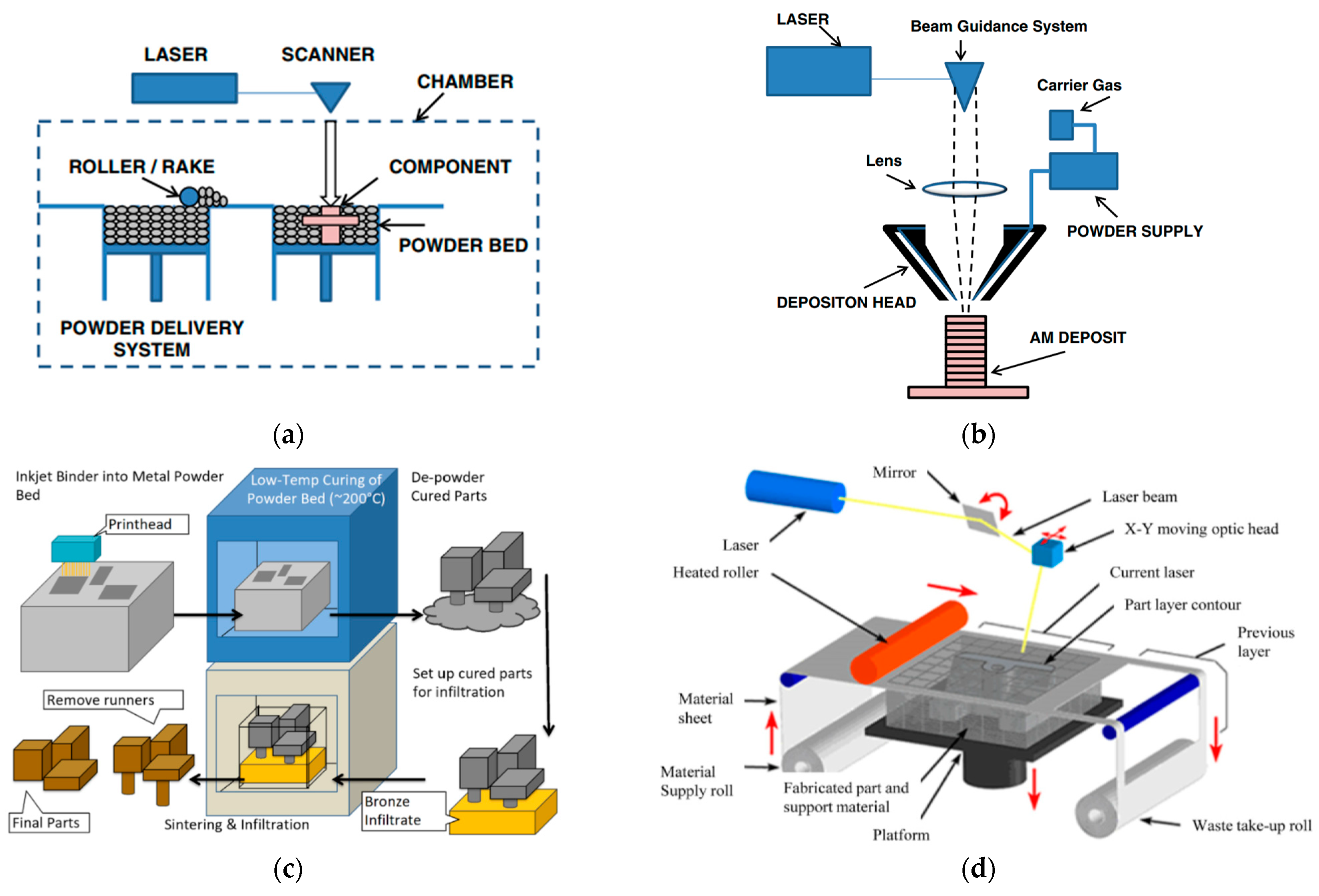
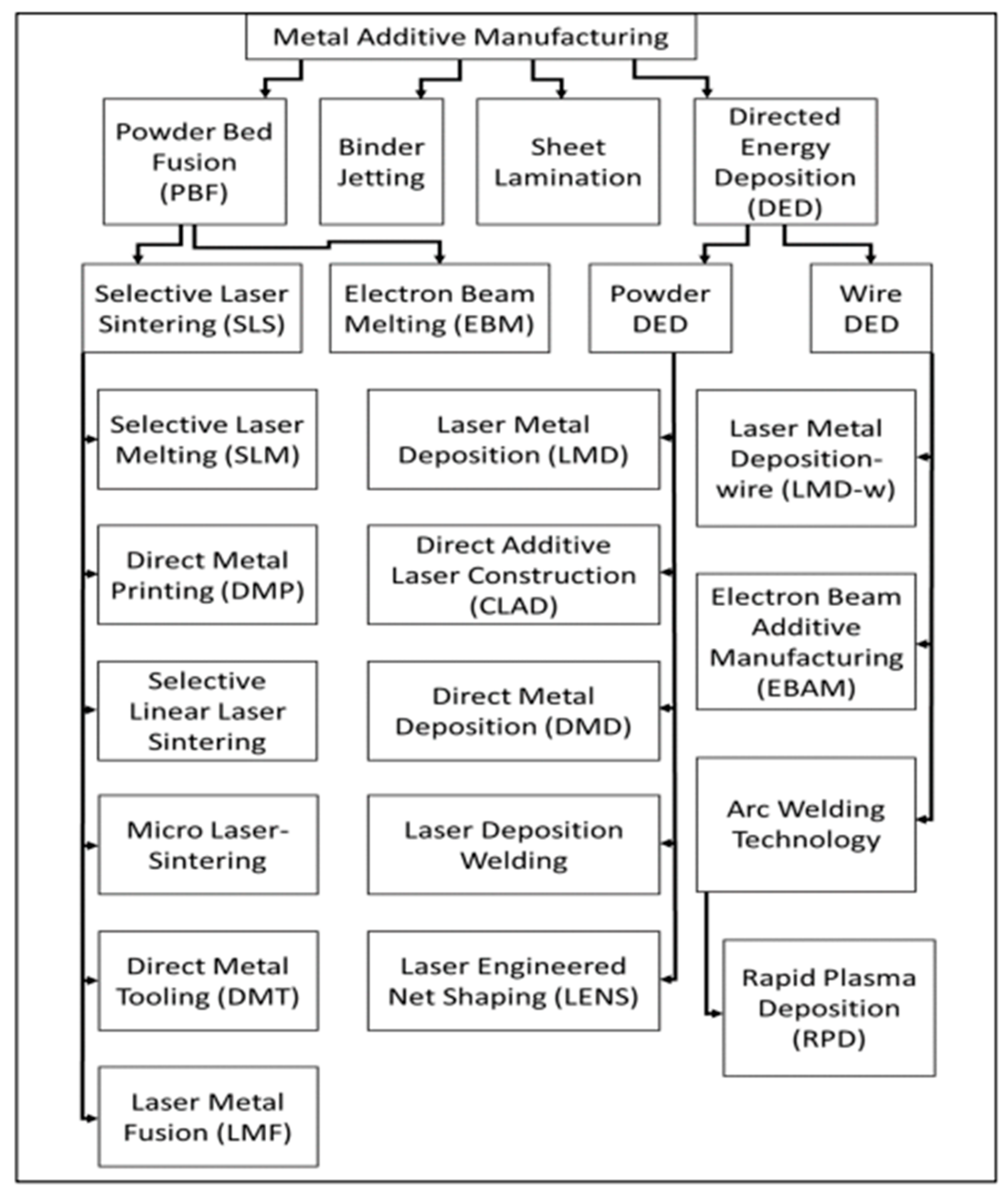
:1. Introduction
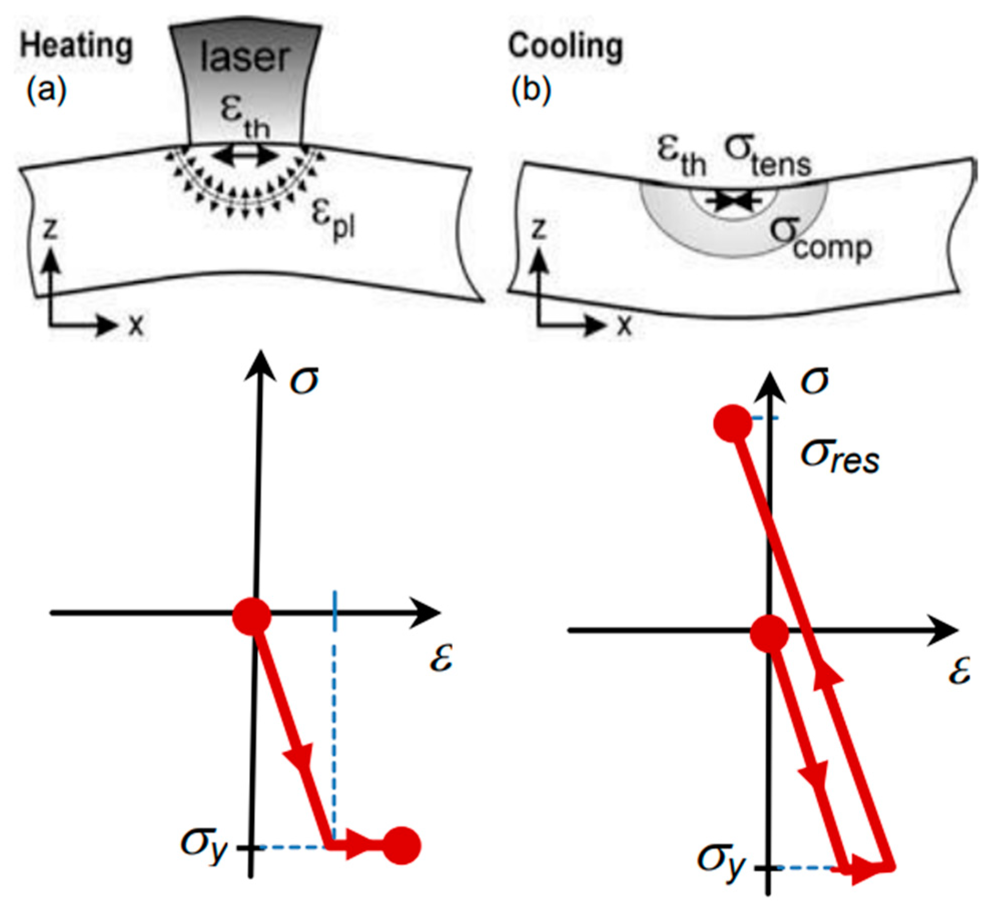
2. Types and Mechanisms of Residual Stress in AM
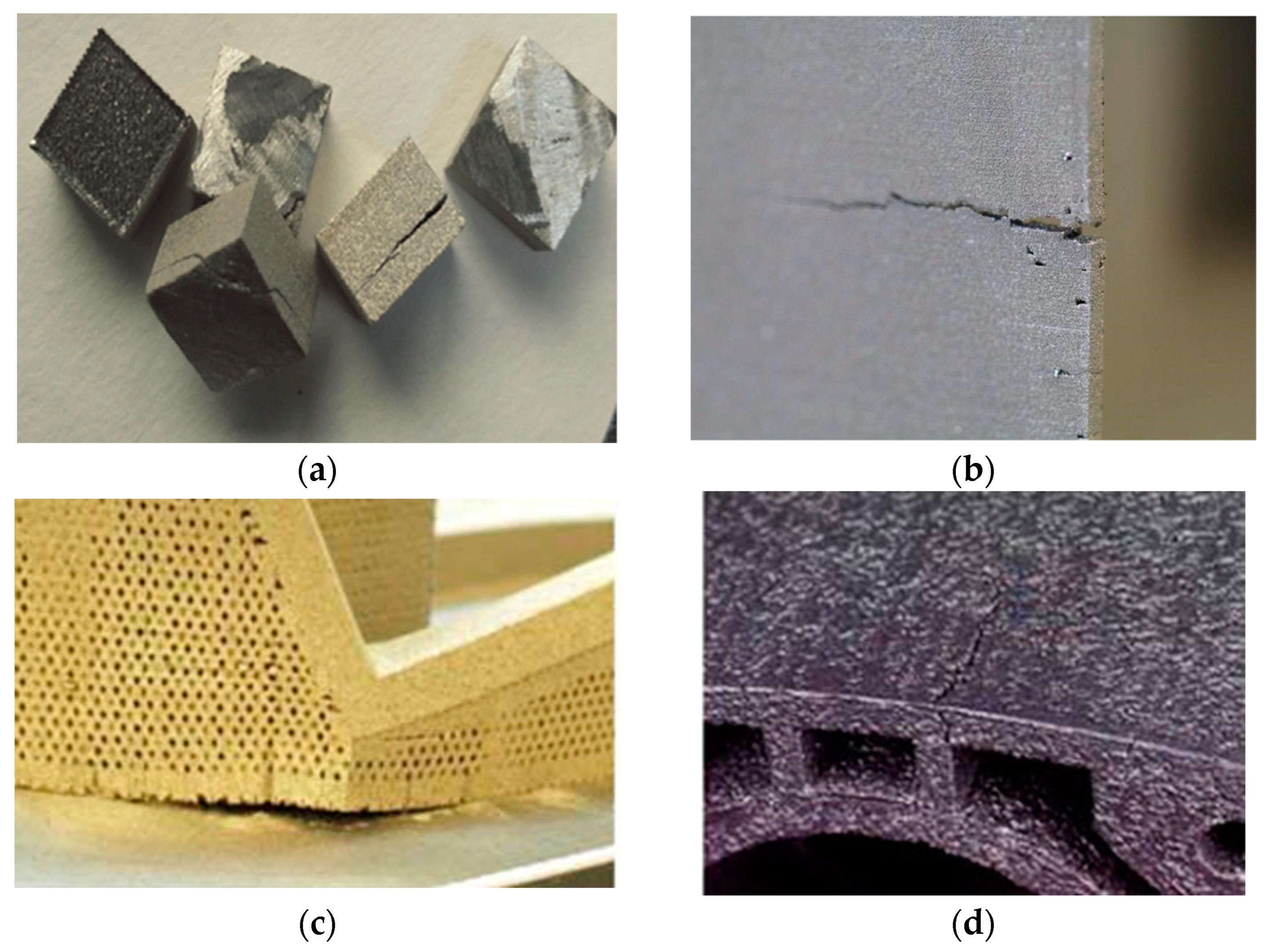
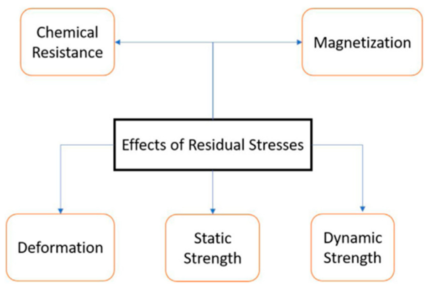
3. Effects of Residual Stress on Part Quality and Mechanical Characteristics
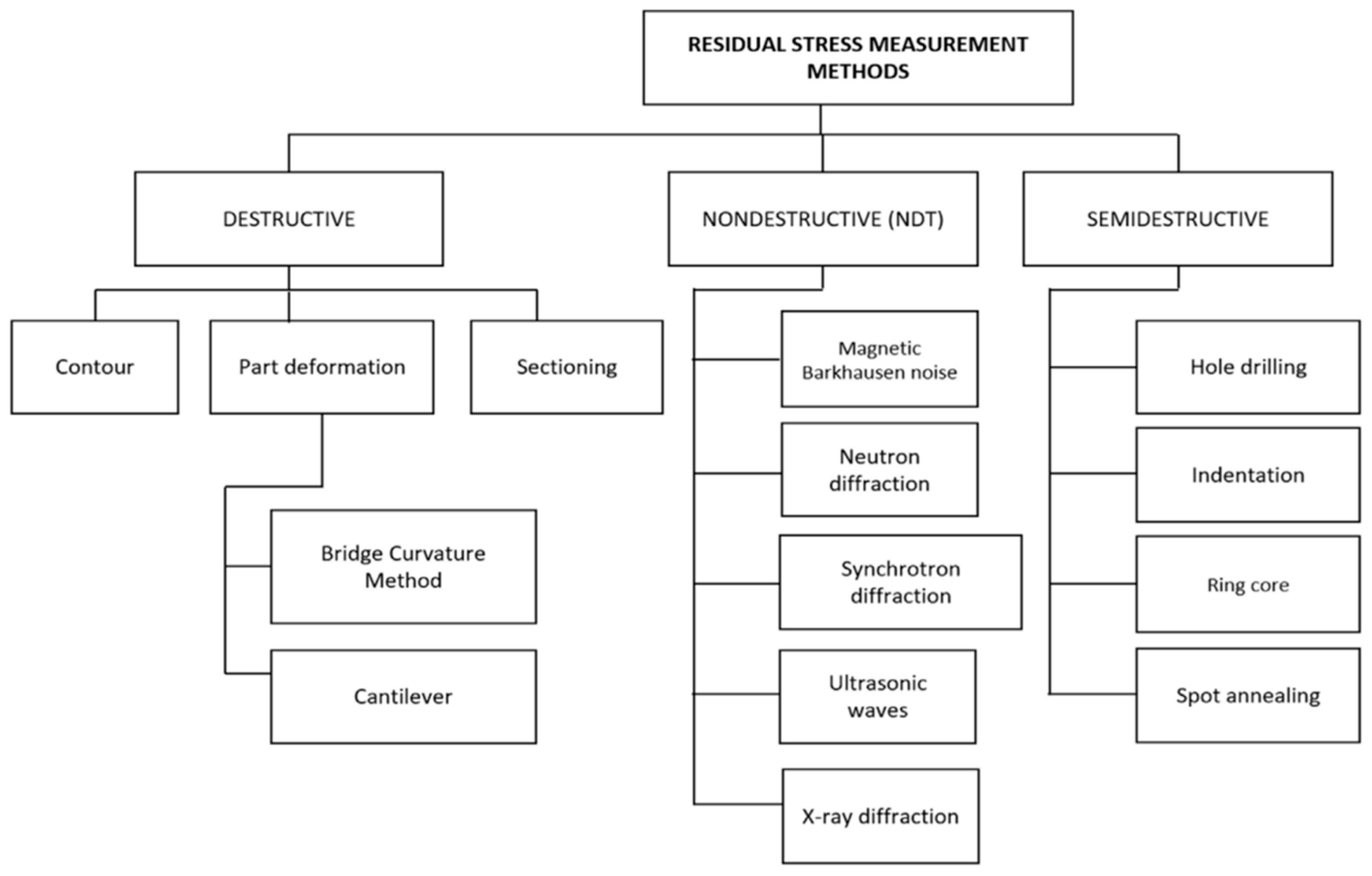
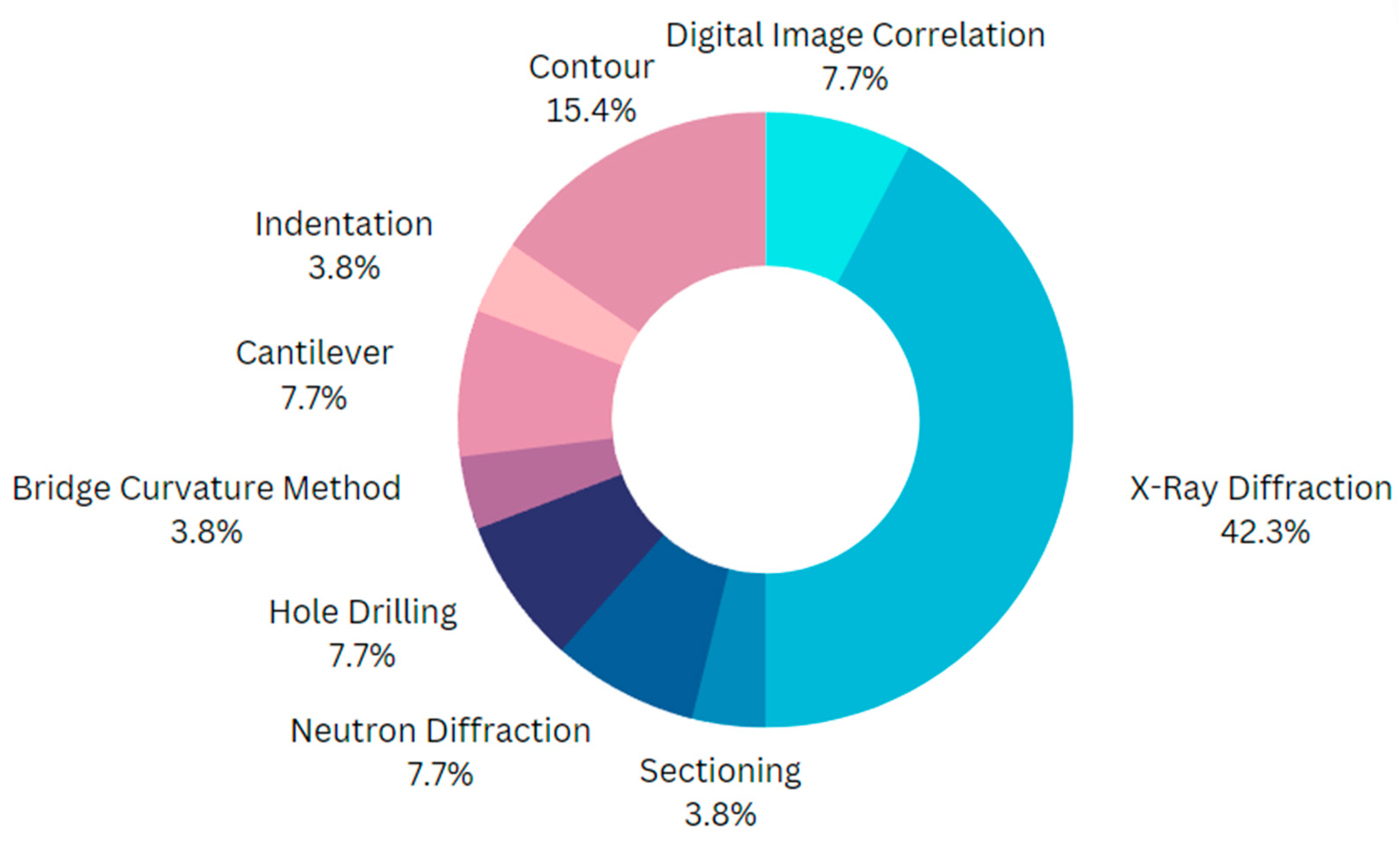
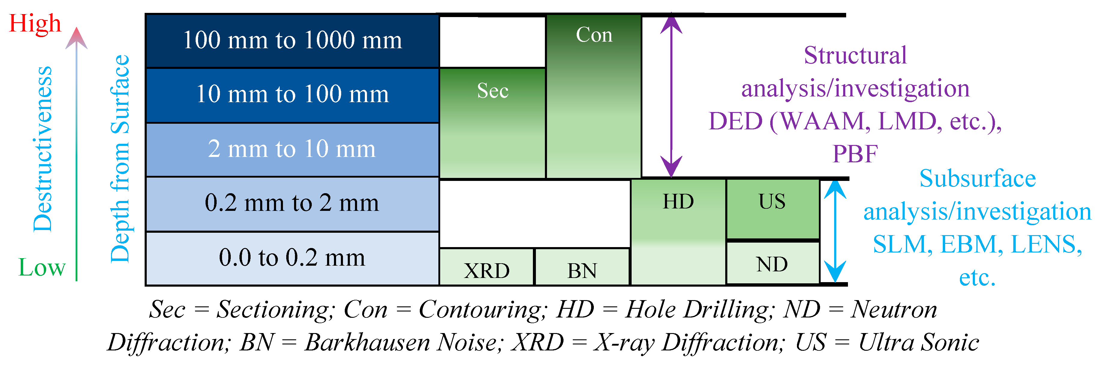
4. Measurement of Residual Stress
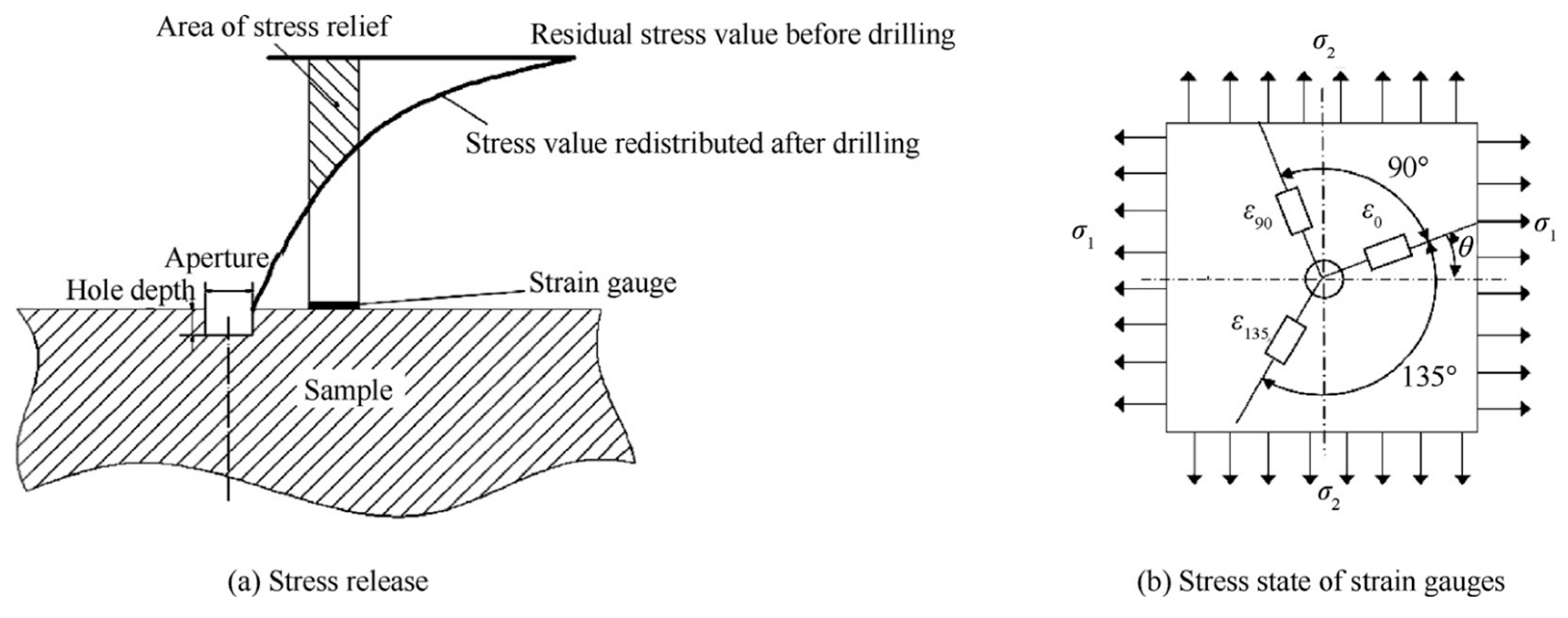
4.1. Destructive and Semi-Destructive Methods
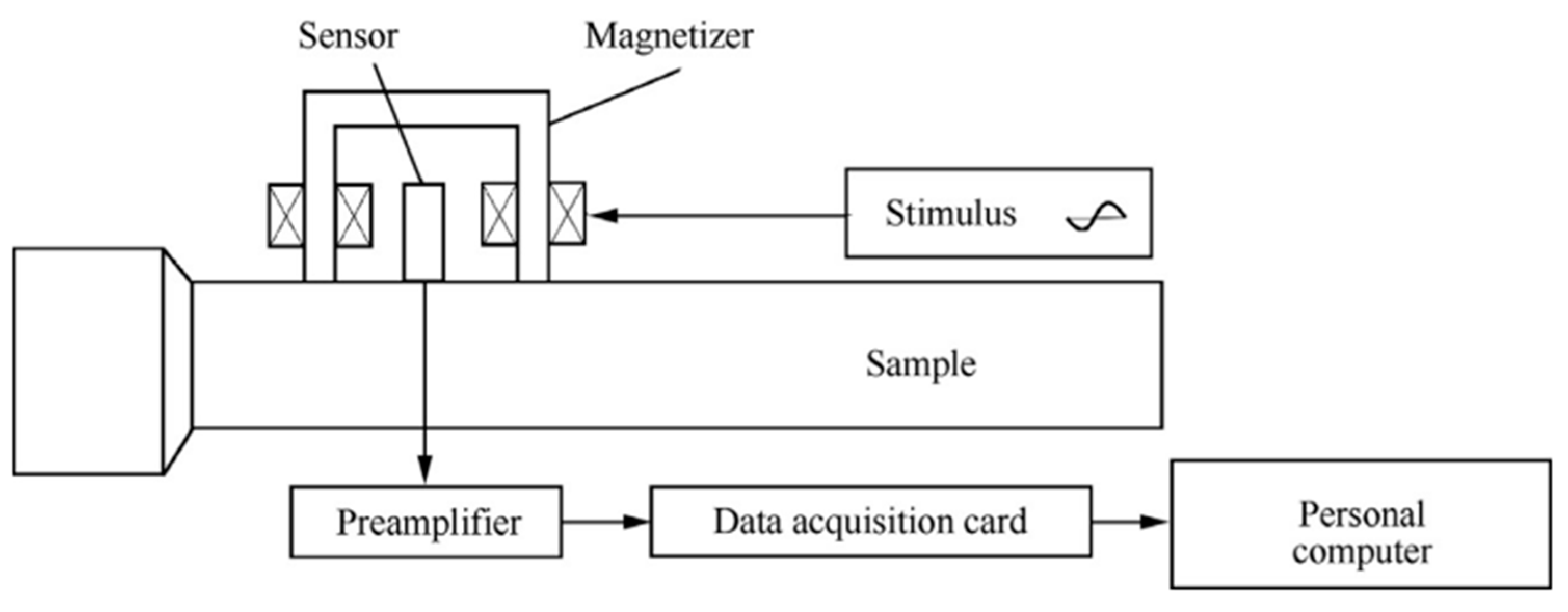
4.2. Non-Destructive Methods
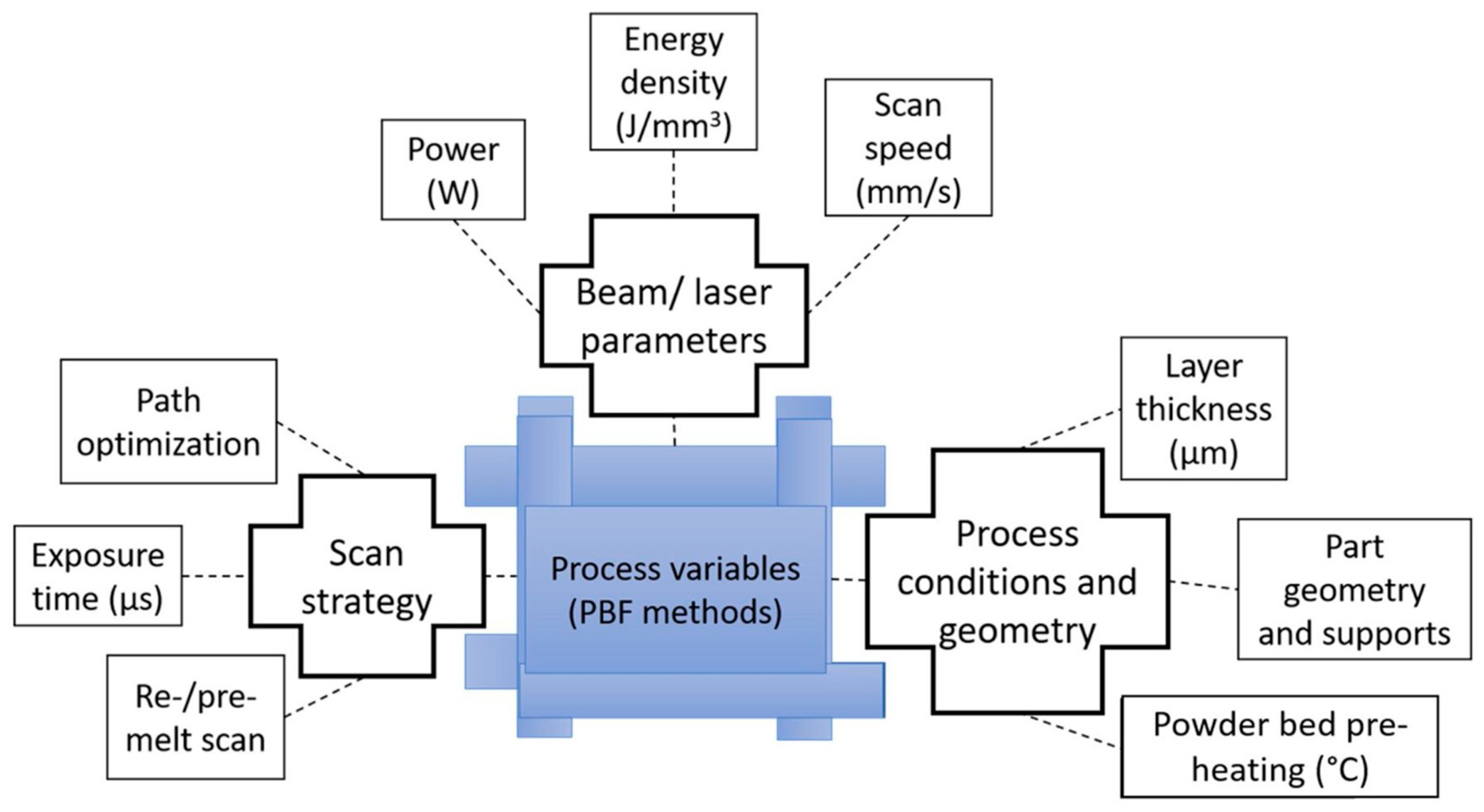
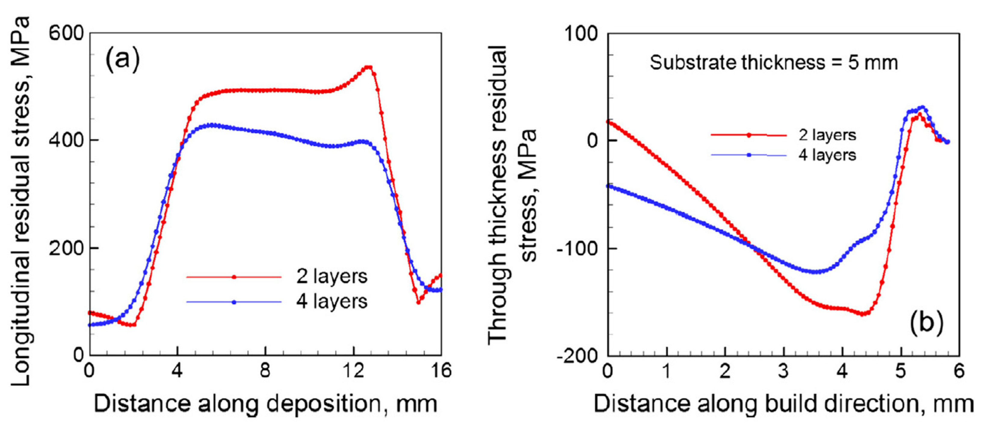
5. Effects of Process Parameters on Residual Stress
6. Numerical Modelling Approach and Validation for Residual Stress
7. Methods for Mitigating Residual Stress
7.1. Heat Treatment
7.2. Laser Shock Peening (LSP)
7.3. Rolling
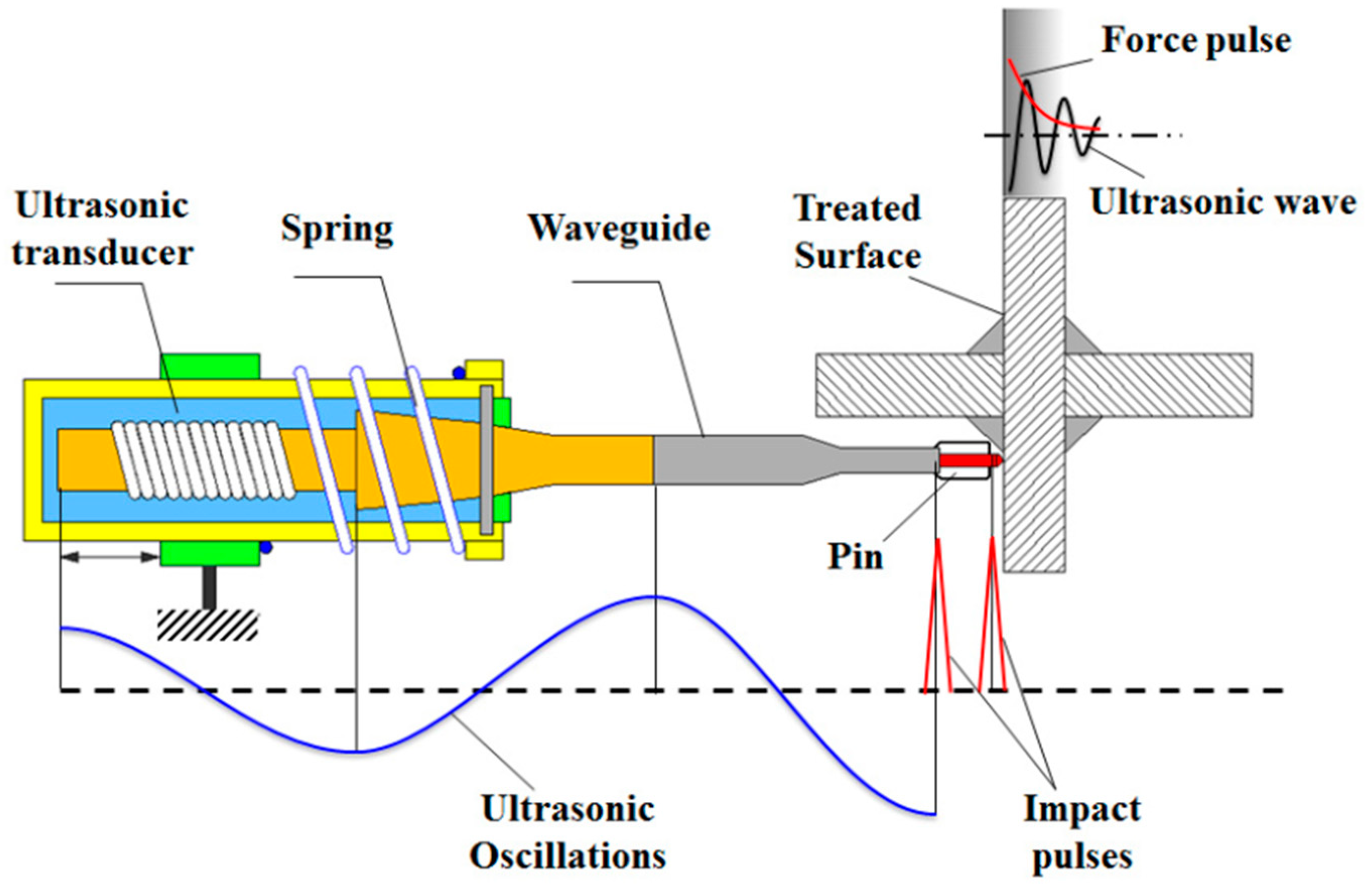
7.4. Ultrasonic Impact Treatment (UIT)
8. Conclusions
9. Recommendations for Future Research on Residual Stress in AM
Author Contributions
Funding
Data Availability Statement
Acknowledgments
Conflicts of Interest
References
- DebRoy, T.; Wei, H.L.; Zuback, J.S.; Mukherjee, T.; Elmer, J.W.; Milewski, J.O.; Beese, A.M.; Wilson-Heid, A.; De, A.; Zhang, W. Additive manufacturing of metallic components—Process, structure and properties. Prog. Mater. Sci. 2018, 92, 112–224. [Google Scholar] [CrossRef]
- Syrlybayev, D.; Seisekulova, A.; Talamona, D.; Perveen, A. The Post-Processing of Additive Manufactured Polymeric and Metallic Parts. J. Manuf. Mater. Process. 2022, 6, 116. [Google Scholar] [CrossRef]
- Gu, D.; Shi, X.; Poprawe, R.; Bourell, D.L.; Setchi, R.; Zhu, J. Material-structure-performance integrated laser-metal additive manufacturing. Science 2021, 372, eabg1487. [Google Scholar] [CrossRef] [PubMed]
- Meng, Z.; He, J.; Li, J.; Su, Y.; Li, D. Melt-based, solvent-free additive manufacturing of biodegradable polymeric scaffolds with designer microstructures for tailored mechanical/biological properties and clinical applications. Virtual Phys. Prototyp. 2020, 15, 417–444. [Google Scholar] [CrossRef]
- Yang, Y.; Lu, C.; Peng, S.; Shen, L.; Wang, D.; Qi, F.; Shuai, C. Laser additive manufacturing of Mg-based composite with improved degradation behavior. Virtual Phys. Prototyp. 2020, 15, 278–293. [Google Scholar] [CrossRef]
- Savolainen, J.; Collan, M. How Additive Manufacturing Technology Changes Business Models?—Review of Literature. Addit. Manuf. 2020, 32, 101070. [Google Scholar] [CrossRef]
- Attaran, M. The rise of 3-D printing: The advantages of additive manufacturing over traditional manufacturing. Bus. Horiz. 2017, 60, 677–688. [Google Scholar] [CrossRef]
- Murr, L.E.; Gaytan, S.M.; Ramirez, D.A.; Martinez, E.; Hernandez, J.; Amato, K.N.; Shindo, P.W.; Medina, F.R.; Wicker, R.B. Metal Fabrication by Additive Manufacturing Using Laser and Electron Beam Melting Technologies. J. Mater. Sci. Technol. 2012, 28, 1–14. [Google Scholar] [CrossRef]
- Frazier, W.E. Metal Additive Manufacturing: A Review. J. Mater. Eng. Perform. 2014, 23, 1917–1928. [Google Scholar] [CrossRef]
- Amato, K.; Hernandez, J.; Murr, L.; Martinez, E.; Gaytan, S.; Shindo, P.; Collins, S. Comparison of microstructure and properties for a Ni-base super alloy (alloy 625) fabricated by electron beam melting. J. Mater. Sci. Res. 2012, 1, 3. [Google Scholar]
- Mostafaei, A.; Elliott, A.M.; Barnes, J.E.; Li, F.; Tan, W.; Cramer, C.L.; Nandwana, P.; Chmielus, M. Binder jet 3D printing—Process parameters, materials, properties, modeling, and challenges. Prog. Mater. Sci. 2020, 119, 100707. [Google Scholar] [CrossRef]
- Ahn, D.; Kweon, J.-H.; Choi, J.; Lee, S. Quantification of surface roughness of parts processed by laminated object manufacturing. J. Mater. Process. Technol. 2012, 212, 339–346. [Google Scholar] [CrossRef]
- Carpenter, K.; Tabei, A. On Residual Stress Development, Prevention, and Compensation in Metal Additive Manufacturing. Materials 2020, 13, 255. [Google Scholar] [CrossRef] [PubMed] [Green Version]
- Taheri, H.; Shoaib, M.R.B.M.; Koester, L.W.; Bigelow, T.A.; Collins, P.C.; Bond, L.J. Powder-based additive manufacturing—A review of types of defects, generation mechanisms, detection, property evaluation and metrology. Int. J. Addit. Subtract. Mater. Manuf. 2017, 1, 172–209. [Google Scholar] [CrossRef] [Green Version]
- Zhang, J.; Toh, A.Y.X.; Wang, H.; Lu, W.F.; Fuh, J.Y.H. Vibration-assisted conformal polishing of additively manufactured structured surface. Proc. Inst. Mech. Eng. Part C J. Mech. Eng. Sci. 2018, 233, 4154–4164. [Google Scholar] [CrossRef]
- Chan, K.S.; Koike, M.; Mason, R.L.; Okabe, T. Fatigue Life of Titanium Alloys Fabricated by Additive Layer Manufacturing Techniques for Dental Implants. Met. Mater. Trans. A 2012, 44, 1010–1022. [Google Scholar] [CrossRef]
- Gisario, A.; Kazarian, M.; Martina, F.; Mehrpouya, M. Metal additive manufacturing in the commercial aviation industry: A review. J. Manuf. Syst. 2019, 53, 124–149. [Google Scholar] [CrossRef]
- Wang, K.; Qiu, M.; Jiao, C.; Gu, J.; Xie, D.; Wang, C.J.; Tang, X.; Wei, Z.; Shen, L. Study on defect-free debinding green body of ceramic formed by DLP technology. Ceram. Int. 2019, 46, 2438–2446. [Google Scholar] [CrossRef]
- Chuang, A.; Erlebacher, J. Challenges and Opportunities for Integrating Dealloying Methods into Additive Manufacturing. Materials 2020, 13, 3706. [Google Scholar] [CrossRef]
- Bartlett, J.L.; Li, X. An overview of residual stresses in metal powder bed fusion. Addit. Manuf. 2019, 27, 131–149. [Google Scholar] [CrossRef]
- Acevedo, R.; Sedlak, P.; Kolman, R.; Fredel, M. Residual stress analysis of additive manufacturing of metallic parts using ultra-sonic waves: State of the art review. J. Mater. Res. Technol. 2020, 9, 9457–9477. [Google Scholar] [CrossRef]
- Karunakaran, R.; Ortgies, S.; Tamayol, A.; Bobaru, F.; Sealy, M.P. Additive manufacturing of magnesium alloys. Bioact. Mater. 2020, 5, 44–54. [Google Scholar] [CrossRef] [PubMed]
- Shiomi, M.; Osakada, K.; Nakamura, K.; Yamashita, T.; Abe, F. Residual Stress within Metallic Model Made by Selective Laser Melting Process. CIRP Ann. 2004, 53, 195–198. [Google Scholar] [CrossRef]
- Mercelis, P.; Kruth, J. Residual stresses in selective laser sintering and selective laser melting. Rapid Prototyp. J. 2006, 12, 254–265. [Google Scholar] [CrossRef]
- Buchbinder, D.; Meiners, W.; Pirch, N.; Wissenbach, K.; Schrage, J. Investigation on reducing distortion by preheating during manufacture of aluminum components using selective laser melting. J. Laser Appl. 2013, 26, 012004. [Google Scholar] [CrossRef]
- Zaeh, M.F.; Branner, G. Investigations on residual stresses and deformations in selective laser melting. Prod. Eng. 2009, 4, 35–45. [Google Scholar] [CrossRef]
- Vilaro, T.; Colin, C.; Bartout, J.D. As-Fabricated and Heat-Treated Microstructures of the Ti-6Al-4V Alloy Processed by Selective Laser Melting. Met. Mater. Trans. A 2011, 42, 3190–3199. [Google Scholar] [CrossRef]
- Withers, P.; Bhadeshia, H. Residual stress. part 1–measurement techniques. Mater. Sci. Technol. 2001, 17, 355–365. [Google Scholar] [CrossRef]
- Li, C.; Liu, Z.; Fang, X.; Guo, Y. Residual Stress in Metal Additive Manufacturing. Procedia CIRP 2018, 71, 348–353. [Google Scholar] [CrossRef]
- Palanivel, S.; Nelaturu, P.; Glass, B.; Mishra, R. Friction stir additive manufacturing for high structural performance through microstructural control in an Mg based WE43 alloy. Mater. Des. 2015, 65, 934–952. [Google Scholar] [CrossRef]
- López, C.; Elías-Zúñiga, A.; Jiménez, I.; Martínez-Romero, O.; Siller, H.R.; Diabb, J.M. Experimental Determination of Residual Stresses Generated by Single Point Incremental Forming of AlSi10Mg Sheets Produced Using SLM Additive Manufacturing Process. Materials 2018, 11, 2542. [Google Scholar] [CrossRef] [PubMed] [Green Version]
- Zhao, X.; Li, S.; Zhang, M.; Liu, Y.; Sercombe, T.B.; Wang, S.; Hao, Y.; Yang, R.; Murr, L.E. Comparison of the microstructures and mechanical properties of Ti–6Al–4V fabricated by selective laser melting and electron beam melting. Mater. Des. 2016, 95, 21–31. [Google Scholar] [CrossRef]
- Li, C.; Guo, Y.; Zhao, J. Interfacial phenomena and characteristics between the deposited material and substrate in selective laser melting Inconel 625. J. Mater. Process. Technol. 2017, 243, 269–281. [Google Scholar] [CrossRef]
- Liu, Z.; Ma, C.; Chang, Z.; Yan, P.; Li, F. Advances in crack formation mechanism and inhibition strategy for ceramic additive manufacturing. J. Eur. Ceram. Soc. 2023, 43, 5078–5098. [Google Scholar] [CrossRef]
- Wagner, L. Mechanical surface treatments on titanium, aluminum and magnesium alloys. Mater. Sci. Eng. A 1999, 263, 210–216. [Google Scholar] [CrossRef]
- Lu, Y.; Wu, S.; Gan, Y.; Huang, T.; Yang, C.; Junjie, L.; Lin, J. Study on the microstructure, mechanical property and residual stress of SLM Inconel-718 alloy manufactured by differing island scanning strategy. Opt. Laser Technol. 2015, 75, 197–206. [Google Scholar] [CrossRef]
- Parry, L.; Ashcroft, I.; Wildman, R. Understanding the effect of laser scan strategy on residual stress in selective laser melting through thermo-mechanical simulation. Addit. Manuf. 2016, 12, 1–15. [Google Scholar] [CrossRef] [Green Version]
- Zäh, M.F.; Lutzmann, S. Modelling and simulation of electron beam melting. Prod. Eng. 2009, 4, 15–23. [Google Scholar] [CrossRef]
- Wang, C.; Jiang, C.; Cai, F.; Zhao, Y.; Zhu, K.; Chai, Z. Effect of shot peening on the residual stresses and microstructure of tungsten cemented carbide. Mater. Des. 2016, 95, 159–164. [Google Scholar] [CrossRef]
- Olabi, A.; Hashmi, M. Stress relief procedures for low carbon steel (1020) welded components. J. Mater. Process. Technol. 1996, 56, 552–562. [Google Scholar] [CrossRef]
- Rangasamy, N.; Rakurty, C.; Balaji, A. A Multiscale Study on Machining Induced Surface Integrity in Ti-6Al-4V Alloy. Procedia CIRP 2022, 108, 787–792. [Google Scholar] [CrossRef]
- Rangasamy, N.; Rakurty, C.S.; Maurer, Z. Minimum quantity cutting fluid application for grinding weld flash: Surface integrity evaluation. ASME OPEN J. Eng. 2022, 1, 014503. [Google Scholar] [CrossRef]
- Rakurty, C.S. Targeted and Variable Minimum Quantity Cutting Fluid Application for Finish Machining of Steels. Ph.D. Dissertation, The University of Utah, Salt Lake City, UT, USA, 2019. [Google Scholar]
- Rakurty, C.; Rangasamy, N.; Balaji, A.; Pandey, S. A Finite Element Analysis Based Approach to Understand the Effects of Targeted Minimum Quantity Cutting Fluid Application on Surface Integrity. Procedia CIRP 2022, 108, 613–618. [Google Scholar] [CrossRef]
- Guo, J.; Fu, H.; Pan, B.; Kang, R. Recent progress of residual stress measurement methods: A review. Chin. J. Aeronaut. 2021, 34, 54–78. [Google Scholar] [CrossRef]
- Huang, X.; Liu, Z.; Xie, H. Recent progress in residual stress measurement techniques. Acta Mech. Solida Sin. 2013, 26, 570–583. [Google Scholar] [CrossRef] [Green Version]
- Kandil, F.A.; Lord, J.D. A Review of Residual Stress Measurement Methods, a Guide to Technique Selection; NPL Report MAT(A)04; National Physical Laboratory: Teddington, UK, 2001. [Google Scholar]
- Mazzolani, F.M. Aluminium Alloy Structures, 2nd ed.; CRC Press: Boca Raton, FL, USA, 1995; ISBN 978-0419177708. [Google Scholar]
- Young, B.; Lui, W.-M. Behavior of Cold-Formed High Strength Stainless Steel Sections. J. Struct. Eng. 2005, 131, 1738–1745. [Google Scholar] [CrossRef]
- Prime, M.B.; Hughes, D.J.; Webster, P.J. Weld Application of a New Method for Cross-Sectional Residual Stress Mapping. In Proceedings of the 2001 SEM Annual Conference on Experimental and Applied Mechanics, Portland, OR, USA, 4–6 June 2001; pp. 608–611. [Google Scholar]
- Prime, M.B.; Martineau, R.L. Mapping Residual Stresses after Foreign Object Damage Using the Contour Method. Mater. Sci. Forum 2002, 404–407, 521–526. [Google Scholar] [CrossRef] [Green Version]
- Smith, D.J.; Bouchard, P.J.; George, D. Measurement and prediction of through thickness residual stresses in thick section welds. J. Strain Anal. 2000, 35, 287–305. [Google Scholar] [CrossRef]
- Norton, J.H.; Rosenthal, D. Stress measurement by X-ray diffraction. Proc. Soc. Exp. Stress Anal. 1944, 1, 73–76. [Google Scholar]
- Norton, J.H.; Rosenthal, D. Application of the X-ray method of stress measurement to problems involving residual stress in metals. Proc. Soc. Exp. Stress Anal. 1944, 1, 81–90. [Google Scholar]
- Kim, S.-H.; Kim, J.-B.; Lee, W.-J. Numerical prediction and neutron diffraction measurement of the residual stresses for a modified 9Cr–1Mo steel weld. J. Mater. Process. Technol. 2009, 209, 3905–3913. [Google Scholar] [CrossRef]
- Clapham, L.; Abdullah, K.; Jeswiet, J.; Wild, P.; Rogge, R. Neutron diffraction residual stress mapping in same gauge and differential gauge tailor-welded blanks. J. Mater. Process. Technol. 2004, 148, 177–185. [Google Scholar] [CrossRef]
- Altpeter, I.; Dobmann, G.; Kröning, M.; Rabung, M.; Szielasko, S. Micro-magnetic evaluation of micro residual stresses of the IInd and IIIrd order. NDT E Int. 2009, 42, 283–290. [Google Scholar] [CrossRef]
- Yelbay, H.I.; Cam, I.; Gür, C.H. Non-destructive determination of residual stress state in steel weldments by Magnetic Barkhausen Noise technique. NDT E Int. 2010, 43, 29–33. [Google Scholar] [CrossRef]
- Balahcene, F.; Lu, J. Study of residual stress induced in welded steel by surface longitudinal ultrasonic method. In Proceedings of the SEM Annual Conference on Theoretical, Experimental and Computational Mechanics, Cincinnati, OH, USA, 7–9 June 1999; pp. 331–334. [Google Scholar]
- Leon-Salamanca, T.; Bray, D.E. Residual stress measurement in steel plates and welds using critically refracted waves. Res. Nondestruct. Eval. 1996, 7, 169–184. [Google Scholar] [CrossRef]
- Mukherjee, T.; Zhang, W.; DebRoy, T. An improved prediction of residual stresses and distortion in additive manufacturing. Comput. Mater. Sci. 2017, 126, 360–372. [Google Scholar] [CrossRef] [Green Version]
- Mukherjee, T.; Zuback, J.S.; De, A.; DebRoy, T. Printability of alloys for additive manufacturing. Sci. Rep. 2016, 6, 19717. [Google Scholar] [CrossRef] [Green Version]
- Vastola, G.; Zhang, G.; Pei, Q.; Zhang, Y.-W. Controlling of residual stress in additive manufacturing of Ti6Al4V by finite element modeling. Addit. Manuf. 2016, 12, 231–239. [Google Scholar] [CrossRef]
- Zhan, Y.; Liu, C.; Zhang, J.; Mo, G.; Liu, C. Measurement of residual stress in laser additive man-ufacturing TC4 titanium alloy with the laser ultrasonic technique. Mater. Sci. Eng. A 2019, 762, 138093. [Google Scholar] [CrossRef]
- Robinson, J.; Ashton, I.; Fox, P.; Jones, E.; Sutcliffe, C. Determination of the effect of scan strategy on residual stress in laser powder bed fusion additive manufacturing. Addit. Manuf. 2018, 23, 13–24. [Google Scholar] [CrossRef]
- Yadroitsava, I.; Grewar, S.; Hattingh, D.; Yadroitsev, I. Residual Stress in SLM Ti6Al4V Alloy Specimens. Mater. Sci. Forum 2015, 828–829, 305–310. [Google Scholar] [CrossRef]
- Wu, A.S.; Brown, D.W.; Kumar, M.; Gallegos, G.F.; King, W.E. An Experimental Investigation into Additive Manufacturing-Induced Residual Stresses in 316L Stainless Steel. Met. Mater. Trans. A 2014, 45, 6260–6270. [Google Scholar] [CrossRef]
- Kruth, J.P.; Deckers, J.; Yasa, E.; Wauthle, R. Assessing and comparing influencing factors of residual stresses in selective laser melting using a novel analysis method. Proc. Inst. Mech. Eng. B 2012, 226, 980–991. [Google Scholar] [CrossRef]
- Derekar, K.S.; Ahmad, B.; Zhang, X.; Joshi, S.S.; Lawrence, J.; Xu, L.; Melton, G.; Addison, A. Effects of Process Variants on Residual Stresses in Wire Arc Additive Manufacturing of Aluminum Alloy 5183. J. Manuf. Sci. Eng. 2021, 144, 071005. [Google Scholar] [CrossRef]
- Levkulich, N.; Semiatin, S.; Gockel, J.; Middendorf, J.; DeWald, A.; Klingbeil, N. The effect of process parameters on residual stress evolution and distortion in the laser powder bed fusion of Ti-6Al-4V. Addit. Manuf. 2019, 28, 475–484. [Google Scholar] [CrossRef]
- Xiao, Z.; Chen, C.; Zhu, H.; Hu, Z.; Nagarajan, B.; Guo, L.; Zeng, X. Study of residual stress in selective laser melting of Ti6Al4V. Mater. Des. 2020, 193, 108846. [Google Scholar] [CrossRef]
- Ali, H.; Ghadbeigi, H.; Mumtaz, K. Residual stress development in selective laser-melted Ti6Al4V: A parametric thermal modelling approach. Int. J. Adv. Manuf. Technol. 2018, 97, 2621–2633. [Google Scholar] [CrossRef] [Green Version]
- Zohdi, T.I. Modeling and simulation of cooling-induced residual stresses in heated particulate mixture depositions in additive manufacturing. Comput. Mech. 2015, 56, 613–630. [Google Scholar] [CrossRef]
- Ganeriwala, R.; Zohdi, T.I. Multiphysics Modeling and Simulation of Selective Laser Sintering Manufacturing Processes. Procedia CIRP 2014, 14, 299–304. [Google Scholar] [CrossRef] [Green Version]
- Song, X.; Feih, S.; Zhai, W.; Sun, C.-N.; Li, F.; Maiti, R.; Wei, J.; Yang, Y.; Oancea, V.; Brandt, L.R.; et al. Advances in additive manufacturing process simulation: Residual stresses and distortion predictions in complex metallic components. Mater. Des. 2020, 193, 108779. [Google Scholar] [CrossRef]
- Ning, J.; Praniewicz, M.; Wang, W.; Dobbs, J.R.; Liang, S.Y. Analytical modeling of part distortion in metal additive manufacturing. Int. J. Adv. Manuf. Technol. 2020, 107, 49–57. [Google Scholar] [CrossRef]
- Mirkoohi, E.; Li, D.; Garmestani, H.; Liang, S.Y. Residual stress modeling considering microstructure evolution in metal additive manufacturing. J. Manuf. Process. 2021, 68, 383–397. [Google Scholar] [CrossRef]
- Zhao, X.; Iyer, A.; Promoppatum, P.; Yao, S.-C. Numerical modeling of the thermal behavior and residual stress in the direct metal laser sintering process of titanium alloy products. Addit. Manuf. 2017, 14, 126–136. [Google Scholar] [CrossRef]
- Panda, B.K.; Sahoo, S. Numerical simulation of residual stress in laser based additive manufacturing process. IOP Conf. Ser. Mater. Sci. Eng. 2018, 338, 012030. [Google Scholar] [CrossRef] [Green Version]
- Liu, H.; Sparks, T.; Liou, F.; Dietrich, D.M. Residual Stress and Deformation Modelling for Metal Additive Manufacturing Processes. In Proceedings of the World Congress on Mechanical, Chemical, and Material Engineering, Barcelona, Spain, 20–21 July 2015. [Google Scholar]
- Li, P.; Gong, Y.; Liang, C.; Yang, Y.; Cai, M. Effect of post-heat treatment on residual stress and tensile strength of hybrid additive and subtractive manufacturing. Int. J. Adv. Manuf. Technol. 2019, 103, 2579–2592. [Google Scholar] [CrossRef]
- Kim, I.; Park, S.C.; Kim, Y.I.; Kim, D.-K.; Lee, K.-A.; Oh, S.J.; Lee, B. Surface residual stress analysis of additive manufactured AlSi10Mg alloys. J. Alloys Compd. 2023, 945, 169315. [Google Scholar] [CrossRef]
- Wang, X.; Chou, K. The effects of stress relieving heat treatment on the microstructure and residual stress of Inconel 718 fabricated by laser metal powder bed fusion additive manufacturing process. J. Manuf. Process. 2019, 48, 154–163. [Google Scholar] [CrossRef]
- Williams, R.J.; Vecchiato, F.; Kelleher, J.; Wenman, M.R.; Hooper, P.A.; Davies, C.M. Effects of heat treatment on residual stresses in the laser powder bed fusion of 316L stainless steel: Finite element predictions and neutron diffraction measurements. J. Manuf. Process. 2020, 57, 641–653. [Google Scholar] [CrossRef]
- Kalentics, N.; Boillat, E.; Peyre, P.; Ćirić-Kostić, S.; Bogojević, N.; Logé, R.E. Tailoring residual stress profile of Selective Laser Melted parts by Laser Shock Peening. Addit. Manuf. 2017, 16, 90–97. [Google Scholar] [CrossRef] [Green Version]
- Kalentics, N.; de Seijas, M.O.V.; Griffiths, S.; Leinenbach, C.; Logé, R.E. 3D laser shock peening—A new method for improving fatigue properties of selective laser melted parts. Addit. Manuf. 2020, 33, 101112. [Google Scholar] [CrossRef]
- Sandmann, P.; Keller, S.; Kashaev, N.; Ghouse, S.; Hooper, P.A.; Klusemann, B.; Davies, C.M. Influence of laser shock peening on the residual stresses in additively manufactured 316L by Laser Powder Bed Fusion: A combined experimental–numerical study. Addit. Manuf. 2022, 60, 103204. [Google Scholar] [CrossRef]
- Over, V.; Donovan, J.; Yao, Y.L. The Effect of Laser Shock Peening on Back Stress of Additively Manufactured Stainless Steel Parts. J. Manuf. Sci. Eng. 2023, 145, 041005. [Google Scholar] [CrossRef]
- Madireddy, G.; Li, C.; Liu, J.; Sealy, M.P. Modeling thermal and mechanical cancellation of residual stress from hybrid additive manufacturing by laser peening. Nanotechnol. Precis. Eng. 2019, 2, 49–60. [Google Scholar] [CrossRef]
- Sun, R.; Li, L.; Zhu, Y.; Guo, W.; Peng, P.; Cong, B.; Sun, J.; Che, Z.; Li, B.; Guo, C.; et al. Microstructure, residual stress and tensile properties control of wire-arc additive manufactured 2319 aluminum alloy with laser shock peening. J. Alloys Compd. 2018, 747, 255–265. [Google Scholar] [CrossRef]
- Xia, C.; Pan, Z.; Polden, J.; Li, H.; Xu, Y.; Chen, S.; Zhang, Y. A review on wire arc additive manufacturing: Monitoring, control and a framework of automated system. J. Manuf. Syst. 2020, 57, 31–45. [Google Scholar] [CrossRef]
- Martina, F.; Roy, M.J.; Szost, B.A.; Terzi, S.; Colegrove, P.A.; Williams, S.W.; Withers, P.J.; Meyer, J.; Hofmann, M. Residual stress of as-deposited and rolled wire+arc additive manufacturing Ti–6Al–4V components. Mater. Sci. Technol. 2016, 32, 1439–1448. [Google Scholar] [CrossRef] [Green Version]
- Hönnige, J.; Colegrove, P.; Ahmad, B.; Fitzpatrick, M.; Ganguly, S.; Lee, T.; Williams, S. Residual stress and texture control in Ti-6Al-4V wire + arc additively manufactured intersections by stress relief and rolling. Mater. Des. 2018, 150, 193–205. [Google Scholar] [CrossRef] [Green Version]
- Cozzolino, L.D.; Coules, H.E.; Colegrove, P.A.; Wen, S. Investigation of post-weld rolling methods to reduce residual stress and distortion. J. Mater. Process. Technol. 2017, 247, 243–256. [Google Scholar] [CrossRef]
- Colegrove, P.A.; Coules, H.E.; Fairman, J.; Martina, F.; Kashoob, T.; Mamash, H.; Cozzolino, L.D. Microstructure and residual stress improvement in wire and arc additively manufactured parts through high-pressure rolling. J. Mater. Process. Technol. 2013, 213, 1782–1791. [Google Scholar] [CrossRef]
- Yuan, K.; Sumi, Y. Modelling of ultrasonic impact treatment (UIT) of welded joints and its effect on fatigue strength. Frat. Ed Integrità Strutt. 2015, 9. [Google Scholar] [CrossRef]
- Everton, S.K.; Hirsch, M.; Stravroulakis, P.; Leach, R.K.; Clare, A.T. Review of in-situ process monitoring and in-situ metrology for metal additive manufacturing. Mater. Des. 2016, 95, 431–445. [Google Scholar] [CrossRef]
- Chen, J.; Chu, J.; Jiang, W.; Yao, B.; Zhou, F.; Wang, Z.; Zhao, P. Experimental and Numerical Simulation to Study the Reduction of Welding Residual Stress by Ultrasonic Impact Treatment. Materials 2020, 13, 837. [Google Scholar] [CrossRef] [Green Version]
- Tang, L.; Ince, A.; Zheng, J. Numerical modeling of residual stresses and fatigue damage assessment of ultrasonic impact treated 304L stainless steel welded joints. Eng. Fail. Anal. 2019, 108, 104277. [Google Scholar] [CrossRef]
- Cococcetta, N.M.; Pearl, D.; Jahan, M.P.; Ma, J. Investigating surface finish, burr formation, and tool wear during machining of 3D printed carbon fiber reinforced polymer composite. J. Manuf. Process. 2020, 56, 1304–1316. [Google Scholar] [CrossRef]
- Cococcetta, N.; Jahan, M.P.; Schoop, J.; Ma, J.; Pearl, D.; Hassan, M. Post-processing of 3D printed thermoplastic CFRP composites using cryogenic machining. J. Manuf. Process. 2021, 68, 332–346. [Google Scholar] [CrossRef]
- Chaturvedi, M.; Scutelnicu, E.; Rusu, C.C.; Mistodie, L.R.; Mihailescu, D.; Arungalai Vendan, S. Wire arc additive manufacturing: Review on recent findings and challenges in industrial applications and materials characterization. Metals 2021, 11, 939. [Google Scholar] [CrossRef]
- Richter, A.; Gehling, T.; Treutler, K.; Wesling, V.; Rembe, C. Real-time measurement of temperature and volume of the weld pool in wire-arc additive manufacturing. Meas. Sens. 2021, 17, 100060. [Google Scholar] [CrossRef]
- Hrabe, N.; Gnäupel-Herold, T.; Quinn, T. Fatigue properties of a titanium alloy (Ti–6Al–4V) fabricated via electron beam melting (EBM): Effects of internal defects and residual stress. Int. J. Fatigue 2017, 94, 202–210. [Google Scholar] [CrossRef] [Green Version]
- Tillmann, W.; Schaak, C.; Nellesen, J.; Schaper, M.; Aydinöz, M.; Hoyer, K.-P. Hot isostatic pressing of IN718 components manufactured by selective laser melting. Addit. Manuf. 2017, 13, 93–102. [Google Scholar] [CrossRef]
- Günther, J.; Krewerth, D.; Lippmann, T.; Leuders, S.; Tröster, T.; Weidner, A.; Biermann, H.; Niendorf, T. Fatigue life of additively manufactured Ti–6Al–4V in the very high cycle fatigue regime. Int. J. Fatigue 2017, 94, 236–245. [Google Scholar] [CrossRef]
- Ye, C.; Telang, A.; Gill, A.S.; Suslov, S.; Idell, Y.; Zweiacker, K.; Wiezorek, J.M.K.; Zhou, Z.; Qian, D.; Mannava, S.R.; et al. Gradient nanostructure and residual stresses induced by Ultrasonic Nano-crystal Surface Modification in 304 austenitic stainless steel for high strength and high ductility. Mater. Sci. Eng. A 2014, 613, 274–288. [Google Scholar] [CrossRef] [Green Version]
- Kattoura, M.; Telang, A.; Mannava, S.R.; Qian, D.; Vasudevan, V.K. Effect of Ultrasonic Nanocrystal Surface Modification on Residual Stress, Microstructure and Fatigue Behavior of ATI 718Plus Alloy. Mater. Sci. Eng. A 2018, 711, 364–377. [Google Scholar] [CrossRef]
- Kahlin, M.; Ansell, H.; Basu, D.; Kerwin, A.; Newton, L.; Smith, B.; Moverare, J. Improved fatigue strength of additively manufactured Ti6Al4V by surface post processing. Int. J. Fatigue 2020, 134, 105497. [Google Scholar] [CrossRef]
- Uzan, N.E.; Ramati, S.; Shneck, R.; Frage, N.; Yeheskel, O. On the Effect of Shot-Peening on Fatigue Resistance of AlSi10Mg Specimens Fabricated by Additive Manufacturing Using Selective Laser Melting (AM-SLM). Addit. Manuf. 2018, 21, 458–464. [Google Scholar] [CrossRef]
- Khatri, A.; Jahan, M.P.; Ma, J. Assessment of tool wear and microstructural alteration of the cutting tools in conventional and sustainable slot milling of Ti-6Al-4V alloy. Int. J. Adv. Manuf. Technol. 2019, 105, 2799–2814. [Google Scholar] [CrossRef]
- Adeniji, D.; Schoop, J.; Gunawardena, S.; Hanson, C.; Jahan, M. Characterization and Modeling of Surface Roughness and Burr Formation in Slot Milling of Polycarbonate. J. Manuf. Mater. Process. 2020, 4, 59. [Google Scholar] [CrossRef]
- Hassan, M.; Ma, J.; Jahan, M.P. Numerical modeling and simulation of machining of 3D printed CFRP composite. Manuf. Lett. 2022, 33, 415–427. [Google Scholar] [CrossRef]
- Boban, J.; Ahmed, A. Finishing the surface micro-layer of additively manufactured TiAl alloy using electro-thermal discharge assisted post-processing. J. Micromanuf. 2023. [Google Scholar] [CrossRef]
- Jahan, M.P.; Wong, Y.S.; Rahman, M. A comparative study of transistor and RC pulse generators for micro-EDM of tungsten carbide. Int. J. Precis. Eng. Manuf. 2008, 9, 3–10. [Google Scholar]
- Rahman, M.A.; Saleh, T.; Jahan, M.P.; McGarry, C.; Chaudhari, A.; Huang, R.; Tauhiduzzaman, M.; Ahmed, A.; Al Mahmud, A.; Bhuiyan, S.; et al. Review of Intelligence for Additive and Subtractive Manufacturing: Current Status and Future Prospects. Micromachines 2023, 14, 508. [Google Scholar] [CrossRef]


| Measurement Technique | Penetration Depth | Spatial Resolution | Applications | Advantages | Disadvantages | References |
|---|---|---|---|---|---|---|
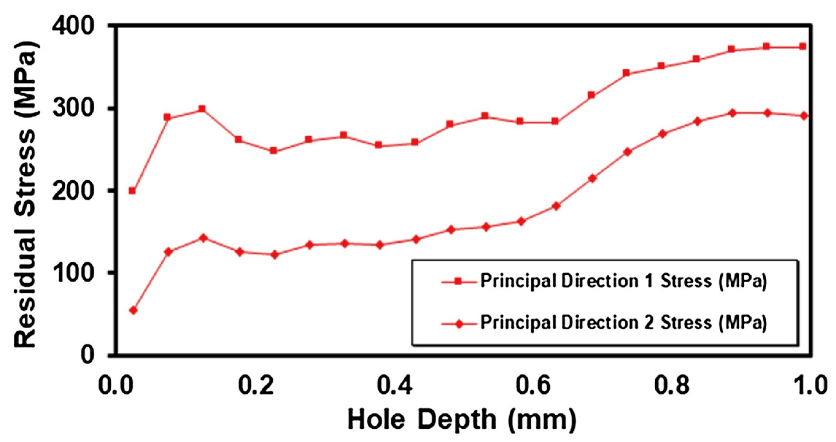
| Hole-drilling | 1.8 mm to 2.0 mm deep | - | Wide range of elastic and isotropic materials, used in machining surface integrity research | Simple experimental setup, straightforward operation, improved accuracy, relatively accurate | Semi-destructive, limited to strain sensitivity, material needs to be machinable, source of errors includes non-cylindrical hole, stress addition due to machining, and eccentricity | [40,43,47] |
| Sectioning | 2 mm to 100 mm | - | Wide range of materials like Structural carbon steel, aluminum, stainless steel etc. | Fast and economical | Destructive, limited stain resolution | [48,49] |
| Contour method | 2 mm to 1000 mm | - | Application includes quenched and impacted thick plates, cold-expanded holes, aluminum alloys, carbon steels | High spatial resolution, wide range of materials, large samples | Destructive, Additional stresses can be introduced, and data interpretation is required | [50,51,52] |
| X-ray diffraction | 100 μm (Ti) 50 μm (Al) | Transverse: 1 mm Depth: 20 μm | Applicable to materials that are crystalline, fine grained, and produce diffraction at any orientation, used in machining surface integrity research | Non-destructive, high accuracy, can measure both macro and micro-RS | Only applicable for measuring RS near the surface, lab-based system, expensive | [53,54] |
| Neutron diffraction | 0.2 mm–100 mm (Al) 0.2 mm–25 mm (steel) 0.2 mm–17 mm (Ti) | Transverse: 20 μm | Wide range of composites and heterogeneous materials | Can measure both macro and micro-RS, non-destructive, optimal penetration and resolution | Lab-based system, expensive, slow detection speed | [55,56] |
| Barkhausen noise method | Depends on the permeability of the material, Up to 0.2 mm | - | Application is limited to ferromagnetic materials | Non-destructive, can reveal microstructural parameters and surface RS, fast | Only applicable to ferromagnetic materials, low resolution | [57,58] |
| Ultrasonic method | 0.2–2 mm | 0.1–30 m2 | Application includes the determination of RS and applied stress in real structures | Non-destructive, readily available, fast and cost efficient | Limited resolution, accuracy is compromised by the material and external factors | [59,60] |
| Process Variable | Effects due to Variation | Remarks | References |
|---|---|---|---|
| Layer thickness | Parts with a thin layer thickness have lower residual stress compared to parts with a thick layer thickness. | Increasing the number of layers from 2 layers to 4 layers for the same height of parts resulted in a 20–30% reduction in RS [61]. | [61,62] |
| Substrate preheating | Preheating the substrate at elevated temperature can significantly reduce the effect of residual stress in AM metals. The distortion phenomenon in a thin substrate can be reduced if clamping is performed along with substrate pre-heating. | Residual stress reduced by 20% when the preheating temperature was increased by 50 °C [63]. | [25,26,27,63] |
| Laser power | Increasing the laser power increases the formation of residual stress in AM metals. In addition, parts are more susceptible to distortion when subjected to a high-power source. | When the beam power was increased by 20%, the heat affected zone size increased by 15% [63]. | [63,64] |
| Scanning speed | High scanning speed reduces the formation of RS. | A high scanning speed lowers the energy input in the melt pool, forming even temperature distribution. | [64] |
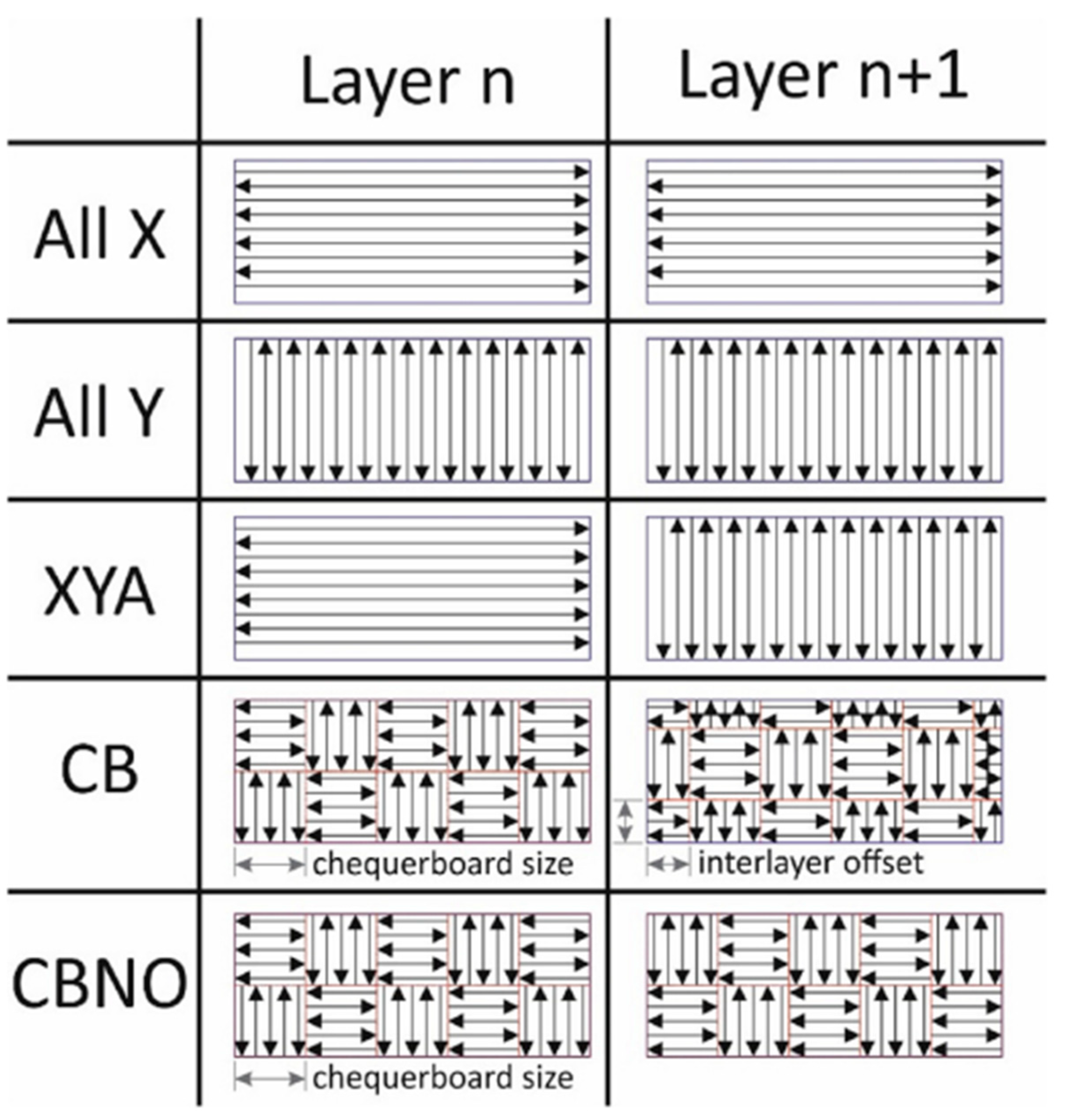
| Scan strategy | The XY alternating scanning strategy is the most effective multi-dimensional scanning strategy for minimizing residual stress. | Continuous deposition is more likely to induce warpage and distortion in parts compared to alternating scanning strategy. | [23,26,65,66] |
| Powder feeding rate | A high powder feeding rate reduces the formation of RS in AM metals. | A high powder feeding rate lowers the energy input in the melt pool, thus an even temperature distribution is achieved. | [64] |
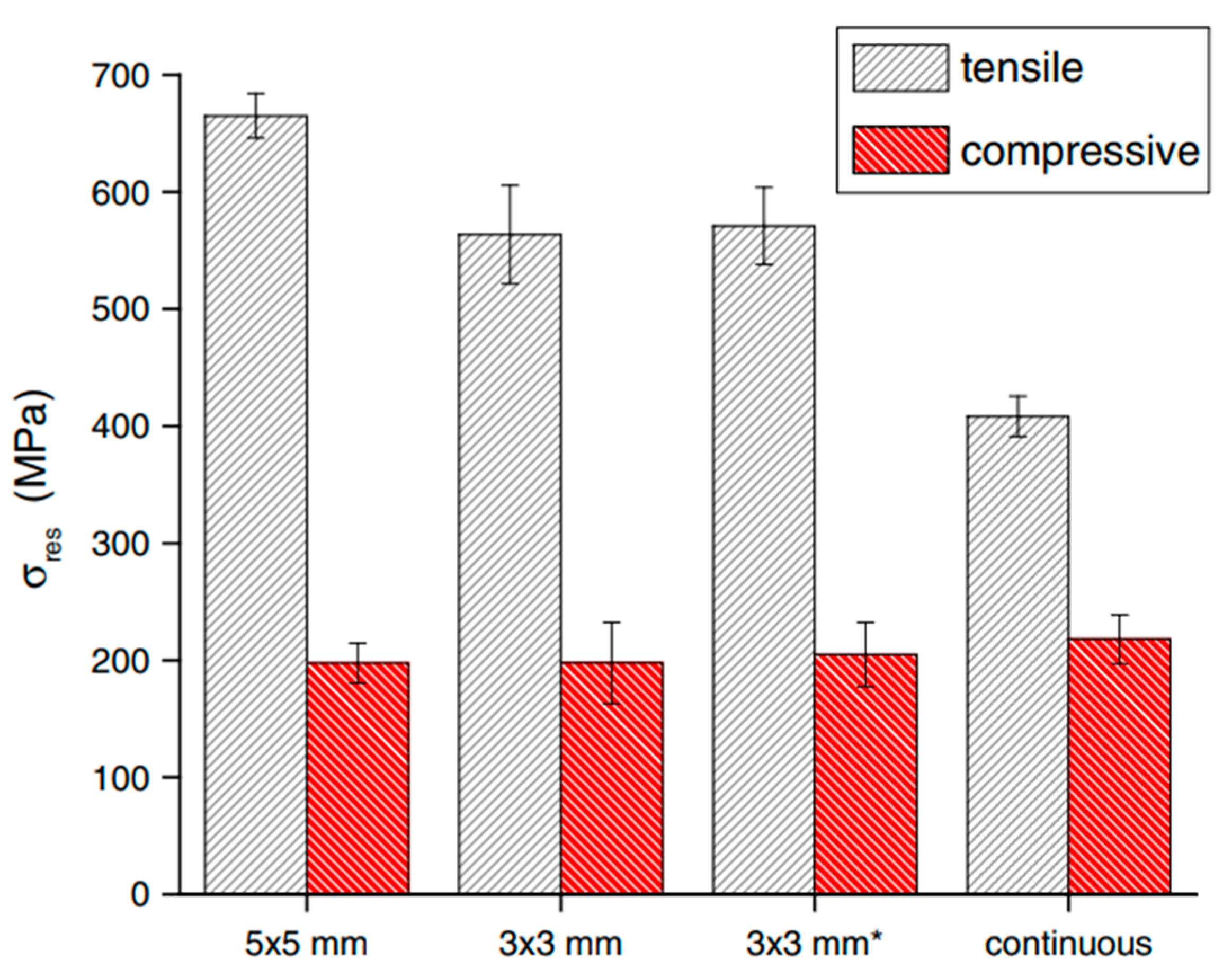
| Scan island size | As island size increases, the RS in metals also increases. | Smaller scan vectors result in lower residual stresses because shorter scan vectors reduce the curling angle in bridge-like specimens. | [67,68] |
| Post-Processing | Effects | Remarks | References |
|---|---|---|---|
| Post-heat treatment | Heat treatment significantly improves the fatigue life of AM parts, and reduces the formation of RS if appropriate heat treatment temperature is determined. The ductility of the specimens also gets increased. | Heat treatment at 400 °C for 2 h resulted in a 53.7% reduction in residual stress [81]. However, the yield strength and UTS of parts are lowered if heat treatment is carried out at very high temperature. | [81,82,83,84] |
| Laser shock peening (LSP) | LSP is applied to change the tensile residual stress to compressive residual stress. LSP improves the fatigue life of parts and increases the micro-hardness with grain refinement. | When LSP was applied, the tensile RS was changed to compressive residual stress with magnitude of 100 MPa. The yield strength was improved by 72% [90]. | [85,86,87,88,89] |
| Inter-pass rolling | Improves the grain refinement, and reduces the RS formation. | Inter-pass rolling reduces the anisotropy present in the microstructure due to the induced plastic deformation. Hence, the mechanical properties are also improved. | [102,103] |
| Hot isostatic pressing (HIP) | HIP treatment induces microstructural changes in AM metals, which reduces the porosity and improves the fatigue life of parts. HIP treatment at elevated temperature can reduces the formation of RS in metals. | HIP treatment can improve the fatigue strength limit of parts by more than 100% compared to non-treated and stress-relieved specimens [104]. | [105,106] |
| Ultrasonic nanocrystal surface modification (UNSM) | UNSM can significantly improves the fatigue performance of metal parts. In this process, parts are subjected to plastic strain, resulting in grain refinement, work hardening, and formation of compressive residual stress. | The UNSM process helps in converting the tensile residual stress to compressive residual stress, which improves the fatigue life of parts. | [107,108] |
| Shot peening | Shot peening has similar effect to LSP. In shot peening, compressive residual stress is induced, replacing the tensile residual stress. | Compressive residual stress is beneficial for improving the fatigue life of parts. | [109,110] |
Disclaimer/Publisher’s Note: The statements, opinions and data contained in all publications are solely those of the individual author(s) and contributor(s) and not of MDPI and/or the editor(s). MDPI and/or the editor(s) disclaim responsibility for any injury to people or property resulting from any ideas, methods, instructions or products referred to in the content. |
© 2023 by the authors. Licensee MDPI, Basel, Switzerland. This article is an open access article distributed under the terms and conditions of the Creative Commons Attribution (CC BY) license (https://creativecommons.org/licenses/by/4.0/).
Share and Cite
Bastola, N.; Jahan, M.P.; Rangasamy, N.; Rakurty, C.S. A Review of the Residual Stress Generation in Metal Additive Manufacturing: Analysis of Cause, Measurement, Effects, and Prevention. Micromachines 2023, 14, 1480. https://doi.org/10.3390/mi14071480
Bastola N, Jahan MP, Rangasamy N, Rakurty CS. A Review of the Residual Stress Generation in Metal Additive Manufacturing: Analysis of Cause, Measurement, Effects, and Prevention. Micromachines. 2023; 14(7):1480. https://doi.org/10.3390/mi14071480
Chicago/Turabian StyleBastola, Nabin, Muhammad P. Jahan, Nithin Rangasamy, and Chandra Sekhar Rakurty. 2023. "A Review of the Residual Stress Generation in Metal Additive Manufacturing: Analysis of Cause, Measurement, Effects, and Prevention" Micromachines 14, no. 7: 1480. https://doi.org/10.3390/mi14071480