

A Design of Quad-Element Dual-Band MIMO Antenna for 5G Application
Abstract
:1. Introduction
2. Geometry and Design of Antenna
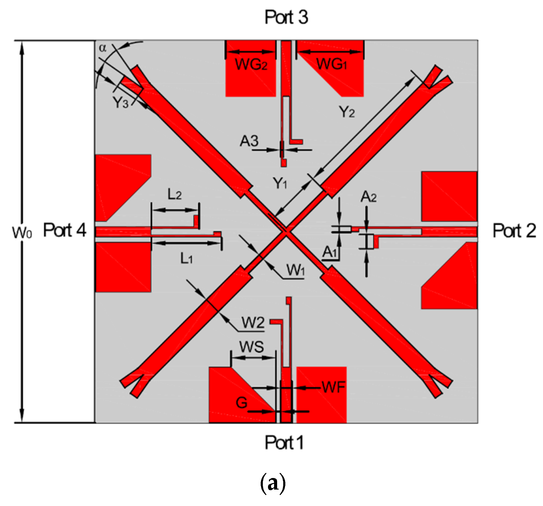
2.1. Antenna Geometry
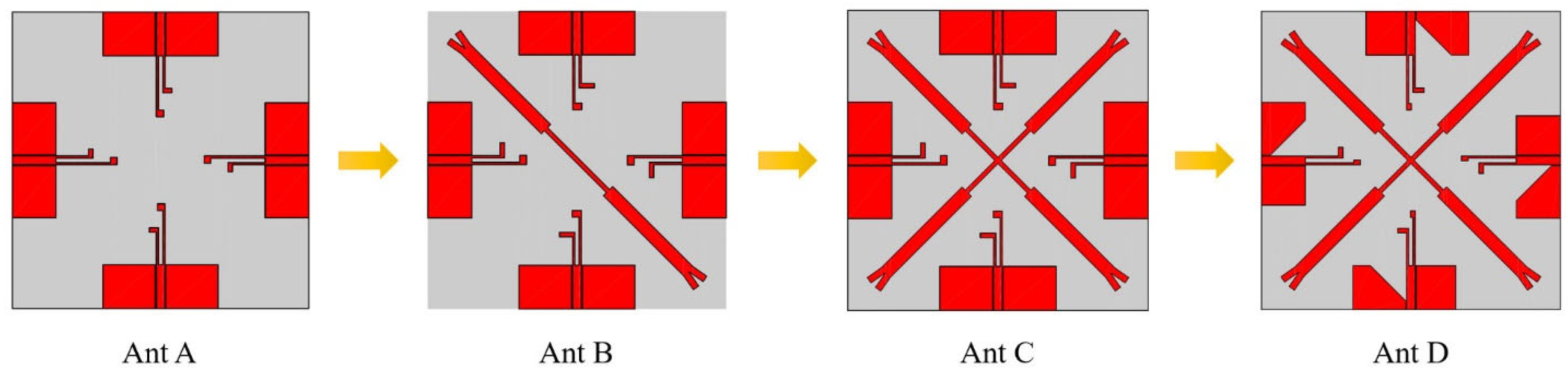
2.2. Design Process
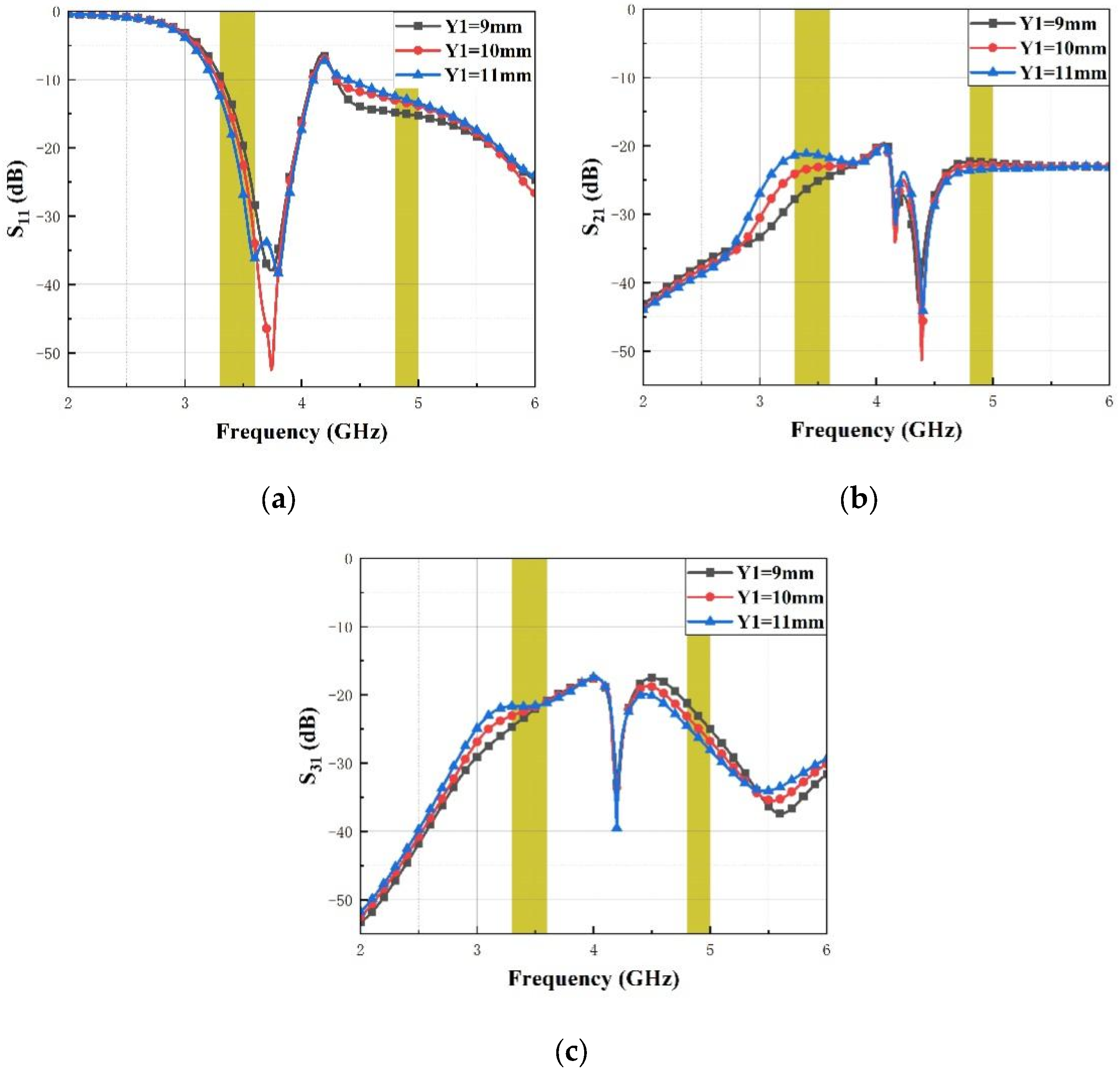
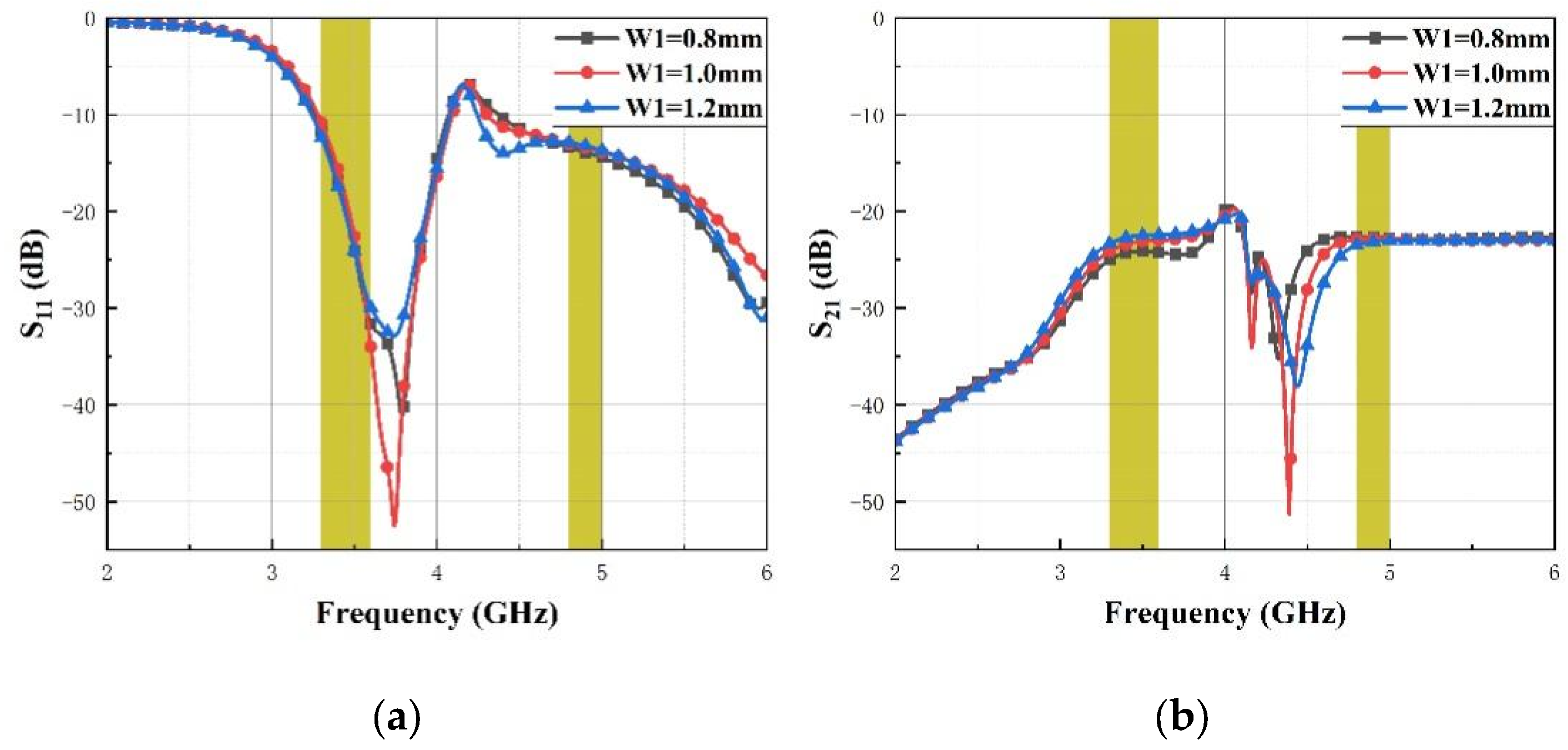
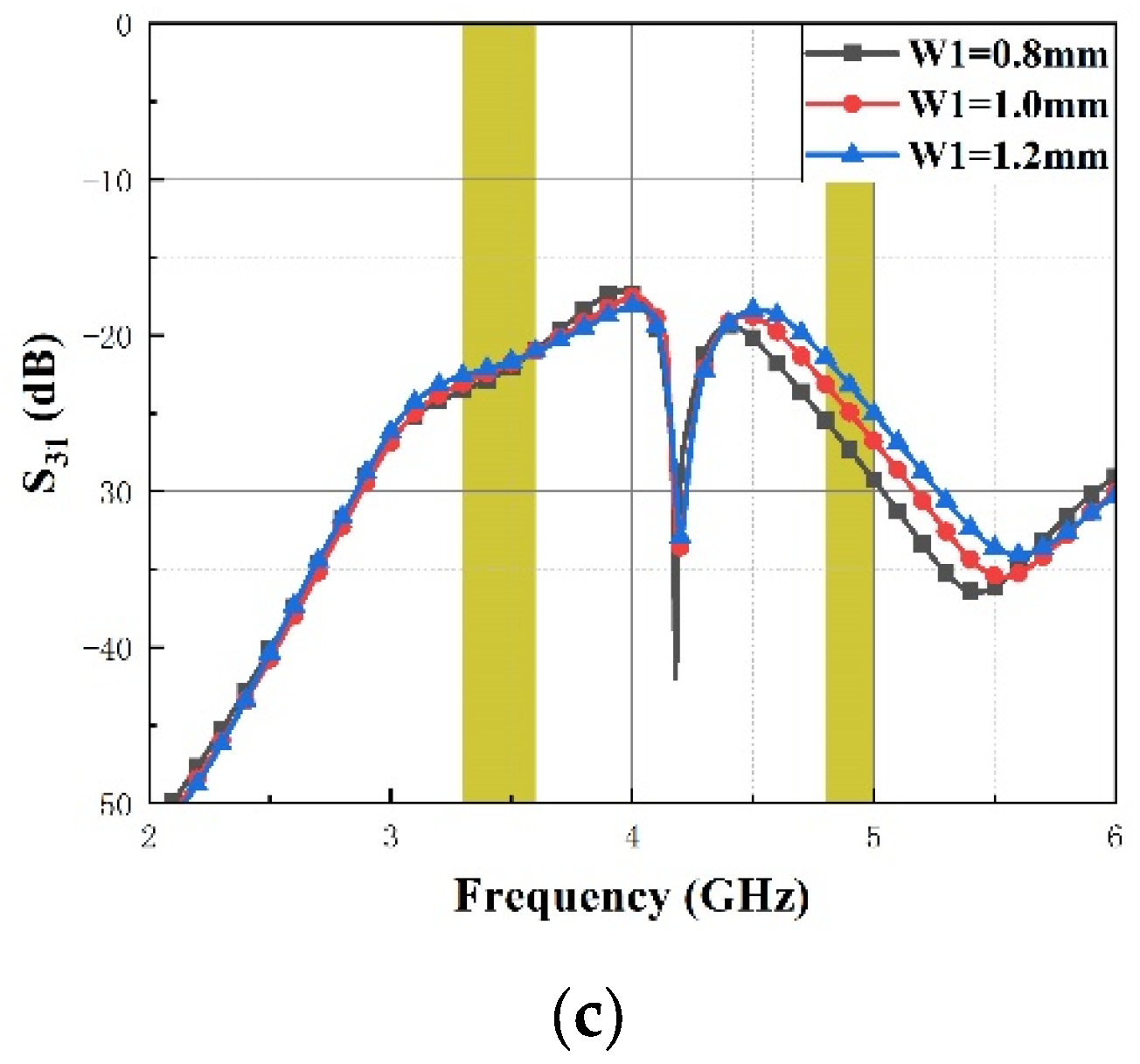
2.3. Parametric Study
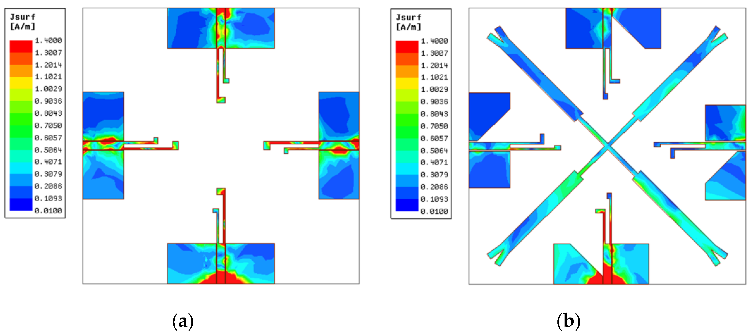
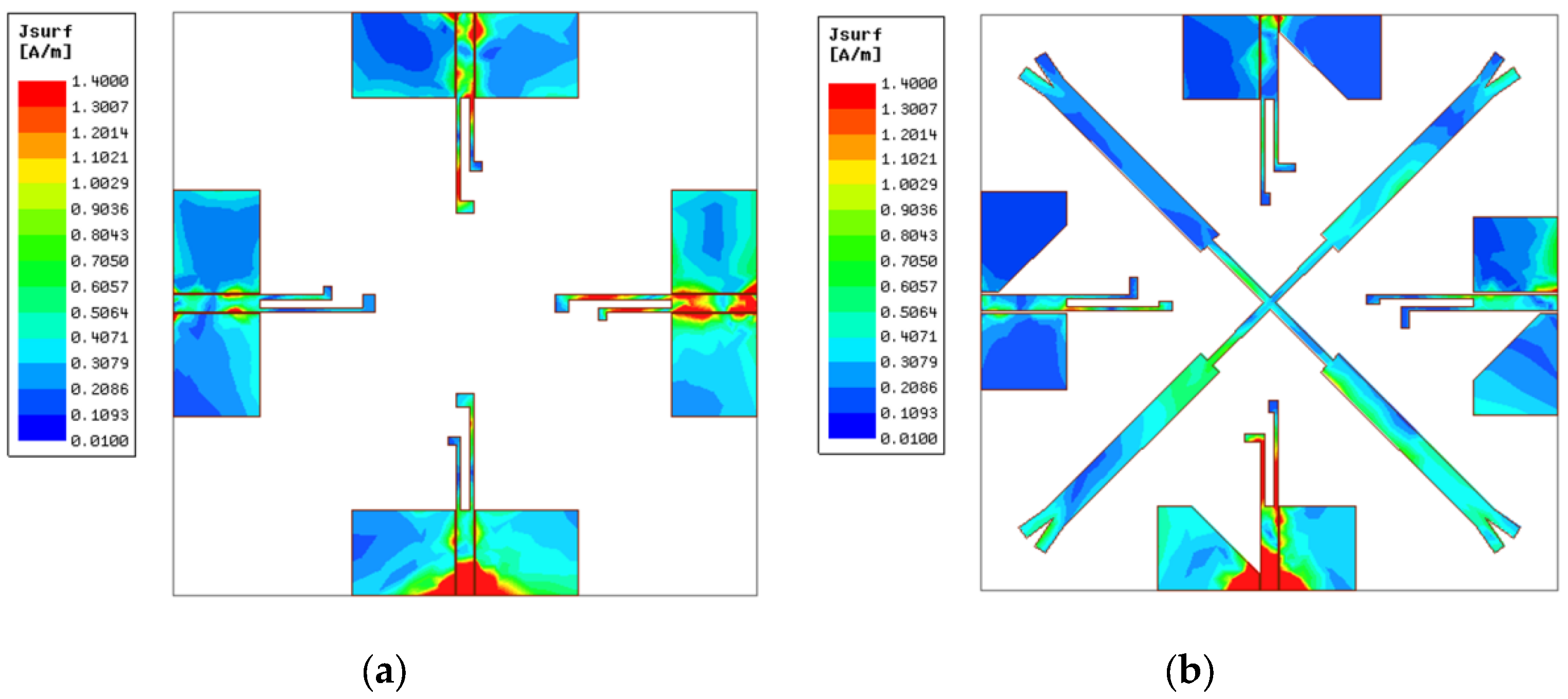
2.4. Current Distribution
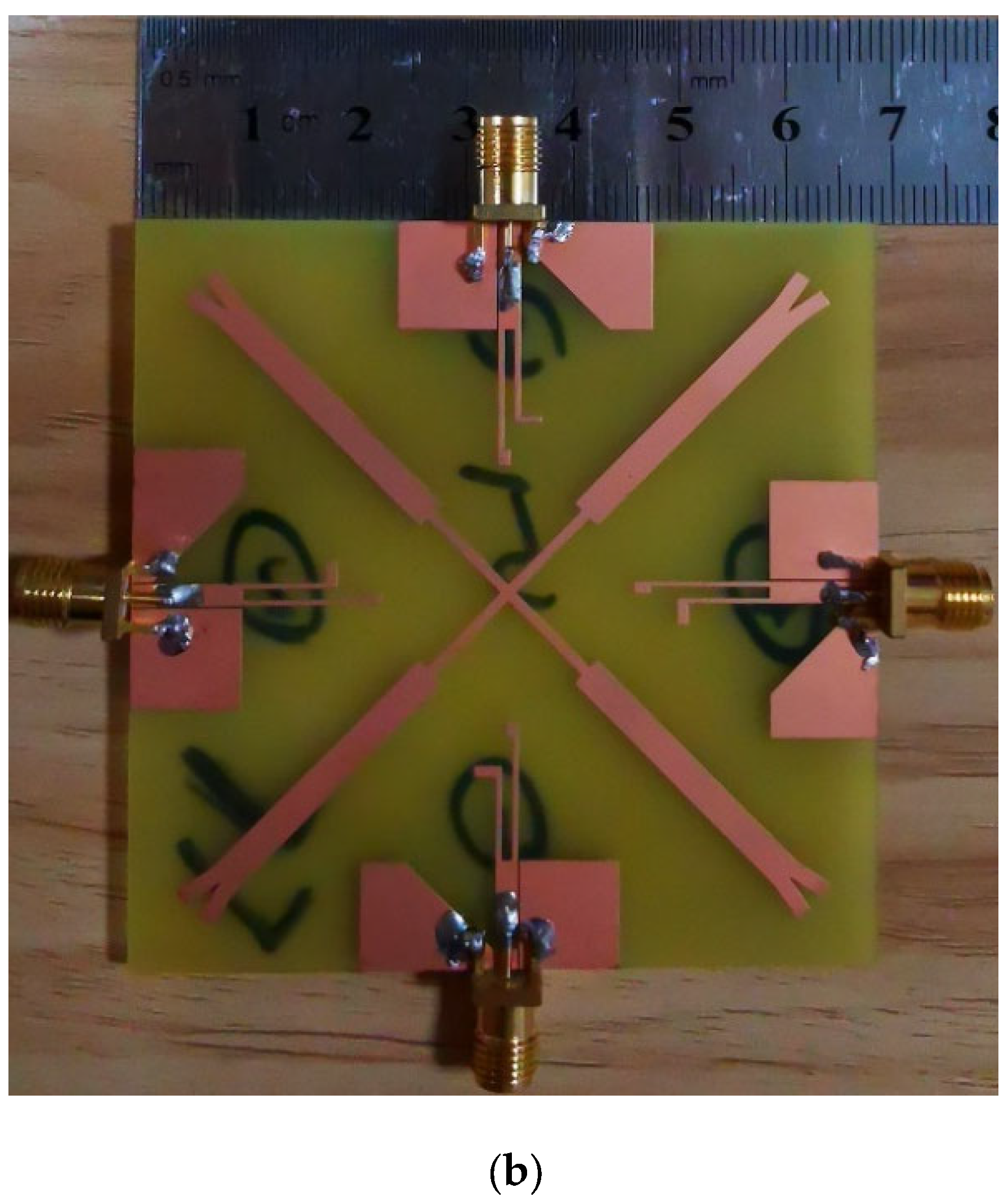
3. Experiment Verification
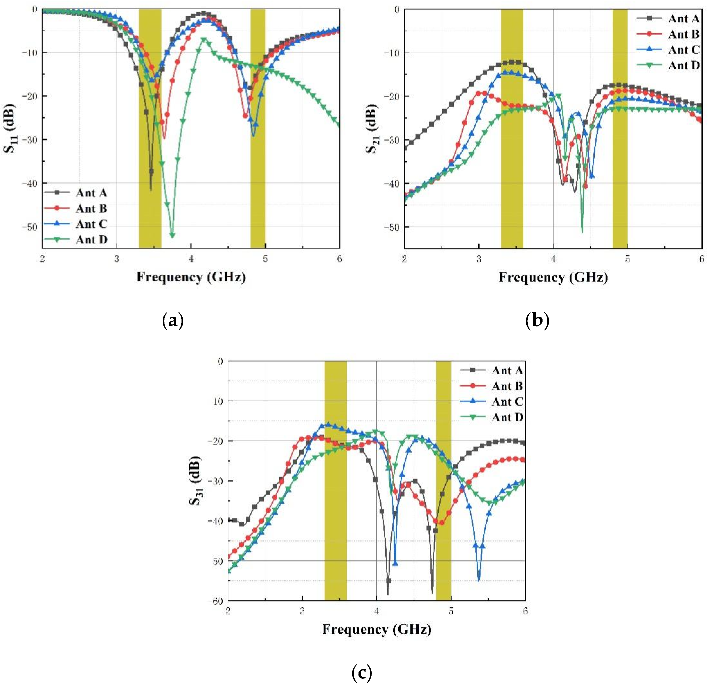
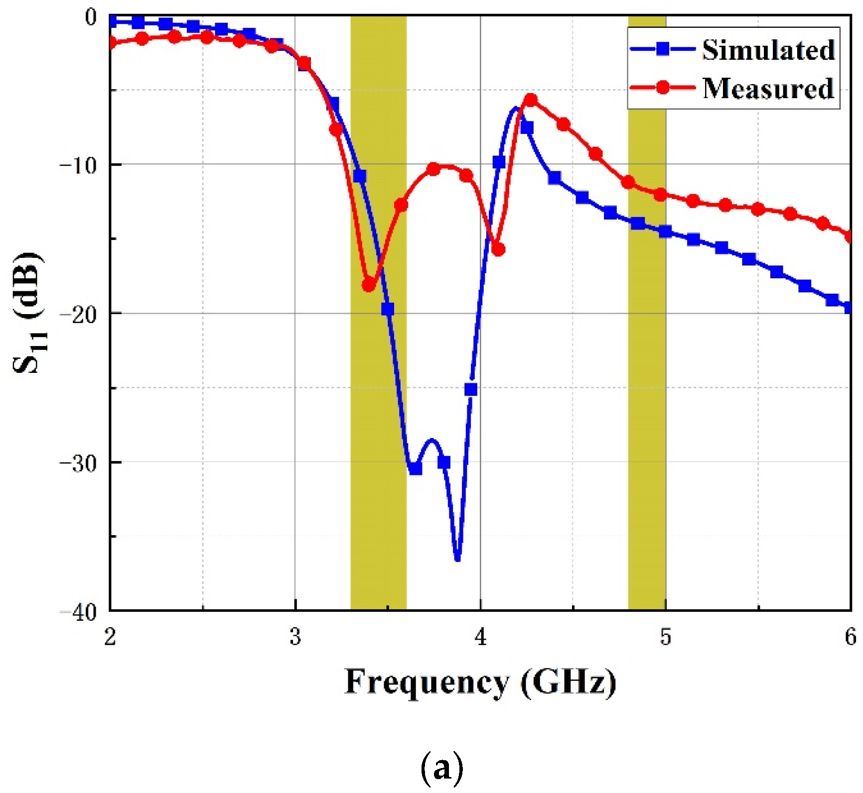
3.1. S-Parameter
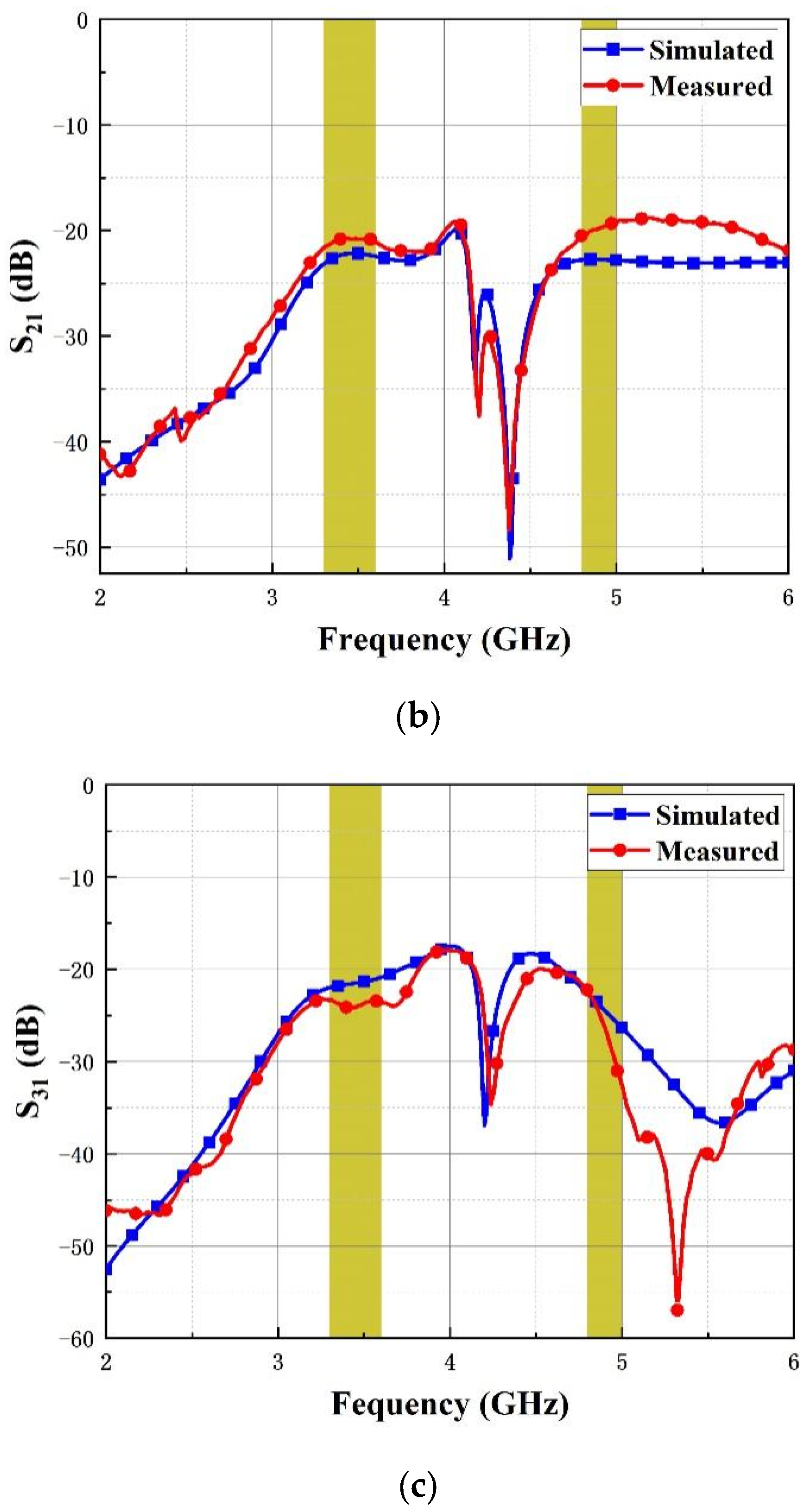
3.2. Radiation Patterns
4. Diversity Performance
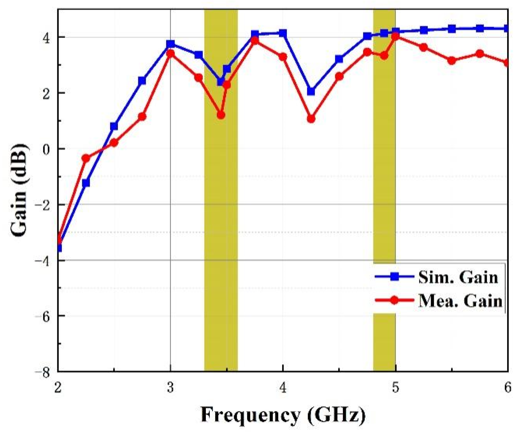
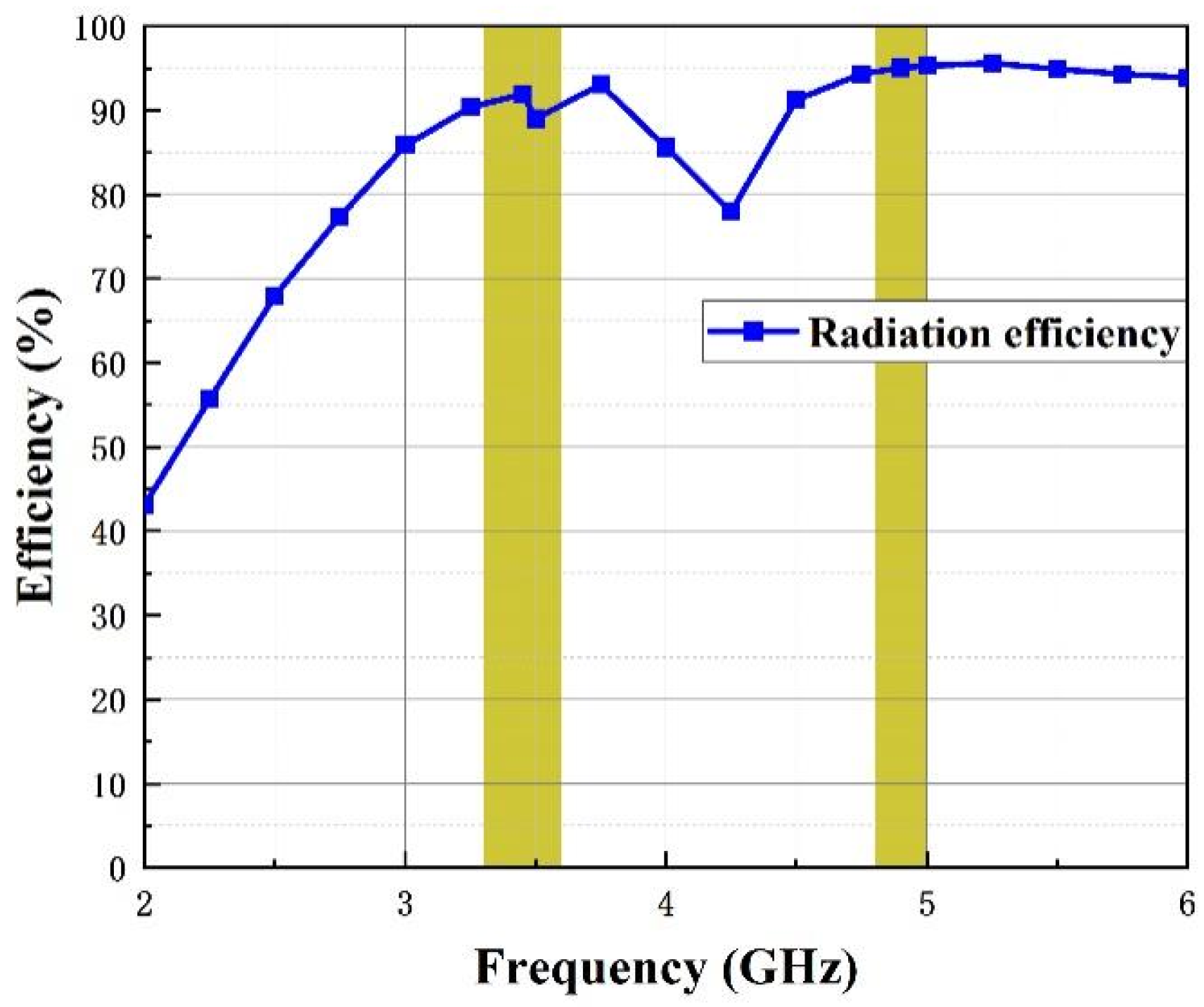
4.1. Gain and Efficiency
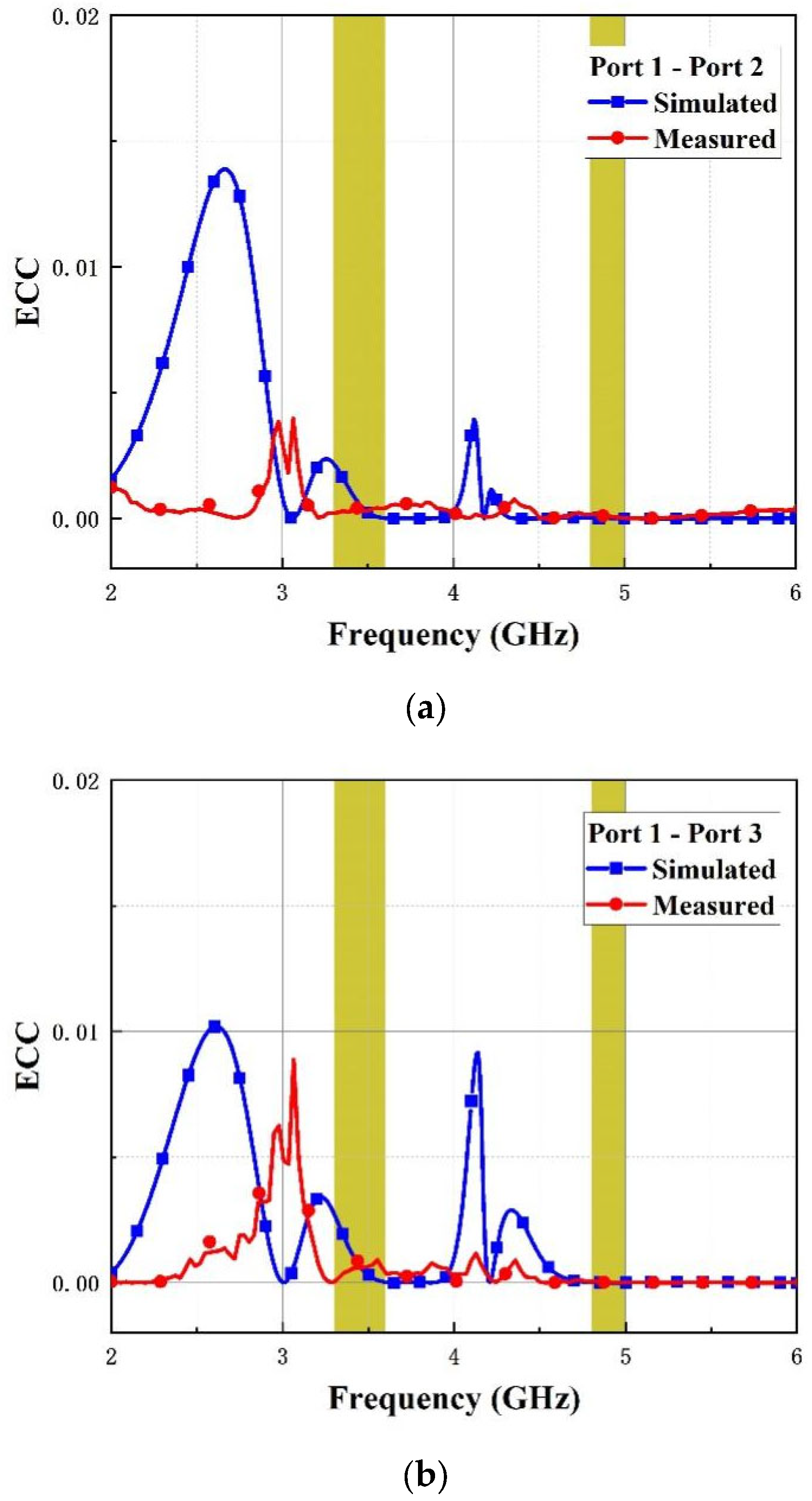
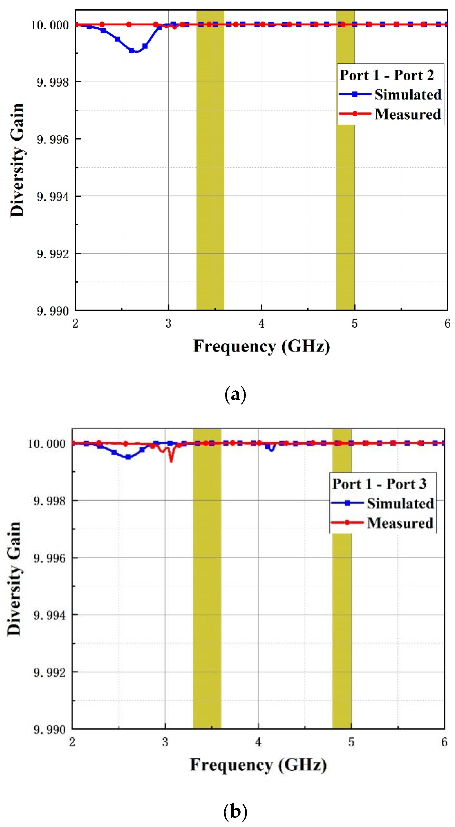
4.2. ECC and DG
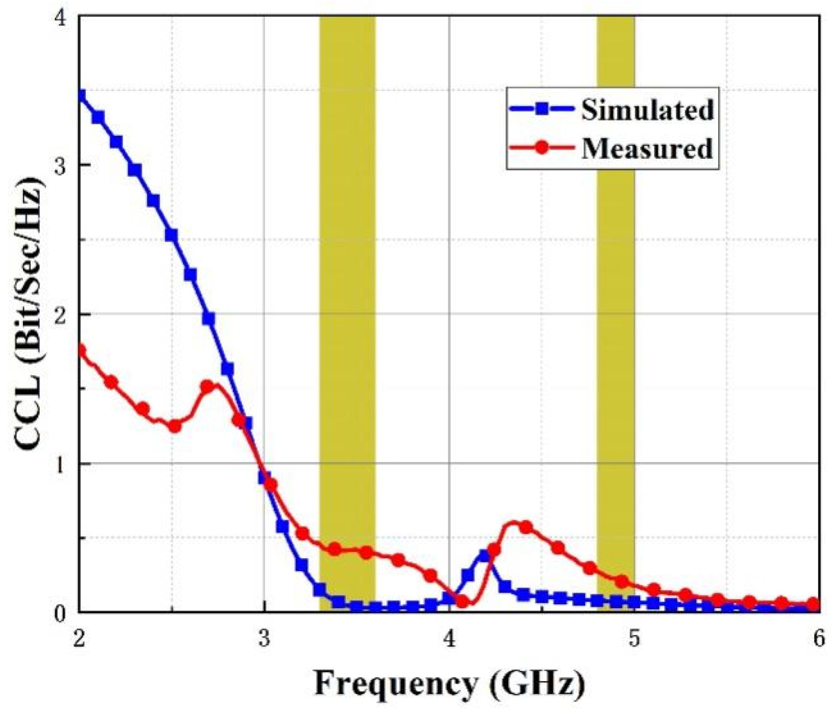
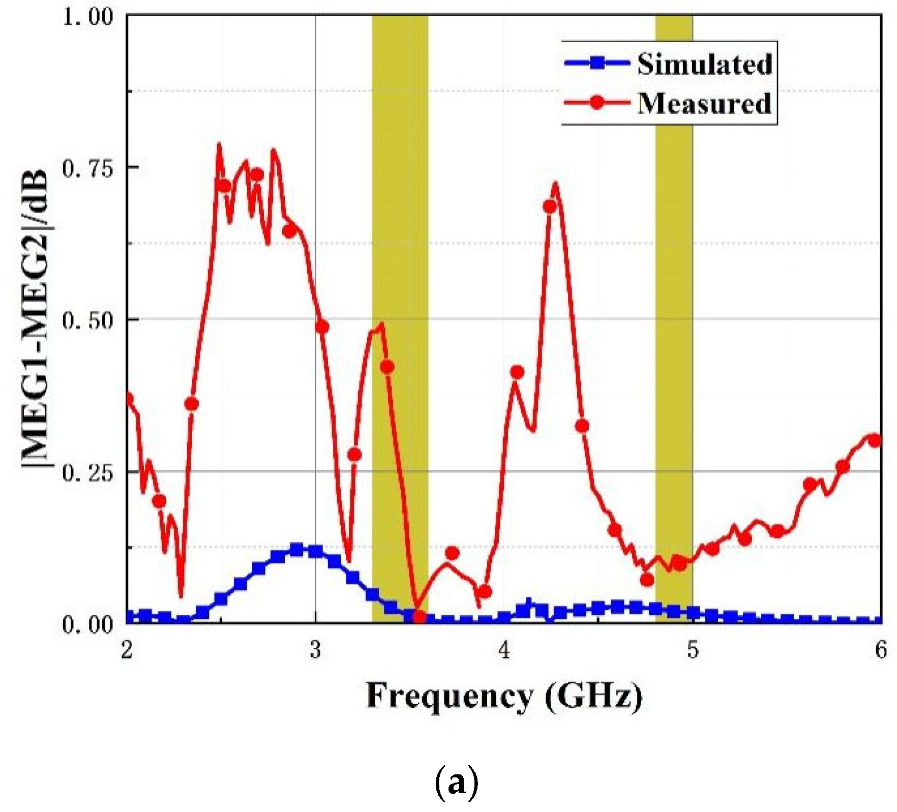
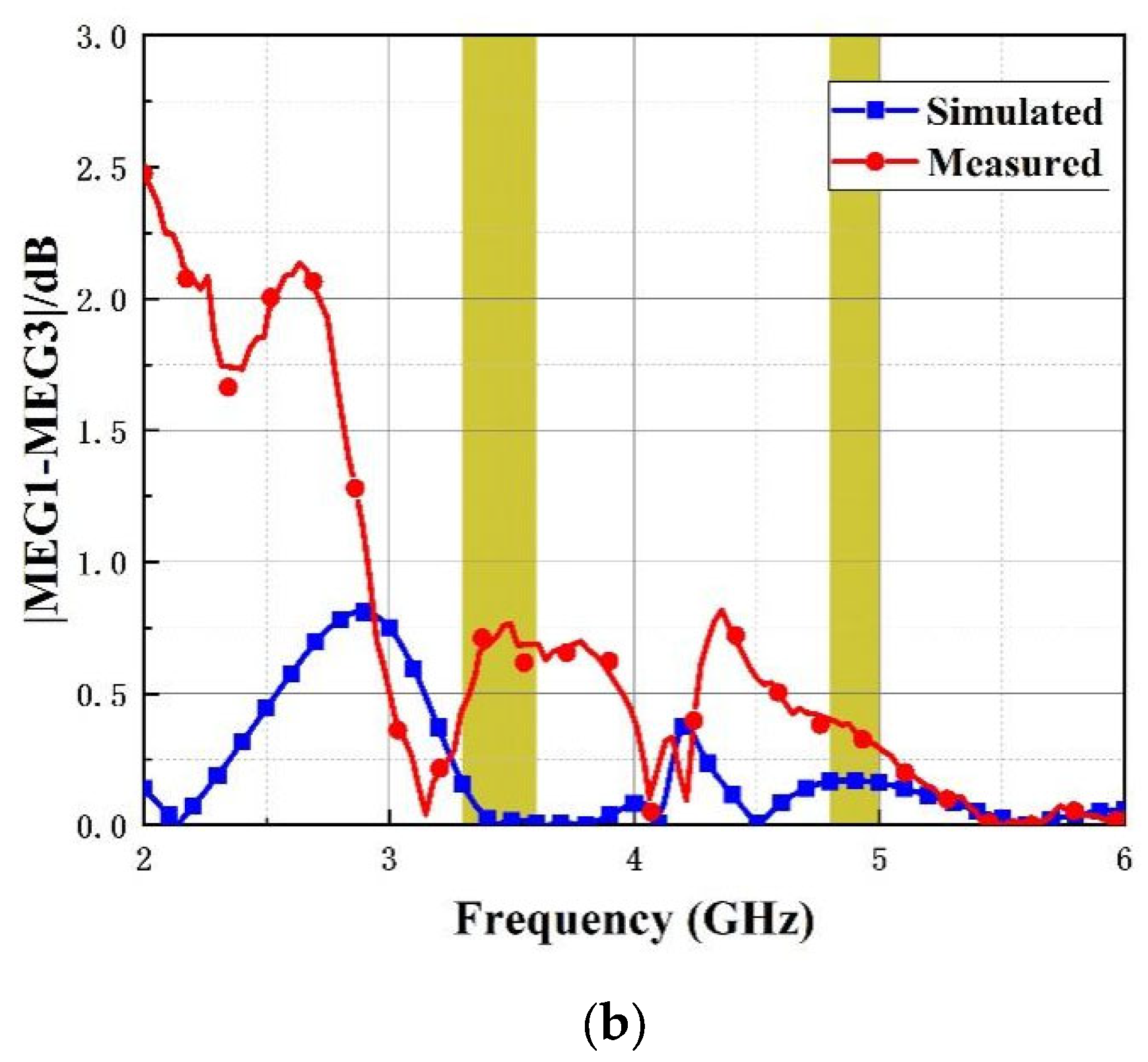
4.3. CCL and MEG
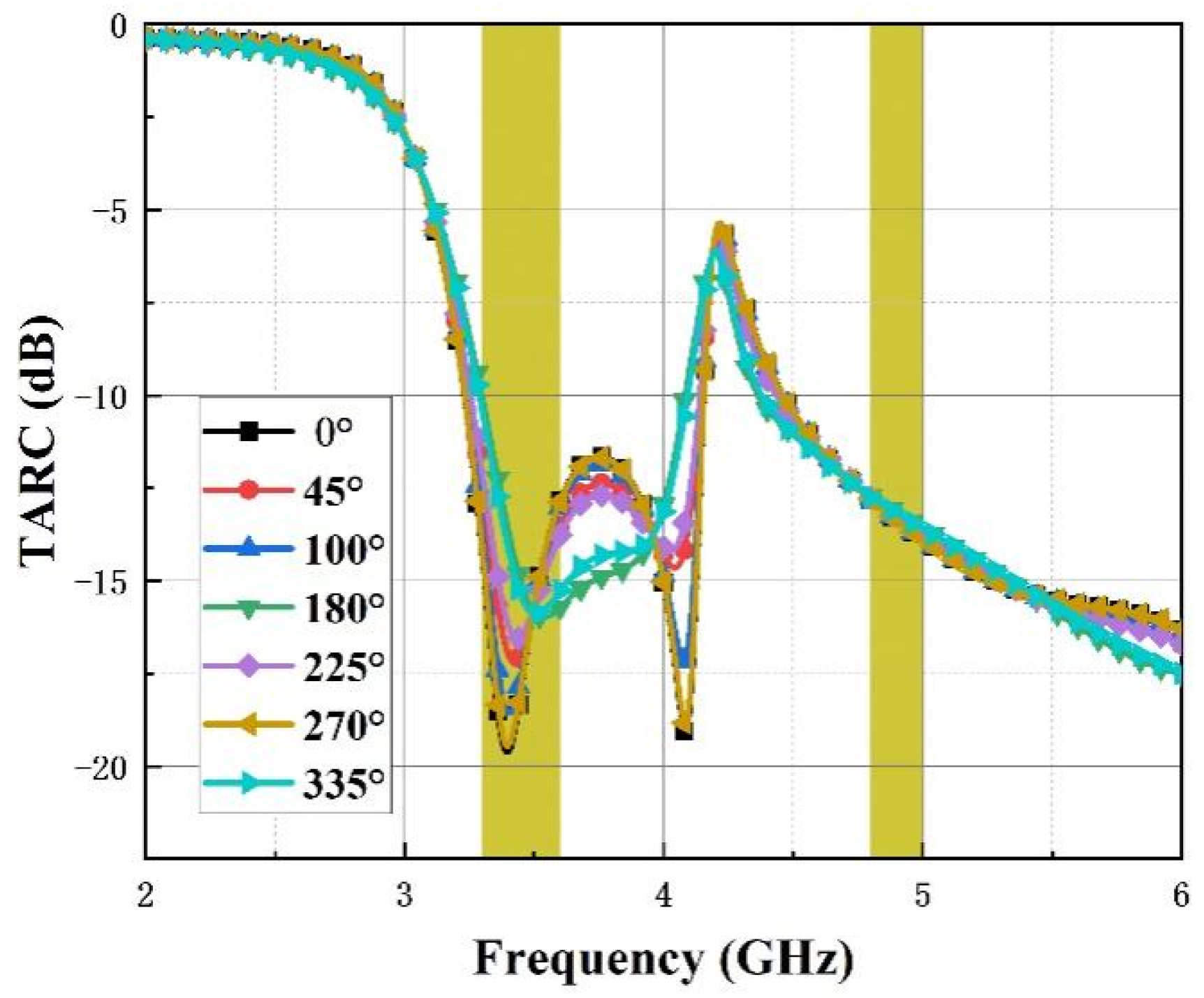
4.4. TARC (Total Active Reflection Coefficient)
4.5. Performance Comparison
5. Conclusions
Author Contributions
Funding
Conflicts of Interest
References
- Ramachandran, A.; Mathew, S.; Rajan, V.; Kesavath, V. A compact triband quad-element MIMO antenna using SRR ring for high isolation. IEEE Antennas Wirel. Propag. Lett. 2016, 16, 1409–1412. [Google Scholar] [CrossRef]
- Li, M.; Zhong, B.G.; Cheung, S.W. Isolation enhancement for MIMO patch antennas using near-field resonators as coupling-mode transducers. IEEE Trans. Antennas Propag. 2018, 67, 755–764. [Google Scholar] [CrossRef]
- Anitha, R.; Vinesh, P.V.; Prakash, K.C.; Mohanan, P.; Vasudevan, K. A compact quad element slotted ground wideband antenna for MIMO applications. IEEE Trans. Antennas Propag. 2016, 64, 4550–4553. [Google Scholar] [CrossRef]
- Zhang, S.; Pedersen, G.F. Mutual coupling reduction for UWB MIMO antennas with a wideband neutralization line. IEEE Antennas Wirel. Propag. Lett. 2015, 15, 166–169. [Google Scholar] [CrossRef]
- Peng, H.L.; Tao, R.; Yin, W.Y.; Mao, J.F. A novel compact dual-band antenna array with high isolations realized using the neutralization technique. IEEE Trans. Antennas Propag. 2012, 61, 1956–1962. [Google Scholar] [CrossRef]
- Zhao, X.; Riaz, S. A dual-band frequency reconfigurable MIMO patch-slot antenna based on reconfigurable microstrip feedline. IEEE Access 2018, 6, 41450–41457. [Google Scholar] [CrossRef]
- Nandi, S.; Mohan, A. A compact dual-band MIMO slot antenna for WLAN applications. IEEE Antennas Wirel. Propag. Lett. 2017, 16, 2457–2460. [Google Scholar] [CrossRef]
- Rekha, V.S.D.; Pardhasaradhi, P.; Madhav, B.T.P.; Devi, Y.U. Dual band notched orthogonal 4-element MIMO antenna with isolation for UWB applications. IEEE Access 2020, 8, 145871–145880. [Google Scholar] [CrossRef]
- Raheja, D.K.; Kanaujia, B.K.; Kumar, S. Compact four-port MIMO antenna on slotted-edge substrate with dual-band rejection characteristics. Int. J. RF Microw. Comput.-Aided Eng. 2019, 29, e21756. [Google Scholar] [CrossRef]
- Tirado-Méndez, J.A.; Jardón-Aguilar, H.; Rangel-Merino, A.; Vasquez-Toledo, L.A.; Gómez-Villanueva, R. Four ports wideband drop-shaped slot antenna for MIMO applications. J. Electromagn. Waves Appl. 2020, 34, 1159–1179. [Google Scholar] [CrossRef]
- Chen, S.-C.; Wu, M.-K.; Chiang, C.-W.; Lin, M.-S. 3.5-GHz four-element MIMO antenna system for 5G laptops with a large screen-to-body ratio. J. Electromagn. Waves Appl. 2020, 34, 1195–1209. [Google Scholar] [CrossRef]
- Dou, Y.; Chen, Z.; Bai, J.; Cai, Q.; Liu, G. Two-port CPW-fed dual-band MIMO antenna for IEEE 802.11 a/b/g applications. Int. J. Antennas Propag. 2021, 2021, 5572887. [Google Scholar] [CrossRef]
- Chen, S.C.; Chiang, C.W.; Hsu, C.I.G. Compact four-element MIMO antenna system for 5G laptops. IEEE Access 2019, 7, 186056–186064. [Google Scholar] [CrossRef]
- Ren, Z.; Zhao, A. Dual-band MIMO antenna with compact self-decoupled antenna pairs for 5G mobile applications. IEEE Access 2019, 7, 82288–82296. [Google Scholar] [CrossRef]
- Xi, S.; Huang, J.; Chen, B.; Liu, G. A compact dual-band multi-input multi-output antenna for 5G/WLAN/Bluetooth applications. Microw. Opt. Technol. Lett. 2022, 64, 325–330. [Google Scholar] [CrossRef]
- Mchbal, A.; Touhami, N.A.; Elftouh, H.; Dkiouak, A. Coupling reduction using a novel circular ripple-shaped decoupling mechanism in a four-element UWB MIMO antenna design. J. Electromagn. Waves Appl. 2020, 34, 1647–1666. [Google Scholar] [CrossRef]
- Sharma, P.; Tiwari, R.N.; Singh, P.; Kanaujia, B.K. Dual-band trident shaped MIMO antenna with novel ground plane for 5G applications. AEU-Int. J. Electron. Commun. 2022, 155, 154364. [Google Scholar] [CrossRef]
- Boukarkar, A.; Lin, X.Q.; Jiang, Y.; Nie, L.Y.; Mei, P.; Yu, Y.Q. A miniaturized extremely close-spaced four-element dual-band MIMO antenna system with polarization and pattern diversity. IEEE Antennas Wirel. Propag. Lett. 2017, 17, 134–137. [Google Scholar] [CrossRef]
- Ayinala, K.D.; Sahu, P.K. Isolation enhanced compact dual-band quad-element MIMO antenna with simple parasitic decoupling elements. AEU-Int. J. Electron. Commun. 2021, 142, 154013. [Google Scholar] [CrossRef]
- Pandit, S.; Mohan, A.; Ray, P. A compact four-element MIMO antenna for WLAN applications. Microw. Opt. Technol. Lett. 2018, 60, 289–295. [Google Scholar] [CrossRef]
- Kumar, A.; Ansari, A.Q.; Kanaujia, B.K.; Kishor, J. High isolation compact four-port MIMO antenna loaded with CSRR for multiband applications. Frequenz 2018, 72, 415–427. [Google Scholar] [CrossRef]
- Malviya, L.; Panigrahi, R.K.; Kartikeyan, M.V. Four element planar MIMO antenna design for long-term evolution operation. IETE J. Res. 2018, 64, 367–373. [Google Scholar] [CrossRef]


| Ref | Size (mm2) | Bandwidth (GHz) | Isolation (dB) | ECC | No. of Element | Feeder Method |
|---|---|---|---|---|---|---|
| [12] | 2500 | (2.25–3.15) 33.3%, (4.89–5.95) 19.6% | 15 | 0.01 | 2 | CPW |
| [15] | 2162.25 | (2.28–2.7)16.9%, (4.96–6.1) 20.6% | 15 | 0.06 | 2 | Microstrip feed |
| [17] | 1587.2 | (2.99–3.61) 18.8%, (4.53–4.92) 8.3% | 16 | 0.002 | 2 | Microstrip feed |
| [18] | 1681 | (3.471–3.529)1.7%, (5.678–5.721) 0.8% | 18.4 | 0.08 | 4 | Microstrip feed |
| [19] | 1156 | (3.35–3.75) 11.2%, (5.6–6.05) 7.7% | 19 | 0.01 | 4 | Microstrip feed |
| Prop. | 4624 | (3.28–4.15) 23.4%, (4.69–6.01) 24.7% | 19 | 0.0025 | 4 | CPW |
Disclaimer/Publisher’s Note: The statements, opinions and data contained in all publications are solely those of the individual author(s) and contributor(s) and not of MDPI and/or the editor(s). MDPI and/or the editor(s) disclaim responsibility for any injury to people or property resulting from any ideas, methods, instructions or products referred to in the content. |
© 2023 by the authors. Licensee MDPI, Basel, Switzerland. This article is an open access article distributed under the terms and conditions of the Creative Commons Attribution (CC BY) license (https://creativecommons.org/licenses/by/4.0/).
Share and Cite
Shi, C.; Zhao, Z.; Du, C. A Design of Quad-Element Dual-Band MIMO Antenna for 5G Application. Micromachines 2023, 14, 1316. https://doi.org/10.3390/mi14071316
Shi C, Zhao Z, Du C. A Design of Quad-Element Dual-Band MIMO Antenna for 5G Application. Micromachines. 2023; 14(7):1316. https://doi.org/10.3390/mi14071316
Chicago/Turabian StyleShi, Chengxin, Zhuolin Zhao, and Chengzhu Du. 2023. "A Design of Quad-Element Dual-Band MIMO Antenna for 5G Application" Micromachines 14, no. 7: 1316. https://doi.org/10.3390/mi14071316