
Enhancement of Feed Source through Three Dimensional Printing


Abstract
:1. Introduction
2. Generation of Wide Band Prototype
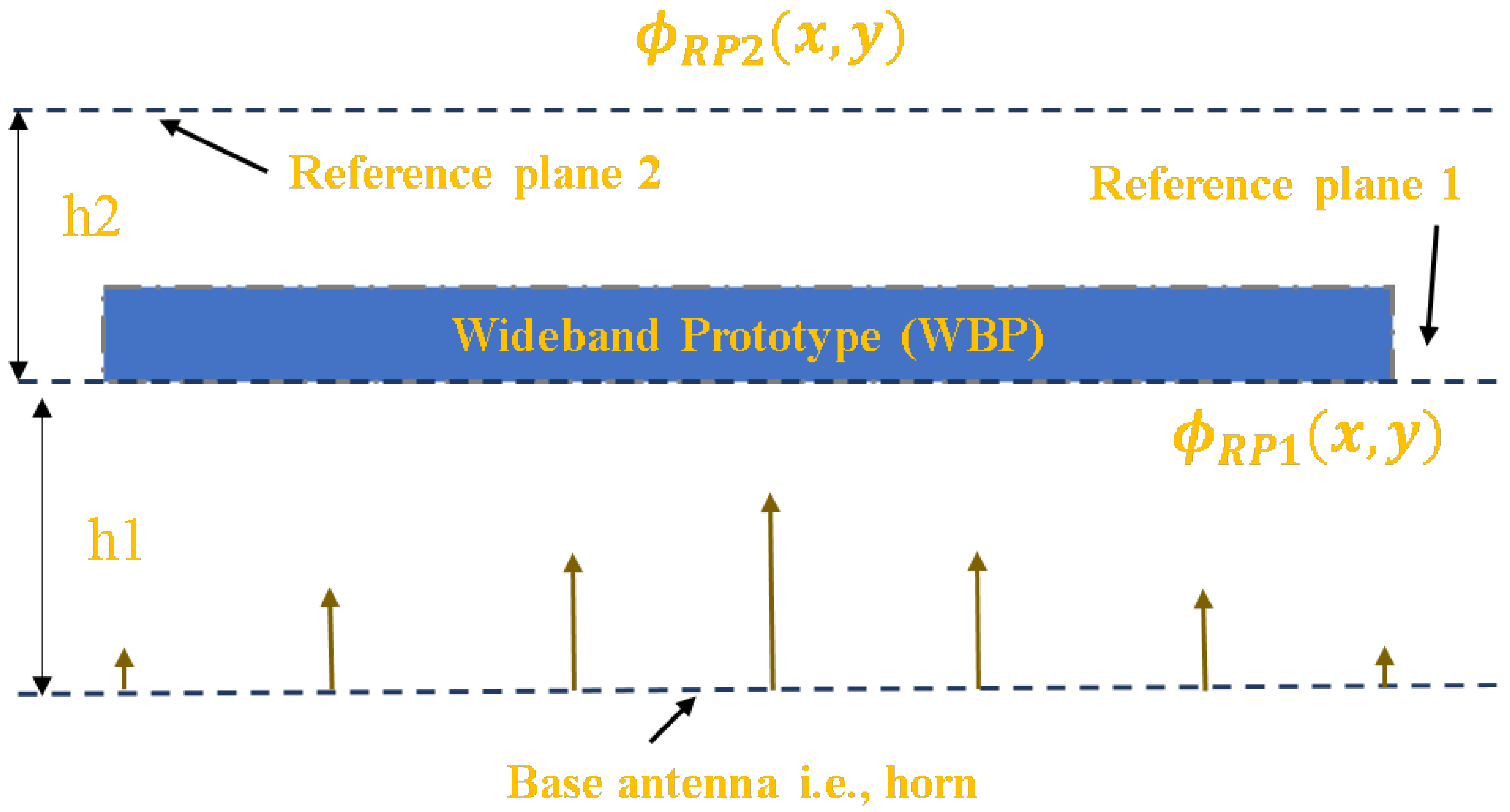
- Step 1:
- Calculate the required phase value at a 0.5 distance above the defined aperture of the horn feed source. Phase values obtained in aperture positions of 3.75 mm, 11.25 mm, 18.75 mm, 26.25 mm, 33.75 mm, 41.25 mm, and 48.75 mm from the center of the aperture are , , , , , , and .
- Step 2:
- Normalize these noted phase values by considering higher phase values above the highest value. Here, we considered and the normalized values obtained were , , , , , , and for defined aperture positions of 3.75 mm, 11.25 mm, 18.75 mm, 26.25 mm, 33.75 mm, 41.25 mm, and 48.75 mm.
- Step 3:
- These normalized phase values are correlated to respective cube sizes from a database prepared with an arrangement of five layers of cubes. The respective cube sizes are 3, 7.5, 7.5 mm in 3.75 mm; 1.5, 7.5, 7.5 mm in 11.25 mm; 3.5, 7.5, 7 mm in 18.75; 3.5, 7.5, 7 mm in 26.25 mm; 2.5, 7.5, 7 mm in 33.75 mm; 1.5, 7.5, 6 mm in 41.25 mm; and 1.5, 7, 2.5 mm in 48.75 mm.
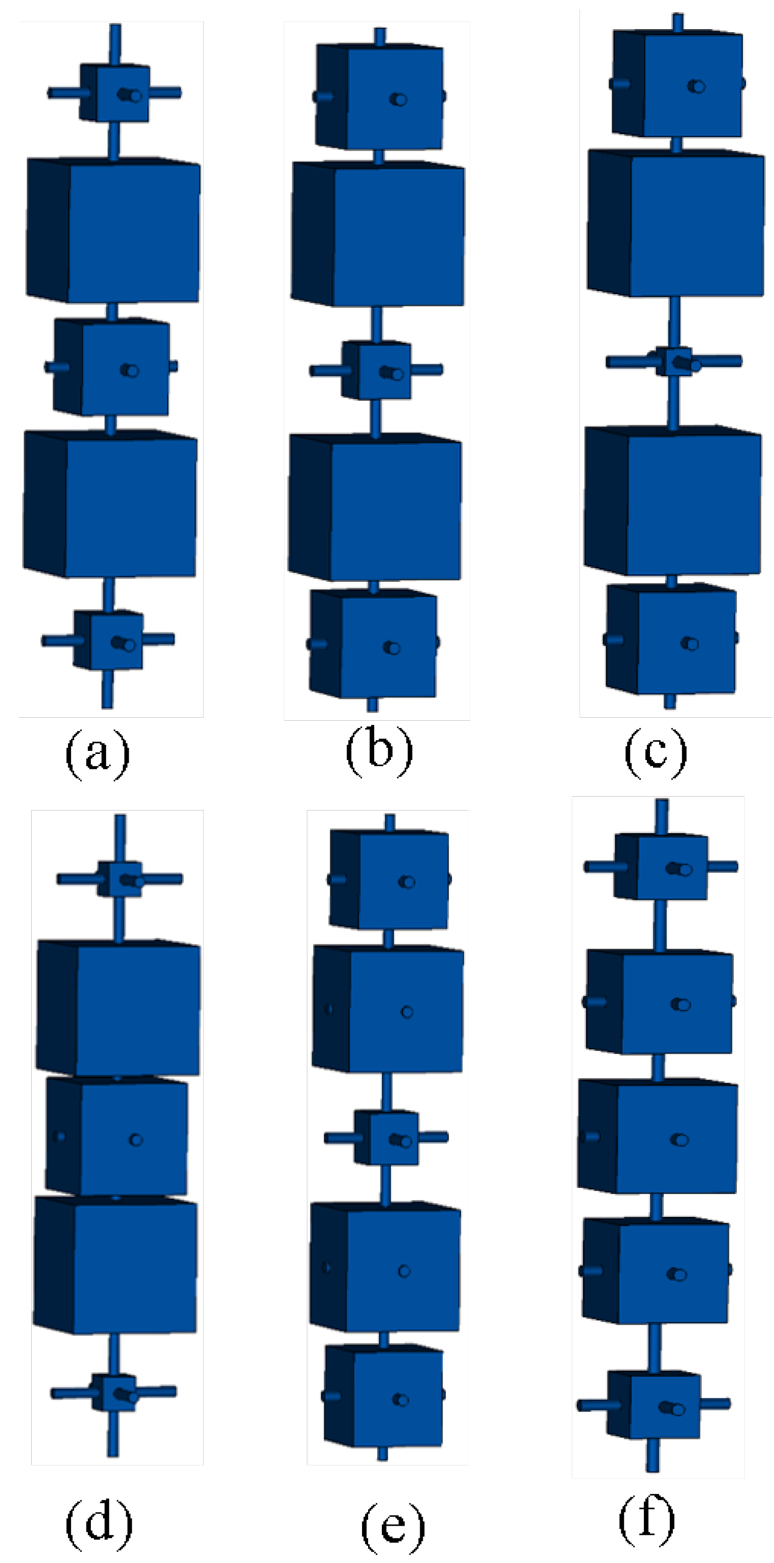
- Step 4:
- Furthermore, cube sizes are tuned to appropriate values to maintain uniformity in the phase distribution at 6.25 mm () above the top face of the WBP, which is based on the prepared five-layer cubes database. Thus, the obtained respective cube sizes are 3, 7.5, 5 mm in 3.75 mm; 5.5, 7.5, 3 mm in 11.25 mm; 5.5, 7.5, 1.5 mm in 18.75; 5.5, 7.5, 1.5 mm in 26.25 mm; 2, 7.5, 6.5 mm in 33.75 mm; 5.5, 7, 3 mm in 41.25 mm; and 3.5, 5.5, 6 mm in 48.75 mm. These cubes are arranged for seven different rounds as Round 1, Round 2, Round 3, Round 4, Round 5, Round 6, and Round 7.
3. Phase Correction as Observed above WBP
4. Result and Discussion
5. Conclusions
Author Contributions
Funding
Data Availability Statement
Acknowledgments
Conflicts of Interest
References
- Kobayashi, H. Horn Antenna. In Analyzing the Physics of Radio Telescopes and Radio Astronomy; IGI Global: Hershey, PA, USA, 2020; pp. 144–177. [Google Scholar]
- Balanis, C.A. Antenna Theory: Analysis and Design; John Wiley & Sons: Hoboken, NJ, USA, 2015. [Google Scholar]
- Shrestha, S.; Choi, D.Y. Characterization of rain specific attenuation and frequency scaling method for satellite communication in South Korea. Int. J. Antennas Propag. 2017, 2017, 8694748. [Google Scholar] [CrossRef]
- Moradi, A.; Mohajeri, F. Side lobe level reduction and gain enhancement of a pyramidal horn antenna in the presence of metasurfaces. IET Microwaves Antennas Propag. 2018, 12, 295–301. [Google Scholar] [CrossRef]
- Agnihotri, I.; Sharma, S.K. Design of a 3D Metal Printed Axial Corrugated Horn Antenna Covering Full Ka-Band. IEEE Antennas Wirel. Propag. Lett. 2020, 19, 522–526. [Google Scholar] [CrossRef]
- Addamo, G.; Peverini, O.A.; Calignano, F.; Manfredi, D.; Paonessa, F.; Virone, G.; Dassano, G. 3-D printing of high-performance feed horns from Ku-to V-bands. IEEE Antennas Wirel. Propag. Lett. 2018, 17, 2036–2040. [Google Scholar] [CrossRef]
- Tak, J.; Kang, D.G.; Choi, J. A lightweight waveguide horn antenna made via 3 D printing and conductive spray coating. Microwave Opt. Technol. Lett. 2017, 59, 727–729. [Google Scholar] [CrossRef]
- Lomakin, K.; Pavlenko, T.; Ankenbrand, M.; Sippel, M.; Ringel, J.; Scheetz, M.; Klemm, T.; Gräf, D.; Helmreich, K.; Franke, J.; et al. Evaluation and characterization of 3-D printed pyramid horn antennas utilizing different deposition techniques for conductive material. IEEE Trans. Components Packag. Manuf. Technol. 2018, 8, 1998–2006. [Google Scholar] [CrossRef]
- Chen, T.; Tang, W.; Mu, J.; Cui, T.J. Microwave metamaterials. Ann. Phys. 2019, 531, 1800445. [Google Scholar] [CrossRef] [Green Version]
- Chen, X.; Ge, Y. Enhancing the radiation performance of a pyramidal horn antenna by loading a subwavelength metasurface. IEEE Access 2017, 5, 20164–20170. [Google Scholar] [CrossRef]
- Wang, L.J.; Chen, Q.H.; Yu, F.L.; Gao, X. High-performance lens antenna using high refractive index metamaterials. Chin. Phys. B 2018, 27, 087802. [Google Scholar] [CrossRef]
- Azad, A.K.; Efimov, A.V.; Ghosh, S.; Singleton, J.; Taylor, A.J.; Chen, H.T. Ultra-thin metasurface microwave flat lens for broadband applications. Appl. Phys. Lett. 2017, 110, 224101. [Google Scholar] [CrossRef] [Green Version]
- Han, J.; Li, L.; Zhang, T.; Xi, R. Control and improvement of antenna gain by using multilayer non-uniform metasurfaces. EPJ Appl. Metamater. 2019, 6, 4. [Google Scholar] [CrossRef]
- Liu, K.; Ge, Y.; Lin, C. A compact wideband high-gain metasurface-lens-corrected conical horn antenna. IEEE Antennas Wirel. Propag. Lett. 2019, 18, 457–461. [Google Scholar] [CrossRef]
- Lalbakhsh, A.; Afzal, M.U.; Hayat, T.; Esselle, K.P.; Mandal, K. All-metal wideband metasurface for near-field transformation of medium-to-high gain electromagnetic sources. Sci. Rep. 2021, 11, 1–9. [Google Scholar] [CrossRef] [PubMed]
- Zhang, B.; Guo, Y.X.; Zirath, H.; Zhang, Y.P. Investigation on 3-D-printing technologies for millimeter-wave and terahertz applications. Proc. IEEE 2017, 105, 723–736. [Google Scholar] [CrossRef]
- Zhang, S.; Cadman, D.; Vardaxoglou, J.Y.C. Additively manufactured profiled conical horn antenna with dielectric loading. IEEE Antennas Wirel. Propag. Lett. 2018, 17, 2128–2132. [Google Scholar] [CrossRef] [Green Version]
- Hoel, K.V.; Ignatenko, M.; Kristoffersen, S.; Lier, E.; Filipovic, D.S. 3-D printed monolithic grin dielectric-loaded double-ridged horn antennas. IEEE Trans. Antennas Propag. 2019, 68, 533–539. [Google Scholar] [CrossRef]
- Shrestha, S.; Baba, A.A.; Abbas, S.M.; Asadnia, M.; Hashmi, R.M. A Horn Antenna Covered with a 3D-Printed Metasurface for Gain Enhancement. Electronics 2021, 10, 119. [Google Scholar] [CrossRef]
- Shrestha, S.; Zahra, H.; Abbasi, M.A.B.; Asadnia, M.; Abbas, S.M. Increasing the directivity of resonant cavity antennas with nearfield transformation meta-structure realized with stereolithograpy. Electronics 2021, 10, 333. [Google Scholar] [CrossRef]
- Shrestha, S.; Zahra, H.; Abbas, S.M.; Kiyani, A.; Mohamadzade, B.; Asadnia, M. Generation of Beam Tilt through Three-Dimensional Printed Surface. Electronics 2021, 10, 3174. [Google Scholar] [CrossRef]
- Shrestha, S.; Zahra, H.; Kiyani, A.; Asadnia, M.; Abbas, S.M.; Mahmoud, A. Miniaturized Wideband Antenna Prototype Operating over the Ku-Band. Micromachines 2022, 13, 471. [Google Scholar] [CrossRef]
- Shrestha, S.; Abbas, S.M.; Asadnia, M.; Esselle, K.P. Steering of Beam Using Cylindrical Arrangements in a Metallic Parallel Plates Structure Operating over Ku-Band. Appl. Sci. 2022, 12, 6074. [Google Scholar] [CrossRef]
- Shrestha, S.; Abbas, S.M.; Asadnia, M.; Esselle, K.P. Realization of Three Dimensional Printed Multi Layer Wide Band Prototype. IEEE Access 2022, 10, 130944–130954. [Google Scholar] [CrossRef]
- WR-75 Waveguide Standard Gain Horn Antenna Operating From 10 GHz to 15 GHz With a Nominal 20 dB Gain SMA Female Input. Available online: https://www.pasternack.com/images/ProductPDF/PE9855-SF-20.pdf (accessed on 2 June 2023).


| Transmission Magnitude | Transmission Phase (Degree) | x1 | x2 | x3 |
|---|---|---|---|---|
| 0.9862 | 0 | 5 | 2 | 1 |
| 0.9951 | 5 | 5 | 0.5 | 1.5 |
| 0.9948 | 10 | 0.5 | 4 | 4.5 |
| 0.9918 | 15 | 0.5 | 4 | 4 |
| 0.9931 | 20 | 0.5 | 3.5 | 4 |
| 0.9922 | 25 | 0.5 | 3.5 | 3.5 |
| 0.9914 | 30 | 0.5 | 3 | 3.5 |
| 0.9894 | 35 | 0.5 | 2.5 | 3.5 |
| 0.9911 | 40 | 0.5 | 2.5 | 1.5 |
| 0.9967 | 45 | 0.5 | 0.5 | 1.5 |
| 0.9968 | 50 | 1 | 0.5 | 1 |
| 0.9710 | 55 | 7.5 | 7.5 | 6 |
| 0.9719 | 60 | 7.5 | 7.5 | 5.5 |
| 0.9719 | 65 | 7.5 | 7.5 | 5.5 |
| 0.9603 | 70 | 7 | 7.5 | 7 |
| 0.9574 | 75 | 7.5 | 7.5 | 4.5 |
| 0.9409 | 80 | 7.5 | 7.5 | 3.5 |
| 0.9366 | 85 | 7.5 | 7.5 | 0.5 |
| 0.8854 | 90 | 7 | 7 | 7.5 |
| 0.9217 | 95 | 7 | 7.5 | 6 |
| 0.9549 | 100 | 6 | 7.5 | 7.5 |
| 0.9372 | 105 | 7.5 | 7 | 5.5 |
| 0.9244 | 110 | 7 | 7.5 | 5 |
| 0.9281 | 115 | 5.5 | 7.5 | 7.5 |
| 0.8599 | 120 | 6.5 | 7.5 | 6 |
| 0.9777 | 125 | 7 | 7.5 | 2.5 |
| 0.9855 | 130 | 7.5 | 7 | 1.5 |
| 0.8603 | 135 | 6 | 7.5 | 6 |
| 0.9578 | 140 | 4.5 | 7.5 | 7.5 |
| 0.9133 | 145 | 5 | 7.5 | 7 |
| 0.8376 | 150 | 7 | 6.5 | 6 |
| 0.9717 | 155 | 6.5 | 7.5 | 2.5 |
| 0.9124 | 160 | 5.5 | 7.5 | 5.5 |
| 0.9717 | 165 | 1.5 | 7.5 | 7.5 |
| 0.9757 | 170 | 7 | 7 | 1.5 |
| 0.9374 | 175 | 7.5 | 3.5 | 7 |
| 0.9775 | 180 | 7.5 | 5.5 | 4 |
| 0.9998 | 185 | 2 | 7.5 | 7 |
| Transmission Magnitude | Transmission Phase (Degree) | x1 | x2 | x3 |
|---|---|---|---|---|
| 0.9723 | 190 | 5.5 | 7.5 | 3 |
| 0.9705 | 195 | 5.5 | 7.5 | 1.5 |
| 0.9810 | 200 | 2 | 7.5 | 6.5 |
| 0.9859 | 205 | 6.5 | 4.5 | 7.5 |
| 0.9486 | 210 | 7 | 6 | 3.5 |
| 0.9781 | 215 | 6.5 | 6 | 5 |
| 0.9936 | 220 | 3 | 7.5 | 5 |
| 0.9992 | 225 | 5.5 | 7 | 3.5 |
| 0.9785 | 230 | 5.5 | 7 | 3 |
| 0.9817 | 235 | 6 | 5.5 | 6 |
| 0.9897 | 240 | 1.5 | 7.5 | 3.5 |
| 0.9825 | 245 | 1.5 | 7.5 | 2 |
| 0.9956 | 250 | 4.5 | 7 | 3.5 |
| 0.9509 | 255 | 6 | 6 | 4 |
| 0.9912 | 260 | 3.5 | 7 | 4 |
| 0.9894 | 265 | 3.5 | 7 | 3.5 |
| 0.9934 | 270 | 3.5 | 5 | 7.5 |
| 0.9823 | 275 | 3.5 | 7 | 0.5 |
| 0.9861 | 280 | 3 | 7 | 1 |
| 0.9737 | 285 | 0.5 | 7 | 2.5 |
| 0.9917 | 290 | 6.5 | 1.5 | 5.5 |
| 0.9959 | 295 | 3.5 | 5.5 | 6 |
| 0.9923 | 300 | 3 | 6 | 5 |
| 0.9974 | 305 | 2.5 | 6.5 | 3 |
| 0.9885 | 310 | 0.5 | 6.5 | 3 |
| 0.9964 | 315 | 4.5 | 5.5 | 4.5 |
| 0.9788 | 320 | 0.5 | 3 | 7.5 |
| 0.9986 | 325 | 3 | 3.5 | 7 |
| 1.0039 | 330 | 2.5 | 5.5 | 4.5 |
| 0.9954 | 335 | 0.5 | 6 | 2.5 |
| 0.9999 | 340 | 1 | 5.5 | 4 |
| 0.9985 | 345 | 0.5 | 5.5 | 3.5 |
| 0.9956 | 350 | 2.5 | 5 | 4 |
| 0.9872 | 355 | 3.5 | 4 | 4.5 |
| 1.0122 | 360 | 1.5 | 4.5 | 4.5 |
|
Frequency (GHz) |
Simulated, Directivity Only Horn (dBi) |
Simulated, Gain Only Horn (dBi) |
Measured, Directivity Only Horn (dBi) |
Measured, Gain Only Horn (dBi) |
Simulated, Directivity with Prototype (dBi) |
Simulated, Gain with Prototype (dBi) |
Measured, Directivity with Prototype (dBi) |
Measured, Gain with Prototype (dBi) |
|---|---|---|---|---|---|---|---|---|
| 10 | 18.886 | 18.841 | 18.900 | 18.945 | 20.500 | 19.700 | 21.168 | 20.869 |
| 10.5 | 19.458 | 19.430 | 19.500 | 19.528 | 21.800 | 21.100 | 20.978 | 20.532 |
| 11 | 19.698 | 19.702 | 19.600 | 19.596 | 22.000 | 21.600 | 23.109 | 22.942 |
| 11.5 | 20.028 | 19.994 | 20.100 | 20.134 | 21.700 | 21.400 | 22.393 | 22.128 |
| 12 | 20.489 | 20.463 | 20.310 | 20.335 | 22.100 | 21.900 | 23.372 | 23.007 |
| 12.5 | 20.687 | 20.673 | 20.500 | 20.514 | 22.600 | 22.300 | 23.505 | 23.151 |
| 13 | 21.025 | 20.976 | 21.010 | 21.060 | 22.500 | 22.300 | 22.839 | 22.645 |
| 13.5 | 21.255 | 21.228 | 21.100 | 21.128 | 23.000 | 22.800 | 23.87 | 23.305 |
| 14 | 21.480 | 21.452 | 21.400 | 21.428 | 23.400 | 23.000 | 23.875 | 23.432 |
| 14.5 | 21.759 | 21.721 | 21.800 | 21.838 | 23.200 | 22.600 | 23.319 | 22.795 |
| 15 | 21.956 | 21.927 | 21.900 | 21.930 | 22.200 | 21.200 | 23.558 | 22.524 |
| References | Operating Band (GHz) | Electrical Area of Proposed Surface (mm) | Electrical Height from Feed Aperture (mm) | Lowest Operating Frequency (GHz) | Operating Frequency (GHz) | Peak Gain (dBi) | Peak Directivity (dBi) | Bandwidth (%) | 3 dB Bandwidth (%) | Side Lobe Level (H-Plane) (dB) | Side Lobe Level (E-Plane) (dB) | Polarization | DBP/A | Thickness of Superstrate (mm) | Aperture Size | Fabrication Technique |
|---|---|---|---|---|---|---|---|---|---|---|---|---|---|---|---|---|
| Proposed | 10 to 15 | 4.2 × 4.2 (105 × 105) | 0.5 (12.5) | 10 | 12 | 23.4 | 23.8 | 50 | 20 | −15.5 | −17.5 | Linear | 680 | 1.5 (37.5) | 4.2 × 4.2 × 1.5 | Vero CMYK |
| [10] | 11.2 to 12.8 ( = 25 mm) | 2.4 × 1.8 (60 × 60) | 2.56 (63.9) | 11.2 | 12 | 20 | n/a | 14.29 | 6.67 | n/a | n/a | Linear | n/a | 0.12 (3) | 2.4 × 1.8 × 5.36 | Metal ring Patches |
| [13] | 9 to 11 ( = 30 mm) | 6.67 × 6.67 (200 × 200) | 0.16 (5) | 9 | 10 | 22.5 | n/a | 15 | 7.69 | n/a | n/a | Linear | n/a | 0.24 (6) | 6.67 × 6.67 × 0.24 | Metal Patches |
| [14] | 11.8 to 15 ( = 24 mm) | 40.34 (Radius = 86) | n/a | 11.8 | 12.5 | 24.2 | n/a | 25.6 | 26 | n/a | −18.5 | Linear | n/a | 0.08 (2) | 40.34 × 0.08 | Metal Patches |
| [15] | 9.7 to 12.45 ( = 27.42 mm) | 19.84 (Radius = 68.9) | n/a | 9.7 | 10.94 | 20.46 | 20.9 | 25.14 | 25 | −20 | −12 | n/a | 156 | 0.36 (10) | 19.84 × 0.36 | Abrasive Waterjet Cutting |
| [17] | 9 to 15 ( = 23.07 mm) | 1.24 (Radius = 43.81) | n/a | 9 | 13 | 19 | n/a | 46.16 | 25 | −22 | −19 | n/a | n/a | 5.99 (138.3) | × 5.99 | Fused Deposition Modeling |
| [19] | 10 to 18 ( = 25 mm) | 4 × 4 (100 × 100) | 0.5 (12.5) | 10 | 12 | 25 | 25.5 | 66.67 | 28.57 | n/a | −16 to −40 | Linear | 1479 | 0.6 (15) | 4 × 4 × 10.1 | Multijet 3D Printing |
Disclaimer/Publisher’s Note: The statements, opinions and data contained in all publications are solely those of the individual author(s) and contributor(s) and not of MDPI and/or the editor(s). MDPI and/or the editor(s) disclaim responsibility for any injury to people or property resulting from any ideas, methods, instructions or products referred to in the content. |
© 2023 by the authors. Licensee MDPI, Basel, Switzerland. This article is an open access article distributed under the terms and conditions of the Creative Commons Attribution (CC BY) license (https://creativecommons.org/licenses/by/4.0/).
Share and Cite
Shrestha, S.; Abbas, S.M.; Asadnia, M.; Esselle, K.P. Enhancement of Feed Source through Three Dimensional Printing. Micromachines 2023, 14, 1244. https://doi.org/10.3390/mi14061244
Shrestha S, Abbas SM, Asadnia M, Esselle KP. Enhancement of Feed Source through Three Dimensional Printing. Micromachines. 2023; 14(6):1244. https://doi.org/10.3390/mi14061244
Chicago/Turabian StyleShrestha, Sujan, Syed Muzahir Abbas, Mohsen Asadnia, and Karu P. Esselle. 2023. "Enhancement of Feed Source through Three Dimensional Printing" Micromachines 14, no. 6: 1244. https://doi.org/10.3390/mi14061244