

A Multi-Frequency Omnidirectional Antenna Based on a Ring-Shaped Structure

Abstract
:1. Introduction
2. Theory and Design
3. Test and Analysis
4. Comparison and Discussion
5. Conclusions
Author Contributions
Funding
Institutional Review Board Statement
Informed Consent Statement
Data Availability Statement
Conflicts of Interest
References
- Liu, Y.T.; Shi, D.; Zhang, S.Y.; Gao, Y.G. Multiband antenna for satellite navigation system. IEEE Antennas Wirel. 2015, 15, 1329–1332. [Google Scholar] [CrossRef]
- Zhang, H.L.; Hu, B.J.; Zhang, X.Y. Compact and broadband circularly polarized ring antenna with wide beam-width for multiple global navigation satellite systems. Chin. Phys. B. 2012, 21, 521–525. [Google Scholar] [CrossRef]
- Falade, O.P.; Ur-Rehman, M.; Yang, X.D.; Safdar, G.A.; Parin, C.G.; Chen, X.D. Design of a compact multiband circularly polarized antenna for global navigation satellite systems and 5G/B5G applications. Int. J. RF Microw. Comput.-Aided Eng. 2020, 30, 22182. [Google Scholar] [CrossRef]
- Yanikomeroglu, H.; Sousa, E.S. Antenna interconnection strategies for personal communication systems. IEEE J. Sel. Areas Commun. 2002, 15, 1327–1336. [Google Scholar] [CrossRef]
- Bauernfeind, T.; Renhart, W.; Alotto, P.; Biro, O. UHF RFID antenna impedance characterization: Numerical simulation of Interconnection effects on the antenna impedance. IEEE T Magn. 2017, 50, 1204. [Google Scholar] [CrossRef]
- Khan, I.; Ali, T.; Devanagavi, G.D.; Sudhindra, K.R.; Biradar, R.C. A compact multiband band slot antenna for wireless applications. Internet Technol. Lett. 2019, 2, 94. [Google Scholar] [CrossRef]
- Sathikbasha, M.; Nagarajan, V. Design of multiband frequency reconfigurable antenna with defected ground structure for wireless applications. Wirel. Pers. Commu. 2020, 113, 867–892. [Google Scholar] [CrossRef]
- Yan, K.Q.; Liu, H.D.; Ren, G.C.; Chen, J.; Chen, H.L. Information transmission policy for multi-antenna relay communication system with energy harvesting. Commun. Technol. 2016, 49, 576–581. [Google Scholar]
- Xu, Q.; Zhou, H.C.; Hu, Y.W.; Fan, G.C.; Yan, Z.M.; Wang, Y. Windmill multifrequency antenna with split ring resonator. Chin. J. Electron. Devices 2019, 42, 557–562. [Google Scholar]
- Muller, R. A random matrix model of communication via antenna arrays. IEEE Trans. Inf. Theory. 2002, 48, 2495–2506. [Google Scholar] [CrossRef]
- Shui, M.Y.; Jiang, Z.N.; Li, X.Y.; Liang, Q.; Lu, X.C.; Liu, F. Analysis and design of a novel multi-frequency conformal microstrip antenna. J. Hef. Univ. Technol. 2018, 41, 800–804. [Google Scholar]
- Zhou, L.; Tang, M.; Qian, J.W.; Zhang, Y.P.; Mao, J.F. Design of Heatsink Antennas for Integrated Systems. Acta Electron. Sin. 2022, 50, 1766–1773. [Google Scholar]
- Row, J.S.; Ko, T.H. Broadband dual-polarized microstrip antenna fed with horizontal coaxial baluns. Microw. Opt. Techn. Lett. 2018, 60, 3053–3059. [Google Scholar] [CrossRef]
- Singhal, S. Ultrawideband elliptical microstrip antenna for terahertz applications. Microw. Opt. Technol. Lett. 2019, 61, 2366–2373. [Google Scholar] [CrossRef]
- Hussain, R.; Sharaw, M.S. An integrated slot-based frequency-agile and UWB multifunction MIMO antenna system. IEEE Antennas Wirel. Propag. Lett. 2019, 18, 2150–2154. [Google Scholar] [CrossRef]
- Yasir, M.; Aldrigo, M.; Dragoman, M.; Dinescu, A.; Bozzi, M.; Iordanescu, S.; Vasilache, D. Integration of antenna array and self-switching graphene diode for detection at 28 GHz. IEEE Electron Device Lett. 2019, 40, 628–631. [Google Scholar] [CrossRef]
- Kumar, A.; Naidu, P.V.; Kumar, V. A compact uniplanar ACS fed multi band low cost printed antenna for modern 2.4/3.5/5 GHz applications. Microsyst Technol. 2018, 24, 1413–1422. [Google Scholar] [CrossRef]
- Liu, B.Y.; Jiang, Y.; Huang, Z.Y.; Chen, J.B.; Ye, Y.; Ji, P.F.; Xu, Q.H.; Wu, W.W.; Yang, J.J.; Yang, N.C. Miniaturization Design and Implementation of W-Band Micro-Coaxial Antenna Based on Wafer-Level Packaging. Acta Electron. Sin. 2022, 50, 1098–1106. [Google Scholar]
- Cheng, J.H.; Song, H.H. Ultra-high frequency multiband antenna with stair shaped ground plane for radio frequency identification applications. Microw Opt Technol. Lett. 2017, 59, 2335–2340. [Google Scholar] [CrossRef]
- Wei, D.L.; Nan, X.L.; Xia, P. The utility model relates to an L-type multi-band WLAN and WiMAX micro antenna. Electron. Des. Eng. 2023, 31, 7–10, 15. [Google Scholar]
- Feng, Z.H.; Du, Z.W. Study on Novel Antennas and Channel Properties of SI SO/MI MO Systems. Acta Electron. Sin. 2007, 35, 7–12. [Google Scholar]
- Chen, S.C.; Liu, G.C.; Chen, X.Y.; Lin, T.F.; Liu, X.G.; Duan, Z.Q. Compact dual-band GPS microstrip antenna using multilayer LTCC substrate. IEEE Antennas Wirel. Propag. Lett. 2010, 9, 421–423. [Google Scholar] [CrossRef]
- Xu, Y.H.; Zhou, M.L.; Wang, A.Y.; Hou, J.Q. Design of a compact magneto-electric dipole antenna. Microw Opt. Technol. Lett. 2023, 1–6. [Google Scholar] [CrossRef]
- Zhang, Z.W.; Xu, Y.H.; Zhou, M.L.; Wang, A.Y. Design of mine multi-band microstrip anteIma. J. Mine AutOmation 2022, 48, 125–129. [Google Scholar]
- Wu, M.T.; Chuang, M.L. Multibroadband slotted bow-tie monopole antenna. IEEE Antennas Wirel. Propag. Lett. 2015, 14, 887–890. [Google Scholar] [CrossRef]
- Avila, D.R.; Marrero, Y.P.; Vera, A.S.; Rizo, F.M.; Sanz, J.V.; Puente, A.T. Printed quad-band CPW-fed slot antenna. Microw Opt. Technol. Lett. 2016, 58, 145–151. [Google Scholar] [CrossRef]
- Sedghi, T. Compact fractal antenna for WiMAX 1.4 GHz and IEEE 802.11a using double branch line. J. Instrum. 2018, 13, 09021. [Google Scholar] [CrossRef]
- Chung, M.A. A miniaturized triple band monopole antenna with a coupled branch strip for bandwidth enhancement for IoT applications. Microw Opt. Technol. Lett. 2018, 60, 2336–2342. [Google Scholar] [CrossRef]
- Zhang, X.Y.; Tian, M.; Zhan, A.; Liu, Z.W.; Liu, H.W. A frequency reconfigurable antenna for multiband mobile handset applications. Int. J. RF Microw. Comput.-Aided Eng. 2017, 27, 21143. [Google Scholar] [CrossRef]
- Idris, I.H.; Hamid, M.R.; Kamardin, K.; Rahim, M.K.A. A multi to wideband frequency reconfigurable antenna. Int. J. RF Microw. Comput.-Aided Eng. 2017, 28, 21216. [Google Scholar] [CrossRef]
- Arun, V.; Karlmarx, L.R.; Jegadish, K.J.K.; Christy, C.V. N-Shaped frequency reconfigurable antenna with auto switching unit. Appl. Comput. Electrom. 2018, 33, 710–713. [Google Scholar]
- Raval, F.; Kosta, Y.P.; Joshi, H. Triple-band circular patch antenna using rising sun shaped metamaterial structure. Int. J. Appl. Electrom. 2014, 46, 501–509. [Google Scholar] [CrossRef]
- Rani, R.B.; Pandey, S.K. ELC metamaterial based CPW-fed printed dual-band antenna. Microw Opt. Technol. Lett. 2017, 59, 304–307. [Google Scholar] [CrossRef]
- Zhang, J.H.; Yan, S.; Vandenbosch, G.A.E. A Metamaterial inspired dual band frequency reconfigurable antenna with pattern diversity. Electron. Lett. 2019, 55, 573–574. [Google Scholar] [CrossRef]
- Abbosh, A.M.; Bialkowski, M.E.; Mazierska, J.; Jacob, M.V. A planar UWB antenna with signal rejection capability in the 4-6 GHz band. IEEE Microw Wirel Co. 2006, 16, 278–280. [Google Scholar] [CrossRef]
- Wu, X.L.; Zheng, Y.; Luo, Y.; Zhang, J.G.; Yi, Z.; Wu, X.W.; Cheng, S.B.; Yang, X.W.; Yu, Y.; Wu, P.H. A four-band and polarization-independent BDS-based tunable absorber with high refractive index sensitivity. Phys. Chem. Chem. Phys. 2021, 23, 26864–26873. [Google Scholar] [CrossRef]
- Chen, C.H.; Lin, Y.F.; Huang, P.W.; Chen, H.M.; Liao, C.T. Design of multi-band antenna for LTE wearable device with shared slots and radiators for smart watch. Int. J. RF Microw. Comput.-Aided Eng. 2020, 30, 22415. [Google Scholar] [CrossRef]
- Wan, S.Y.; Wang, D.Q.; Luo, S. Design of Mult-i frequency Microstrip Antenna based on Metamaterial. Study Opt. Commun. 2021, 4, 72–78. [Google Scholar]
- Chatterjee, A.; Midya, M.; Mishra, L.P.; Mitra, M. Two-Element Quad-Band MIMO Antenna Employing Meandered Arm Printed Inverted–F Antenna. Wirel. Pers. Commun. 2022, 126, 511–529. [Google Scholar] [CrossRef]
- Taher, F.; Hamadi, H.A.; Alzaidi, M.S.; Alhumyani, H.; Elkamchouchi, D.H.; Elkamshoushy, Y.H.; Haweel, M.T.; Sree, M.F.A.; Fatah, S.Y.A. Design and Analysis of Circular Polarized Two-Port MIMO Antennas with Various Antenna Element Orientations. Micromachines 2023, 14, 380. [Google Scholar] [CrossRef]
- Shamonin, M.; Shamonina, E.; Kalinin, V.; Solymar, L. Resonant frequencies of a split-ring resonator: Analytical solutions and numerical simulations. Microw Opt. Technol. Lett. 2005, 44, 133–136. [Google Scholar] [CrossRef]
- Bie, S.H.; Pu, S.; Xiong, J.Y. A novel terahertz dual-frequency microstrip antenna array. In Proceedings of the 2021 Altair Technology Conference 2021, Paris, France, 16–18 October 2021; pp. 140–150. [Google Scholar]


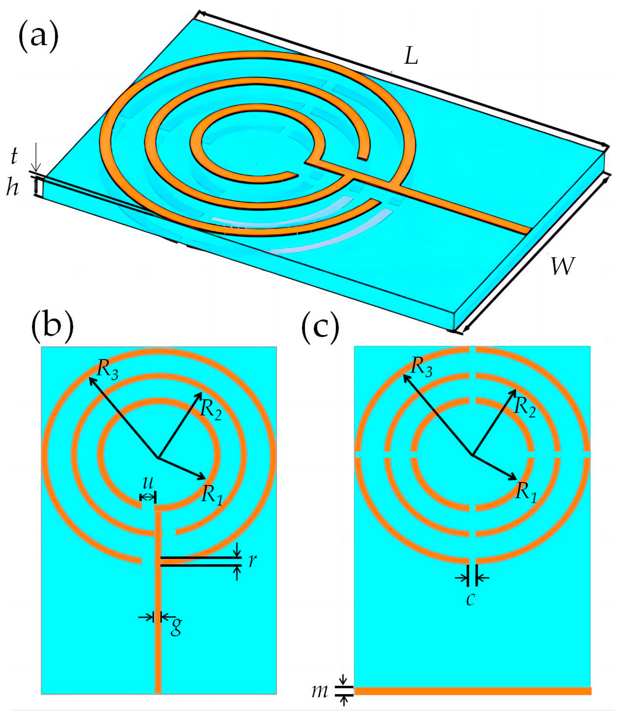
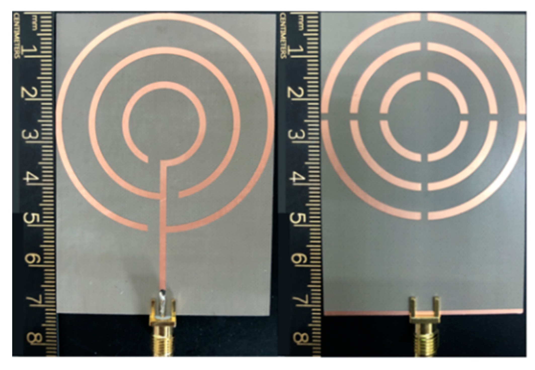
| Parameter | L | W | h | R1 | R2 | R3 | u | r | g | c | m | t |
|---|---|---|---|---|---|---|---|---|---|---|---|---|
| Value/mm | 60 | 42 | 1.6 | 7.5 | 13.5 | 19.5 | 3.17 | 1.5 | 1.5 | 1.5 | 1 | 0.036 |
| Ref | Antenna Size Comparison (L × W mm2) | Resonance Frequency f0 (GHz) | The Number of −10 dB Bandwidth | −10 dB Bandwidth (GHz) | Maximum Gain |
|---|---|---|---|---|---|
| [6] | 20 × 20 | 1.35/2.57/4.57/5.21 | 4 | 1.3–1.39/2.52–2.63/4.49–4.67/5.06–5.18 | - |
| [15] | 26 × 22 | 1.836/3.72/4.32 | 3 | 1.495–2.180/3.35–4.08/4.15–4.49 | 2.43 dBi |
| [20] | 43.6 × 43.6 | 0.829/2.20/1.575/2.450 | 4 | 0.698–0.960/1.710–2.690/1.575/ 2.400–2.500 | 5.3 dBi |
| [22] | 28.05 × 24.90 | 1.226/1.582 | 2 | 1.217–1.235/1.567–1.597 | - |
| [24] | 50 × 50 | 2.4/3.5/4.8 | 3 | 1.88–2.73/3.26–3.79/4.7–5.9 | 4.7 dBi |
| [25] | 100 × 60 | 2.45/3.50/5.31 | 3 | 2.17–2.72/3.34–3.66/4.85–5.77 | 3.89 dBi |
| [27] | 17 × 17 | 1.65/5.90 | 2 | 1.1–2.2/4.8–7.0 | 3 dBi |
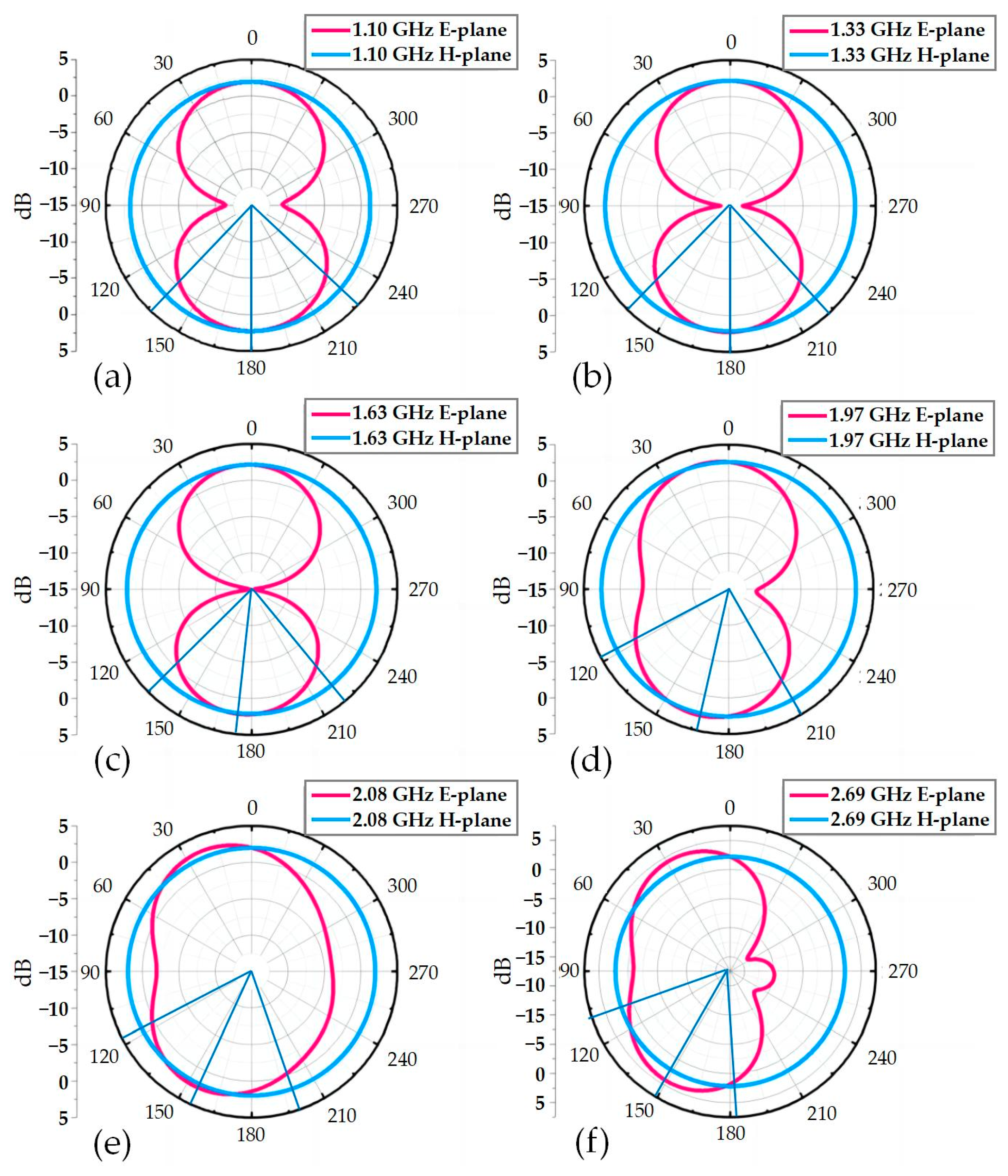
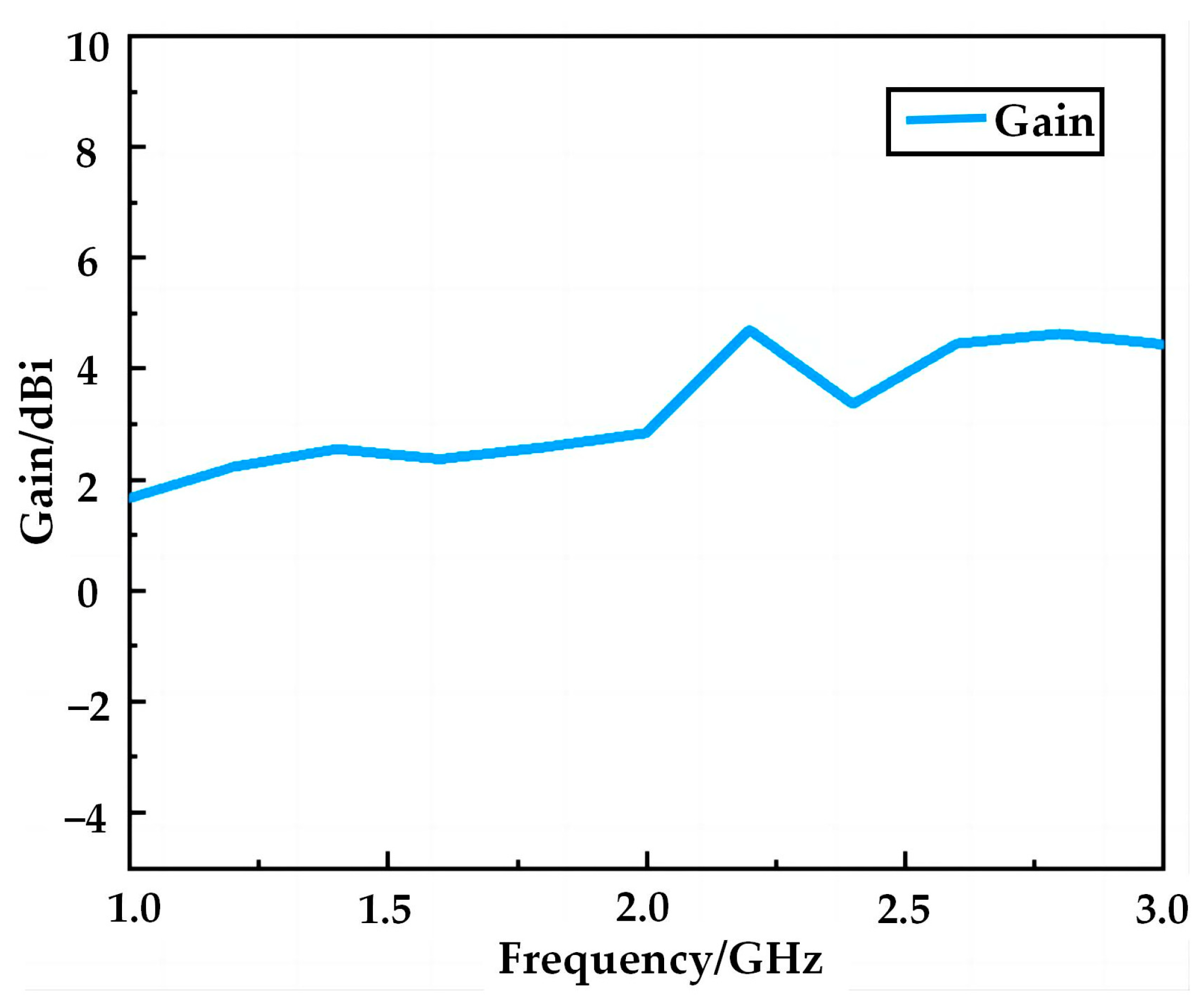
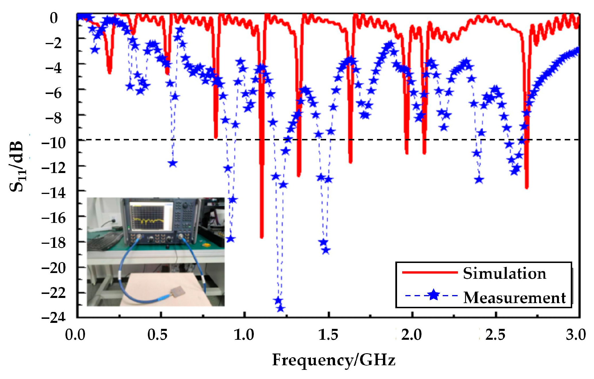
| Proposed | 62 × 42 | 1.10/1.33/1.63/1.97/2.08/2.69 | 6 | 1.097–1.109/1.319–1.329/1.628–1.635/1.964–1.971/2.071–2.078/2.679–2.691 | 4.63 dBi |
Disclaimer/Publisher’s Note: The statements, opinions and data contained in all publications are solely those of the individual author(s) and contributor(s) and not of MDPI and/or the editor(s). MDPI and/or the editor(s) disclaim responsibility for any injury to people or property resulting from any ideas, methods, instructions or products referred to in the content. |
© 2023 by the authors. Licensee MDPI, Basel, Switzerland. This article is an open access article distributed under the terms and conditions of the Creative Commons Attribution (CC BY) license (https://creativecommons.org/licenses/by/4.0/).
Share and Cite
Guo, H.; Chen, Y.; Wu, Q.; Wang, J.; He, Y.; Cao, Y.; Li, M. A Multi-Frequency Omnidirectional Antenna Based on a Ring-Shaped Structure. Micromachines 2023, 14, 994. https://doi.org/10.3390/mi14050994
Guo H, Chen Y, Wu Q, Wang J, He Y, Cao Y, Li M. A Multi-Frequency Omnidirectional Antenna Based on a Ring-Shaped Structure. Micromachines. 2023; 14(5):994. https://doi.org/10.3390/mi14050994
Chicago/Turabian StyleGuo, Honglei, Yu Chen, Qiannan Wu, Jianyang Wang, Yu He, Yonghong Cao, and Mengwei Li. 2023. "A Multi-Frequency Omnidirectional Antenna Based on a Ring-Shaped Structure" Micromachines 14, no. 5: 994. https://doi.org/10.3390/mi14050994