
Lateral Extensional Mode Piezoelectric ZnO-on-Nickel RF MEMS Resonators for Back-End-of-Line Integration
 ,
,
Abstract
:1. Introduction
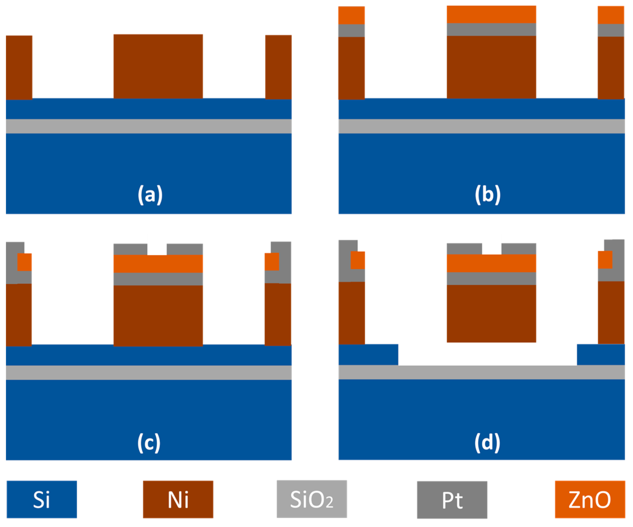
2. Device Structure and Operation
3. Experimental Results
4. Conclusions
Author Contributions
Funding
Data Availability Statement
Conflicts of Interest
References
- Li, C.S.; Li, M.H.; Chen, C.C.; Chin, C.H.; Li, S.S. A Low-Voltage CMOS-Microelectromechanical Systems Thermal-Piezoresistive Resonator with Q > 10,000. IEEE Electron Device Lett. 2015, 36, 192–194. [Google Scholar]
- Kourani, A.; Yang, Y.; Gong, S. L- and X-Band Dual-Frequency Synthesizer Utilizing Lithium Niobate RF-MEMS and Open-Loop Frequency Dividers. IEEE Trans. Ultrason. Ferroelectr. Freq. Control 2021, 68, 1994–2004. [Google Scholar] [CrossRef] [PubMed]
- Naing, T.L.; Rocheleau, T.O.; Ren, Z.; Li, S.-S.; Nguyen, C.T.-C. High-Q UHF Spoke-Supported Ring Resonators. J. Microelectromech. Syst. 2016, 25, 11–29. [Google Scholar] [CrossRef]
- Wang, J.; Nguyen, C.T.C. 1.156-GHz self-aligned vibrating micromechanical disk resonator. IEEE Trans. Ultrason. Ferroelectr. Freq. Control 2004, 51, 1607–1628. [Google Scholar] [CrossRef]
- Zaghloul, U.; Piazza, G. Highly Scalable NEMS Relays With Stress-Tuned Switching Voltage Using Piezoelectric Buckling Actuators. IEEE Trans. Electron Devices 2014, 61, 3520–3528. [Google Scholar] [CrossRef]
- Zou, J.; Liu, J.; Tang, G. Transverse spurious mode compensation for AlN Lamb wave resonators. IEEE Access 2019, 7, 67059–67067. [Google Scholar] [CrossRef]
- Li, M.H.; Chen, W.C.; Li, S.S. Realizing Deep-Submicron Gap Spacing for CMOS-MEMS Resonators. IEEE Sens. J. 2012, 12, 3399–3407. [Google Scholar]
- Zalalutdinov, M.K.; Cross, J.D.; Baldwin, J.W.; Ilic, B.R.; Zhou, W.; Houston, B.H.; Jeevak, M. CMOS-Integrated RF MEMS Resonators. J. Microelectromech. Syst. 2010, 19, 807–815. [Google Scholar] [CrossRef]
- Jung, M.; Min, B. A Widely Tunable Compact Bandpass Filter Based on a Switched Varactor-Tuned Resonator. IEEE Access 2019, 7, 95178–95185. [Google Scholar] [CrossRef]
- Naing, T.L.; Rocheleau, T.O.; Alon, E.; Nguyen, C.T.-C. Low-Power MEMS-Based Pierce Oscillator Using a 61-MHz Capacitive-Gap Disk Resonator. IEEE Trans. Ultrason. Ferroelectr. Freq. Control 2020, 67, 1377–1391. [Google Scholar] [CrossRef]
- Song, Y.H.; Gong, S. Elimination of Spurious Modes in SH0 Lithium Niobate Laterally Vibrating Resonators. IEEE Electron Device Lett. 2015, 36, 1198–1201. [Google Scholar] [CrossRef]
- Jicong, Z.; Zhu, Z.; Sun, H.; Lv, S.; Wang, X.; Song, C. A MEMS Fabrication Process with Thermal-Oxide Releasing Barriers and Polysilicon Sacrificial Layers for AlN Lamb-Wave Resonators to Achieve fs·Qm > 3.42 × 10¹². Micromachines 2021, 12, 892. [Google Scholar]
- Martínez-Cisneros, E.; Velosa, L.A.; Elvira-Hernández, E.A.; Nava-Galindo, O.I.; Aguilera-Cortés, L.A.; Pérez-Cuapio, R.; Leon, A.D.; López-Huerta, F.; Salgado, R. Analytical Modeling of the Mechanical Behavior of MEMS/NEMS-Multilayered Resonators With Variable Cross-Sections for Sensors and Energy Harvesters. IEEE Access 2021, 9, 81040–81056. [Google Scholar] [CrossRef]
- Rao, K.S.; Thalluri, L.N.; Guha, K.; Sravani, K.G. Fabrication and Characterization of Capacitive RF MEMS Perforated Switch. IEEE Access 2018, 6, 77519–77528. [Google Scholar]
- Bukhari, S.A.R.; Saleem, M.M.; Hamza, A.; Bazaz, S.A. A Novel Design of High Resolution MEMS Gyroscope Using Mode-Localization in Weakly Coupled Resonators. IEEE Access 2021, 9, 157597–157608. [Google Scholar] [CrossRef]
- Li, J.; Guo, C.; Mao, L.; Xiang, J.; Huang, G.; Yuan, T. Monolithically 3-D Printed Hemispherical Resonator Waveguide Filters With Improved Out-of-Band Rejections. IEEE Access 2018, 6, 57030–57048. [Google Scholar] [CrossRef]
- Hummel, G.; Hui, Y.; Rinaldi, M. Reconfigurable Piezoelectric MEMS Resonator Using Phase Change Material Programmable Vias. J. Microelectromech. Syst. 2015, 24, 2145–2151. [Google Scholar] [CrossRef]
- Svilicic, B.; Mastropaolo, E.; Flynn, B.; Cheung, R. Electrothermally Actuated and Piezoelectrically Sensed Silicon Carbide Tunable MEMS Resonator. IEEE Electron Device Lett. 2012, 33, 278–280. [Google Scholar] [CrossRef]
- Lavasani, H.M.; Pan, W.; Harrington, B.P.; Abdolvand, R.; Ayazi, F. Electronic Temperature Compensation of Lateral Bulk Acoustic Resonator Reference Oscillators Using Enhanced Series Tuning Technique. IEEE J. Solid-State Circuits 2012, 47, 1381–1393. [Google Scholar] [CrossRef]
- Abdolvand, R.; Lavasani, H.M.; Ho, G.K.; Ayazi, F. Thin-film piezoelectric-on-silicon resonators for high-frequency reference oscillator applications. IEEE Trans. Ultrason. Ferroelectr. Freq. Control 2008, 55, 2596–2606. [Google Scholar] [CrossRef]
- Demirci, M.U.; Nguyen, C.T.C. Mechanically Corner-Coupled Square Microresonator Array for Reduced Series Motional Resistance. J. Microelectromech. Syst. 2006, 15, 1419–1436. [Google Scholar] [CrossRef]
- Wang, J. Self-Aligned Radial Contour Mode Micromechanical Disk Resonators for Wireless Communications. Ph.D. Thesis, University of Michigan, Ann Arbor, MI, USA, 2006. [Google Scholar]
- Jung, I.S.; Ryu, C.; Piazza, G.; Kim, H.J. A Study on the Effects of Bottom Electrode Designs on Aluminum Nitride Contour-Mode Resonators. Micromachines 2019, 10, 758. [Google Scholar] [CrossRef] [PubMed]
- Mortada, O.; Zahr, A.H.; Orlianges, J.-C.; Crunteanu, A.; Chatras, M.; Blondy, P. Analysis and optimization of acoustic wave micro-resonators integrating piezoelectric zinc oxide layers. J. Appl. Phys. 2017, 121, 074504. [Google Scholar] [CrossRef]
- Zaman, A.; Alsolami, A.; Rivera, I.F.; Wang, J. Thin-Piezo on Single-Crystal Silicon Reactive Etched RF MEMS Resonators. IEEE Access 2020, 8, 139266–139273. [Google Scholar] [CrossRef]
- Gryba, T.; Carlier, J.; Wang, S.; Zhao, X.; Guo, S.; Lefebvre, J.-E. ZnO Contour Mode Resonator. In Proceedings of the 10th Congres Français d’Acoustique, Lyon, France, 12–16 April 2010. [Google Scholar]
- Simeoni, P.; Piazza, G. Aluminum Nitride 4-Beam Piezoelectric Nanoscale Ultrasound Transducer (pNUT). J. Microelectromech. Syst. 2021, 30, 814–822. [Google Scholar] [CrossRef]
- Muralt, P.; Conde, J.; Artieda, A.; Martin, F.; Cantoni, M. Piezoelectric materials parameters for piezoelectric thin films in GHz applications. Int. J. Microw. Wirel. Technol. 2009, 1, 19–27. [Google Scholar] [CrossRef]
- Hsu, W.-T.; Lee, S.; Nguyen, C.T.-C. In Situ Localized Annealing for Contamination Resistance and Enhanced Stability in Nickel Micromechanical Resonators. In Proceedings of the Digest of Technical Papers, 10th International Conference on Solid-State Sensors and Actuators, Sendai, Japan, 7–10 June 1999; pp. 932–935. [Google Scholar]
- Alsolami, A.; Zaman, A.; Rivera, I.; Baghelani, M.; Wang, J. Improvement of Deep Reactive Ion Etching Process for Motional Resistance Reduction of Capacitively Transduced Vibrating Resonators. IEEE Sens. Lett. 2018, 2, 5000104. [Google Scholar] [CrossRef]
- Wei, M.; Avila, A.; Rivera, I.; Baghelani, M.; Wang, J. ZnO on nickel RF micromechanical resonators for monolithic wireless communication applications. J. Micromech. Microeng. 2017, 27, 055006. [Google Scholar] [CrossRef]
- Rivera, I.; Avila, A.; Wang, J. Fourth-Order Contour Mode ZnO-on-SOI Disk Resonators for Mass Sensing Applications. Actuators 2016, 4, 60–76. [Google Scholar] [CrossRef]
- Shiari, B.; Najafi, K. Surface Effect Influence on the Quality Factor of Microresonators. In Proceedings of the The 17th International Conference on Solid-State Sensors, Barcelona, Spain, 16–20 June 2013. [Google Scholar]
- Huang, W.-L.; Ren, Z.; Lin, Y.-W.; Chen, H.-Y.; Lahann, J.; Nguyen, C.T.-C. Fully Monolithic CMOS Nickel Micromechanical Resonator Oscillator. In Proceedings of the IEEE 21st International Conference on Micro Electro Mechanical Systems, Tucson, AZ, USA, 13–17 January 2008. [Google Scholar]
- Huang, W.-L.; Ren, Z.; Nguyen, C.T.-C. Nickel Vibrating Micromechanical Disk Resonator with Solid Dielectric Capacitive-Transducer Gap. In Proceedings of the 2006 IEEE International Frequency Control Symposium, Miami, FL, USA, 5–7 June 2006; pp. 839–847. [Google Scholar]
- Chaudhuri, R.R.; Bhattacharyya, T.K. Electroplated nickel based micro-machined disk resonators for high frequency applications. Microsyst. Technol. 2013, 19, 525–535. [Google Scholar] [CrossRef]


| Resonator Device Structure | fr (MHz) | Q | Rm | IL (dB) |
|---|---|---|---|---|
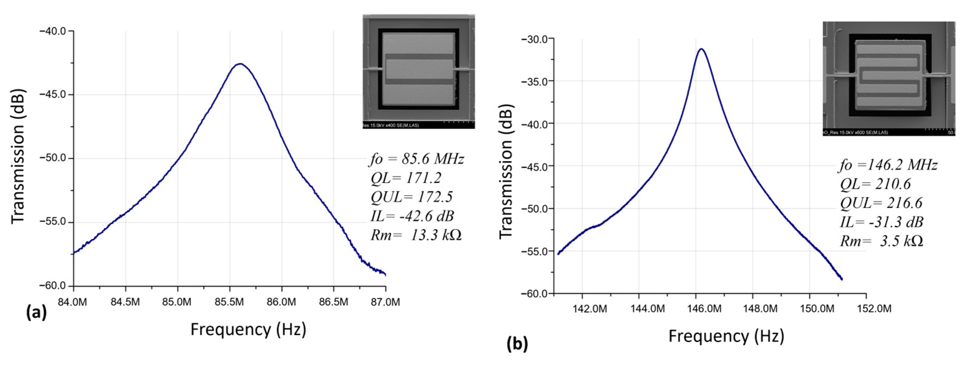
| 82 μm width/length, 3 IDT | 85.6 | 172.5 | 13.3 kΩ | −42.6 |
| 82 μm width/length, 5 IDT | 146.2 | 216.6 | 3.5 kΩ | −31.3 |
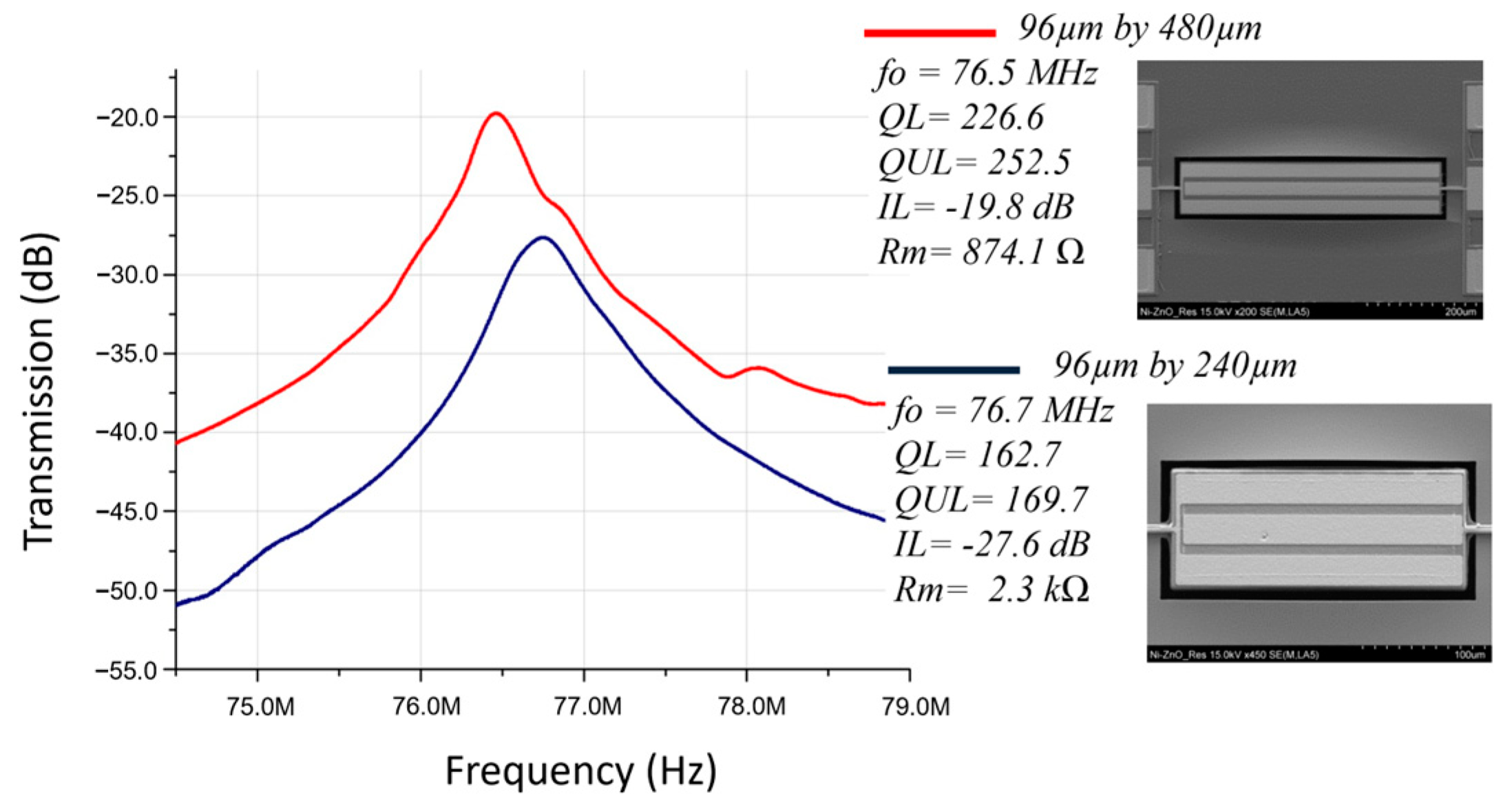
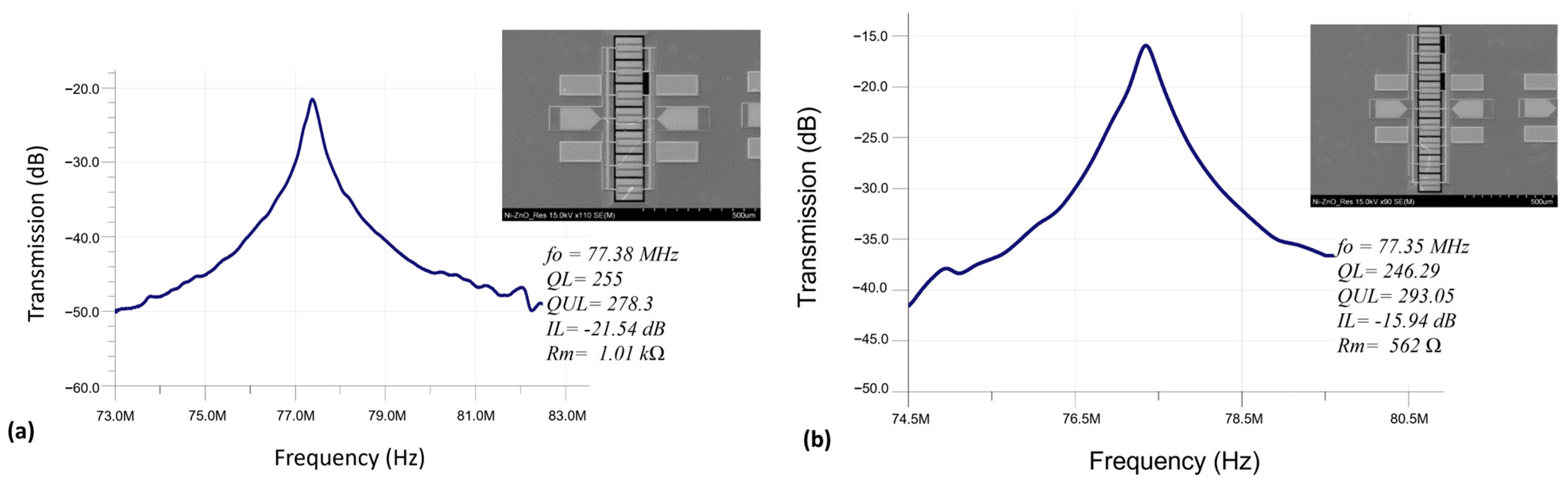
| 96 μm width, 240 μm length | 76.7 | 169.7 | 2.3 kΩ | −27.6 |
| 96 μm width, 480 μm length | 76.5 | 252.5 | 874.1 Ω | −19.8 |
| 1 × 7 coupled resonator array | 77.1 | 186.6 | 1.1 kΩ | −21.85 |
| 1 × 9 coupled resonator array | 77.1 | 183.5 | 623 Ω | −17.2 |
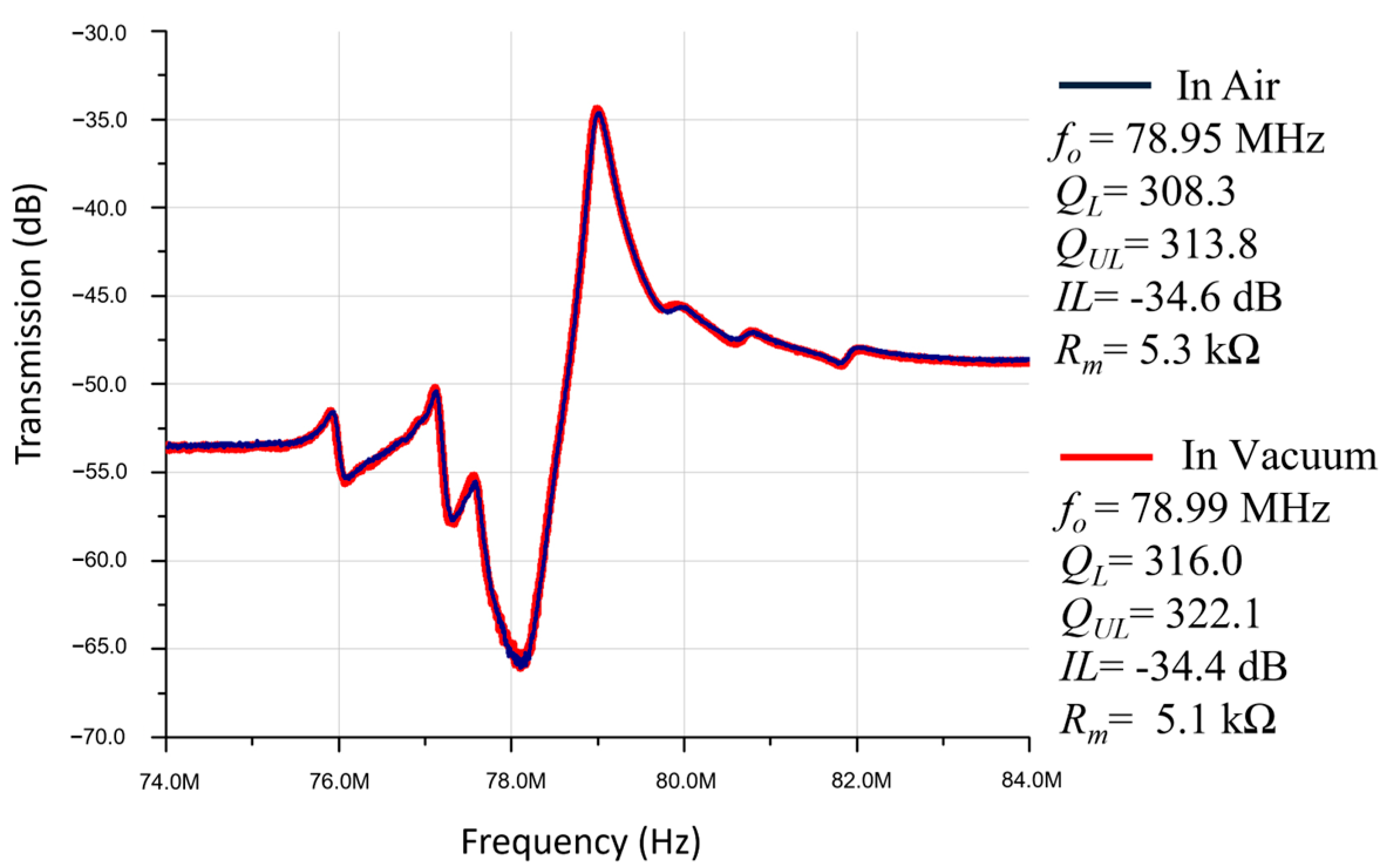
| 96 μm width, 120 μm length resonator tested in air | 78.95 | 313.8 | 5.3 kΩ | −34.6 |
| 96 μm width, 120 μm length resonator tested in vacuum | 78.99 | 322.1 | 5.1 kΩ | −34.4 |
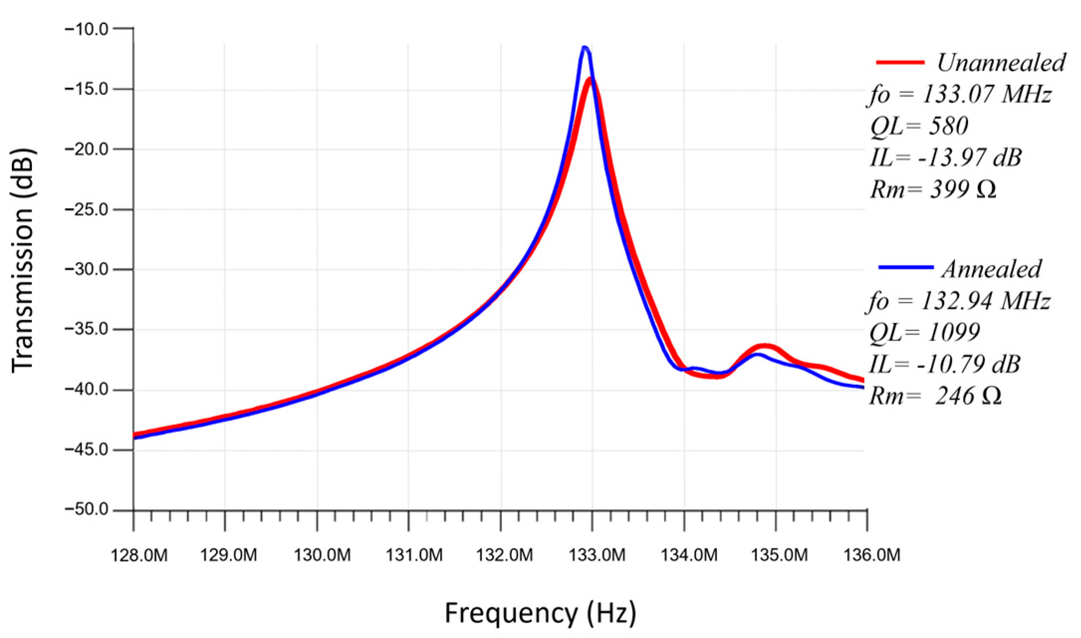
| 60 μm width/length, 5 IDT resonator measured before localized annealing process | 133.07 | 580 | 399 Ω | −13.97 |
| 60 μm width/length, 5 IDT resonator measured after localized annealing process | 132.94 | 1099 | 246 Ω | −10.79 |
| MEMS Designs and Trabsduction Technology | fr (MHz) | Q | Rm | IL (dB) |
|---|---|---|---|---|
| CMOS nickel clamped-clamped beam resonator (capacitively transduced) [35] | 6.62 | 576 | - | −92 |
| Nickel-based centrally anchored disk micro-machined resonators (capacitively transduced) [36] | 15.35 | 66.5 | - | −82 |
| Nickel mechanically coupled flexural-mode disk resonator arrays, 9 disk resonators. (capacitively transduced) [34] | 76.7 | 1092 | 5.8 kΩ | −40 |
| Lateral-extensional mode piezoelectric ZnO-on-Nickel (piezoelectrically transduced) (this work) | 132.94 | 1099 | 246 Ω | −10.76 |
Disclaimer/Publisher’s Note: The statements, opinions and data contained in all publications are solely those of the individual author(s) and contributor(s) and not of MDPI and/or the editor(s). MDPI and/or the editor(s) disclaim responsibility for any injury to people or property resulting from any ideas, methods, instructions or products referred to in the content. |
© 2023 by the authors. Licensee MDPI, Basel, Switzerland. This article is an open access article distributed under the terms and conditions of the Creative Commons Attribution (CC BY) license (https://creativecommons.org/licenses/by/4.0/).
Share and Cite
Zaman, A.; Alsolami, A.; Wei, M.; Rivera, I.; Baghelani, M.; Wang, J. Lateral Extensional Mode Piezoelectric ZnO-on-Nickel RF MEMS Resonators for Back-End-of-Line Integration. Micromachines 2023, 14, 1089. https://doi.org/10.3390/mi14051089
Zaman A, Alsolami A, Wei M, Rivera I, Baghelani M, Wang J. Lateral Extensional Mode Piezoelectric ZnO-on-Nickel RF MEMS Resonators for Back-End-of-Line Integration. Micromachines. 2023; 14(5):1089. https://doi.org/10.3390/mi14051089
Chicago/Turabian StyleZaman, Adnan, Abdulrahman Alsolami, Mian Wei, Ivan Rivera, Masoud Baghelani, and Jing Wang. 2023. "Lateral Extensional Mode Piezoelectric ZnO-on-Nickel RF MEMS Resonators for Back-End-of-Line Integration" Micromachines 14, no. 5: 1089. https://doi.org/10.3390/mi14051089