Communication

On-Chip E00–E20 Mode Converter Based on Multi-Mode Interferometer

1
School of Physics, Changchun University of Science and Technology, Changchun 130022, China
2
State Key Laboratory of Integrated Optoelectronics, College of Electronic Science and Engineering, Jilin University, Changchun 130012, China
*
Author to whom correspondence should be addressed.
Micromachines 2023, 14(5), 1073; https://doi.org/10.3390/mi14051073
Submission received: 20 April 2023 / Revised: 11 May 2023 / Accepted: 17 May 2023 / Published: 18 May 2023

Abstract

:
Mode converters is a key component in mode-division multiplexing (MDM) systems, which plays a key role in signal processing and multi-mode conversion. In this paper, we propose an MMI-based mode converter on 2%-Δ silica PLC platform. The converter transfers E00 mode to E20 mode with high fabrication tolerance and large bandwidth. The experimental results show that the conversion efficiency can exceed −1.741 dB with the wavelength range of 1500 nm to 1600 nm. The measured conversion efficiency of the mode converter can reach −0.614 dB at 1550 nm. Moreover, the degradation of conversion efficiency is less than 0.713 dB under the deviation of multimode waveguide length and phase shifter width at 1550 nm. The proposed broadband mode converter with high fabrication tolerance is promising for on-chip optical network and commercial applications.

1. Introduction

With the development of new generation communication technology and large-capacity signal processing technology, the demand for high-speed data transmission and large-capacity data processing is increasing. Various multiplexing methods have been proposed for this purpose, such as wavelength division multiplexing (WDM), space division multiplexing (SDM) and polarization division multiplexing (PDM) technologies [1,2,3,4,5,6,7,8]. Mode division multiplexing (MDM) has been considered as a promising technology [9,10] that can significantly improve the capacity of optical communication, on-chip interconnect, and computation [11,12]. Since the orthogonal eigenmodes of the same wavelength propagate in a single channel without inter-channel crosstalk, cooperation with WDM technology, MDM technology increases overall transmission capacity dramatically [13,14]. In MDM system, mode converter with broad bandwidth, low insertion loss, and high mode conversion efficiency is the key components between fundamental mode and higher-order modes at optical nodes [15,16,17,18,19,20]. Mode converters have been demonstrated on different structures, such as asymmetrical directional couplers (ADCs) [21], Y-branch [22], multimode interferometers (MMIs) [23,24]. Although ADCs convertors show low loss and high fabrication tolerant, they suffer from high wavelength dependence. Y-branch converters contribute high crosstalk between modes. Nowadays, slotted waveguide and etched metasurface waveguide converter show ultra-compact footprint and high efficiency of mode conversion [17,25,26,27,28]. However, for commercial usage, large fabrication tolerances, in the micrometer range, are necessary. Compared with other kinds of mode conversion techniques, the mode converters based on MMIs shows broad bandwidth and large fabrication tolerance.
In this paper, we demonstrate an MMI-based mode converter on silica based planar lightwave circuits (PLC) platform with 2% refractive index difference(Δ). The light of E00 mode will be converted into E20 after propagating through the device. We optimize the mode converter through beam propagation method (BPM). The simulation result shows a conversion efficiency of −0.083 dB at 1550 nm. After fabrication, the converter shows high mode conversion efficiency of −0.614 dB at 1550 nm. From 1500 nm to 1600 nm, the conversion efficiency exceeds −1.741 dB. Moreover, the degradation of conversion efficiency is less than 0.713 dB under the deviation of multimode waveguide length and phase shifter width at 1550 nm. Compared with other mode conversion techniques, our designed MMI-based mode converter reduces the device size while ensuring high conversion efficiency, which has the advantages of broad bandwidth and large fabrication tolerance. The mode converter is suitable for large scale and complex on-chip optical networks. The high fabrication tolerance contributes the devices are promising for commercial application.

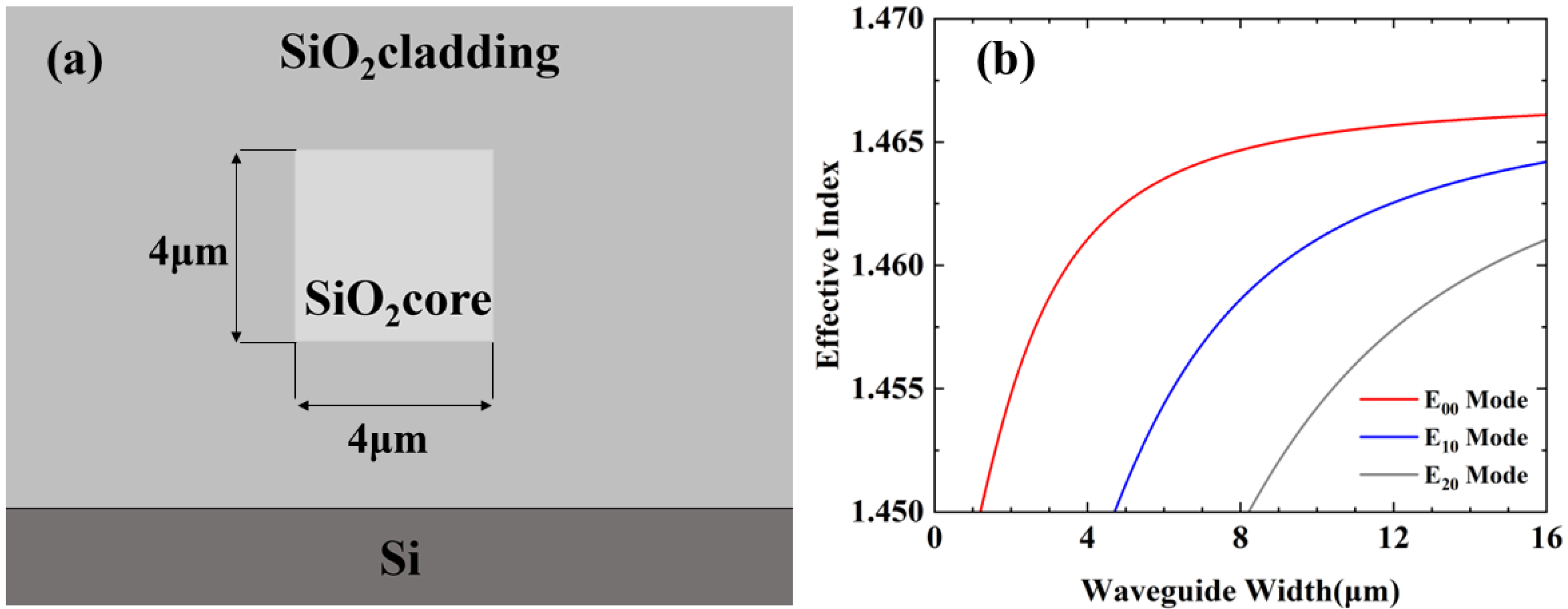
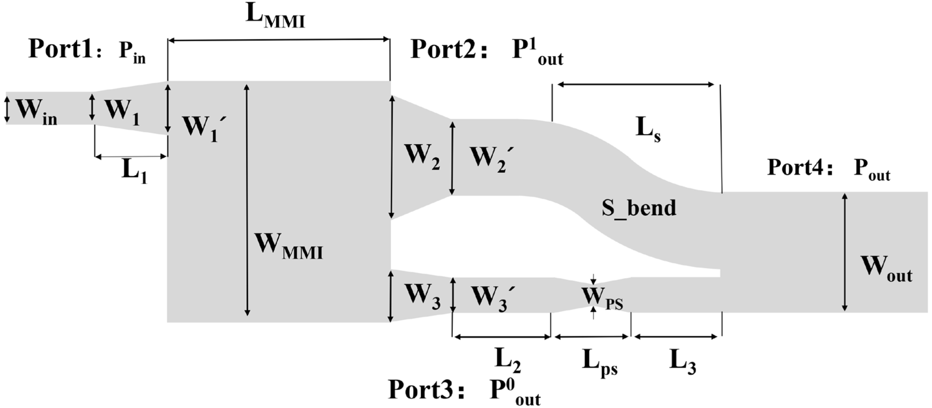
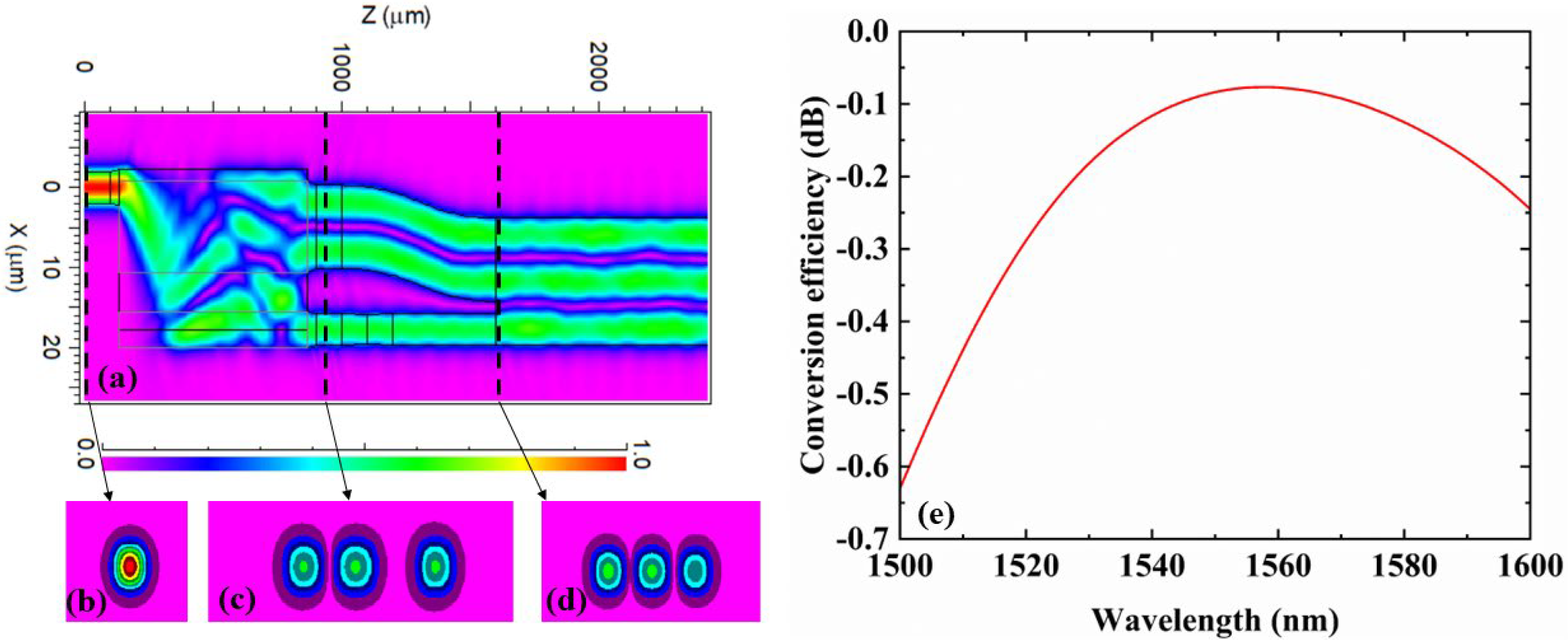
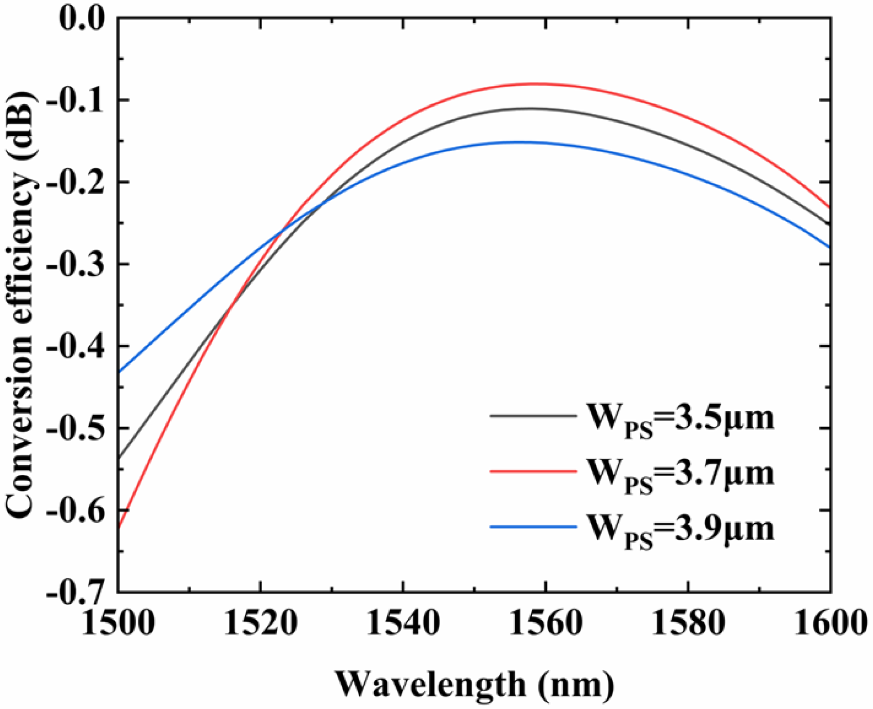
2. Design and Simulation

Several material platforms have been investigated for integrated photonics circuits, including silicon-on-insulator (SOI), silicon nitride (SiN), polymer-based PLC and silica-based PLC. SOI and SiN waveguide devices are compact and promising for co-package optics. However, they suffer from low fabrication tolerant and high coupling loss with fiber. Polymer based PLC devices are attractive for thermo-optical switch and high-speed modulators. The stability of polymers is a major limitation to their commercial usage. Compared with other platforms, the silica-based PLC have advantages of low loss, good match of the optical mode field with an optical fiber, and is commercially available. However, the low thermal optical coefficient (TOC) of silica contributes to high power consumption when thermo-optical tuning is used. Therefore, the silica-based PLC platform is suitable for our passive converter.
Figure 1a shows the cross section of single mode waveguide. The thickness is 4 μm. With different germanium oxide doping, the refractive index difference between claddings and cores is 2%. Refractive indices are 1.473 and 1.444 at 1550 nm, respectively. According to the calculated relationship between effective refractive indices and waveguide width shown in Figure 1b, we choose 4 µm as the height and width to maintain single mode propagation.
The schematic of the proposed MMI-based mode converter is demonstrated in Figure 2. The converter is constructed by input waveguide, tapered waveguide, 66% mode converter MMI, phase shifter waveguide, S-bend, and output waveguide. The fundamental mode is coupled into Port 1 ( P in ) through a tapered waveguide. The 66% E00 mode is converted into E10 at Port 2 ( P o u t 1 ) after the first MMI. The light left propagates in fundamental mode through Port 3 ( P o u t 0 ). A phase shifter is introduced to ensure π phase difference between E00 mode and E10 mode. When these lights meet at the second MMI, the mode of light is converted to E20 mode at Port 4 ( P out ).
The first MMI coupler is a 3 × 3 MMI with outputs modified into two, one of which is for first-order mode output, another is for fundamental mode output. The length of the conventional 3 × 3 MMI is equal to the length of the 66% mode converter MMI, which is L M M I = L 3 1 = 3 L c / 3 = L c , with L c as the coupling length based on self-imaging property and it is given by [29]:
L c = π β 0 β 1 = 4 n r W 2 3 λ 0
where β 0 is the fundamental mode propagation constant, β 1 the first-order mode propagation constant, λ 0 is the operation wavelength, n r is the refractive index of the core waveguide and W is the effective width taking into account the Goos–Hänchen shifts at the ridge boundaries, whose displacement is very small, and can approximatively equal to the width of MMI ( W M M I ). For a conventional 3 × 3 MMI, when E00 mode is input from port P i n , the powers at three output ports of E00 modes are equal. However, the phases of the three outputs are φ 11 = φ 0 + 5 π / 3 , φ 12 = φ 0 + 2 π / 3 and φ 13 = φ 0 + π , respectively, where φ 0 is a constant phase. Therefore, the phase difference between the two fundamental modes at Port 2 is π. We combine these two fundamental modes to form E10 mode. As for of the E20 mode, we need a 2/3π phase shifter. With BPM calculating, the width and length of the phase shifter are W P S = 3.7   μ m and L P S = 200   μ m , respectively.
Based on the above principle, we use BPM for the design and optimization of the device at 1550 nm. To reduce the loss caused by mode mismatch, tapered waveguides are introduced between MMI region and waveguides. Widths of tapers are transferred from W 1 = 4   μ m , W 2 = 11.5   μ m and W 3 = 4.5   μ m to W 1 = 4.5   μ m , W 2 = 10.4   μ m , and W 3 = 4   μ m , linearly. The gap between E10 mode port and E00 mode port is 4.85 µm. The length of these three tapered waveguides is 35 µm. There are 100-µm-length straight waveguides after E00 and E10 mode port. We use S-bend to connect Port 2 with output width. The arc radius of the S-bend is above 2 cm. The loss caused by S-bend could be neglected. The length of the straight waveguide that connects phase shifter and output waveguide is chosen to be 400 µm. The width of the output waveguide is set to be 15.9 µm. In our design, the width of the MMI (WMMI) is designed to be 22.25 µm, which is used to avoid coupling between E10 mode and E00 mode at ports 2 and 3. Therefore, the calculated MMI coupler length is optimized to be LMMI = 730 μm. The length of the output waveguide is 800 µm. The total length of the mode converter is 2400 µm.
Figure 3a shows the field distribution of the device at 1550 nm wavelength with fundamental mode is input. Figure 3b shows the fundamental mode field distribution of the input. The mode distributions of E10 at port 2 and E00 at port 3 of the mode converter MMI are shown in Figure 3c. Figure 3d shows the mode distribution of E20. From Figure 3a, the E00 mode is successfully converted to the E20 mode. In the simulation, we set the E00 mode input power of port1 to 1 and simulated the conversion efficiency of the mode converter from 1500 nm to 1600 nm, as shown in Figure 3e. The conversion efficiency in percent (Ep) and dB (Ed) are calculated by Equations (2) and (3), respectively. Here, b is the propagation loss of the E00 mode in the dB scale [30].
E p = ( 1 10 0.1 b ) × 100 %
E d = 10 lg ( 1 10 0.1 b )
At 1550 nm wavelength, the conversion efficiency is 96.2% (−0.083 dB). From 1500 nm to 1600 nm, simulation results show that the conversion efficiency exceeds −0.630 dB. In summary, we obtain a mode conversion from E00 to E20 at 1550 nm with a conversion efficiency of −0.083 dB.

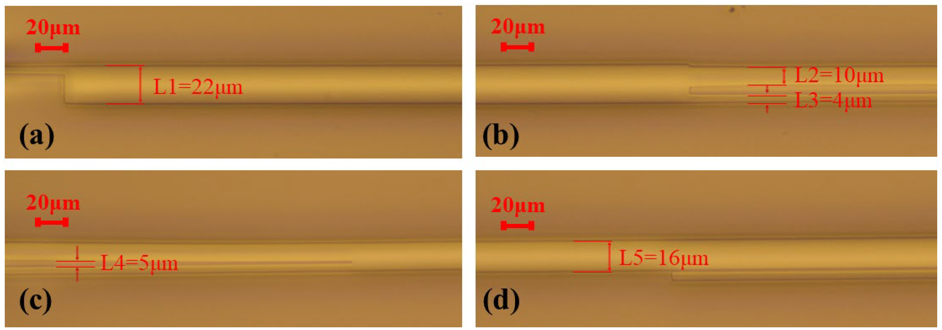
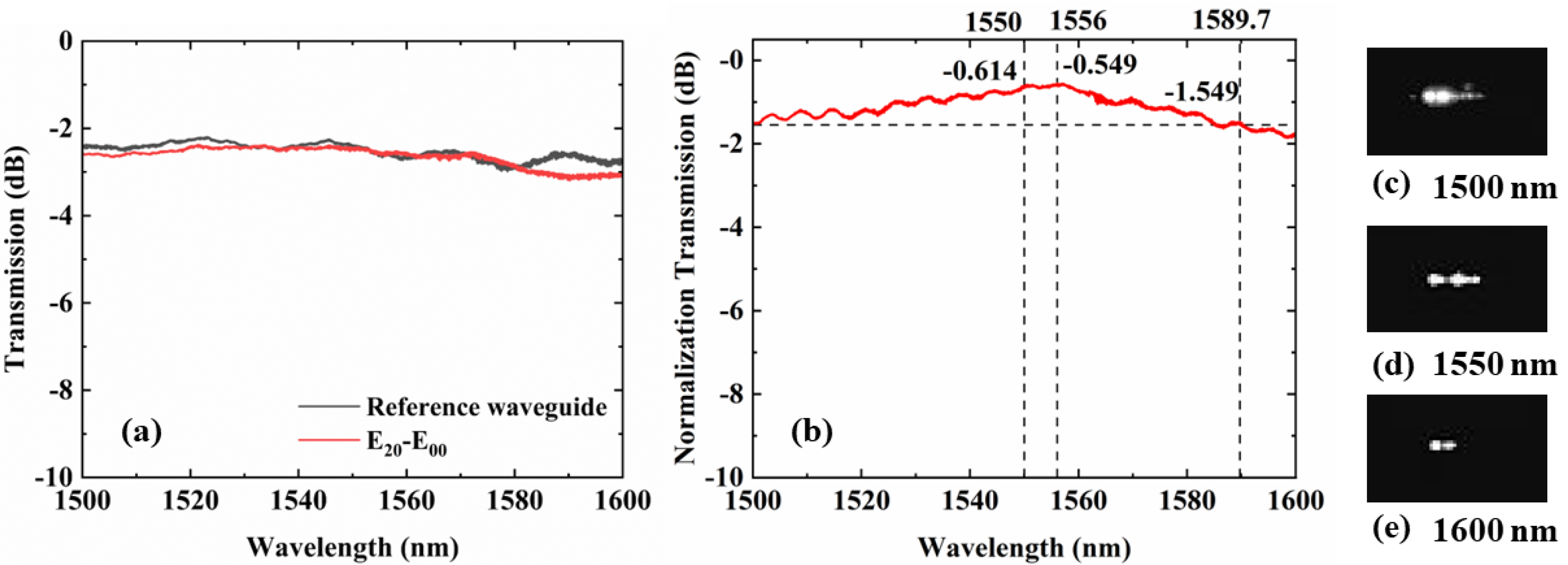
3. Characterization and Discussion

The proposed mode converter was fabricated by the PLC foundry, SHIJIA, China. First, the bottom cladding of ~15 µm was thermally oxidized on silicon substrate. Second, we grew a 4-µm-thickness silica core layer above the bottom cladding by plasma enhanced chemical vapor deposition (PECVD). The waveguide was formed by etching through inductively coupled plasma etching (ICP) technique. Finally, PECVD was again used to deposit the upper cladding. Since the existing coupling test system is difficult to directly monitor the high-order mode power, a mode demultiplexer was introduced at the end of the output waveguide to convert the E20 mode to the E00 mode to indirectly characterize the higher-order mode power. The mode multiplexer/demultiplexer of E20 mode and a reference waveguide are fabricated simultaneously. The microscope images of the demonstrated converter are shown in Figure 4a–d.
In Figure 4a, the measured width of the MMI is 22 μm. The widths of the two output ports are measured in Figure 4b at 10 μm and 4 μm, respectively. The S bend is separated from the phase shifter by a large distance of 5 μm, which can be observed in Figure 4c. The width of the output waveguide is measured to be 16 μm in Figure 4d.
The E00 mode is coupled into the device by edge coupling system. The spectra of the reference straight waveguide and the mode multiplexed/demultiplexer for the E20 mode are shown in Figure 5a. The normalized spectral response of the E00 to E20 mode converter experimental measure data is shown in Figure 5b. The experimental results show that the conversion efficiency can exceed −1.741 dB with the wavelength range of 1500 nm to 1600 nm. The conversion efficiency of the device is −0.614 dB (87%) at 1550 nm. The maximum conversion efficiency is −0.549 dB (88%) at 1556 nm. The 1-dB bandwidth of the device is 90 nm. The captured output mode patterns at different wavelengths shown in Figure 5c–e.
We fabricate proposed device with different lengths of MMI and widths of phase shifter to perform fabrication tolerant. The key components, MMIs and phase shifters, influence the conversion efficiency of the device a lot. We study the fabrication tolerance by changing length and width of MMI and phase shifter, and observe the output power of E20. The deviations are 0 and ±10 µm for LMMI and 0 and ±0.2 µm for WPS. The simulation result is shown in the Figure 6. We can see that when LMMI move away from their optimal values, the conversion efficiency of E00–E20 has different degrees of degradation at wavelength 1550 nm., which means that the change of LMMI will cause an impact on the conversion efficiency of the device. At 1550 nm, the conversion efficiency varies from −0.083 dB to −0.234 dB.
Similarly, the influence of WPS on the conversion efficiency of the device is simulated. Figure 7 shows the dependence of the E00–E20 conversion efficiency on the WPS. We use the optimal value LMMI = 730 μm as the length of MMI. It can be seen that the change of WPS does have a certain impact on the conversion efficiency of the mode converter. At the wavelength of 1550 nm, the conversion efficiency of the mode converter varies from −0.083 dB to −0.155 dB. Compared with LMMI, the device is more sensitive to WPS.
We summary the spectra of all samples and separate in four groups, as shown in Figure 8a–d. It can be seen that at the wavelength of 1550 nm, the conversion efficiency degradation of the device is less than 0.713 dB when changing LMMI and WPS. However, the conversion efficiency of the converter proposed is lower than others. So there are still some cases that need to be discussed for the MMI-based mode converter we designed. First of all, during the simulation, we initially expected the conversion efficiency to be −0.083 dB (97%) at 1550 nm. However, the actual test results show that the conversion efficiency of the mode converter can only reach −0.614 dB (87%) at 1550 nm. The reason is the differences in geometry and refractive index of cores with respect to design parameters. The device has good repeatability, parameter scanning will help but only if you also have good repeatability. This problem is solved by parameter scanning while fabrication. Secondly, in Figure 8a,d, we note that when LMMI = 720 μm the normalized transmission may exceed 0, which is caused by the normalization procedure owing to the vibration of the reference waveguide.

4. Discussion

In order to clearly demonstrate the mode converter, Table 1 illustrates the performance comparisons between the reported E00–E20 mode converters. The compact silicon-on-insulator based device using a 1 × 4 Y-junction and 4 × 4 MMI couplers can realize 16 different input-output mode conversions in C-band [31]. The mode converter with a cascaded tapers structure exhibits balanced performances [32]. The mode converter designed in Ref. [33] with phase change material inlaid in multimode waveguide has a large bandwidth and high conversion efficiency. However, the mode converters in these reports only have simulation results and are not actually fabricated. Owing to the low fabrication tolerance of the SOI platform, the device is hard to fabricate with the designed characteristics. Moreover, the SOI device is fixed after fabrication. To obtain a flexible and reconfigurable device, mode switching is necessary for the MDM system. The mode switch based on phase change materials or van der Waals materials can be used to achieve low power consumption and higher-order reconfigurable mode conversion [33,34,35]. In ref. [36], a mode converter based on cascaded long-period waveguide grating is mentioned, which uses the UV-curable polymer material EPO as the design material. The conversion efficiency of the device can be estimated to be more than 90% at 1550 nm. The polymer-based PLC is a low-cost platform. The design method could be verified on polymer. The design method is also inspiring for silica-based PLC. After comparison, the device proposed shows high conversion efficiency, high tolerance and large bandwidth, which has a good application prospect in MDM system.

5. Conclusions

In this work, we proposed an MMI-based mode converter that has the capability to efficiently convert E00 mode to E20 mode. The experimental results show that the fabricated device has high tolerance and high conversion efficiency, and the efficiency of the fabricated mode converter is −0.614 dB at 1550 nm wavelength. The degradation of conversion efficiency is less than 0.713 dB within the range of fabricate deviation. This paper provides a solution for efficient conversion in MDM systems.

Author Contributions

Conceptualization, Y.Z., Y.Y., D.Z.; methodology, Y.Z., Y.D., D.Z. and Y.L.; investigation, Y.Z., Y.D. and S.Z.; writing-original draft preparation, Y.Z., Y.Y. and Y.D.; writing—review and editing, all authors; supervision, D.Z., X.S. and Y.L.; project administration, D.Z., X.S. and Y.L. All authors have read and agreed to the published version of the manuscript.

Funding

This work is supported by the National Key Research and Development (R&D) Program of China, NO. 2021YFB2800202.

Data Availability Statement

Not applicable.

Conflicts of Interest

The authors declare no conflict of interest.

References

  1. Winter, M.; Setti, D.; Petermann, K. Cross-Polarization Modulation in Polarization-Division Multiplex Transmission. IEEE Photonics Technol. Lett. 2010, 22, 538–540. [Google Scholar] [CrossRef]
  2. Chun, H.; Rajbhandari, S.; Faulkner, G.; Tsonev, D.; Xie, E.; McKendry, J.J.D.; Gu, E.; Dawson, M.D.; O’Brien, D.C.; Haas, H. LED Based Wavelength Division Multiplexed 10 Gb/s Visible Light Communications. J. Light. Technol. 2016, 34, 3047–3052. [Google Scholar] [CrossRef]
  3. Mizuno, T.; Takara, H.; Sano, A.; Miyamoto, Y. Dense Space-Division Multiplexed Transmission Systems Using Multi-Core and Multi-Mode Fiber. J. Light. Technol. 2016, 34, 582–592. [Google Scholar] [CrossRef]
  4. Goossens, J.W.; Yousefi, M.I.; Jaouen, Y.; Hafermann, H. Polarization-division multiplexing based on the nonlinear Fourier transform. Opt. Express 2017, 25, 26437–26452. [Google Scholar] [CrossRef]
  5. Zhang, Y.; Pan, S. Photonics-based multi-function analog signal processor based on a polarization division multiplexing Mach-Zehnder modulator. Opt. Lett. 2017, 42, 5034–5037. [Google Scholar] [CrossRef]
  6. Gao, Y.; Xu, Y.; Ji, L.; Sun, X.; Wang, F.; Wang, X.; Wu, Y.; Zhang, D. Scalable compact mode (de)multiplexer based on asymmetric Y-junctions. Opt. Commun. 2019, 438, 34–38. [Google Scholar] [CrossRef]
  7. Han, X.; Xiao, H.; Liu, Z.; Zhao, T.; Jia, H.; Yang, J.; Eggleton, B.J.; Tian, Y. Reconfigurable On-Chip Mode Exchange for Mode-Division Multiplexing Optical Networks. J. Light. Technol. 2019, 37, 1008–1013. [Google Scholar] [CrossRef]
  8. Yang, Y.; Liu, J.; Cheng, R.; Jia, J.; Gao, Y.; Shen, L.; Chen, Z.; He, Y.; Li, J. SDM-WDM ROADM Based on Direct-Laser-Writing SDM Core Separator. IEEE Photonics J. 2022, 14, 7230506. [Google Scholar] [CrossRef]
  9. Memon, A.K.; Chen, K.X. Recent advances in mode converters for a mode division multiplex transmission system. Opto-Electron. Rev. 2023, 29, 13–32. [Google Scholar] [CrossRef]
  10. Sun, S.; Che, Y.; Zhu, M.; Lian, T.; Sun, X.; Wang, X.; Huang, Q.; Zhang, D. Mode-insensitive 3-dB power splitter based on multimode-interference coupler. Opt. Laser Technol. 2023, 159, 109017. [Google Scholar] [CrossRef]
  11. Ye, M.; Yu, Y.; Sun, C.; Zhang, X. On-chip data exchange for mode division multiplexed signals. Opt. Express 2016, 24, 528–535. [Google Scholar] [CrossRef]
  12. Gao, Y.; Zhang, D.; Xu, Y.; Fan, X.; Wang, F.; Sun, X. Ultra-broadband polymer E00/E10 mode converter. Opt. Commun. 2022, 508, 127715. [Google Scholar] [CrossRef]
  13. Yu, Y.; Ye, M.; Fu, S. On-Chip Polarization Controlled Mode Converter with Capability of WDM Operation. IEEE Photonics Technol. Lett. 2015, 27, 1957–1960. [Google Scholar] [CrossRef]
  14. Luo, L.W.; Ophir, N.; Chen, C.P.; Gabrielli, L.H.; Poitras, C.B.; Bergmen, K.; Lipson, M. WDM-compatible mode-division multiplexing on a silicon chip. Nat. Commun. 2014, 5, 3069. [Google Scholar] [CrossRef]
  15. Frandsen, L.H.; Elesin, Y.; Frellsen, L.F.; Mitrovic, M.; Ding, Y.; Sigmund, O.; Yvind, K. Topology optimized mode conversion in a photonic crystal waveguide fabricated in silicon-on-insulator material. Opt. Express 2014, 22, 8525–8532. [Google Scholar] [CrossRef]
  16. Deng, Q.; Yan, Q.; Liu, L.; Li, X.; Michel, J.; Zhou, Z. Robust polarization-insensitive strip-slot waveguide mode converter based on symmetric multimode interference. Opt. Express 2016, 24, 7347–7355. [Google Scholar] [CrossRef]
  17. Ye, W.; Yuan, X.; Gao, Y.; Liu, J. Design of broadband silicon-waveguide mode-order converter and polarization rotator with small footprints. Opt. Express 2017, 25, 33176–33183. [Google Scholar] [CrossRef]
  18. Wang, H.; Zhang, Y.; He, Y.; Zhu, Q.; Sun, L.; Su, Y. Compact Silicon Waveguide Mode Converter Employing Dielectric Metasurface Structure. Adv. Opt. Mater. 2018, 7, 1801191. [Google Scholar] [CrossRef]
  19. Chen, R.; Bai, B.; Yang, F.; Zhou, Z. Ultra-compact hybrid plasmonic mode convertor based on unidirectional eigenmode expansion. Opt. Lett. 2020, 45, 803–806. [Google Scholar] [CrossRef]
  20. Wang, T.; Guo, H.; Chen, H.; Yang, J.; Jia, H. Ultra-compact reflective mode converter based on a silicon subwavelength structure. Appl. Opt. 2020, 59, 2754–2758. [Google Scholar] [CrossRef]
  21. Sun, Y.; Xiong, Y.; Ye, W.N. Experimental demonstration of a two-mode (de)multiplexer based on a taper-etched directional coupler. Opt. Lett. 2016, 41, 3743–3746. [Google Scholar] [CrossRef] [PubMed]
  22. Driscoll, J.B.; Grote, R.R.; Souhan, B.; Dadap, J.I.; Lu, M.; Osgood, R.M. Asymmetric Y junctions in silicon waveguides for on-chip mode-division multiplexing. Opt. Lett. 2013, 38, 1854–1856. [Google Scholar] [CrossRef] [PubMed]
  23. Gao, Y.; Sun, X.; Li, P.; Zhang, D. Polymer Mode Selecting Switch Based on Cascaded MMI Couplers. IEEE Photonics Technol. Lett. 2021, 33, 147–150. [Google Scholar] [CrossRef]
  24. Ou, X.; Yang, Y.; Tang, B.; Li, D.; Sun, F.; Zhang, P.; Liu, R.; Li, B.; Li, Z. Low-loss silicon nitride strip-slot mode converter based on MMI. Opt. Express 2021, 29, 19049–19057. [Google Scholar] [CrossRef]
  25. Li, Z.; Kim, M.H.; Wang, C.; Han, Z.; Shrestha, S.; Overvig, A.C.; Lu, M.; Stein, A.; Agarwal, A.M.; Loncar, M.; et al. Controlling propagation and coupling of waveguide modes using phase-gradient metasurfaces. Nat. Nanotechnol. 2017, 12, 675–683. [Google Scholar] [CrossRef]
  26. Meng, Y.; Liu, Z.; Xie, Z.; Wang, R.; Qi, T.; Hu, F.; Kim, H.; Xiao, Q.; Fu, X.; Wu, Q.; et al. Versatile on-chip light coupling and (de)multiplexing from arbitrary polarizations to controlled waveguide modes using an integrated dielectric metasurface. Photonics Res. 2020, 8, 564–576. [Google Scholar] [CrossRef]
  27. Zhao, Y.; Guo, X.; Zhang, Y.; Xiang, J.; Wang, K.; Wang, H.; Su, Y. Ultra-compact silicon mode-order converters based on dielectric slots. Opt. Lett. 2020, 45, 3797–3800. [Google Scholar] [CrossRef]
  28. Meng, Y.; Chen, Y.; Lu, L.; Ding, Y.; Cusano, A.; Fan, J.A.; Hu, Q.; Wang, K.; Xie, Z.; Liu, Z.; et al. Optical meta-waveguides for integrated photonics and beyond. Light Sci. Appl. 2021, 10, 235. [Google Scholar] [CrossRef]
  29. Jifang, Q.; Daolin, Z.; Ye, T.; Jian, W.; Yan, L.; Yue, W. Performance Analysis of a Broadband Second-Order Mode Converter Based on Multimode Interference Coupler and Phase shifter. IEEE Photonics J. 2015, 7, 1–8. [Google Scholar] [CrossRef]
  30. Xu, Y.; Gao, Y.; Liu, S.; Liu, T.; Sun, X.; Tang, B.; Zhang, P.; Zhang, D. Wideband E00-E10 Silicon Mode Converter Based on 180 nm CMOS Technology. Appl. Sci. 2022, 12, 10688. [Google Scholar] [CrossRef]
  31. Linh, H.D.T.; Dung, T.C.; Tanizawa, K.; Thang, D.D.; Hung, N.T. Arbitrary TE0/TE1/TE2/TE3 Mode Converter Using 1 × 4 Y-Junction and 4 × 4 MMI Couplers. IEEE J. Sel. Top. Quantum Electron. 2020, 26, 1–8. [Google Scholar] [CrossRef]
  32. Chen, Z.; Lin, T.; Liu, X.; Lv, H. Ultra-Compact Broadband In-Line Mode Converter Based on a Width-Modulated Silicon Waveguide. IEEE Photonics J. 2021, 13, 1–7. [Google Scholar] [CrossRef]
  33. Fei, Y.; Xu, Y.; Huang, D.; Dong, Y.; Zhang, B.; Ni, Y.; Wai, P.K.A. On-Chip Reconfigurable and Ultracompact Silicon Waveguide Mode Converters Based on Nonvolatile Optical Phase Change Materials. Nanomaterials 2022, 12, 4225. [Google Scholar] [CrossRef]
  34. Wuttig, M.; Bhaskaran, H.; Taubner, T. Phase-change materials for non-volatile photonic applications. Nat. Photonics 2017, 11, 465–476. [Google Scholar] [CrossRef]
  35. Meng, Y.; Feng, J.; Han, S.; Xu, Z.; Mao, W.; Zhang, T.; Kim, J.S.; Roh, I.; Zhao, Y.; Kim, D.-H.; et al. Photonic van der Waals integration from 2D materials to 3D nanomembranes. Nat. Rev. Mater. 2023. [CrossRef]
  36. Jin, W.; Chiang, K.S. Mode converters based on cascaded long-period waveguide gratings. Opt. Lett. 2016, 41, 3130–3133. [Google Scholar] [CrossRef]
Figure 1. (a) Cross section of the silica waveguide. (b) Calculated effective indices of 4-μm-thickness silica waveguide with different widths.
Micromachines 14 01073 g001
Figure 2. Schematic of the MMI-based mode converter.
Micromachines 14 01073 g002
Figure 3. (a) Simulated optical field propagation distribution of the device at 1550 nm. (b) Mode profile of E00 at port 1. (c) Mode profile of E10 at port 2 and E00 at port3. (d) Mode profile of E20 at port 4. (e) Simulated conversion efficiency of the mode converter at 1500 nm to 1600 nm.
Micromachines 14 01073 g003
Figure 4. (ad) Microscopic images of the fabricated mode converter.
Micromachines 14 01073 g004
Figure 5. (a) Measured power loss of the reference waveguide with the E20 mode (de) multiplexer. (b) Conversion efficiency of the mode converter from E00 to E20 in the wavelength range from 1500 nm to 1600 nm. Output mode taken from output port at (c) 1500 nm, (d) 1550 nm and (e) 1600 nm.
Micromachines 14 01073 g005
Figure 6. Simulated conversion efficiency of the mode converter when changing the LMMI from 1500 nm to 1600 nm.
Micromachines 14 01073 g006
Figure 7. Simulated conversion efficiency of the mode converter when changing the WPS from 1500 nm to 1600 nm.
Micromachines 14 01073 g007
Figure 8. (ac) The effect of W P S on the conversion efficiency of the mode converter at a given fabrication error range for wavelengths ranging from 1550 nm to 1600 nm with LMMI of 720 µm, 730 µm and 740 µm, respectively. (d) The effect of LMMI on the conversion efficiency of the mode converter at a given fabrication error range for wavelengths ranging from 1550 nm to 1600 nm when W P S is fixed to 3.7 µm.
Micromachines 14 01073 g008
Table 1. Comparison the designed E00–E20 mode converter with reported works.
Refs.S/EBW (nm)CE (%)StructureMaterialsFootprint (µm2)
[29]E3593MMI+ phase shifterSOI1230 × 8
[31]S3598Y-junction + MMISOI288 × 6.8
[32]S10093Cascaded tapersSOI2.5 × 6.5
[33]S24599PCM inlaid in multimode waveguideSOI2.3 × 1.82
[34]EAt 1550 nm90Long-period gratingsPolymer PLC/
This workE9087MMI + phase shifterSilica PLC2400 × 22.25
S/E, Simulation/Experiment; BW, Bandwidth; CE, Conversion efficiency; PCM, Phase change material; /, Not mentioned.
Disclaimer/Publisher’s Note: The statements, opinions and data contained in all publications are solely those of the individual author(s) and contributor(s) and not of MDPI and/or the editor(s). MDPI and/or the editor(s) disclaim responsibility for any injury to people or property resulting from any ideas, methods, instructions or products referred to in the content.

