
Heat Transfer Enhancement Using Al2O3-MWCNT Hybrid-Nanofluid inside a Tube/Shell Heat Exchanger with Different Tube Shapes

Abstract
:1. Introduction
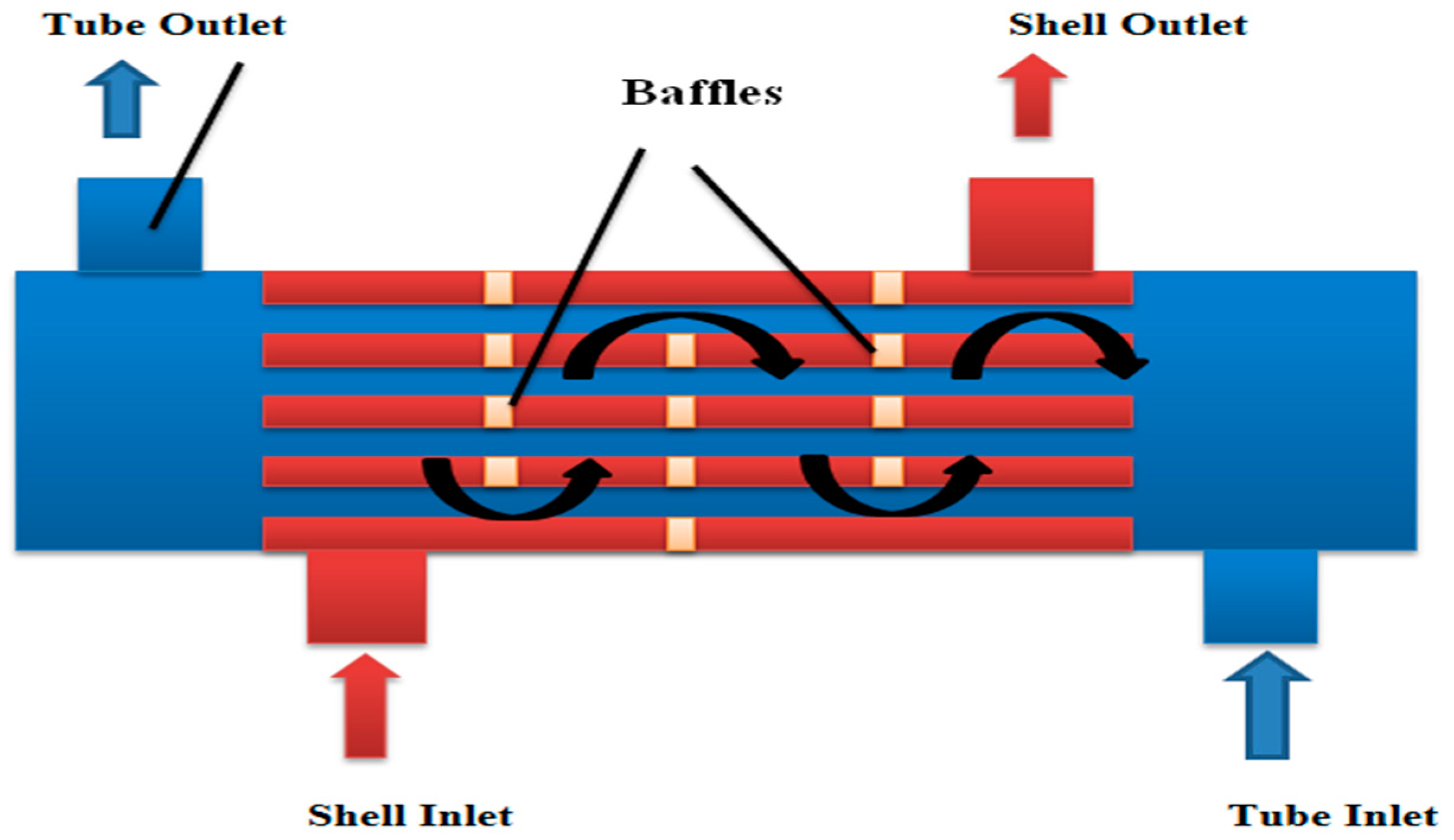
2. Geometry Description and Mathematical Model
3. Numerical Methodology
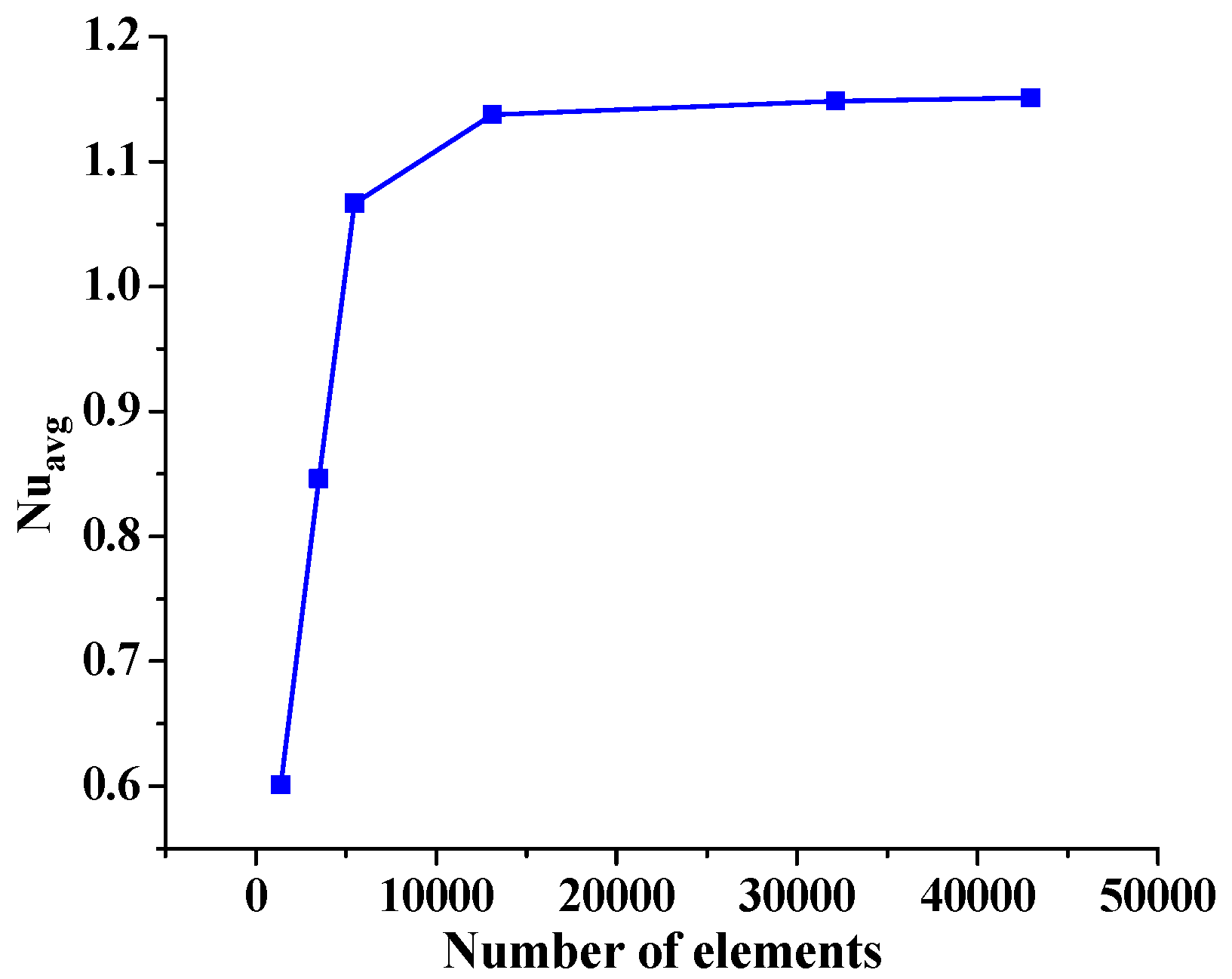
3.1. Grid Test
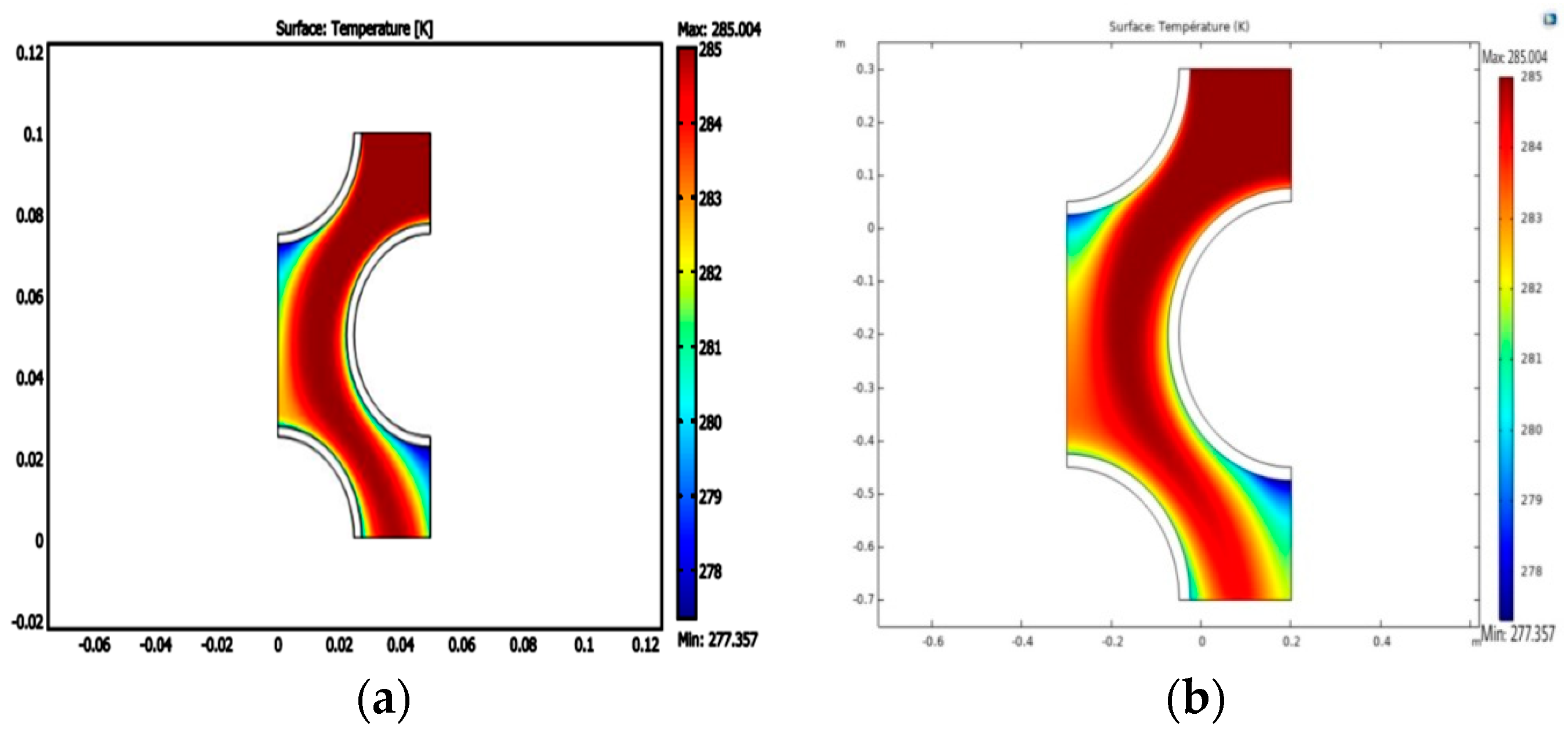
3.2. Validation
4. Results and Discussion
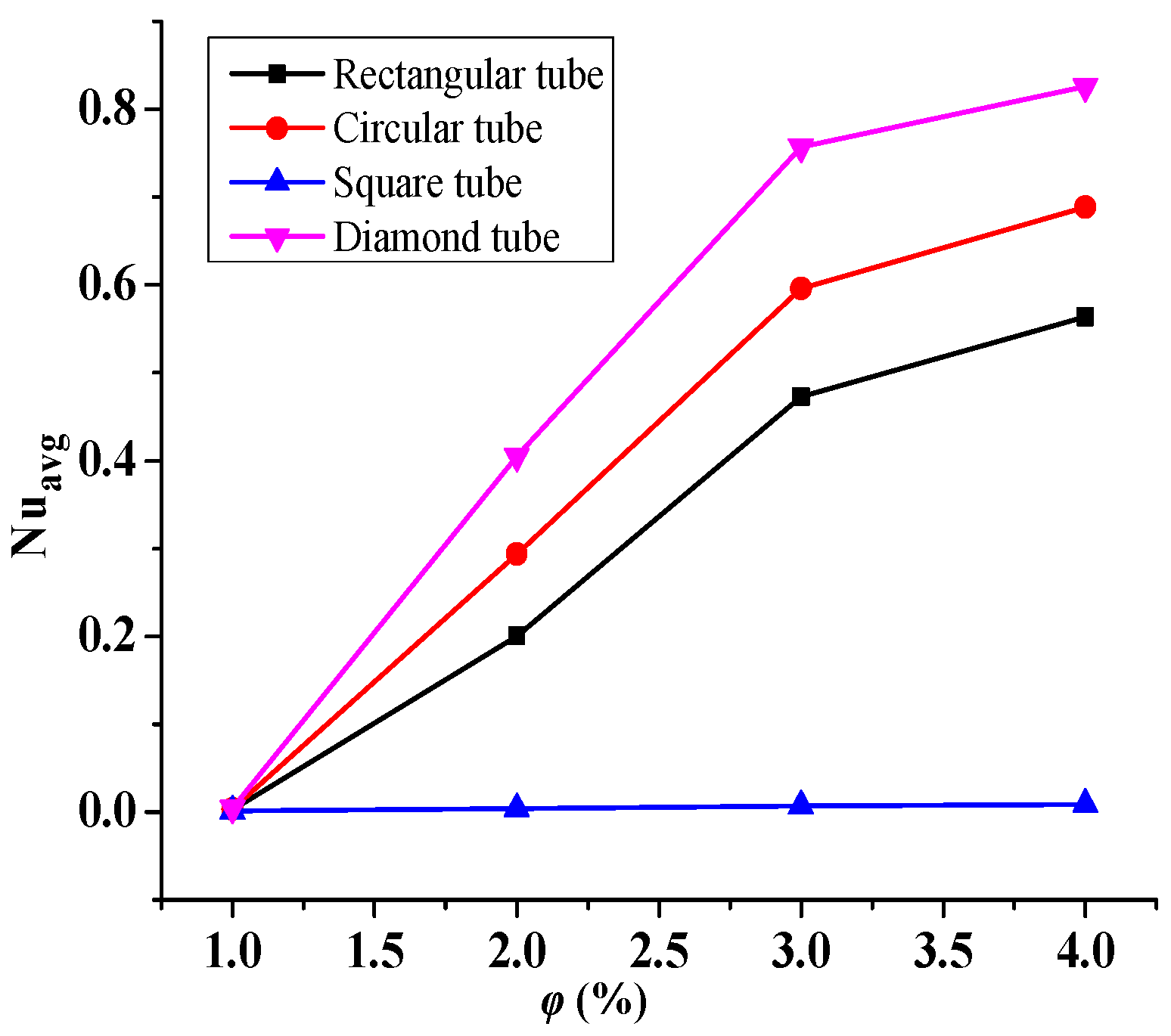
4.1. Effect of Nanofluid Volume Fraction
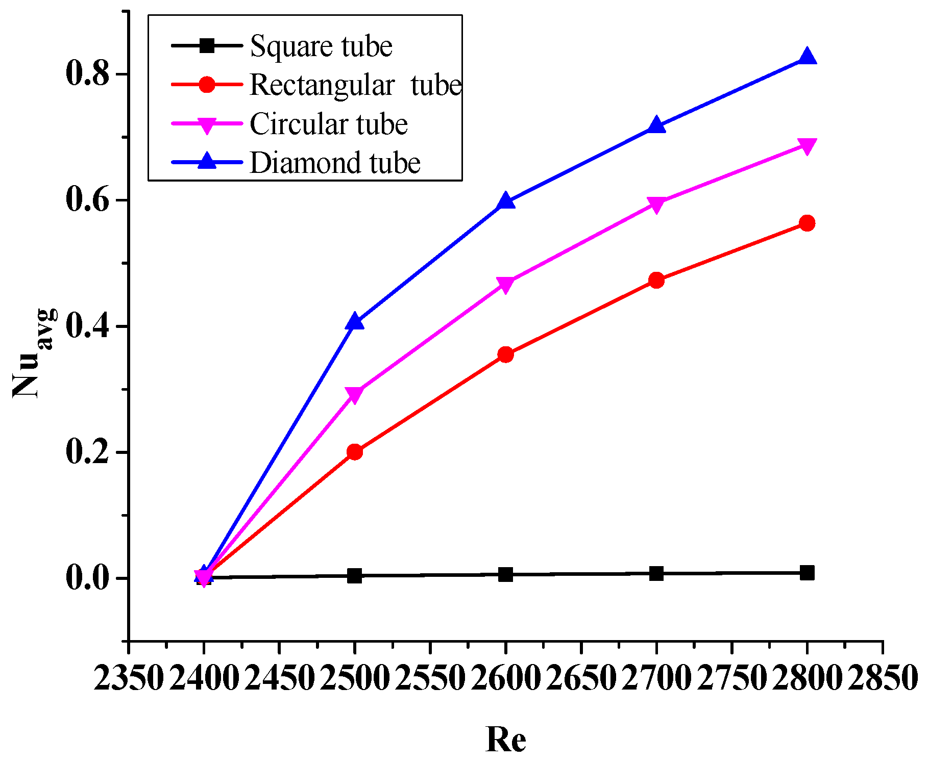
4.2. Reynolds Number Effect
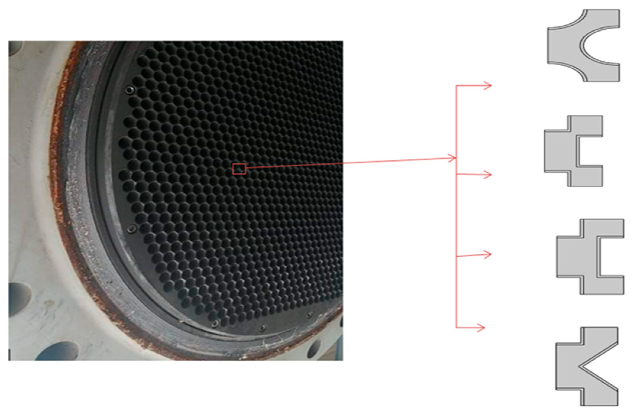
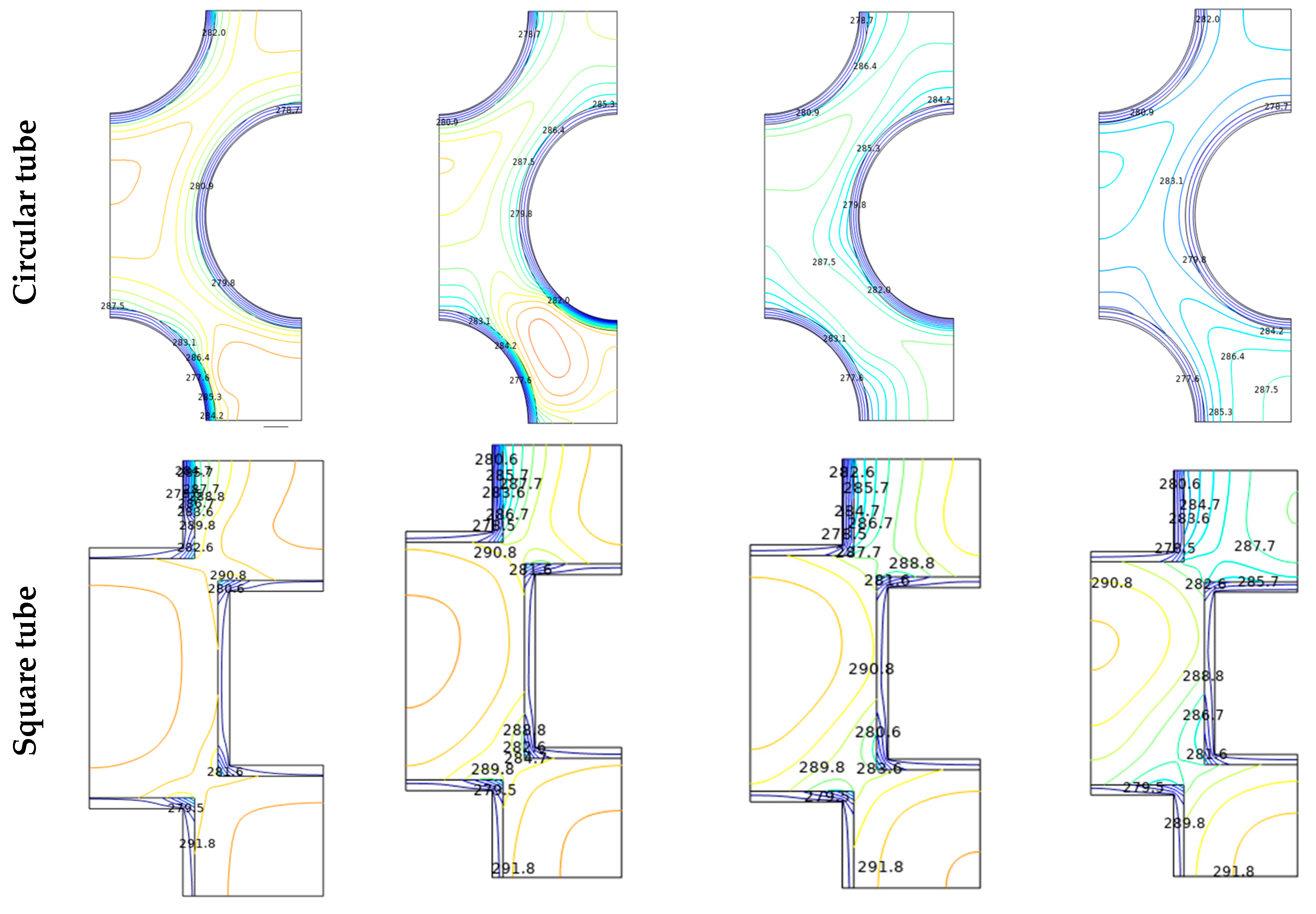
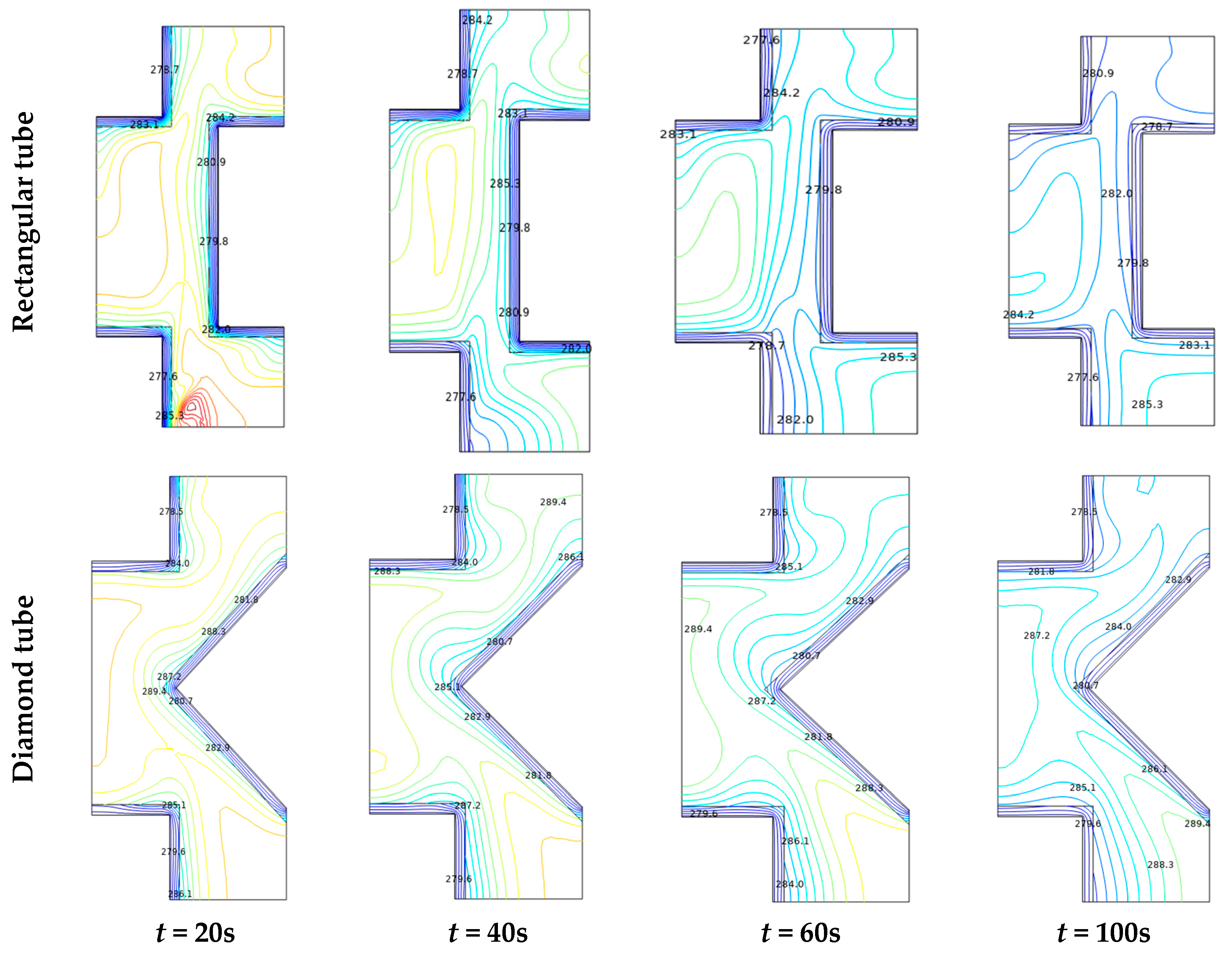
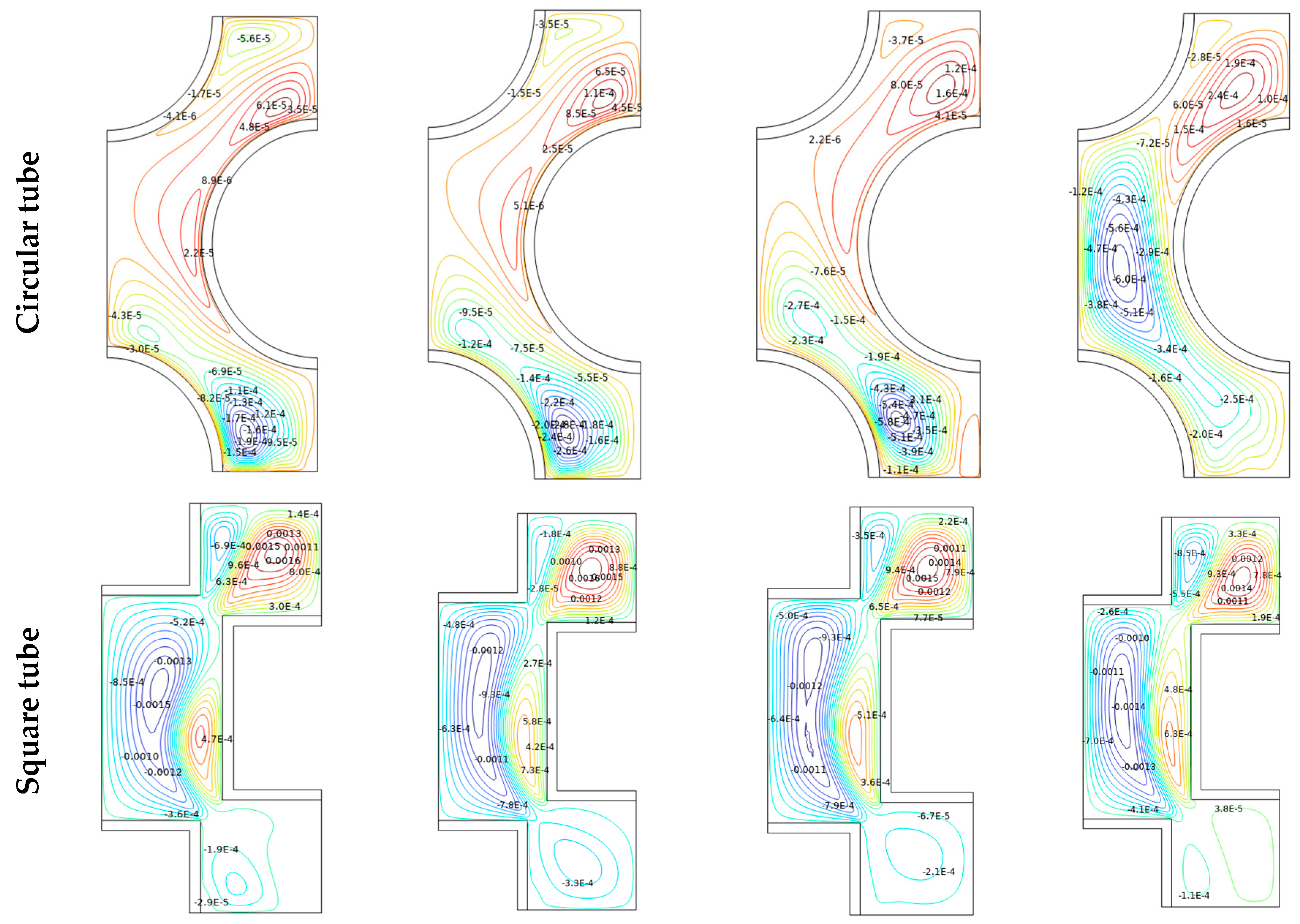
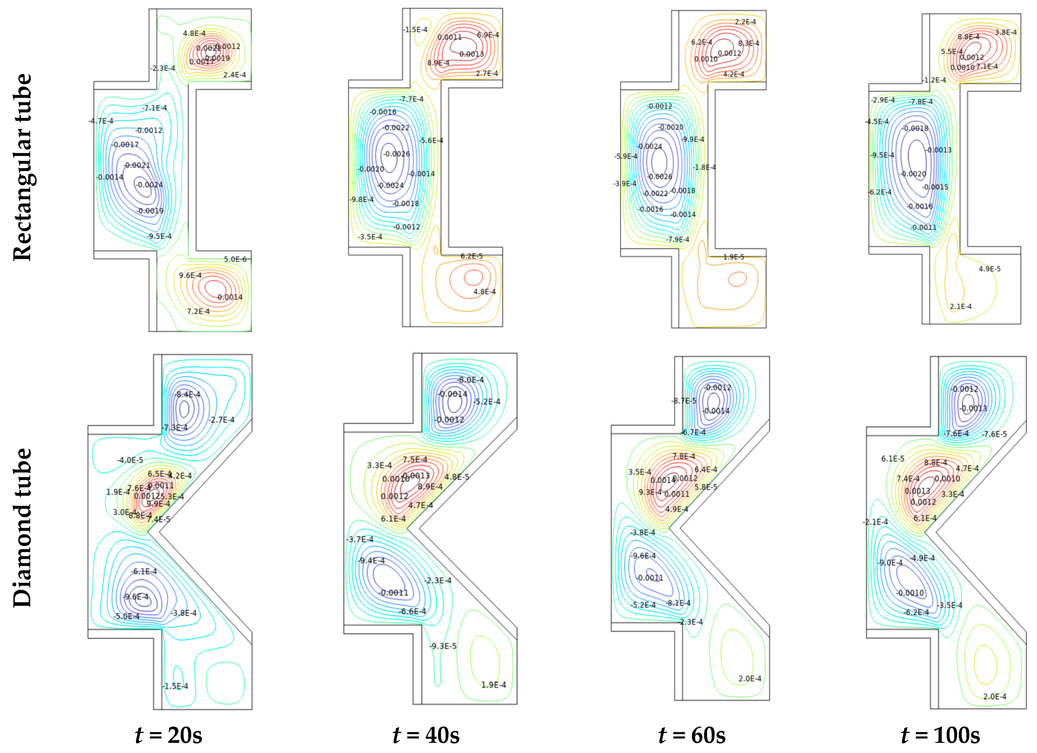
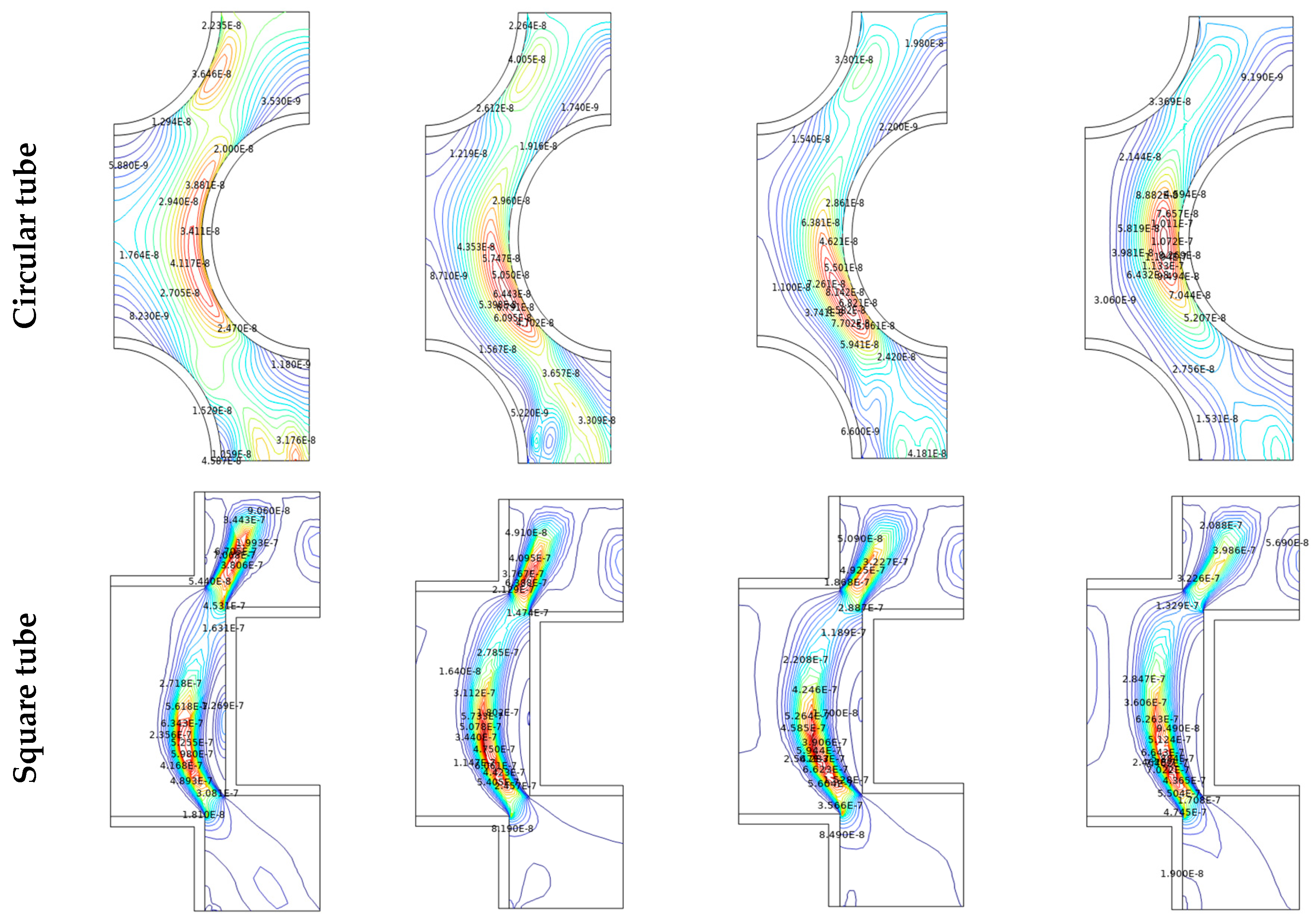
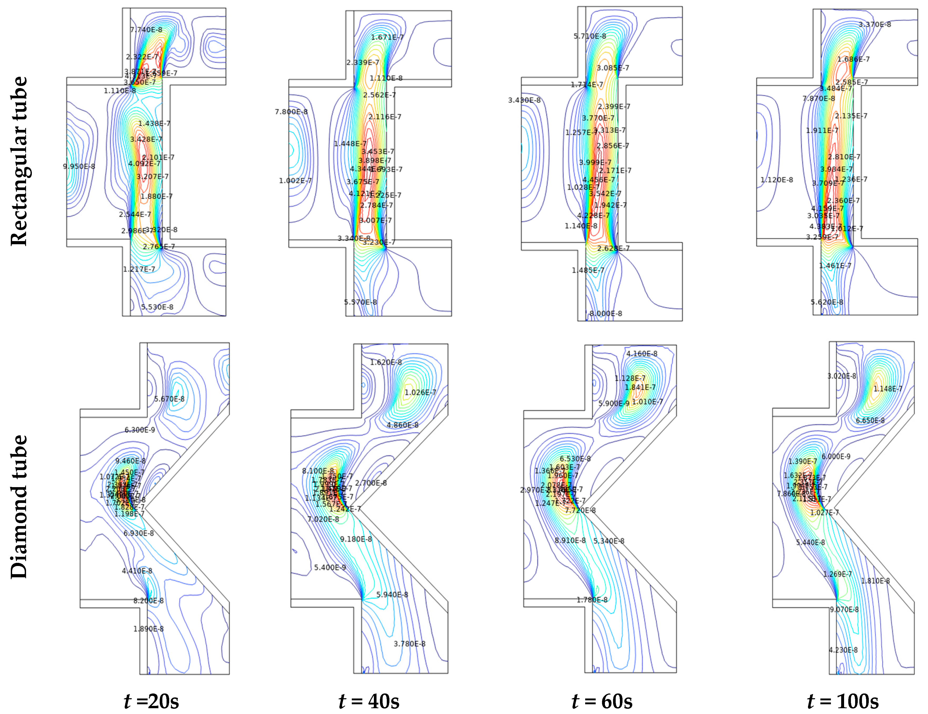
4.3. The Effect of Tube Shape
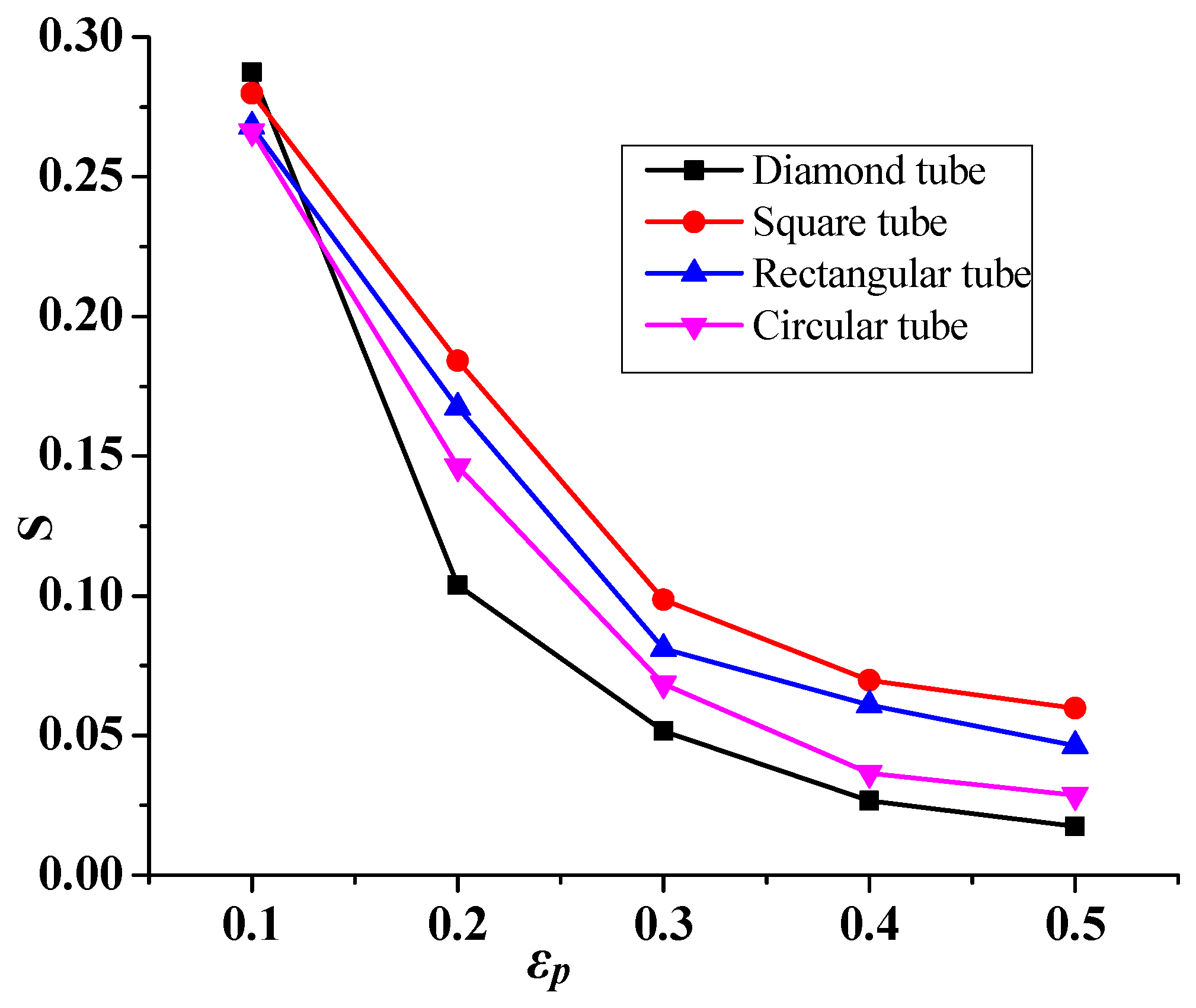
4.4. Entropy Generation
5. Conclusions
- The heat transfer rises with the growing fluid velocity (function of Re).
- The heat transfer rises with growing nanoparticle concentration. Compared to the circular tubes, the heat transfer enhancement goes up to 103.07% with a particle concentration of 2%.
- The diamond-shaped tube only offers superior performance in heat transfer compared to all other shaped tubes.
- The diamond tube shape improves the heat exchanger performance by exhibiting the most decreases in entropy compared to the other shapes.
Author Contributions
Funding
Institutional Review Board Statement
Informed Consent Statement
Data Availability Statement
Acknowledgments
Conflicts of Interest
Abbreviations
| Nomenclature | |
| g | Acceleration due to gravitational (m·s−2) |
| H | Heat exchanger height (m) |
| Specific heat capacity at constant pressure (J/(kg·K)) | |
| Nu | Nusselt number (average) |
| p | pressure (Pa) |
| Pr | Prandtl number |
| Re | Reynolds number |
| t | time (s) |
| T | temperature (K) |
| q | heat flux by conduction (W/m2) |
| heat flux by radiation (W/m2) | |
| u, v | components of velocity (m s−1) |
| x, y | Cartesian coordinates (m) |
| Greek symbols | |
| thermal diffusivity (m2·s−1) | |
| β | coefficient of thermal expansion (K−1) |
| dynamic viscosity (N m−2·s−1) | |
| kinematic viscosity (m2·s−1) | |
| fluid density (kg m−3) | |
| hybrid nanoparticles volume fraction (%) | |
| Dimensionless stream function | |
| θ | Dimensionless temperature |
| τ | viscous stress tensor (Pa) |
| ∇ | del operator |
References
- Bontemps, A.; Garrigue, A.; Goubier, C.; Huetz, J.; Marvillet, C.; Mercier, P.; Vidil, R. Echangeurs de Chaleur. In Définitions et Architecture Générale. France: Techniques de l’Ingénieur, Traité Génie Energétique; 1994; p. B2340. Available online: https://www.techniques-ingenieur.fr/base-documentaire/archives-th12/archives-thermique-industrielle-tiabec/archive-1/echangeurs-de-chaleur-b2340/architecture-generale-de-l-echangeur-b2340niv10002.html (accessed on 15 May 2023).
- Finkbeiner, F.; Gonard, T.; Filiol, B. Echangeurs Thermiques: Enjeux, Marchés, Technologie et Politique d’Innovation; Editions Européennes Thermique et Industrie (EETI): Paris, France, 1993. [Google Scholar]
- Labbadlia, O.; Laribi, B.; Chetti, B.; Hendrick, P. Numerical study of the influence of tube arrangement on the flow distribution in the header of shell and tube heat exchangers. Appl. Therm. Eng. 2017, 126, 315–321. [Google Scholar] [CrossRef]
- He, Z.; Fang, X.; Zhang, Z.; Gao, X. Numerical investigation on performance comparison of non-Newtonian fluid flow in vertical heat exchangers combined helical baffle with elliptic and circular tubes. Appl. Therm. Eng. 2016, 100, 84–97. [Google Scholar] [CrossRef]
- Qiu, Y.; Li, M.-J.; Wang, W.-Q.; Du, B.-C.; Wang, K. An experimental study on the heat transfer performance of a prototype molten-salt rod baffle heat exchanger for concentrated solar power. Energy 2018, 156, 63–72. [Google Scholar] [CrossRef]
- Yang, J.-F.; Zeng, M.; Wang, Q.-W. Numerical investigation on shell-side performances of combined parallel and serial two shell pass shell-and-tube heat exchangers with continuous helical baffles. Appl. Energy 2015, 139, 163–174. [Google Scholar] [CrossRef]
- Ayub, Z.H.; Yang, D.; Khan, T.S.; Al-Hajri, E.; Ayub, A.H. Performance characteristics of a novel shell and tube heat exchanger with shell side interstitial twisted tapes for viscous fluids application. Appl. Therm. Eng. 2018, 134, 248–255. [Google Scholar] [CrossRef]
- Biswas, N.; Manna, N.K.; Chamkha, A.J.; Mandal, D.K. Effect of surface waviness on MHD thermo-gravitational convection of Cu−Al2O3−water hybrid nanofluid in a porous oblique enclosure. Phys. Scr. 2021, 96, 105002. [Google Scholar] [CrossRef]
- Mandal, D.K.; Biswas, N.; Manna, N.K.; Gorla, R.S.R.; Chamkha, A.J. Hybrid nanofluid magnetohydrodynamic mixed convection in a novel W-shaped porous system. Int. J. Numer. Meth. Heat Fluid Flow 2023, 33, 510–544. [Google Scholar] [CrossRef]
- Horvat, A.; Leskovar, M.; Mavko, B. Comparison of heat transfer conditions in tube bundle cross-flow for different tube shapes. Int. J. Heat Mass Transf. 2006, 49, 1027–1038. [Google Scholar] [CrossRef]
- Mebarek-Oudina, F.; Preeti; Sabu, A.S.; Vaidya, H.; Lewis, R.W.; Areekara, S.; Mathew, A.; Ismail, A.I. Hydromagnetic flow of magnetite-water nano-fluid utilizing adapted Buongiorno model. Int. J. Mod. Phys. B 2023, 2450003. [Google Scholar] [CrossRef]
- Fazelpour, F.; Vafaeipour, M.; Rahbari, O. CFD simulation of hydrodynamics of gas-solid two-phase flow for different geometries of solid particles. In Proceedings of the 5th International Congress on Energy and Environment Engineering and Management, Lisbon, Portugal, 17–19 July 2013. [Google Scholar]
- Skoglund, T.; Årzén, K.-E.; Dejmek, P. Dynamic object-oriented heat exchanger models for simulation of fluid property transitions. Int. J. Heat Mass Transf. 2006, 49, 2291–2303. [Google Scholar] [CrossRef]
- Raza, J.; Mebarek-Oudina, F.; Lund, L.A. The flow of magnetised convective Casson liquid via a porous channel with shrinking and stationary walls. Pramana—J. Phys. 2022, 96, 229. [Google Scholar] [CrossRef]
- Zaversky, F.; Sánchez, M.; Astrain, D. Object-oriented modeling for the transient response simulation of multi-pass shell-and-tube heat exchangers as applied in active indirect thermal energy storage systems for concentrated solar power. Energy 2014, 65, 647–664. [Google Scholar] [CrossRef]
- Shahdad, I.; Fazelpour, F. Numerical analysis of the surface and geometry of plate fin heat exchangers for increasing heat transfer rate. Int. J. Energy Environ. Eng. 2018, 9, 155–167. [Google Scholar] [CrossRef]
- Xie, S.; Liang, Z.; Zhang, L.; Wang, Y. A numerical study on heat transfer enhancement and flow structure in enhanced tube with cross ellipsoidal dimples. Int. J. Heat Mass Transf. 2018, 125, 434–444. [Google Scholar] [CrossRef]
- Matos, R.; Laursen, T.; Vargas, J.; Bejan, A. Three-dimensional optimization of staggered finned circular and elliptic tubes in forced convection. Int. J. Therm. Sci. 2004, 43, 477–487. [Google Scholar] [CrossRef]
- Matos, R.; Vargas, J.; Laursen, T.; Saboya, F. Optimization study and heat transfer comparison of staggered circular and elliptic tubes in forced convection. Int. J. Heat Mass Transf. 2001, 44, 3953–3961. [Google Scholar] [CrossRef]
- Nouri-Borujerdi, A.; Lavasani, A. Experimental study of forced convection heat transfer from a cam shaped tube in cross flows. Int. J. Heat Mass Transf. 2007, 50, 2605–2611. [Google Scholar] [CrossRef]
- Nouri-Borujerdi, A.; Lavasani, A.M. Pressure loss and heat transfer characterization of a cam-shaped cylinder at different orientations. J. Heat Transf. 2008, 130, 124503. [Google Scholar] [CrossRef]
- Mohanty, R.L.; Swain, A.; Das, M.K. Thermal performance of mixed tube bundle composed of circular and elliptical tubes. Therm. Sci. Eng. Prog. 2018, 5, 492–505. [Google Scholar] [CrossRef]
- Dharmaiah, G.; Mebarek-Oudina, F.; Balamurugan, K.S.; Vedavathi, N. Numerical Analysis of the Magnetic Dipole Effect on a Radiative Ferromagnetic Liquid Flowing over a Porous Stretched Sheet. Fluid Dyn. Mater. Process. 2023. [Google Scholar] [CrossRef]
- Li, B.; Feng, B.; He, Y.-L.; Tao, W.-Q. Experimental study on friction factor and numerical simulation on flow and heat transfer in an alternating elliptical axis tube. Appl. Therm. Eng. 2006, 26, 2336–2344. [Google Scholar] [CrossRef]
- Bouris, D.; Papadakis, G.; Bergeles, G. Numerical evaluation of alternate tube configurations for particle deposition rate reduction in heat exchanger tube bundles. Int. J. Heat Fluid Flow 2001, 22, 525–536. [Google Scholar] [CrossRef]
- Moawed, M. Experimental study of forced convection from helical coiled tubes with different parameters. Energy Conv. Manag. 2011, 52, 1150–1156. [Google Scholar] [CrossRef]
- Rosen, M.; Dincer, I. Exergy methods for assessing and comparing thermal storage systems. Int. J. Energy Res. 2003, 27, 415–430. [Google Scholar] [CrossRef]
- Khan, M.G.; Fartaj, A.; Ting, D.S.-K. An experimental characterization of cross-flow cooling of air via an in-line elliptical tube array. Int. J. Heat Fluid Flow 2004, 25, 636–648. [Google Scholar] [CrossRef]
- Harris, D.K.; Goldschmidt, V.W. Measurements of the overall heat transfer from combustion gases confined within elliptical tube heat exchangers. Exp. Therm. Fluid Sci. 2002, 26, 33–37. [Google Scholar] [CrossRef]
- Tao, Y.; He, Y.; Wu, Z.; Tao, W. Three-dimensional numerical study and field synergy principle analysis of wavy fin heat exchangers with elliptic tubes. Int. J. Heat Fluid Flow 2007, 28, 1531–1544. [Google Scholar] [CrossRef]
- Li, Z.; Davidson, J.; Mantell, S. Numerical simulation of flow field and heat transfer of streamlined cylinders in cross flow. In ASME 2005 Summer Heat Transfer Conference Collocated with the ASME 2005 Pacific Rim Technical Conference and Exhibition on Integration and Packaging of MEMS, NEMS, and Electronic Systems 2005; American Society of Mechanical Engineers: New York, NY, USA, 2005; pp. 531–541. [Google Scholar]
- Kumar, N.; Jhinge, P.K. Effect of segmental baffles at different orientation on the performances of single pass shell and tube heat exchanger. Int. J. Ing. Trends Technol. 2014, 15, 423–428. [Google Scholar]
- Raj, T.K.; Ganne, S. Shell side numerical analysis of a shell and tube heat exchanger considering the effects of baffle inclination angle on fluid flow. Therm. Sci. 2012, 16, 1165–1174. [Google Scholar] [CrossRef]
- Zhang, J.; He, Y.; Tao, W. 3D numerical simulation on shell-and-tube heat exchangers with middle-overlapped helical baffles and continuous baffles—Part II: Simulation results of periodic model and comparison between continuous and noncontinuous helical baffles. Int. J. Heat Mass Transf. 2009, 52, 5381–5389. [Google Scholar] [CrossRef]
- Sivarajan, C.; Rajasekaran, B.; Krishnamohan, N. Comparision of numerical heat transfer in conventional and helically baffled heat exchanger. IJERA 2012, 2, 1278–1282. [Google Scholar]
- Kwon, Y.H.; Kim, D.; Li, C.G.; Lee, J.K. Heat transfer and pressure drop characteristics of Nano fluids in a plate heat exchanger. J. Nano Sci. Nanotechnol. 2011, 11, 5769–5774. [Google Scholar] [CrossRef] [PubMed]
- Albadr, J.; Tayal, S.; Alasadi, M. Heat transfer through heat exchanger using Al2O3 nanofluid at different concentration. Case Stud. Therm. Eng. 2013, 1, 38–44. [Google Scholar] [CrossRef]
- Asadi, A.; Asadi, M.; Rezaniakolaei, A.; Rosendahl, L.A.; Afrand, M.; Wongwises, S. Heat transfer efficiency of Al2O3-MWCNT/thermal oil hybrid nanofluid as a cooling fluid in thermal and energy management applications: An experimental and theoretical investigation. Int. J. Heat Mass Transf. 2018, 117, 474–486. [Google Scholar] [CrossRef]
- Ghazanfari, V.; Imani, M.; Shadman, M.M.; Amini, Y.; Zahakifar, F. Numerical study on the thermal performance of the shell and tube heat exchanger using twisted tubes and Al2O3 nanoparticles. Prog. Nucl. Energy 2023, 155, 104526. [Google Scholar] [CrossRef]
- Multiphysics, C. Comsol Multiphysics User Guide, Version 4.3 a; COMSOL, AB: Stockholm, Sweden, 2012; pp. 39–40. [Google Scholar]
- Gourari, S.; Mebarek-Oudina, F.; Makinde, O.D.; Rabhi, M. Numerical Investigation of Gas-Liquid Two-Phase Flows in a Cylindrical Channel. Defect Diffus. Forum 2021, 409, 39–48. [Google Scholar] [CrossRef]
- Salari, M.; Malekshah, E.H.; Malekshah, M.H. Natural convection in a rectangular enclosure filled by two immiscible fluids of air and Al2O3-water nanofluid heated partially from side walls. Alex. Eng. J. 2018, 57, 1401–1412. [Google Scholar] [CrossRef]
- Waini, I.; Ishak, A.; Pop, I. Hybrid nanofluid flow and heat transfer over a nonlinear permeable stretching/shrinking surface. Int. J. Numer. Methods Heat Fluid Flow 2019, 29, 3110–3127. [Google Scholar] [CrossRef]
- Chabani, I.; Mebarek-Oudina, F.; Vaidya, H.; Ismail, A.I. Numerical analysis of magnetic hybrid Nano-fluid natural convective flow in an adjusted porous trapezoidal enclosure. J. Magn. Magn. Mater. 2022, 564, 170142. [Google Scholar] [CrossRef]
- Mebarek-Oudina, F.; Chabani, I. Review on Nano-fluids applications and heat transfer enhancement techniques in different enclosures. J. Nanofluids 2022, 11, 155–168. [Google Scholar] [CrossRef]
- Khan, U.; Mebarek-Oudina, F.; Zaib, A.; Ishak, A.; Abu Bakar, S.; Sherif, E.M.; Baleanu, D. An exact solution of a Casson fluid flow induced by dust particles with hybrid nanofluid over a stretching sheet subject to Lorentz forces. Waves Random Complex Media 2022. [Google Scholar] [CrossRef]
- Roy, P.; Mondal, A. Analysis of Shell and Tube heat exchanger design using Comsol Multiphysics. Int. J. Sci. Appl. Res. 2016, 3, 70–82. [Google Scholar]
- Mebarek-Oudina, F.; Fares, R.; Aissa, A.; Lewis, R.W.; Abu-Hamdeh, N. Entropy and convection effect on magnetized hybrid nano-liquid flow inside a trapezoidal cavity with zigzagged wall. Int. Comm. Heat Mass Trans. 2021, 125, 105279. [Google Scholar] [CrossRef]
- Mebarek-Oudina, F.; Fares, R.; Choudhari, R. Convection Heat Transfer of MgO-Ag/Water Magneto-Hybrid Nanoliquid Flow into a Special Porous Enclosure. Alg. J. Renew. Energ. Sust. Develop. 2020, 2, 84–95. [Google Scholar]
- Shafiq, A.; Mebarek-Oudina, F.; Sindhu, T.N.; Rassoul, G. Sensitivity analysis for Walters’ B nanoliquid flow over a radiative Riga surface by RSM. Sci. Iran. 2022, 29, 1236–1249. [Google Scholar] [CrossRef]
- Mebarek-Oudina, F. Convective Heat Transfer of Titania Nanofluids of different base fluids in Cylindrical Annulus with discrete Heat Source. Heat Transf.-Asian Res. 2019, 48, 135–147. [Google Scholar] [CrossRef]
- Ramesh, K.; Mebarek-Oudina, F.; Ismail, A.I.; Jaiswal, B.R.; Warke, A.S.; Lodhi, R.K.; Sharma, T. Computational analysis on radiative non-Newtonian Carreau nanofluid flow in a microchannel under the magnetic properties. Sci. Iran. 2023, 30, 376–390. [Google Scholar]
- Ali, A.; Mebarek-Oudina, F.; Barman, A.; Das, S.; Ismail, A.I. Peristaltic transportation of hybrid nano-blood through a ciliated micro-vessel subject to heat source and Lorentz force. J. Therm. Anal. Calorim. 2023, 36, 101510. [Google Scholar] [CrossRef]
- Mebarek-Oudina, F.; Chabani, I. Review on Nano Enhanced PCMs: Insight on nePCM Application in Thermal Management/Storage Systems. Energies 2023, 16, 1066. [Google Scholar] [CrossRef]


| ρ | k (W/m k) | σ (s/m) | ||
|---|---|---|---|---|
| Water | 997.1 | 0.613 | 4179 | 5.5 × 10⁻⁶ |
| MWCNT | 2100 | 3000 | 711 | 10−7 |
| 3950 | 36.96 | 785.02 |
| Mesh | Element Number | Average Nusselt Number |
|---|---|---|
| Extra coarse | 1398 | 0.6011 |
| Very coarse | 3501 | 0.84613 |
| Coarse | 5487 | 1.0666 |
| normal | 13,108 | 1.13758 |
| Fine | 32,128 | 1.14863 |
| Very fine | 42,948 | 1.15084 |
Disclaimer/Publisher’s Note: The statements, opinions and data contained in all publications are solely those of the individual author(s) and contributor(s) and not of MDPI and/or the editor(s). MDPI and/or the editor(s) disclaim responsibility for any injury to people or property resulting from any ideas, methods, instructions or products referred to in the content. |
© 2023 by the authors. Licensee MDPI, Basel, Switzerland. This article is an open access article distributed under the terms and conditions of the Creative Commons Attribution (CC BY) license (https://creativecommons.org/licenses/by/4.0/).
Share and Cite
Bouselsal, M.; Mebarek-Oudina, F.; Biswas, N.; Ismail, A.A.I. Heat Transfer Enhancement Using Al2O3-MWCNT Hybrid-Nanofluid inside a Tube/Shell Heat Exchanger with Different Tube Shapes. Micromachines 2023, 14, 1072. https://doi.org/10.3390/mi14051072
Bouselsal M, Mebarek-Oudina F, Biswas N, Ismail AAI. Heat Transfer Enhancement Using Al2O3-MWCNT Hybrid-Nanofluid inside a Tube/Shell Heat Exchanger with Different Tube Shapes. Micromachines. 2023; 14(5):1072. https://doi.org/10.3390/mi14051072
Chicago/Turabian StyleBouselsal, Maissa, Fateh Mebarek-Oudina, Nirmalendu Biswas, and Abdel Aziz I. Ismail. 2023. "Heat Transfer Enhancement Using Al2O3-MWCNT Hybrid-Nanofluid inside a Tube/Shell Heat Exchanger with Different Tube Shapes" Micromachines 14, no. 5: 1072. https://doi.org/10.3390/mi14051072