
Adaptive Dynamic Analysis of MEMS Gyroscope Random Noise Based on PID-DAVAR
Abstract
:1. Introduction
2. Allan Variance Principle
2.1. Principle of Conventional Allan Variance
2.2. Characterization of Five Typical Random Noise Terms
- 1.
- Quantization noise refers to a high-frequency noise generated during the conversion of digital signals to analog signals. The Allan variance is expressed as:
- 2.
- Angle random walk is high-frequency noise caused by MEMS gyro angular rate random white noise integration. The Allan variance is expressed as:
- 3.
- Bias instability refers to the low-frequency bias drift caused by the flicker noise of electronic circuits, environmental noise, and other components. The Allan variance is expressed as:
- 4.
- Rate random walk refers to the random error generated by integrating the power spectral density of the bandwidth angular acceleration signal. The Allan variance is expressed as:
- 5.
- Rate ramp refers to the extremely slow monotonic change of the MEMS gyroscope during the long-term output process. The Allan variance is expressed as:
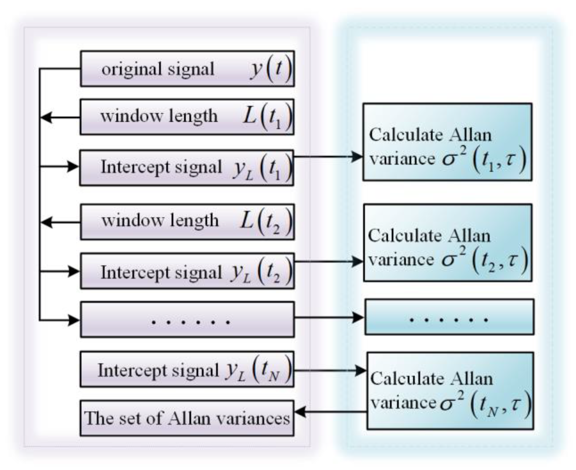
3. Principle of DAVAR
- (1)
- Fix an analysis point, let ;
- (2)
- Take the analysis point as the center, the fixed length is selected to intercept the original output signal;
- (3)
- Take the signal intercepted in step (2) as the research object, the Allan variance is calculated;
- (4)
- Continue to select another time analysis point, namely . The selection of should make the intercepted signal data overlap with the intercepted data of the previous time analysis point , repeat steps (2)~(4) to obtain Allan variance . Analogously, piecewise estimation is performed through a moving window, and the Allan variance set is obtained by multiple calculations;
- (5)
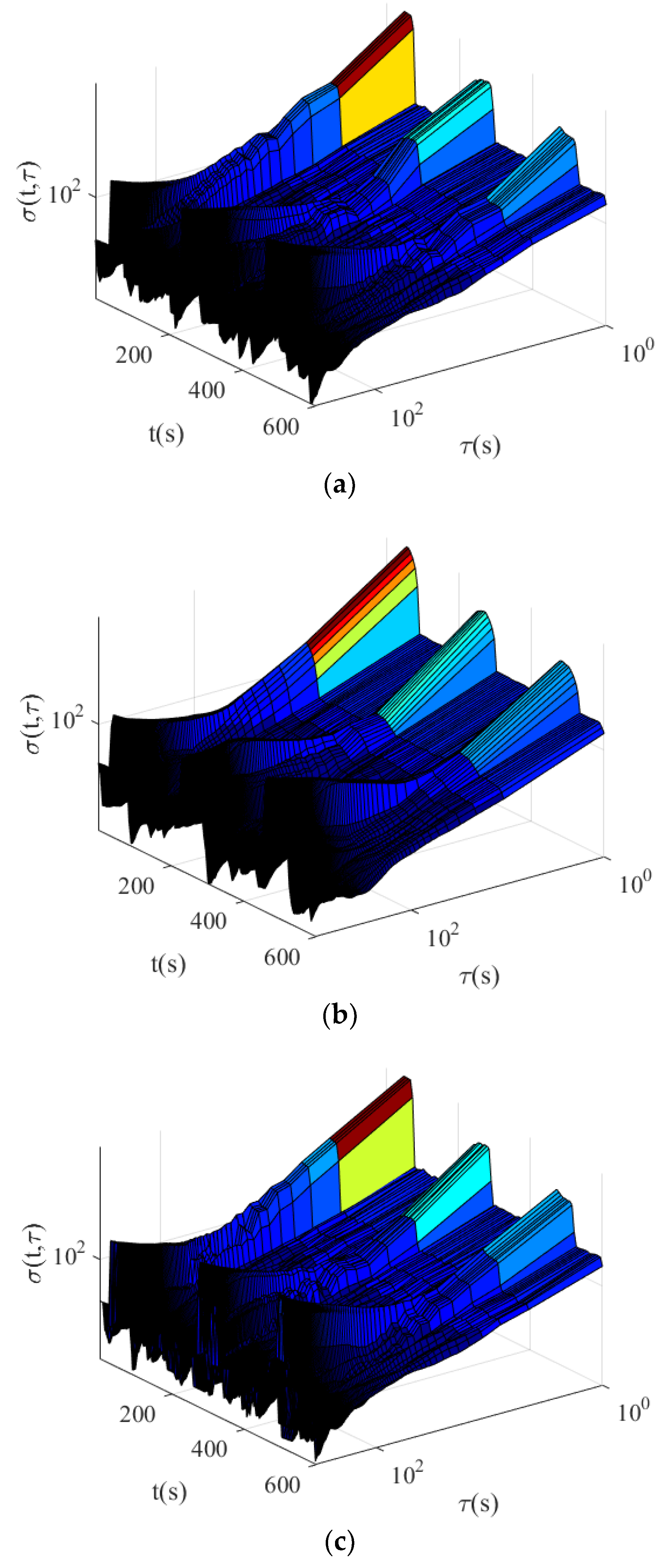
- The Allan variance set are arranged in chronological order, which corresponds to different time analysis points and different interception intervals . It is reflected in the form of a 3D graph, which characterizes the stability of real-time measurement of the MEMS gyroscope’s signal.
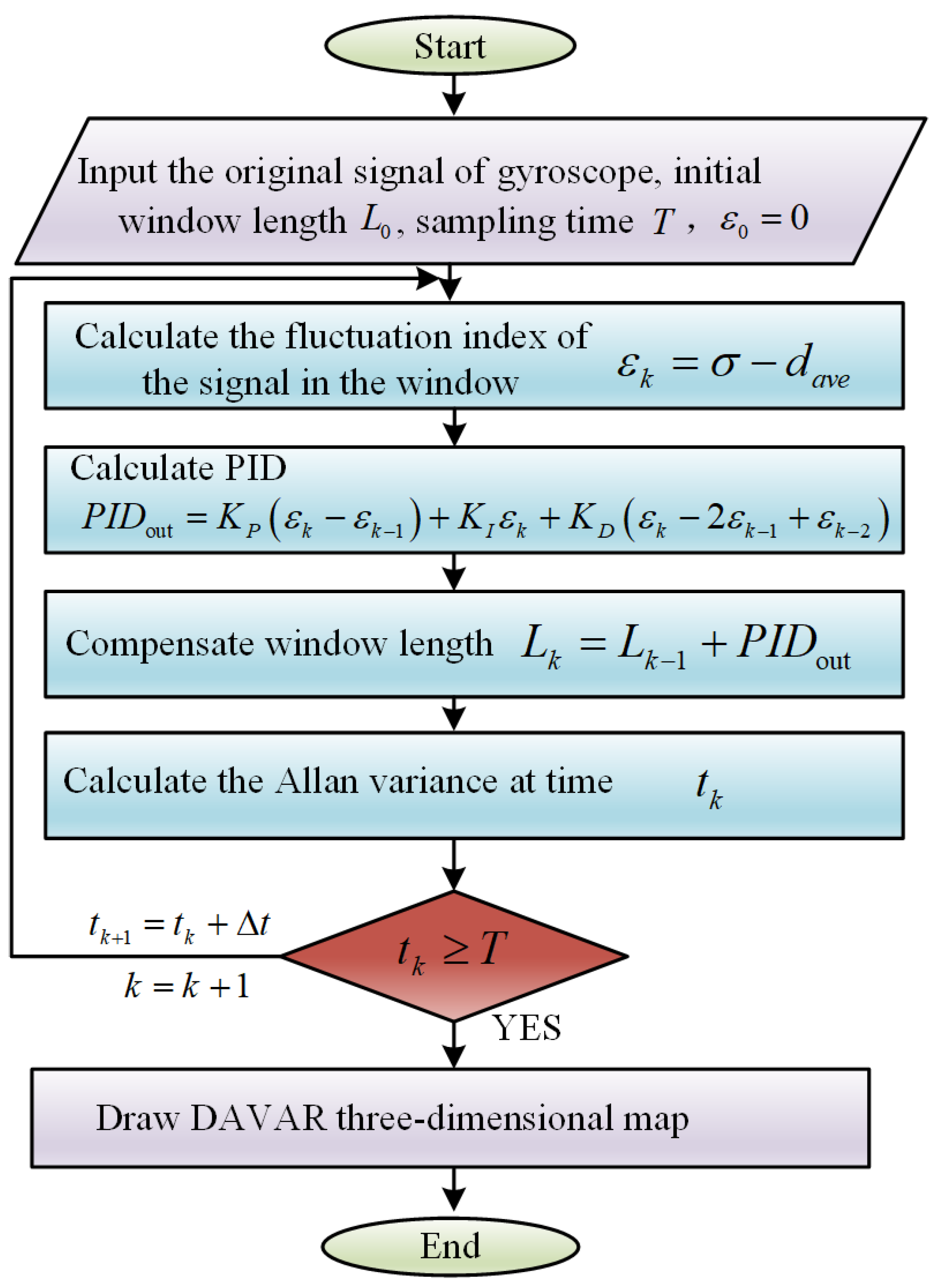
4. Dynamic Allan Variance Based on Adaptive PID Principle
4.1. PID Principle in PID-DAVAR Adaptive Algorithm
4.2. PID-DAVAR Adaptive Algorithm
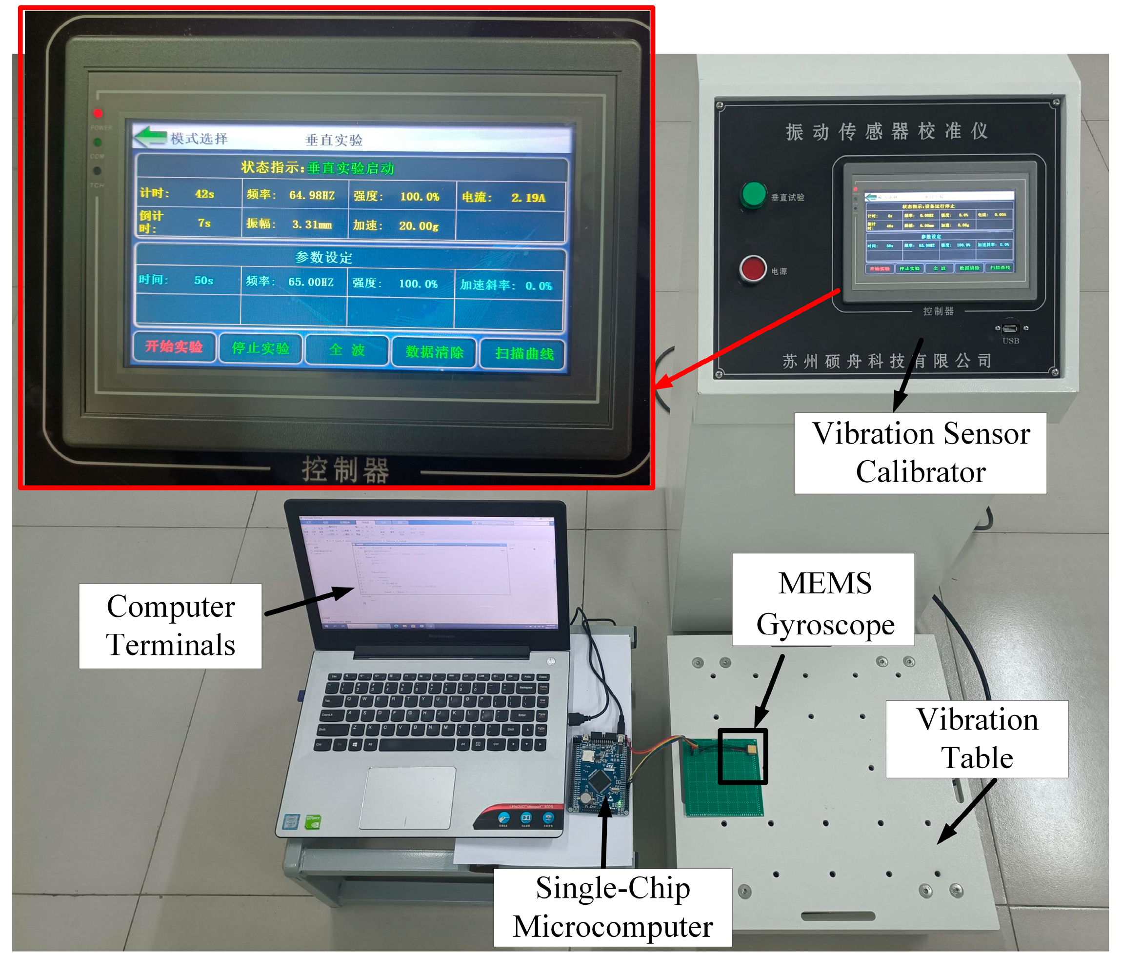
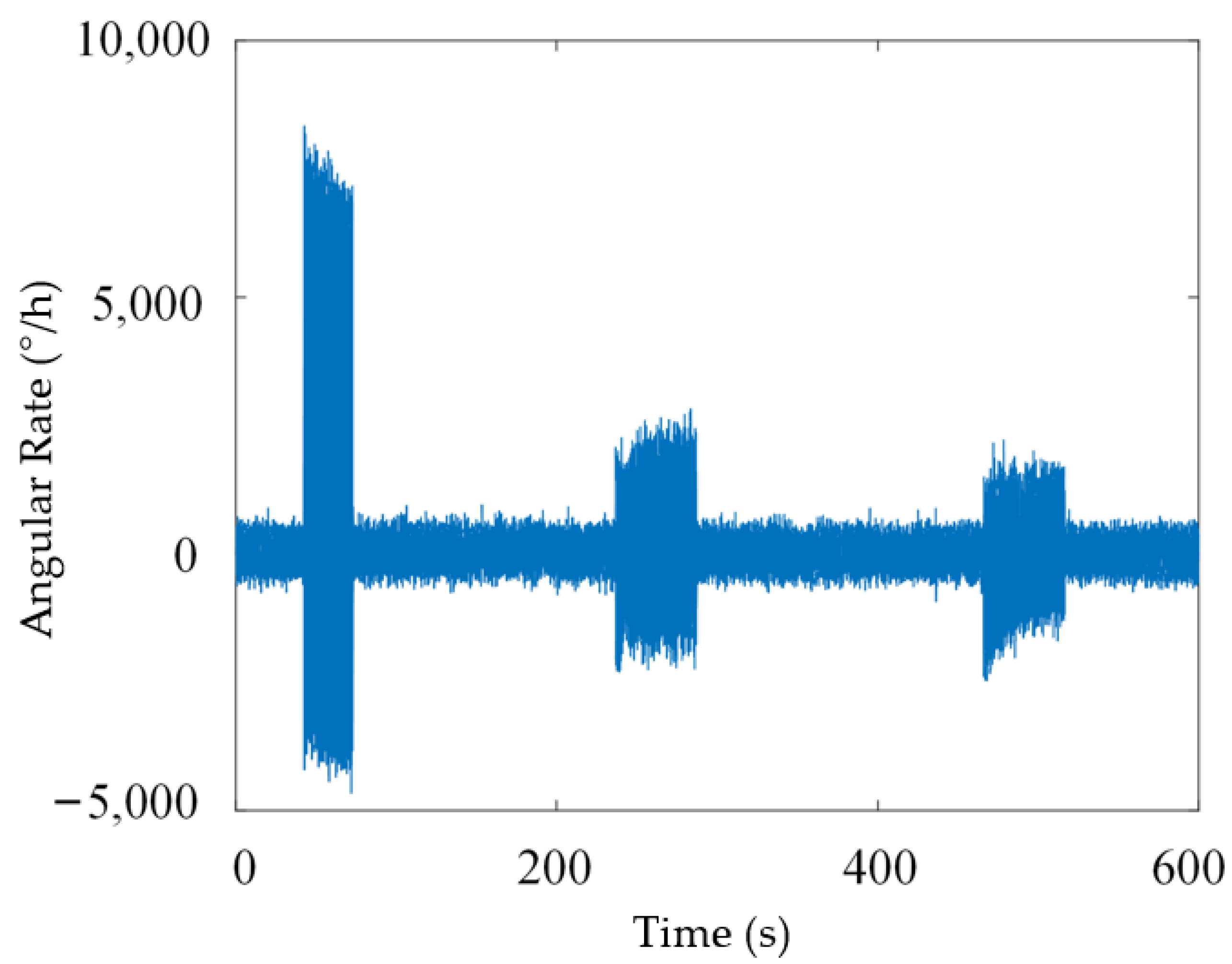
5. Experimental
6. Conclusions
Author Contributions
Funding
Conflicts of Interest
References
- Xue, L.; Yang, B.; Wang, X.; Shan, B.; Gao, J.; Chang, H.; Yao, Y. Design of Optimal Estimation Algorithm for Multi-sensor Fusion of a Redundant MEMS Gyro System. IEEE Sens. J. 2022, 23, 4577–4588. [Google Scholar] [CrossRef]
- Xue, L.; Wang, X.; Yang, B.; Yuan, W.; Yuan, G. Analysis of Correlation in MEMS Gyroscope Array and its Influence on Accuracy Improvement for the Combined Angular Rate Signal. Micromachines 2018, 9, 22. [Google Scholar] [CrossRef] [Green Version]
- Zhao, L.; Zhao, L. An Algorithm for Online Stochastic Error Modeling of Inertial Sensors in Urban Cities. Sensors 2023, 23, 1257. [Google Scholar] [CrossRef] [PubMed]
- Lam, Q.; Stamatakos, N.; Woodruff, C.; Ashton, S. Gyro Modeling and Estimation of Its Random Noise Sources. In Proceedings of the AIAA Guidance Mavigation, and Control Conference and Exhibit, Austin, TX, USA, 11–14 August 2003; p. 5562. [Google Scholar] [CrossRef]
- Vaccaro, R.; Zaki, A. Reduced-Drift Virtual Gyro from an Array of Low-Cost Gyros. Sensors 2017, 17, 352. [Google Scholar] [CrossRef] [PubMed] [Green Version]
- El-Sheimy, N.; Hou, H.; Niu, X. Analysis and Modeling of Inertial Sensors Using Allan Variance. IEEE Trans. Instrum. Meas. 2008, 57, 140–149. [Google Scholar] [CrossRef]
- Galleani, L. The dynamic Allan variance II: A fast computational algorithm. IEEE Trans. Ultrason. Ferroelectr. Freq. Control 2010, 57, 182–188. [Google Scholar] [CrossRef]
- Wang, L.; Zhang, C.; Gao, S.; Wang, T.; Lin, T.; Li, X. Application of Fast Dynamic Allan Variance for the Characterization of FOGs-Based Measurement While Drilling. Sensors 2016, 16, 2078. [Google Scholar] [CrossRef] [Green Version]
- Zhang, Q.; Wang, X.; Wang, S.; Pei, C. Application of Improved Fast Dynamic Allan Variance for the Characterization of MEMS Gyroscope on UAV. J. Sens. 2018, 2018, 2895187. [Google Scholar] [CrossRef]
- Gu, S.; Liu, J.; Zeng, Q.; Feng, S.; Lv, P. Dynamic Allan Variance Analysis Method with Time-Variant Window Length Based on Fuzzy Control. J. Sens. 2015, 2015, 564041. [Google Scholar] [CrossRef] [Green Version]
- Bai, Y.; Wang, X.; Jin, X.; Su, T.; Kong, J.; Zhang, B. Adaptive filtering for MEMS gyroscope with dynamic noise model. ISA Trans. 2020, 101, 430–441. [Google Scholar] [CrossRef]
- Rudyk, A.V.; Semenov, A.O.; Kryvinska, N.; Semenova, O.O.; Kvasnikov, V.P.; Safonyk, A.P. Strapdown Inertial Navigation Systems for Positioning Mobile Robots—MEMS Gyroscopes Random Errors Analysis Using Allan Variance Method. Sensors 2020, 20, 4841. [Google Scholar] [CrossRef]
- Jiang, C.; Chen, S.; Chen, Y.; Bo, Y.; Han, L.; Guo, J.; Feng, Z.; Zhou, H. Performance Analysis of a Deep Simple Recurrent Unit Recurrent Neural Network (SRU-RNN) in MEMS Gyroscope De-Noising. Sensors 2018, 18, 4471. [Google Scholar] [CrossRef] [Green Version]
- Sheng, G.; Gao, G.; Zhang, B. Application of Improved Wavelet Thresholding Method and an RBF Network in the Error Compensating of an MEMS Gyroscope. Micromachines 2019, 10, 608. [Google Scholar] [CrossRef] [PubMed] [Green Version]
- Ri, Y.G.; Sin, C.M.; Kang, J.G. Statistical modelling of rate gyros based on fully overlapping Allan variance. IET Sci. Meas. Technol. 2022, 16, 69–77. [Google Scholar] [CrossRef]
- Lv, P.; Liu, J.; Lai, J.; Huang, K. Allan variance method for gyro noise analysis using weighted least square algorithm. Optik 2015, 126, 2529–2534. [Google Scholar] [CrossRef]
- Dai, X.Y.; Chen, Z.G.; Xie, X. The Gyro Random Walk Analysis Based on Allan Variance. Appl. Mech. Mater. 2014, 668, 953–956. [Google Scholar] [CrossRef]
- Yafei, R.; Xizheng, K.; Yijie, L. MEMS Gyroscope Performance Estimate Based on Allan Variance. In Proceedings of the 2007 8th International Conference on Electronic Measurement and Instruments, Xi’an, China, 16–18 August 2007; pp. 1–260. [Google Scholar]
- Peng, W.-h.; Chen, W.-j.; Feng, L.-p. The recognition of MEMS gyroscope random error terms based on ALLAN variance. In Proceedings of the 2012 24th Chinese Control and Decision Conference (CCDC), Taiyuan, China, 23–25 May 2012; pp. 1603–1606. [Google Scholar]
- Dai, X.Y.; Chen, Z.G. The Gyro Error Analysis Based on Allan Variance. Appl. Mech. Mater. 2014, 644, 1369–1371. [Google Scholar] [CrossRef]
- Galleani, L.; Tavella, P. The characterization of clock behavior with the dynamic Allan variance. In Proceedings of the IEEE International Frequency Control Symposium and PDA Exhibition Jointly with the 17th European Frequency and Time Forum, Tampa, FL, USA, 4–8 May 2003; pp. 239–244. [Google Scholar]
- Zhang, Y.; Peng, C.; Mou, D.; Li, M.; Quan, W. An Adaptive Filtering Approach Based on the Dynamic Variance Model for Reducing MEMS Gyroscope Random Error. Sensors 2018, 18, 3943. [Google Scholar] [CrossRef] [Green Version]
- Song, J.; Shi, Z.; Wang, L.; Wang, H. Random Error Analysis of MEMS Gyroscope Based on an Improved DAVAR Algorithm. Micromachines 2018, 9, 373. [Google Scholar] [CrossRef] [Green Version]
- Wang, L.; Zhang, C.; Lin, T.; Li, X.; Wang, T. Characterization of a fiber optic gyroscope in a measurement while drilling system with the dynamic Allan variance. Meas. J. Int. Meas. Confed. 2015, 75, 263–272. [Google Scholar] [CrossRef]
- Qiao, B.; Ma, L.; Chen, L.; Hu, B. A PID-Based kNN Query Processing Algorithm for Spatial Data. Sensors 2022, 22, 7651. [Google Scholar] [CrossRef]
- Dong, J.; Duan, X. A Robust Control via a Fuzzy System with PID for the ROV. Sensors 2023, 23, 821. [Google Scholar] [CrossRef] [PubMed]
- Maddipatla, S.P.; Haeri, H.; Jerath, K.; Brennan, S. Fast Allan Variance (FAVAR) and Dynamic Fast Allan Variance (D-FAVAR) Algorithms for both Regularly and Irregularly Sampled Data. IFAC-PapersOnLine 2021, 54, 26–31. [Google Scholar] [CrossRef]
- Galleani, L.; Tavella, P. The dynamic Allan variance. IEEE Trans. Ultrason. Ferroelectr. Freq. Control 2009, 56, 450–464. [Google Scholar] [CrossRef] [PubMed]


| Main Noise Terms | Parameter Estimation | Slope Value |
|---|---|---|
| Quantization Noise | −1 | |
| Angular Random Walk | −1/2 | |
| Bias Instability | 0 | |
| Rate Random Walk | 1/2 | |
| Rate Ramp | 1 |
| Window Length | Mutation Start Point (s) | Mutation End Point (s) | Total Time (s) |
|---|---|---|---|
| Mutation Reference Value | 237.3 | 286.3 | |
| 1001 | 231.6 | 289.7 | 20.87 |
| 3001 | 218.8 | 296.5 | 89.46 |
| Adaptive Window | 235.5 | 285.4 | 8.65 |
| Title 1 | |||
| Reference Value | 1.72 | 18.89 | 102.28 |
| 1001 | 2.01 | 14.71 | 91.04 |
| 3001 | 1.99 | 7.86 | 34.07 |
| Self-Adaptation | 1.79 | 15.32 | 95.76 |
Disclaimer/Publisher’s Note: The statements, opinions and data contained in all publications are solely those of the individual author(s) and contributor(s) and not of MDPI and/or the editor(s). MDPI and/or the editor(s) disclaim responsibility for any injury to people or property resulting from any ideas, methods, instructions or products referred to in the content. |
© 2023 by the authors. Licensee MDPI, Basel, Switzerland. This article is an open access article distributed under the terms and conditions of the Creative Commons Attribution (CC BY) license (https://creativecommons.org/licenses/by/4.0/).
Share and Cite
Zhang, J.; Li, P.; Yu, Z.; Liu, J.; Zhang, X.; Zhuang, X. Adaptive Dynamic Analysis of MEMS Gyroscope Random Noise Based on PID-DAVAR. Micromachines 2023, 14, 792. https://doi.org/10.3390/mi14040792
Zhang J, Li P, Yu Z, Liu J, Zhang X, Zhuang X. Adaptive Dynamic Analysis of MEMS Gyroscope Random Noise Based on PID-DAVAR. Micromachines. 2023; 14(4):792. https://doi.org/10.3390/mi14040792
Chicago/Turabian StyleZhang, Jianing, Pinghua Li, Zhiyu Yu, Jinghao Liu, Xiaoyang Zhang, and Xuye Zhuang. 2023. "Adaptive Dynamic Analysis of MEMS Gyroscope Random Noise Based on PID-DAVAR" Micromachines 14, no. 4: 792. https://doi.org/10.3390/mi14040792