
Core–Shell Particles: From Fabrication Methods to Diverse Manipulation Techniques
 , ,
, ,  , and
, and 
Abstract
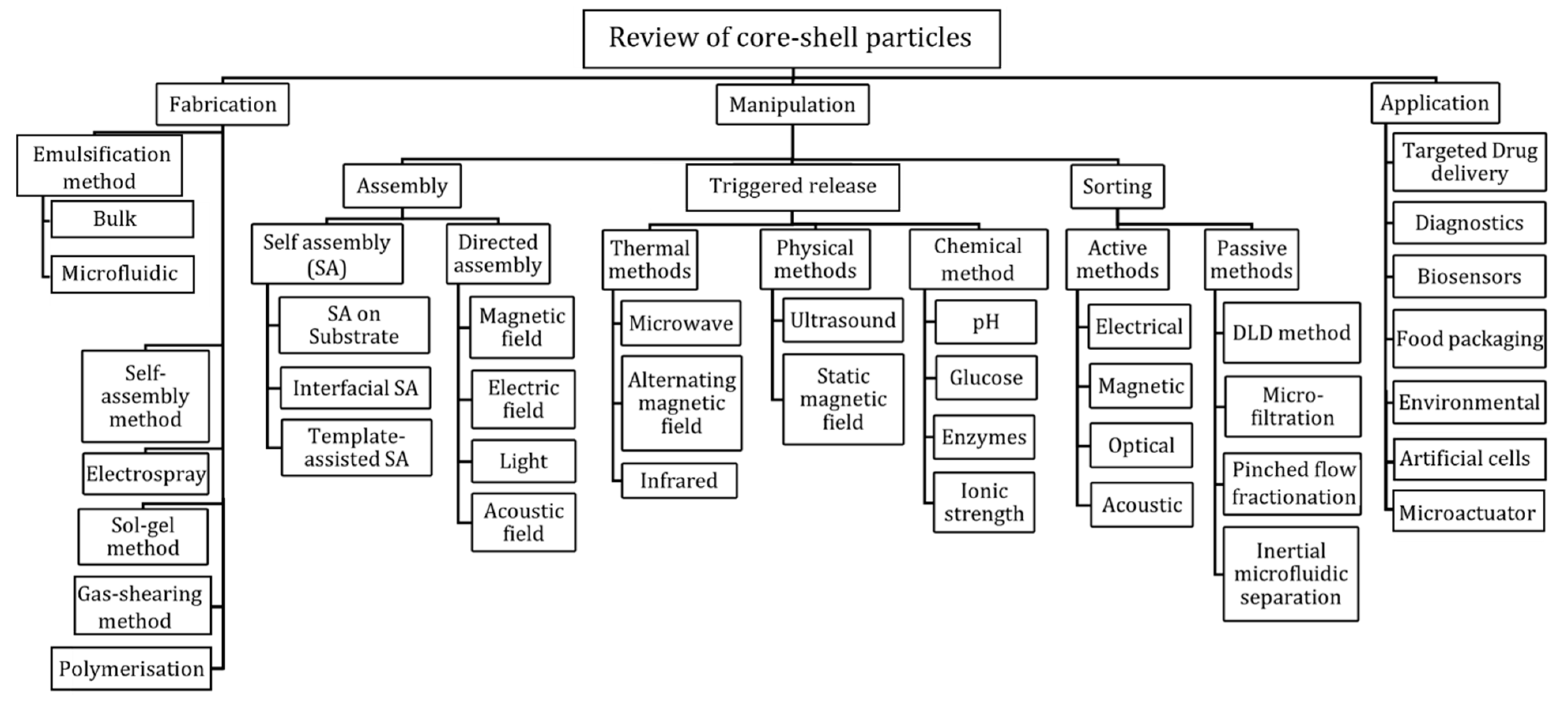
:1. Introduction
2. Fabrication Methods of Core–Shell Particles
2.1. Emulsification Method
2.1.1. Bulk Emulsification
2.1.2. Microfluidic Emulsification
Two-Step Emulsification
One-Step Emulsification
2.2. Polymerisation
2.3. Gas-Shearing
2.4. Sol–Gel Method
2.5. Electrospray
2.6. Self-Assembly Method
3. Assembly
3.1. Self-Assembly
3.1.1. Template-Assisted Self-Assembly
3.1.2. Self-Assembly on a Substrate
3.1.3. Interfacial Self-Assembly
3.2. Directed Assembly
3.2.1. Magnetic Field
3.2.2. Electric Field
3.2.3. Acoustics
3.2.4. Light
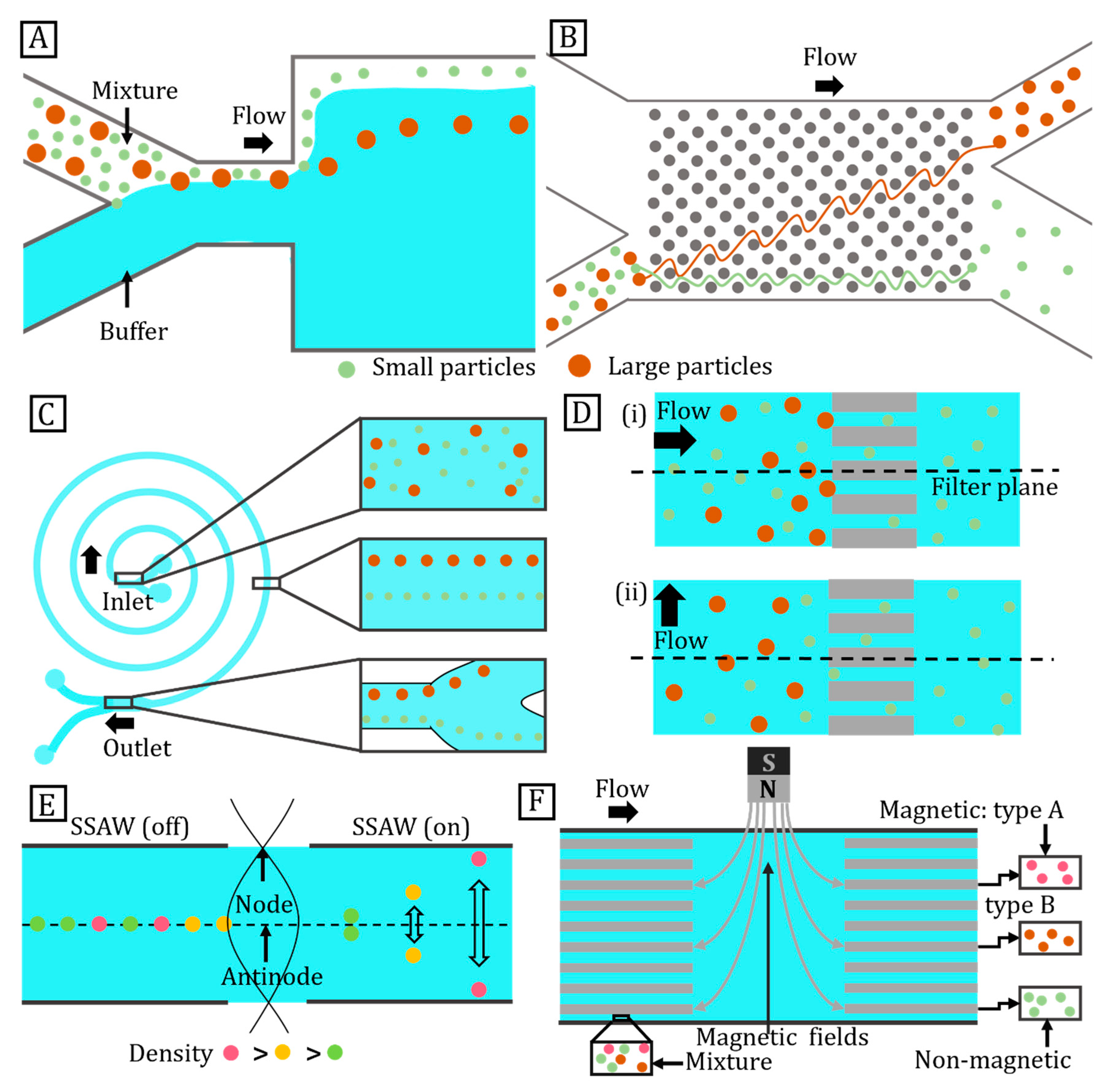
4. Sorting
4.1. Passive Sorting
4.1.1. Pinched Flow Fractionation
4.1.2. Deterministic Lateral Displacement
4.1.3. Inertial Microfluidic Separation
4.1.4. Microfiltration
4.2. Active Method
4.2.1. Acoustic Sorting
4.2.2. Magnetic Field
4.2.3. Electric Field
4.2.4. Light
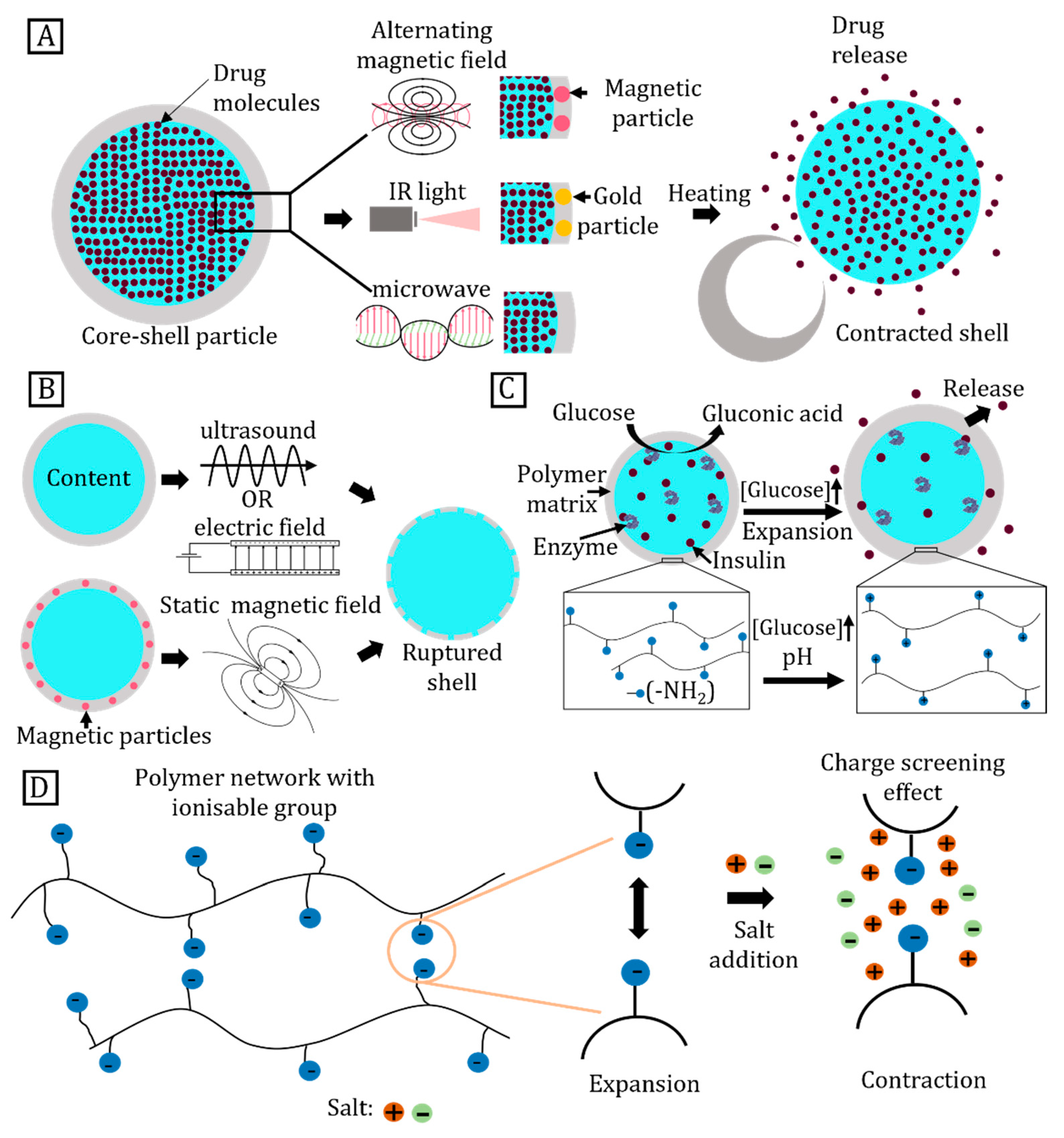
5. Triggered Release
5.1. Thermally Triggered Release
5.1.1. Heating by an Alternating Magnetic Field
5.1.2. Microwave Heating
5.1.3. Infrared Heating
5.2. Physically Triggered Release
5.2.1. Ultrasound
5.2.2. Magnetic Field
5.3. Chemically Triggered Release
5.3.1. pH
5.3.2. Glucose
5.3.3. Enzyme-Responsive Materials
5.3.4. Ionic Strength
6. Conclusions
Author Contributions
Funding
Data Availability Statement
Acknowledgments
Conflicts of Interest
References
- Cao, G.; Wang, Y. Nanostructures and Nanomaterials: Synthesis, Properties, and Applications, 2nd ed.; World Scientific: Singapore, 2011; ISBN 978-981-4322-50-8. [Google Scholar]
- Astruc, D. Nanoparticles and Catalysis; John Wiley & Sons: Hoboken, NJ, USA, 2008; ISBN 978-3-527-62133-0. [Google Scholar]
- Smith, A.M.; Nie, S. Semiconductor Nanocrystals: Structure, Properties, and Band Gap Engineering. Acc. Chem. Res. 2010, 43, 190–200. [Google Scholar] [CrossRef] [Green Version]
- Liu, W.-T. Nanoparticles and Their Biological and Environmental Applications. J. Biosci. Bioeng. 2006, 102, 1–7. [Google Scholar] [CrossRef]
- Xie, X.; Zhang, W.; Abbaspourrad, A.; Ahn, J.; Bader, A.; Bose, S.; Vegas, A.; Lin, J.; Tao, J.; Hang, T.; et al. Microfluidic Fabrication of Colloidal Nanomaterials-Encapsulated Microcapsules for Biomolecular Sensing. Nano Lett. 2017, 17, 2015–2020. [Google Scholar] [CrossRef]
- Nie, H.; Fu, Y.; Wang, C.-H. Paclitaxel and Suramin-Loaded Core/Shell Microspheres in the Treatment of Brain Tumors. Biomaterials 2010, 31, 8732–8740. [Google Scholar] [CrossRef]
- De Jong, W.H.; Borm, P.J. Drug Delivery and Nanoparticles: Applications and Hazards. Int. J. Nanomed. 2008, 3, 133–149. [Google Scholar] [CrossRef] [Green Version]
- Padmanabhan, P.; Kumar, A.; Kumar, S.; Chaudhary, R.K.; Gulyás, B. Nanoparticles in Practice for Molecular-Imaging Applications: An Overview. Acta Biomater. 2016, 41, 1–16. [Google Scholar] [CrossRef]
- Galogahi, F.M.; Zhu, Y.; An, H.; Nguyen, N.-T. Core-Shell Microparticles: Generation Approaches and Applications. J. Sci. Adv. Mater. Devices 2020, 5, 417–435. [Google Scholar] [CrossRef]
- Ju, X.-J.; Chu, L.-Y. Chapter 9—Lab-on-a-Chip Fabrication of Polymeric Microparticles for Drug Encapsulation and Controlled Release. In Microfluidics for Pharmaceutical Applications; Santos, H.A., Liu, D., Zhang, H., Eds.; Micro and Nano Technologies; William Andrew Publishing: Norwich, NY, USA, 2019; pp. 217–280. ISBN 978-0-12-812659-2. [Google Scholar]
- Chong, D.; Liu, X.; Ma, H.; Huang, G.; Han, Y.L.; Cui, X.; Yan, J.; Xu, F. Advances in Fabricating Double-Emulsion Droplets and Their Biomedical Applications. Microfluid. Nanofluid 2015, 19, 1071–1090. [Google Scholar] [CrossRef]
- Masud, M.K.; Umer, M.; Hossain, M.S.A.; Yamauchi, Y.; Nguyen, N.-T.; Shiddiky, M.J.A. Nanoarchitecture Frameworks for Electrochemical MiRNA Detection. Trends Biochem. Sci. 2019, 44, 433–452. [Google Scholar] [CrossRef]
- Hayes, R.; Ahmed, A.; Edge, T.; Zhang, H. Core–Shell Particles: Preparation, Fundamentals and Applications in High Performance Liquid Chromatography. J. Chromatogr. A 2014, 1357, 36–52. [Google Scholar] [CrossRef] [Green Version]
- Sreejith, K.R.; Gorgannezhad, L.; Jin, J.; Ooi, C.H.; Takei, T.; Hayase, G.; Stratton, H.; Lamb, K.; Shiddiky, M.; Dao, D.V.; et al. Core-Shell Beads Made by Composite Liquid Marble Technology as A Versatile Microreactor for Polymerase Chain Reaction. Micromachines 2020, 11, 242. [Google Scholar] [CrossRef] [Green Version]
- Lekshmi, B.S.; Yadav, A.S.; Ranganathan, P.; Varanakkottu, S.N. Simple and Continuous Fabrication of Janus Liquid Marbles with Tunable Particle Coverage Based on Controlled Droplet Impact. Langmuir 2020, 36, 15396–15402. [Google Scholar] [CrossRef] [PubMed]
- Schmaljohann, D. Thermo- and PH-Responsive Polymers in Drug Delivery. Adv. Drug Deliv. Rev. 2006, 58, 1655–1670. [Google Scholar] [CrossRef]
- Sirsi, S.; Borden, M. Microbubble Compositions, Properties and Biomedical Applications. Bubble Sci. Eng. Technol 2009, 1, 3–17. [Google Scholar] [CrossRef] [PubMed] [Green Version]
- Wu, M.; Meng, Q.; Chen, Y.; Zhang, L.; Li, M.; Cai, X.; Li, Y.; Yu, P.; Zhang, L.; Shi, J. Large Pore-Sized Hollow Mesoporous Organosilica for Redox-Responsive Gene Delivery and Synergistic Cancer Chemotherapy. Adv. Mater. 2016, 28, 1963–1969. [Google Scholar] [CrossRef]
- Phan, D.-T.; Shaegh, S.A.M.; Yang, C.; Nguyen, N.-T. Sample Concentration in a Microfluidic Paper-Based Analytical Device Using Ion Concentration Polarization. Sens. Actuators B Chem. 2016, 222, 735–740. [Google Scholar] [CrossRef] [Green Version]
- Fung, W.-T.; Beyzavi, A.; Abgrall, P.; Nguyen, N.-T.; Li, H.-Y. Microfluidic Platform for Controlling the Differentiation of Embryoid Bodies. Lab. Chip 2009, 9, 2591–2595. [Google Scholar] [CrossRef] [PubMed] [Green Version]
- Gorgannezhad, L.; Sreejith, K.R.; Christie, M.; Jin, J.; Ooi, C.H.; Katouli, M.; Stratton, H.; Nguyen, N.-T. Core-Shell Beads as Microreactors for Phylogrouping of E. coli Strains. Micromachines 2020, 11, 761. [Google Scholar] [CrossRef]
- Ji, T.; Lirtsman, V.G.; Avny, Y.; Davidov, D. Preparation, Characterization, and Application of Au-Shell/Polystyrene Beads and Au-Shell/Magnetic Beads. Adv. Mater. 2001, 13, 1253–1256. [Google Scholar] [CrossRef]
- Zhang, X.; Qu, Q.; Zhou, A.; Wang, Y.; Zhang, J.; Xiong, R.; Lenders, V.; Manshian, B.B.; Hua, D.; Soenen, S.J.; et al. Core-Shell Microparticles: From Rational Engineering to Diverse Applications. Adv. Colloid Interface Sci. 2022, 299, 102568. [Google Scholar] [CrossRef]
- Vladisavljević, G.; Al Nuumani, R.; Nabavi, S. Microfluidic Production of Multiple Emulsions. Micromachines 2017, 8, 75. [Google Scholar] [CrossRef]
- Azlinawati Ramli, R.; Ashaier Laftah, W.; Hashim, S. Core–Shell Polymers: A Review. RSC Adv. 2013, 3, 15543–15565. [Google Scholar] [CrossRef]
- Qu, Q.; Zhang, X.; Ravanbakhsh, H.; Tang, G.; Zhang, J.; Deng, Y.; Braeckmans, K.; De Smedt, S.C.; Xiong, R.; Huang, C. Gas-Shearing Synthesis of Core–Shell Multicompartmental Microparticles as Cell-like System for Enzymatic Cascade Reaction. Chem. Eng. J. 2022, 428, 132607. [Google Scholar] [CrossRef]
- Wang, J.-T.; Wang, J.; Han, J.-J. Fabrication of Advanced Particles and Particle-Based Materials Assisted by Droplet-Based Microfluidics. Small 2011, 7, 1728–1754. [Google Scholar] [CrossRef]
- Ghosh Chaudhuri, R.; Paria, S. Core/Shell Nanoparticles: Classes, Properties, Synthesis Mechanisms, Characterization, and Applications. Chem. Rev. 2012, 112, 2373–2433. [Google Scholar] [CrossRef] [PubMed]
- Pu, W.; Fu, D.; Xia, H.; Wang, Z. Preparation of Hollow Polyurethane Microspheres with Tunable Surface Structures via Electrospraying Technology. RSC Adv. 2017, 7, 49828–49837. [Google Scholar] [CrossRef] [Green Version]
- Baranov, D.; Fiore, A.; van Huis, M.; Giannini, C.; Falqui, A.; Lafont, U.; Zandbergen, H.; Zanella, M.; Cingolani, R.; Manna, L. Assembly of Colloidal Semiconductor Nanorods in Solution by Depletion Attraction. Nano Lett. 2010, 10, 743–749. [Google Scholar] [CrossRef]
- Roldughin, V.I. Self-Assembly of Nanoparticles at Interfaces. Russ. Chem. Rev. 2004, 73, 115–145. [Google Scholar] [CrossRef]
- Zhou, J.; Mukherjee, P.; Gao, H.; Luan, Q.; Papautsky, I. Label-Free Microfluidic Sorting of Microparticles. APL Bioeng. 2019, 3, 041504. [Google Scholar] [CrossRef] [Green Version]
- Ukita, Y.; Oguro, T.; Takamura, Y. Density-Gradient-Assisted Centrifugal Microfluidics: An Approach to Continuous-Mode Particle Separation. Biomed. Microdevices 2017, 19, 24. [Google Scholar] [CrossRef]
- Zhang, Y.; Lei, H.; Li, B. Refractive-Index-Based Sorting of Colloidal Particles Using a Subwavelength Optical Fiber in a Static Fluid. Appl. Phys. Express 2013, 6, 072001. [Google Scholar] [CrossRef]
- Uhrich, K.E.; Cannizzaro, S.M.; Langer, R.S.; Shakesheff, K.M. Polymeric Systems for Controlled Drug Release. Chem. Rev. 1999, 99, 3181–3198. [Google Scholar] [CrossRef]
- Commandeur, S.; Van Beusekom, H.M.; Van Der Giessen, W.J. Polymers, Drug Release, and Drug-Eluting Stents. J. Interv. Cardiol. 2006, 19, 500–506. [Google Scholar] [CrossRef]
- Fleige, E.; Quadir, M.A.; Haag, R. Stimuli-Responsive Polymeric Nanocarriers for the Controlled Transport of Active Compounds: Concepts and Applications. Adv. Drug Deliv. Rev. 2012, 64, 866–884. [Google Scholar] [CrossRef]
- Bajpai, A.K.; Shukla, S.K.; Bhanu, S.; Kankane, S. Responsive Polymers in Controlled Drug Delivery. Prog. Polym. Sci. 2008, 33, 1088–1118. [Google Scholar] [CrossRef]
- Jing, Y.; Zhu, Y.; Yang, X.; Shen, J.; Li, C. Ultrasound-Triggered Smart Drug Release from Multifunctional Core−Shell Capsules One-Step Fabricated by Coaxial Electrospray Method. Langmuir 2011, 27, 1175–1180. [Google Scholar] [CrossRef]
- Wang, H.; Yang, L.; Rempel, G.L. Preparation of PH-Responsive Polymer Core–Shell Nanospheres for Delivery of Hydrophobic Antineoplastic Drug Ellipticine. Macromol. Biosci. 2014, 14, 166–172. [Google Scholar] [CrossRef]
- McCoy, C.P.; Brady, C.; Cowley, J.F.; McGlinchey, S.M.; McGoldrick, N.; Kinnear, D.J.; Andrews, G.P.; Jones, D.S. Triggered Drug Delivery from Biomaterials. Expert Opin. Drug Deliv. 2010, 7, 605–616. [Google Scholar] [CrossRef]
- Gu, Z.; Dang, T.T.; Ma, M.; Tang, B.C.; Cheng, H.; Jiang, S.; Dong, Y.; Zhang, Y.; Anderson, D.G. Glucose-Responsive Microgels Integrated with Enzyme Nanocapsules for Closed-Loop Insulin Delivery. ACS Nano 2013, 7, 6758–6766. [Google Scholar] [CrossRef]
- Wei, S.; Wang, Q.; Zhu, J.; Sun, L.; Lin, H.; Guo, Z. Multifunctional Composite Core–Shell Nanoparticles. Nanoscale 2011, 3, 4474–4502. [Google Scholar] [CrossRef]
- Khurshid, H.; Hadjipanayis, C.G.; Chen, H.; Li, W.; Mao, H.; Machaidze, R.; Tzitzios, V.; Hadjipanayis, G.C. Core/Shell Structured Iron/Iron-Oxide Nanoparticles as Excellent MRI Contrast Enhancement Agents. J. Magn. Magn. Mater. 2013, 331, 17–20. [Google Scholar] [CrossRef]
- Menzel, C.; Cambón, A.; Yeates, S.G. Double Emulsion Template Suspension Polymerisation: Towards the Synthesis of Polyelectrolyte Core Porous Hydrophobic Shell Particles for Environmental Applications. J. Mater. Chem. A 2013, 1, 12553–12559. [Google Scholar] [CrossRef]
- Wang, X.; Liu, X.; Huang, X. Bioinspired Protein-Based Assembling: Toward Advanced Life-Like Behaviors. Adv. Mater. 2020, 32, 2001436. [Google Scholar] [CrossRef]
- Augustin, M.A.; Hemar, Y. Nano- and Micro-Structured Assemblies for Encapsulation of Food Ingredients. Chem. Soc. Rev. 2009, 38, 902–912. [Google Scholar] [CrossRef]
- Guiseppi-Elie, A.; Brahim, S.; Narinesingh, D. A Chemically Synthesized Artificial Pancreas: Release of Insulin from Glucose-Responsive Hydrogels. Adv. Mater. 2002, 14, 743–746. [Google Scholar] [CrossRef]
- Tan, H.; Guo, S.; Dinh, N.-D.; Luo, R.; Jin, L.; Chen, C.-H. Heterogeneous Multi-Compartmental Hydrogel Particles as Synthetic Cells for Incompatible Tandem Reactions. Nat. Commun. 2017, 8, 663. [Google Scholar] [CrossRef] [Green Version]
- Pajor-Świerzy, A.; Farraj, Y.; Kamyshny, A.; Magdassi, S. Effect of Carboxylic Acids on Conductivity of Metallic Films Formed by Inks Based on Copper@silver Core-Shell Particles. Colloids Surf. A Physicochem. Eng. Asp. 2017, 522, 320–327. [Google Scholar] [CrossRef]
- Hu, Y.; Zhao, T.; Zhu, P.; Zhu, Y.; Shuai, X.; Liang, X.; Sun, R.; Lu, D.D.; Wong, C.-P. Low Cost and Highly Conductive Elastic Composites for Flexible and Printable Electronics. J. Mater. Chem. C 2016, 4, 5839–5848. [Google Scholar] [CrossRef]
- Fleischmann, E.-K.; Liang, H.-L.; Kapernaum, N.; Giesselmann, F.; Lagerwall, J.; Zentel, R. One-Piece Micropumps from Liquid Crystalline Core-Shell Particles. Nat. Commun. 2012, 3, 1178. [Google Scholar] [CrossRef] [Green Version]
- Campanile, R.; Elia, V.C.; Minopoli, A.; Ud Din Babar, Z.; di Girolamo, R.; Morone, A.; Sakač, N.; Velotta, R.; Della Ventura, B.; Iannotti, V. Magnetic Micromixing for Highly Sensitive Detection of Glyphosate in Tap Water by Colorimetric Immunosensor. Talanta 2023, 253, 123937. [Google Scholar] [CrossRef]
- Zhou, W.; Dong, L.; Sui, X.; Wang, Z.; Zuo, J.; Cai, H.; Chen, Q. High Dielectric Permittivity and Low Loss in PVDF Filled by Core-Shell Zn@ZnO Particles. J. Polym. Res. 2016, 23, 45. [Google Scholar] [CrossRef]
- Wu, W.; Huang, X.; Li, S.; Jiang, P.; Toshikatsu, T. Novel Three-Dimensional Zinc Oxide Superstructures for High Dielectric Constant Polymer Composites Capable of Withstanding High Electric Field. J. Phys. Chem. C 2012, 116, 24887–24895. [Google Scholar] [CrossRef]
- Zhou, W.; Yu, D. Fabrication, Thermal, and Dielectric Properties of Self-Passivated Al/Epoxy Nanocomposites. J. Mater. Sci. 2013, 48, 7960–7968. [Google Scholar] [CrossRef]
- Zhang, Y.; Wang, Y.; Deng, Y.; Li, M.; Bai, J. Enhanced Dielectric Properties of Ferroelectric Polymer Composites Induced by Metal-Semiconductor Zn-ZnO Core–Shell Structure. ACS Appl. Mater. Interfaces 2012, 4, 65–68. [Google Scholar] [CrossRef]
- van der Kooij, R.S.; Steendam, R.; Frijlink, H.W.; Hinrichs, W.L.J. An Overview of the Production Methods for Core–Shell Microspheres for Parenteral Controlled Drug Delivery. Eur. J. Pharm. Biopharm. 2022, 170, 24–42. [Google Scholar] [CrossRef]
- Borra, J.-P. Review on Water Electro-Sprays and Applications of Charged Drops with Focus on the Corona-Assisted Cone-Jet Mode for High Efficiency Air Filtration by Wet Electro-Scrubbing of Aerosols. J. Aerosol Sci. 2018, 125, 208–236. [Google Scholar] [CrossRef]
- Lee, T.H.; Wang, J.; Wang, C.-H. Double-Walled Microspheres for the Sustained Release of a Highly Water Soluble Drug: Characterization and Irradiation Studies. J. Control. Release 2002, 83, 437–452. [Google Scholar] [CrossRef]
- Tan, E.C.; Lin, R.; Wang, C.-H. Fabrication of Double-Walled Microspheres for the Sustained Release of Doxorubicin. J. Colloid Interface Sci. 2005, 291, 135–143. [Google Scholar] [CrossRef]
- Wang, W.; Zhou, S.; Sun, L.; Huang, C. Controlled Delivery of Paracetamol and Protein at Different Stages from Core–Shell Biodegradable Microspheres. Carbohydr. Polym. 2010, 79, 437–444. [Google Scholar] [CrossRef]
- Okubo, M.; Izumi, J. Synthesis of Micron-Sized Monodispersed, Core-Shell Composite Polymer Particles by Seeded Dispersion Polymerization1Presented at the International Symposium on Advanced Technology of Fine Particles, Yokohama, Japan, 12–16 October, 1997. Colloids Surf. A Physicochem. Eng. Asp. 1999, 153, 297–304. [Google Scholar] [CrossRef]
- Zhang, K.; Zheng, L.; Zhang, X.; Chen, X.; Yang, B. Silica-PMMA Core-Shell and Hollow Nanospheres. Colloids Surf. A Physicochem. Eng. Asp. 2006, 277, 145–150. [Google Scholar] [CrossRef]
- Chen, Y.; Zhang, Y.; Li, L.; Hölscher, C. Neuroprotective Effects of Geniposide in the MPTP Mouse Model of Parkinson’s Disease. Eur. J. Pharmacol. 2015, 768, 21–27. [Google Scholar] [CrossRef] [PubMed]
- Ghaffarian, R.; Pérez-Herrero, E.; Oh, H.; Raghavan, S.R.; Muro, S. Chitosan–Alginate Microcapsules Provide Gastric Protection and Intestinal Release of ICAM-1-Targeting Nanocarriers, Enabling GI Targeting In Vivo. Adv. Funct. Mater. 2016, 26, 3382–3393. [Google Scholar] [CrossRef] [PubMed] [Green Version]
- Han, K.; Zhao, Z.; Xiang, Z.; Wang, C.; Zhang, J.; Yang, B. The Sol–Gel Preparation of ZnO/Silica Core–Shell Composites and Hollow Silica Structure. Mater. Lett. 2007, 61, 363–368. [Google Scholar] [CrossRef]
- Zhong, Z.; Yin, Y.; Gates, B.; Xia, Y. Preparation of Mesoscale Hollow Spheres of TiO2 and SnO2 by Templating Against Crystalline Arrays of Polystyrene Beads. Adv. Mater. 2000, 12, 206–209. [Google Scholar] [CrossRef]
- Ye, J.; Van de Broek, B.; De Palma, R.; Libaers, W.; Clays, K.; Van Roy, W.; Borghs, G.; Maes, G. Surface Morphology Changes on Silica-Coated Gold Colloids. Colloids Surf. A Physicochem. Eng. Asp. 2008, 322, 225–233. [Google Scholar] [CrossRef]
- Gao, Y.; Zhao, D.; Chang, M.-W.; Ahmad, Z.; Li, J.-S. Optimising the Shell Thickness-to-Radius Ratio for the Fabrication of Oil-Encapsulated Polymeric Microspheres. Chem. Eng. J. 2016, 284, 963–971. [Google Scholar] [CrossRef]
- Choi, D.H.; Park, C.H.; Kim, I.H.; Chun, H.J.; Park, K.; Han, D.K. Fabrication of Core–Shell Microcapsules Using PLGA and Alginate for Dual Growth Factor Delivery System. J. Control. Release 2010, 147, 193–201. [Google Scholar] [CrossRef]
- Hiep, N.T.; Hai, N.D.; Toi, V.V. Fabrication of Core-Shell PLGA-Chitosan Microparticles Using Electrospinning: Effects of Polymer Concentration. Int. J. Polym. Sci. 2017, 2017, e9580209. [Google Scholar] [CrossRef] [Green Version]
- Dinsmore, A.D.; Hsu, M.F.; Nikolaides, M.G.; Marquez, M.; Bausch, A.R.; Weitz, D.A. Colloidosomes: Selectively Permeable Capsules Composed of Colloidal Particles. Science 2002, 298, 1006–1009. [Google Scholar] [CrossRef] [Green Version]
- Velev, O.D.; Nagayama, K. Assembly of Latex Particles by Using Emulsion Droplets. 3. Reverse (Water in Oil) System. Langmuir 1997, 13, 1856–1859. [Google Scholar] [CrossRef]
- Sheth, T.; Seshadri, S.; Prileszky, T.; Helgeson, M.E. Multiple nanoemulsions. Nat. Reviews. Mater. 2020, 5, 214–228. [Google Scholar] [CrossRef]
- Juttulapa, M.; Piriyaprasarth, S.; Takeuchi, H.; Sriamornsak, P. Effect of High-Pressure Homogenization on Stability of Emulsions Containing Zein and Pectin. Asian J. Pharm. Sci. 2017, 12, 21–27. [Google Scholar] [CrossRef]
- Pekarek, K.J.; Jacob, J.S.; Mathiowitz, E. Double-Walled Polymer Microspheres for Controlled Drug Release. Nature 1994, 367, 258–260. [Google Scholar] [CrossRef]
- Ansary, R.H.; Rahman, M.M.; Awang, M.B.; Katas, H.; Hadi, H.; Mohamed, F.; Doolaanea, A.A.; Kamaruzzaman, Y.B. Preparation, Characterization and in Vitro Release Study of BSA-Loaded Double-Walled Glucose-Poly(Lactide-Co-Glycolide) Microspheres. Arch. Pharm. Res. 2016, 39, 1242–1256. [Google Scholar] [CrossRef]
- Dutta, D.; Fauer, C.; Hickey, K.; Salifu, M.; Stabenfeldt, S.E. Tunable Delayed Controlled Release Profile from Layered Polymeric Microparticles. J. Mater. Chem. B 2017, 5, 4487–4498. [Google Scholar] [CrossRef]
- Huang, H.; Yu, Y.; Hu, Y.; He, X.; Usta, O.B.; Yarmush, M.L. Generation and Manipulation of Hydrogel Microcapsules by Droplet-Based Microfluidics for Mammalian Cell Culture. Lab. Chip 2017, 17, 1913–1932. [Google Scholar] [CrossRef] [PubMed]
- Jenjob, R.; Phakkeeree, T.; Crespy, D. Core–Shell Particles for Drug-Delivery, Bioimaging, Sensing, and Tissue Engineering. Biomater. Sci. 2020, 8, 2756–2770. [Google Scholar] [CrossRef] [PubMed]
- Shah, R.K.; Shum, H.C.; Rowat, A.C.; Lee, D.; Agresti, J.J.; Utada, A.S.; Chu, L.-Y.; Kim, J.-W.; Fernandez-Nieves, A.; Martinez, C.J.; et al. Designer Emulsions Using Microfluidics. Mater. Today 2008, 11, 18–27. [Google Scholar] [CrossRef]
- Kong, T.; Wu, J.; Yeung, K.W.K.; To, M.K.T.; Wang, L. Microfluidic Fabrication of Polymeric Core-Shell Microspheres for Controlled Release Applications. Biomicrofluidics 2013, 7, 044128. [Google Scholar] [CrossRef] [PubMed] [Green Version]
- Tan, S.-H.; Murshed, S.M.S.; Nguyen, N.-T.; Wong, T.N.; Yobas, L. Thermally Controlled Droplet Formation in Flow Focusing Geometry: Formation Regimes and Effect of Nanoparticle Suspension. J. Phys. D Appl. Phys. 2008, 41, 165501. [Google Scholar] [CrossRef] [Green Version]
- Yap, Y.-F.; Tan, S.-H.; Nguyen, N.-T.; Murshed, S.M.S.; Wong, T.-N.; Yobas, L. Thermally Mediated Control of Liquid Microdroplets at a Bifurcation. J. Phys. D Appl. Phys. 2009, 42, 065503. [Google Scholar] [CrossRef]
- Che, Z.; Wong, T.N.; Nguyen, N.-T. A Simple Method for the Formation of Water-in-Oil-in-Water (W/O/W) Double Emulsions. Microfluid. Nanofluid 2017, 21, 8. [Google Scholar] [CrossRef] [Green Version]
- Ekanem, E.E.; Zhang, Z.; Vladisavljević, G.T. Facile Microfluidic Production of Composite Polymer Core-Shell Microcapsules and Crescent-Shaped Microparticles. J. Colloid Interface Sci. 2017, 498, 387–394. [Google Scholar] [CrossRef] [Green Version]
- Armada-Moreira, A.; Taipaleenmäki, E.; Itel, F.; Zhang, Y.; Städler, B. Droplet-Microfluidics towards the Assembly of Advanced Building Blocks in Cell Mimicry. Nanoscale 2016, 8, 19510–19522. [Google Scholar] [CrossRef]
- Beebe, D.J.; Moore, J.S.; Bauer, J.M.; Yu, Q.; Liu, R.H.; Devadoss, C.; Jo, B.-H. Functional Hydrogel Structures for Autonomous Flow Control inside Microfluidic Channels. Nature 2000, 404, 588–590. [Google Scholar] [CrossRef]
- Abate, A.R.; Lee, D.; Do, T.; Holtze, C.; Weitz, D.A. Glass Coating for PDMS Microfluidic Channels by Sol–Gel Methods. Lab. Chip 2008, 8, 516–518. [Google Scholar] [CrossRef]
- Zhou, J.; Ellis, A.V.; Voelcker, N.H. Recent Developments in PDMS Surface Modification for Microfluidic Devices. Electrophoresis 2010, 31, 2–16. [Google Scholar] [CrossRef]
- Sağlam, D.; Venema, P.; de Vries, R.; Sagis, L.M.C.; van der Linden, E. Preparation of High Protein Micro-Particles Using Two-Step Emulsification. Food Hydrocoll. 2011, 25, 1139–1148. [Google Scholar] [CrossRef]
- Kim, S.-H.; Weitz, D.A. One-Step Emulsification of Multiple Concentric Shells with Capillary Microfluidic Devices. Angew. Chem. 2011, 123, 8890–8893. [Google Scholar] [CrossRef]
- Chang, Z.; Serra, C.A.; Bouquey, M.; Prat, L.; Hadziioannou, G. Co-Axial Capillaries Microfluidic Device for Synthesizing Size- and Morphology-Controlled Polymer Core- Polymer Shell Particles. Lab. Chip 2009, 9, 3007–3011. [Google Scholar] [CrossRef]
- Garti, N.; Bisperink, C. Double Emulsions: Progress and Applications. Curr. Opin. Colloid Interface Sci. 1998, 3, 657–667. [Google Scholar] [CrossRef]
- Mu, Y.; Qiu, T.; Li, X. Monodisperse and Multilayer Core–Shell Latex via Surface Cross-Linking Emulsion Polymerization. Mater. Lett. 2009, 63, 1614–1617. [Google Scholar] [CrossRef]
- Chern, C.S. Emulsion Polymerization Mechanisms and Kinetics. Prog. Polym. Sci. 2006, 31, 443–486. [Google Scholar] [CrossRef]
- Pei, X.; Zhai, K.; Tan, Y.; Xu, K.; Lu, C.; Wang, P.; Wang, T.; Chen, C.; Tao, Y.; Dai, L.; et al. Synthesis of Monodisperse Starch-Polystyrene Core-Shell Nanoparticles via Seeded Emulsion Polymerization without Stabilizer. Polymer 2017, 108, 78–86. [Google Scholar] [CrossRef]
- Li, X.; Zuo, J.; Guo, Y.; Yuan, X. Preparation and Characterization of Narrowly Distributed Nanogels with Temperature-Responsive Core and PH-Responsive Shell. Macromolecules 2004, 37, 10042–10046. [Google Scholar] [CrossRef]
- Yao, Z.-C.; Zhang, C.; Ahmad, Z.; Peng, Y.; Chang, M.-W. Microparticle Formation via Tri-Needle Coaxial Electrospray at Stable Jetting Modes. Ind. Eng. Chem. Res. 2020, 59, 14423–14432. [Google Scholar] [CrossRef]
- Suárez, F.J.; Sevilla, M.; Álvarez, S.; Valdés-Solís, T.; Fuertes, A.B. Synthesis of Highly Uniform Mesoporous Sub-Micrometric Capsules of Silicon Oxycarbide and Silica. Chem. Mater. 2007, 19, 3096–3098. [Google Scholar] [CrossRef]
- He, T.; Jokerst, J.V. Structured Micro/Nano Materials Synthesized via Electrospray: A Review. Biomater. Sci. 2020, 8, 5555–5573. [Google Scholar] [CrossRef]
- Rosell-Llompart, J.; Grifoll, J.; Loscertales, I.G. Electrosprays in the Cone-Jet Mode: From Taylor Cone Formation to Spray Development. J. Aerosol Sci. 2018, 125, 2–31. [Google Scholar] [CrossRef]
- Morris, B. The Components of the Wired Spanning Forest Are Recurrent. Probab Theory Relat Fields 2003, 125, 259–265. [Google Scholar] [CrossRef]
- Park, S.; Hwang, S.; Lee, J. PH-Responsive Hydrogels from Moldable Composite Microparticles Prepared by Coaxial Electro-Spray Drying. Chem. Eng. J. 2011, 169, 348–357. [Google Scholar] [CrossRef]
- Bujdák, J. Layer-by-Layer Assemblies Composed of Polycationic Electrolyte, Organic Dyes, and Layered Silicates. J. Phys. Chem. C 2014, 118, 7152–7162. [Google Scholar] [CrossRef]
- Mason, A.F.; Buddingh’, B.C.; Williams, D.S.; van Hest, J.C.M. Hierarchical Self-Assembly of a Copolymer-Stabilized Coacervate Protocell. J. Am. Chem. Soc. 2017, 139, 17309–17312. [Google Scholar] [CrossRef] [Green Version]
- Caruso, R.A.; Susha, A.; Caruso, F. Multilayered Titania, Silica, and Laponite Nanoparticle Coatings on Polystyrene Colloidal Templates and Resulting Inorganic Hollow Spheres. Available online: http://pubs.acs.org/doi/full/10.1021/cm001175a (accessed on 7 March 2022).
- Wang, A.; Zhu, Q.; Xing, Z. Multifunctional Quaternized Chitosan@surface Plasmon Resonance Ag/N-TiO2 Core-Shell Microsphere for Synergistic Adsorption-Photothermal Catalysis Degradation of Low-Temperature Wastewater and Bacteriostasis under Visible Light. Chem. Eng. J. 2020, 393, 124781. [Google Scholar] [CrossRef]
- Yue, Q.; Zhang, Y.; Jiang, Y.; Li, J.; Zhang, H.; Yu, C.; Elzatahry, A.A.; Alghamdi, A.; Deng, Y.; Zhao, D. Nanoengineering of Core–Shell Magnetic Mesoporous Microspheres with Tunable Surface Roughness. J. Am. Chem. Soc. 2017, 139, 4954–4961. [Google Scholar] [CrossRef]
- Jiang, H.; Sang, Y.; Zhang, L.; Liu, M. Self-Assembly and Directed Assembly. In Materials Nanoarchitectonics; John Wiley & Sons Ltd.: Hoboken, NJ, USA, 2018; pp. 165–186. ISBN 978-3-527-80831-1. [Google Scholar]
- Mikkelsen, A.; Kertmen, A.; Khobaib, K.; Rajňák, M.; Kurimský, J.; Rozynek, Z. Assembly of 1D Granular Structures from Sulfonated Polystyrene Microparticles. Materials 2017, 10, 1212. [Google Scholar] [CrossRef] [Green Version]
- Majetich, S.A.; Wen, T.; Booth, R.A. Functional Magnetic Nanoparticle Assemblies: Formation, Collective Behavior, and Future Directions. ACS Nano 2011, 5, 6081–6084. [Google Scholar] [CrossRef] [PubMed]
- Thorkelsson, K.; Bai, P.; Xu, T. Self-Assembly and Applications of Anisotropic Nanomaterials: A Review. Nano Today 2015, 10, 48–66. [Google Scholar] [CrossRef] [Green Version]
- Denkov, N.; Velev, O.; Kralchevski, P.; Ivanov, I.; Yoshimura, H.; Nagayama, K. Mechanism of Formation of Two-Dimensional Crystals from Latex Particles on Substrates. Langmuir 1992, 8, 3183–3190. [Google Scholar] [CrossRef]
- Titov, A.V.; Král, P. Modeling the Self-Assembly of Colloidal Nanorod Superlattices. Nano Lett. 2008, 8, 3605–3612. [Google Scholar] [CrossRef] [PubMed]
- Leekumjorn, S.; Wong, M.S. 5.07—Self-Assembly of Nanoparticle Building Blocks. In Comprehensive Nanoscience and Technology; Andrews, D.L., Scholes, G.D., Wiederrecht, G.P., Eds.; Academic Press: Amsterdam, The Netherlands, 2011; pp. 203–224. ISBN 978-0-12-374396-1. [Google Scholar]
- Ostrovsky, N.; Le Saux, G.; Argaman, U.; Chen, I.; Chen, T.; Chang, C.-H.; Makov, G.; Schvartzman, M. Templated Assembly of Nanoparticles into Continuous Arrays. Langmuir 2021, 37, 9098–9110. [Google Scholar] [CrossRef] [PubMed]
- Velev, O.D.; Furusawa, K.; Nagayama, K. Assembly of Latex Particles by Using Emulsion Droplets as Templates. 1. Microstructured Hollow Spheres. Langmuir 1996, 12, 2374–2384. [Google Scholar] [CrossRef]
- Kralchevsky, P.A.; Nagayama, K. Capillary Forces between Colloidal Particles. Langmuir 1994, 10, 23–36. [Google Scholar] [CrossRef]
- Dimitrov, A.S.; Nagayama, K. Continuous Convective Assembling of Fine Particles into Two-Dimensional Arrays on Solid Surfaces. Langmuir 1996, 12, 1303–1311. [Google Scholar] [CrossRef]
- Yan, Q.; Gao, L.; Sharma, V.; Chiang, Y.-M.; Wong, C.C. Particle and Substrate Charge Effects on Colloidal Self-Assembly in a Sessile Drop. Langmuir 2008, 24, 11518–11522. [Google Scholar] [CrossRef]
- Denkov, N.D.; Velev, O.D.; Kralchevsky, P.A.; Ivanov, I.B.; Yoshimura, H.; Nagayama, K. Two-Dimensional Crystallization. Nature 1993, 361, 26. [Google Scholar] [CrossRef]
- Bigioni, T.P.; Lin, X.-M.; Nguyen, T.T.; Corwin, E.I.; Witten, T.A.; Jaeger, H.M. Kinetically Driven Self Assembly of Highly Ordered Nanoparticle Monolayers. Nat. Mater. 2006, 5, 265–270. [Google Scholar] [CrossRef]
- Lin, Y.; Skaff, H.; Emrick, T.; Dinsmore, A.D.; Russell, T.P. Nanoparticle Assembly and Transport at Liquid-Liquid Interfaces. Science 2003, 299, 226–229. [Google Scholar] [CrossRef] [Green Version]
- Tao, A.R.; Huang, J.; Yang, P. Langmuir−Blodgettry of Nanocrystals and Nanowires. Acc. Chem. Res. 2008, 41, 1662–1673. [Google Scholar] [CrossRef]
- Wang, Z.L.; Harfenist, S.A.; Vezmar, I.; Whetten, R.L.; Bentley, J.; Evans, N.D.; Alexander, K.B. Superlattices of Self-Assembled Tetrahedral Ag Nanocrystals. Adv. Mater. 1998, 10, 808–812. [Google Scholar] [CrossRef]
- Ghosh, S.K.; Böker, A. Self-Assembly of Nanoparticles in 2D and 3D: Recent Advances and Future Trends. Macromol. Chem. Phys. 2019, 220, 1900196. [Google Scholar] [CrossRef] [Green Version]
- Varanakkottu, S.N.; Anyfantakis, M.; Morel, M.; Rudiuk, S.; Baigl, D. Light-Directed Particle Patterning by Evaporative Optical Marangoni Assembly. Nano Lett. 2016, 16, 644–650. [Google Scholar] [CrossRef]
- Xue, X.; Wang, J.; Furlani, E.P. Self-Assembly of Crystalline Structures of Magnetic Core–Shell Nanoparticles for Fabrication of Nanostructured Materials. ACS Appl. Mater. Interfaces 2015, 7, 22515–22524. [Google Scholar] [CrossRef]
- Velev, O.D.; Bhatt, K.H. On-Chip Micromanipulation and Assembly of Colloidal Particles by Electric Fields. Soft Matter 2006, 2, 738–750. [Google Scholar] [CrossRef]
- Sazan, H.; Piperno, S.; Layani, M.; Magdassi, S.; Shpaisman, H. Directed Assembly of Nanoparticles into Continuous Microstructures by Standing Surface Acoustic Waves. J. Colloid Interface Sci. 2019, 536, 701–709. [Google Scholar] [CrossRef]
- Kumar, A.; Chuang, H.-S.; Wereley, S.T. Dynamic Manipulation by Light and Electric Fields: Micrometer Particles to Microliter Droplets. Langmuir 2010, 26, 7656–7660. [Google Scholar] [CrossRef]
- Jiang, L.; Chen, X.; Lu, N.; Chi, L. Spatially Confined Assembly of Nanoparticles. Acc. Chem. Res. 2014, 47, 3009–3017. [Google Scholar] [CrossRef]
- Erb, R.M.; Son, H.S.; Samanta, B.; Rotello, V.M.; Yellen, B.B. Magnetic Assembly of Colloidal Superstructures with Multipole Symmetry. Nature 2009, 457, 999–1002. [Google Scholar] [CrossRef]
- Wang, M.; He, L.; Yin, Y. Magnetic Field Guided Colloidal Assembly. Mater. Today 2013, 16, 110–116. [Google Scholar] [CrossRef]
- Ge, J.; Hu, Y.; Biasini, M.; Beyermann, W.P.; Yin, Y. Superparamagnetic Magnetite Colloidal Nanocrystal Clusters. Angew. Chem. Int. Ed. 2007, 46, 4342–4345. [Google Scholar] [CrossRef] [PubMed]
- He, L.; Hu, Y.; Kim, H.; Ge, J.; Kwon, S.; Yin, Y. Magnetic Assembly of Nonmagnetic Particles into Photonic Crystal Structures. Nano Lett. 2010, 10, 4708–4714. [Google Scholar] [CrossRef] [PubMed]
- Destgeer, G.; Hashmi, A.; Park, J.; Ahmed, H.; Afzal, M.; Jin Sung, H. Microparticle Self-Assembly Induced by Travelling Surface Acoustic Waves. RSC Adv. 2019, 9, 7916–7921. [Google Scholar] [CrossRef] [PubMed] [Green Version]
- Owens, C.E.; Shields, C.W.; Cruz, D.F.; Charbonneau, P.; López, G.P. Highly Parallel Acoustic Assembly of Microparticles into Well-Ordered Colloidal Crystallites. Soft Matter 2016, 12, 717–728. [Google Scholar] [CrossRef] [Green Version]
- Akella, M.; Juárez, J.J. High-Throughput Acoustofluidic Self-Assembly of Colloidal Crystals. ACS Omega 2018, 3, 1425–1436. [Google Scholar] [CrossRef]
- Yang, Y.; Pham, A.T.; Cruz, D.; Reyes, C.; Wiley, B.J.; Lopez, G.P.; Yellen, B.B. Assembly of Colloidal Molecules, Polymers, and Crystals in Acoustic and Magnetic Fields. Adv. Mater. 2015, 27, 4725–4731. [Google Scholar] [CrossRef]
- Yang, Y.; Matsubara, S.; Nogami, M.; Shi, J.; Huang, W. One-Dimensional Self-Assembly of Gold Nanoparticles for Tunable Surface Plasmon Resonance Properties. Nanotechnology 2006, 17, 2821–2827. [Google Scholar] [CrossRef]
- Chen, X.; Lin, L.; Li, Z.; Sun, H.-B. Light-Directed Assembly of Colloidal Matter. Adv. Funct. Mater. 2022, 32, 2104649. [Google Scholar] [CrossRef]
- Farzeena, C.; Varanakkottu, S.N. Patterning of Metallic Nanoparticles over Solid Surfaces from Sessile Droplets by Thermoplasmonically Controlled Liquid Flow. Langmuir 2022, 38, 2003–2013. [Google Scholar] [CrossRef]
- Yamaguchi, K.; Yamamoto, E.; Soma, R.; Nakayama, B.; Kuwahara, M.; Saiki, T. Rapid Assembly of Colloidal Crystals under Laser Illumination on a GeSbTe Substrate. Langmuir 2019, 35, 6403–6408. [Google Scholar] [CrossRef]
- Sajeesh, P.; Sen, A.K. Particle Separation and Sorting in Microfluidic Devices: A Review. Microfluid. Nanofluid 2014, 17, 1–52. [Google Scholar] [CrossRef]
- Chen, G.; Wang, Y.; Tan, L.H.; Yang, M.; Tan, L.S.; Chen, Y.; Chen, H. High-Purity Separation of Gold Nanoparticle Dimers and Trimers. J. Am. Chem. Soc. 2009, 131, 4218–4219. [Google Scholar] [CrossRef] [PubMed]
- Dalili, A.; Samiei, E.; Hoorfar, M. A Review of Sorting, Separation and Isolation of Cells and Microbeads for Biomedical Applications: Microfluidic Approaches. Analyst 2019, 144, 87–113. [Google Scholar] [CrossRef]
- Xi, H.-D.; Zheng, H.; Guo, W.; Gañán-Calvo, A.M.; Ai, Y.; Tsao, C.-W.; Zhou, J.; Li, W.; Huang, Y.; Nguyen, N.-T.; et al. Active Droplet Sorting in Microfluidics: A Review. Lab. Chip 2017, 17, 751–771. [Google Scholar] [CrossRef]
- Shi, J.; Huang, H.; Stratton, Z.; Huang, Y.; Jun Huang, T. Continuous Particle Separation in a Microfluidic Channel via Standing Surface Acoustic Waves (SSAW). Lab. Chip 2009, 9, 3354–3359. [Google Scholar] [CrossRef]
- Yamada, M.; Nakashima, M.; Seki, M. Pinched Flow Fractionation: Continuous Size Separation of Particles Utilizing a Laminar Flow Profile in a Pinched Microchannel. Anal. Chem. 2004, 76, 5465–5471. [Google Scholar] [CrossRef]
- Vig, A.L.; Kristensen, A. Separation Enhancement in Pinched Flow Fractionation. Appl. Phys. Lett. 2008, 93, 203507. [Google Scholar] [CrossRef] [Green Version]
- Morijiri, T.; Sunahiro, S.; Senaha, M.; Yamada, M.; Seki, M. Sedimentation Pinched-Flow Fractionation for Size- and Density-Based Particle Sorting in Microchannels. Microfluid. Nanofluid 2011, 11, 105–110. [Google Scholar] [CrossRef]
- Collins, D.J.; Alan, T.; Neild, A. Particle Separation Using Virtual Deterministic Lateral Displacement (VDLD). Lab. Chip 2014, 14, 1595–1603. [Google Scholar] [CrossRef] [PubMed]
- Bhagat, A.A.S.; Kuntaegowdanahalli, S.S.; Papautsky, I. Continuous Particle Separation in Spiral Microchannels Using Dean Flows and Differential Migration. Lab. Chip 2008, 8, 1906–1914. [Google Scholar] [CrossRef] [PubMed]
- Kuntaegowdanahalli, S.S.; Bhagat, A.A.S.; Kumar, G.; Papautsky, I. Inertial Microfluidics for Continuous Particle Separation in Spiral Microchannels. Lab. Chip 2009, 9, 2973–2980. [Google Scholar] [CrossRef] [PubMed] [Green Version]
- Ji, H.M.; Samper, V.; Chen, Y.; Heng, C.K.; Lim, T.M.; Yobas, L. Silicon-Based Microfilters for Whole Blood Cell Separation. Biomed. Microdevices 2008, 10, 251–257. [Google Scholar] [CrossRef] [PubMed]
- Singh, V.; Purkait, M.K.; Das, C. Cross-Flow Microfiltration of Industrial Oily Wastewater: Experimental and Theoretical Consideration. Sep. Sci. Technol. 2011, 46, 1213–1223. [Google Scholar] [CrossRef]
- Lee, G.-H.; Kim, S.-H.; Ahn, K.; Lee, S.-H.; Park, J.Y. Separation and Sorting of Cells in Microsystems Using Physical Principles. J. Micromech. Microeng. 2015, 26, 013003. [Google Scholar] [CrossRef]
- Jakobsson, O.; Grenvall, C.; Nordin, M.; Evander, M.; Laurell, T. Acoustic Actuated Fluorescence Activated Sorting of Microparticles. Lab. Chip 2014, 14, 1943–1950. [Google Scholar] [CrossRef] [PubMed]
- Munaz, A.; Shiddiky, M.J.A.; Nguyen, N.-T. Recent Advances and Current Challenges in Magnetophoresis Based Micro Magnetofluidics. Biomicrofluidics 2018, 12, 031501. [Google Scholar] [CrossRef]
- Pamme, N.; Eijkel, J.C.T.; Manz, A. On-Chip Free-Flow Magnetophoresis: Separation and Detection of Mixtures of Magnetic Particles in Continuous Flow. J. Magn. Magn. Mater. 2006, 307, 237–244. [Google Scholar] [CrossRef]
- Oksuz, C.; Tekin, H.C. A Vacuum-Integrated Centrifugal Microfluidic Chip for Density-Based Separation of Microparticles. In Proceedings of the 2021 IEEE 34th International Conference on Micro Electro Mechanical Systems (MEMS), Virtual Conference, 25–29 January 2021; pp. 1009–1011. [Google Scholar]
- Ge, S.; Nemiroski, A.; Mirica, K.A.; Mace, C.R.; Hennek, J.W.; Kumar, A.A.; Whitesides, G.M. Magnetic Levitation in Chemistry, Materials Science, and Biochemistry. Angew. Chem. Int. Ed. 2020, 59, 17810–17855. [Google Scholar] [CrossRef]
- Patel, S.; Qian, S.; Xuan, X. Reservoir-Based Dielectrophoresis for Microfluidic Particle Separation by Charge. Electrophoresis 2013, 34, 961–968. [Google Scholar] [CrossRef] [PubMed]
- Zhu, J.; Canter, R.C.; Keten, G.; Vedantam, P.; Tzeng, T.-R.J.; Xuan, X. Continuous-Flow Particle and Cell Separations in a Serpentine Microchannel via Curvature-Induced Dielectrophoresis. Microfluid. Nanofluid 2011, 11, 743–752. [Google Scholar] [CrossRef]
- Sun, H.; Ren, Y.; Hou, L.; Tao, Y.; Liu, W.; Jiang, T.; Jiang, H. Continuous Particle Trapping, Switching, and Sorting Utilizing a Combination of Dielectrophoresis and Alternating Current Electrothermal Flow. Anal. Chem. 2019, 91, 5729–5738. [Google Scholar] [CrossRef] [PubMed]
- Gascoyne, P.R.C.; Vykoukal, J. Particle Separation by Dielectrophoresis. Electrophoresis 2002, 23, 1973–1983. [Google Scholar] [CrossRef] [PubMed]
- Atajanov, A.; Zhbanov, A.; Yang, S. Sorting and Manipulation of Biological Cells and the Prospects for Using Optical Forces. Micro Nano Syst. Lett. 2018, 6, 2. [Google Scholar] [CrossRef] [Green Version]
- MacDonald, M.P.; Spalding, G.C.; Dholakia, K. Microfluidic Sorting in an Optical Lattice. Nature 2003, 426, 421–424. [Google Scholar] [CrossRef] [PubMed]
- Jonáš, A.; Zemánek, P. Light at Work: The Use of Optical Forces for Particle Manipulation, Sorting, and Analysis. Electrophoresis 2008, 29, 4813–4851. [Google Scholar] [CrossRef] [PubMed]
- Dibbern, E.M.; Toublan, F.J.-J.; Suslick, K.S. Formation and Characterization of Polyglutamate Core−Shell Microspheres. J. Am. Chem. Soc. 2006, 128, 6540–6541. [Google Scholar] [CrossRef] [PubMed] [Green Version]
- Pradhan, P.; Giri, J.; Rieken, F.; Koch, C.; Mykhaylyk, O.; Döblinger, M.; Banerjee, R.; Bahadur, D.; Plank, C. Targeted Temperature Sensitive Magnetic Liposomes for Thermo-Chemotherapy. J. Control. Release 2010, 142, 108–121. [Google Scholar] [CrossRef]
- Shi, Y.; Ma, C.; Du, Y.; Yu, G. Microwave-Responsive Polymeric Core–Shell Microcarriers for High-Efficiency Controlled Drug Release. J. Mater. Chem. B 2017, 5, 3541–3549. [Google Scholar] [CrossRef] [PubMed]
- Begum, R.; Farooqi, Z.H.; Khan, S.R. Poly(N-Isopropylacrylamide-Acrylic Acid) Copolymer Microgels for Various Applications: A Review. Int. J. Polym. Mater. Polym. Biomater. 2016, 65, 841–852. [Google Scholar] [CrossRef]
- Idziak, I.; Avoce, D.; Lessard, D.; Gravel, D.; Zhu, X.X. Thermosensitivity of Aqueous Solutions of Poly(N,N-Diethylacrylamide). Macromolecules 1999, 32, 1260–1263. [Google Scholar] [CrossRef]
- Horne, R.A.; Almeida, J.P.; Day, A.F.; Yu, N.-T. Macromolecule Hydration and the Effect of Solutes on the Cloud Point of Aqueous Solutions of Polyvinyl Methyl Ether: A Possible Model for Protein Denaturation and Temperature Control in Homeothermic Animals. J. Colloid Interface Sci. 1971, 35, 77–84. [Google Scholar] [CrossRef]
- Van Durme, K.; Verbrugghe, S.; Du Prez, F.E.; Van Mele, B. Influence of Poly(Ethylene Oxide) Grafts on Kinetics of LCST Behavior in Aqueous Poly(N-Vinylcaprolactam) Solutions and Networks Studied by Modulated Temperature DSC. Macromolecules 2004, 37, 1054–1061. [Google Scholar] [CrossRef]
- Hoogenboom, R. 2—Temperature-Responsive Polymers: Properties, Synthesis and Applications. In Smart Polymers and Their Applications; Aguilar, M.R., San Román, J., Eds.; Woodhead Publishing: Sawston, UK, 2014; pp. 15–44. ISBN 978-0-85709-695-1. [Google Scholar]
- Wang, Y.; Kohane, D.S. External Triggering and Triggered Targeting Strategies for Drug Delivery. Nat. Rev. Mater. 2017, 2, 17020. [Google Scholar] [CrossRef]
- Dennis, C.L.; Ivkov, R. Physics of Heat Generation Using Magnetic Nanoparticles for Hyperthermia. Int. J. Hyperth. 2013, 29, 715–729. [Google Scholar] [CrossRef] [PubMed]
- Rosensweig, R.E. Heating Magnetic Fluid with Alternating Magnetic Field. J. Magn. Magn. Mater. 2002, 252, 370–374. [Google Scholar] [CrossRef]
- Svoboda, J. Magnetic Separation. In Encyclopedia of Materials: Science and Technology; Buschow, K.H.J., Cahn, R.W., Flemings, M.C., Ilschner, B., Kramer, E.J., Mahajan, S., Veyssière, P., Eds.; Elsevier: Oxford, UK, 2005; pp. 1–7. ISBN 978-0-08-043152-9. [Google Scholar]
- Liu, X.; Zhang, Y.; Wang, Y.; Zhu, W.; Li, G.; Ma, X.; Zhang, Y.; Chen, S.; Tiwari, S.; Shi, K.; et al. Comprehensive Understanding of Magnetic Hyperthermia for Improving Antitumor Therapeutic Efficacy. Theranostics 2020, 10, 3793–3815. [Google Scholar] [CrossRef]
- Horikoshi, S.; Schiffmann, R.F.; Fukushima, J.; Serpone, N. Physics of Microwave Heating. In Microwave Chemical and Materials Processing: A Tutorial; Horikoshi, S., Schiffmann, R.F., Fukushima, J., Serpone, N., Eds.; Springer: Singapore, 2018; pp. 87–143. ISBN 978-981-10-6466-1. [Google Scholar]
- Qiu, H.; Cui, B.; Li, G.; Yang, J.; Peng, H.; Wang, Y.; Li, N.; Gao, R.; Chang, Z.; Wang, Y. Novel Fe3O4@ZnO@mSiO2 Nanocarrier for Targeted Drug Delivery and Controllable Release with Microwave Irradiation. J. Phys. Chem. C 2014, 118, 14929–14937. [Google Scholar] [CrossRef]
- Cheng, P.; Ding, Z.; Yuan, H.; Zheng, D.; An, P.; Wang, Z.; Zhao, H.; Bao, J. Probing SPR Heating of Metal Nanostructures Coated on Fiber Based Plasmonic Sensor. Chem. Phys. Lett. 2020, 738, 136869. [Google Scholar] [CrossRef]
- Galvez, F.; Pérez de Lara, D.; Spottorno, J.; García, M.A.; Vicent, J.L. Heating Effects of Low Power Surface Plasmon Resonance Sensors. Sens. Actuators B Chem. 2017, 243, 806–811. [Google Scholar] [CrossRef]
- Kooiman, K.; Böhmer, M.R.; Emmer, M.; Vos, H.J.; Chlon, C.; Shi, W.T.; Hall, C.S.; de Winter, S.H.P.M.; Schroën, K.; Versluis, M.; et al. Oil-Filled Polymer Microcapsules for Ultrasound-Mediated Delivery of Lipophilic Drugs. J. Control. Release 2009, 133, 109–118. [Google Scholar] [CrossRef]
- Sirsi, S.R.; Borden, M.A. State-of-the-Art Materials for Ultrasound-Triggered Drug Delivery. Adv. Drug Deliv. Rev. 2014, 72, 3–14. [Google Scholar] [CrossRef] [Green Version]
- Gupta, P.; Vermani, K.; Garg, S. Hydrogels: From Controlled Release to PH-Responsive Drug Delivery. Drug Discov. Today 2002, 7, 569–579. [Google Scholar] [CrossRef] [PubMed]
- Katchalsky, A. Rapid Swelling and Deswelling of Reversible Gels of Polymeric Acids by Ionization. Experientia 1949, 5, 319–320. [Google Scholar] [CrossRef] [PubMed]
- Podual, K.; Doyle, F.J.; Peppas, N.A. Preparation and Dynamic Response of Cationic Copolymer Hydrogels Containing Glucose Oxidase. Polymer 2000, 41, 3975–3983. [Google Scholar] [CrossRef]
- Roy, D.; Cambre, J.N.; Sumerlin, B.S. Future Perspectives and Recent Advances in Stimuli-Responsive Materials. Prog. Polym. Sci. 2010, 35, 278–301. [Google Scholar] [CrossRef]
- Toledano, S.; Williams, R.J.; Jayawarna, V.; Ulijn, R.V. Enzyme-Triggered Self-Assembly of Peptide Hydrogels via Reversed Hydrolysis. J. Am. Chem. Soc. 2006, 128, 1070–1071. [Google Scholar] [CrossRef]
- Ulijn, R.V. Enzyme-Responsive Materials: A New Class of Smart Biomaterials. J. Mater. Chem. 2006, 16, 2217–2225. [Google Scholar] [CrossRef]
- Lv, B.; Wei, M.; Liu, Y.; Liu, X.; Wei, W.; Liu, S. Ultrasensitive Photometric and Visual Determination of Organophosphorus Pesticides Based on the Inhibition of Enzyme-Triggered Formation of Core-Shell Gold-Silver Nanoparticles. Microchim. Acta 2016, 183, 2941–2948. [Google Scholar] [CrossRef]
- Sampath Udeni Gunathilake, T.M.; Ching, Y.C.; Chuah, C.H.; Rahman, N.A.; Liou, N.-S. Recent Advances in Celluloses and Their Hybrids for Stimuli-Responsive Drug Delivery. Int. J. Biol. Macromol. 2020, 158, 670–688. [Google Scholar] [CrossRef]
- Jacob, D.S.; Genish, I.; Klein, L.; Gedanken, A. Carbon-Coated Core Shell Structured Copper and Nickel Nanoparticles Synthesized in an Ionic Liquid. J. Phys. Chem. B 2006, 110, 17711–17714. [Google Scholar] [CrossRef]
- Wen, X.; Bao, D.; Chen, M.; Zhang, A.; Liu, C.; Sun, R. Preparation of CMC/HEC Crosslinked Hydrogels for Drug Delivery. BioResources 2015, 10, 8339–8351. [Google Scholar] [CrossRef] [Green Version]
- García, M.C. 14—Ionic-Strength-Responsive Polymers for Drug Delivery Applications. In Stimuli Responsive Polymeric Nanocarriers for Drug Delivery Applications; Makhlouf, A.S.H., Abu-Thabit, N.Y., Eds.; Woodhead Publishing Series in Biomaterials; Woodhead Publishing: Sawston, UK, 2019; pp. 393–409. ISBN 978-0-08-101995-5. [Google Scholar]


| Fabrication Method | Materials: Shell/Core | Particle Size (µm) | Dispersity | Encapsulation Efficiency |
|---|---|---|---|---|
| Emulsification | 45–350 | Monodisperse (coefficient of variation, COV < 10%) | High (90–100%) | |
| Polymerisation | 0.2–10 | Polydisperse (COV = 20–50%) | High (>80%) | |
| Gas-shearing | 20–250 | Monodisperse (COV < 8%) | Low (30–70%) | |
| Sol–gel | 0.1–0.4 | Polydisperse (COV 40–60%) | High (80–100%) | |
| Electrospray | 0.2–100 | Polydisperse (COV = 5–40%) | High (65–100%) | |
| Self-assembly | 800–5000 | Polydisperse (COV = 40–70%) | Low (<50%) |
Disclaimer/Publisher’s Note: The statements, opinions and data contained in all publications are solely those of the individual author(s) and contributor(s) and not of MDPI and/or the editor(s). MDPI and/or the editor(s) disclaim responsibility for any injury to people or property resulting from any ideas, methods, instructions or products referred to in the content. |
© 2023 by the authors. Licensee MDPI, Basel, Switzerland. This article is an open access article distributed under the terms and conditions of the Creative Commons Attribution (CC BY) license (https://creativecommons.org/licenses/by/4.0/).
Share and Cite
Yadav, A.S.; Tran, D.T.; Teo, A.J.T.; Dai, Y.; Galogahi, F.M.; Ooi, C.H.; Nguyen, N.-T. Core–Shell Particles: From Fabrication Methods to Diverse Manipulation Techniques. Micromachines 2023, 14, 497. https://doi.org/10.3390/mi14030497
Yadav AS, Tran DT, Teo AJT, Dai Y, Galogahi FM, Ooi CH, Nguyen N-T. Core–Shell Particles: From Fabrication Methods to Diverse Manipulation Techniques. Micromachines. 2023; 14(3):497. https://doi.org/10.3390/mi14030497
Chicago/Turabian StyleYadav, Ajeet Singh, Du Tuan Tran, Adrian J. T. Teo, Yuchen Dai, Fariba Malekpour Galogahi, Chin Hong Ooi, and Nam-Trung Nguyen. 2023. "Core–Shell Particles: From Fabrication Methods to Diverse Manipulation Techniques" Micromachines 14, no. 3: 497. https://doi.org/10.3390/mi14030497