Article

A Novel Multi-Modal Teleoperation of a Humanoid Assistive Robot with Real-Time Motion Mimic

1
Mechatronics Engineering, Universidad Nacional de Colombia, Cra 45, Bogatá 111321, Colombia
2
Computer Science, University of Wisconsin Milwaukee, Milwaukee, WI 53212, USA
3
Electrical Engineering, College Ahuntsic, Montreal, QC 9155, Canada
4
Electrical Engineering, University of Sharjah, University City, Sharjah 27272, United Arab Emirates
5
Biorobotics Laboratory, Mechanical Engineering, University of Wisconsin Milwaukee, Milwaukee, WI 53212, USA
*
Author to whom correspondence should be addressed.
Micromachines 2023, 14(2), 461; https://doi.org/10.3390/mi14020461
Submission received: 31 December 2022 / Revised: 10 February 2023 / Accepted: 11 February 2023 / Published: 16 February 2023
(This article belongs to the Special Issue Assistive Robots)

Abstract

:
This research shows the development of a teleoperation system with an assistive robot (NAO) through a Kinect V2 sensor, a set of Meta Quest virtual reality glasses, and Nintendo Switch controllers (Joycons), with the use of the Robot Operating System (ROS) framework to implement the communication between devices. In this paper, two interchangeable operating models are proposed. An exclusive controller is used to control the robot’s movement to perform assignments that require long-distance travel. Another teleoperation protocol uses the skeleton joints information readings by the Kinect sensor, the orientation of the Meta Quest, and the button press and thumbstick movements of the Joycons to control the arm joints and head of the assistive robot, and its movement in a limited area. They give image feedback to the operator in the VR glasses in a first-person perspective and retrieve the user’s voice to be spoken by the assistive robot. Results are promising and can be used for educational and therapeutic purposes.

1. Introduction

Human–robot interactions have been one of the most studied fields in robotics during the last decade, having great technological developments in areas such as the teleoperation of machines, which has allowed humankind to reach places and perform tasks that were previously considered impossible in a comfortable and safe way [1,2,3]. In addition, with the introduction of assistive humanoid robots to the market, a new spectrum for teleoperation has been generated, having a great focus on this type of machine, as they can have great potential in educational or even therapeutic fields [4,5,6,7,8,9].
One of the most common assistive humanoid robots used to achieve this goal is the NAO robot, having an advanced high-level programming interface (choreography) that can be easily introduced to people with no programming skills [10]. However, when the robot must perform more human-like movements, there are two methods to do: by giving it a series of steps to accomplish the duty, which take a long time and increases its difficulty and complexity, or by using sensors to track and retrieve the human motion to be performed by the robot. This last option has more advantages; it allows the human operator to directly manipulate the robot, increasing their decision making and adaptability in any given task.
Many approaches have been made in research and developments on imitation-based systems with the NAO robot, introducing many sensing devices that can track human motion in real-time as the mXsens MVN full-body motion capturer [11] or the MoCap [12]. However, these devices are costly and not very affordable, so most of the real-time teleoperation work has been conducted using depth cameras, such as the Kinect [13,14,15] as it is very cost-effective. Nevertheless, some of these systems are stationary and with minimal focus on mobility and other teleoperation systems, which can be done with direct visual contact on the robot without considering an immersive experience for the operator.
This work proposes a teleoperation concept in an ROS environment with two different modalities of use that can be changed with a Joycon controller. One is used to teleoperate the assistive robot with the Joycon’s gamepad for long-distance tasks. The other is used for short-distance tasks, which, in addition to upper body imitation, would enable the operator to walk and turn in a specific, close area in real time. The goal is accomplished by using a Kinect sensor V2 to track the traveling movements of the operator’s arms, and the motion of both their shoulder and elbow joints to be sent to the robot. At the same time, the Joycons will control both the wrist joints and hands. Furthermore, to achieve an immersive experience, it is connected to a Meta Quest to retrieve the camera image of the robot and control its head joints and the use of the Kinect microphone to speak through the robot. The inverse kinematic used in the research is an innovative approach inspired by natural motion and can imitate natural human movement. This integrated system can be used for academic purposes. However, it could potentially be used in occupational therapy, carrying out interactive therapy sessions with children who have a disorder on the autistic spectrum. With the therapists using this system to teleoperate with the assistive robot, they will interact with the patients through NAO, which could be more comfortable for the children and improve their communication skills.

2. State of the Art

There have been many approaches to teleoperate the assistive robot NAO using different sensors to acquire human skeleton movement data [11,12,14,15,16,17,18,19].
Stanton, Bogdanovych, and Ratanasena present and evaluate a method for teleoperating an assistive humanoid robot via a full-body motion capture suit, called “mXsens MVN full-body motion capturer”, tracking each joint of each limb separately through motion sensors embedded in the suit in [11]. Nuñez, Dajles, and Siles, in [12], use markers displayed all over the human operator to track body motion captured by a MoCap with cameras of the series Prime 41 from OptiTrack.
However, plenty of teleoperation developments have been conducted with Kinect sensors [17], which are low-cost and easy to find in the market. Mota, Moreira, and Pereira do Nascimento [18] use the Kinect to track the upper limbs of the operator to be mapped in the NAO Robot. Li et al. [20] take a similar approach to teleoperating the assistive robot by tracking the superior limbs of the operator and solving the inverse kinematics of the robot limbs. Mukherjee, Paramkusam, and Dwivedy [19] take three different approaches to solve the arm kinematics of the operator to be used in the robot arms. The first one is a geometrical approach, the second one is by solving Inverse kinematics using adaptive neuro-fuzzy inference systems (ANFIS), and the third one is by resolving the inverse kinematics using the iterative Jacobian method. Nevertheless, all of these researches focused on the movement of the limb as just stationary. For this reason, developments have included interactive poses with the Kinect sensor to control the assistive robot’s movements in the work area. Rodriguez et al. developed a software package that allows real-time speech-based guidance and gesture-based teleoperation in [15]. Almetwally and Mallem [14] used leg and arm gestures to interact with the teleoperation system, which allow navigation of the robot in a close area.
After analyzing these developed platforms, it can be seen that plenty of the approaches have been made almost exclusively with Windows software since there is convenience in finding the device drivers in this platform. Many researchers have used Linux software to connect the sensor devices and the robot by ROS, which has the great advantage of a messaging system that uses communication between distributed nodes via the anonymous publish/subscribe mechanism resulting in better connectivity between devices [21], even though these have to be used with third-party drivers created by the Linux programmer community [22]. Avalos et al. [13] develop a method to teleoperate the NAO robot using ROS and Naoqi bridges, although using other Windows computers to handle the data acquisition of the Kinect sensor. Ajili, Mallem, and Didier in [23] use a gesture recognition system based on the Hidden Markov Model method to teleoperate NAO. Ref. [14,15] also develop their research in an ROS environment, using the free source package to interact with the robot NAO.
It is also worth noting the investigations of Sripada et al. [24], which propose a teleoperation concept with upper body imitation that would enable users to walk forward or backward, and also turn the humanoid robot with 20 DoF (Degree of Freedom) in real-time. Fritsche et al.  [25] provide a first-person teleoperation framework for humanoid robots using a system based on Kinect, Meta Quest, and SensorGlove to an iCub robot.
In this work, an approach that integrates the aforementioned study’s strengths is proposed by providing a first-person teleoperation framework for the assistive robot NAO through a real-time teleoperating system based on Kinect sensor V2, Meta Quest, and Joycon controllers in an ROS ecosystem. It allows the operator to change between two modalities to control the assistive robot’s long and short-distance tasks. Controlling the robot’s movement and orientation with the Joycons in the first modality, and controlling the arms, head, whole body position, and orientation in the other modality, where the operator can see through the robot head camera and speak via the microphone.

3. Preliminaries

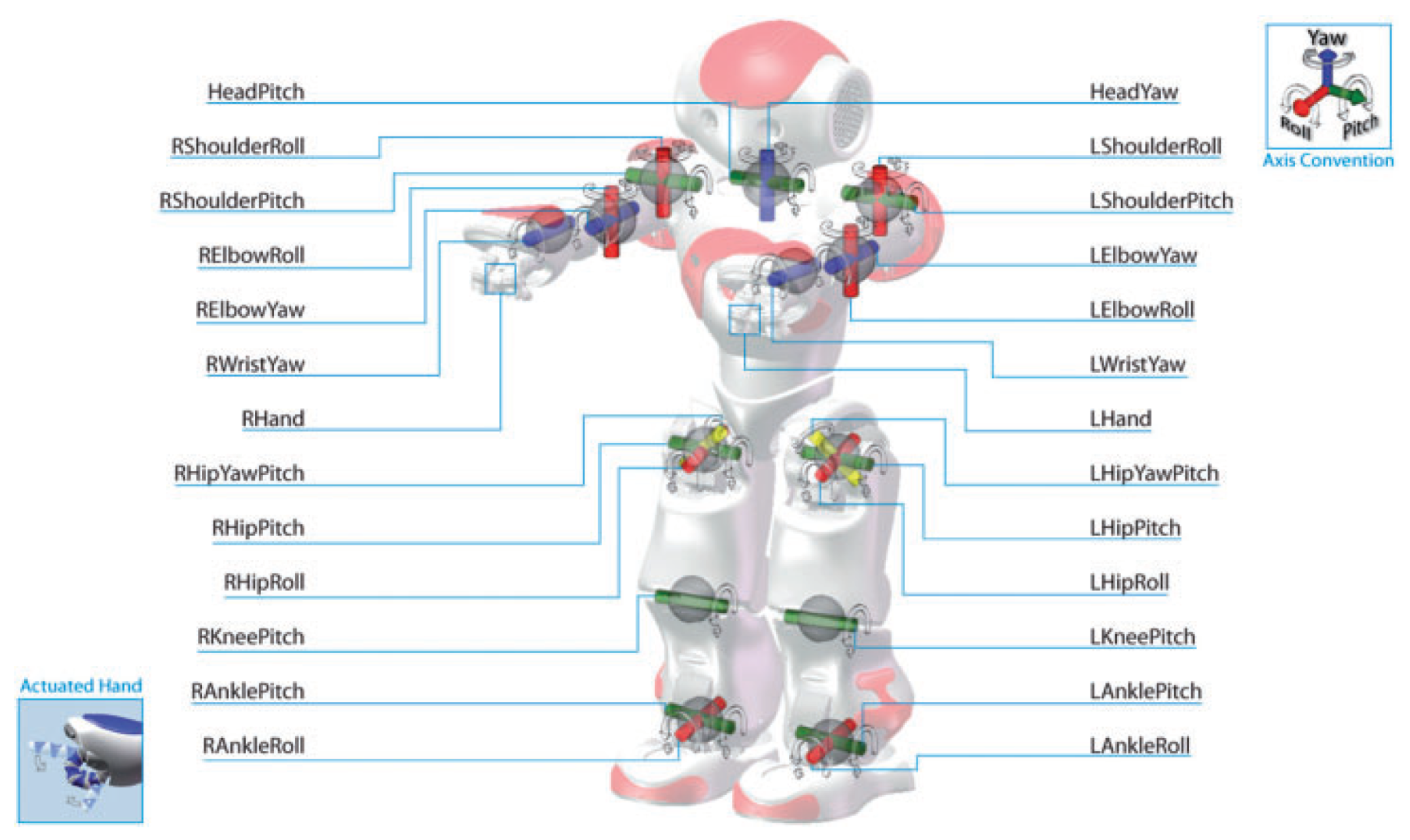
3.1. Humanoid Assistive Robot

The NAO robot from SoftBank Robotics was chosen to achieve the teleoperation task with an assistive robot [26]. With 25 degrees of freedom (DOF), NAO is 4.5 kg in weight and 573.2 mm in height, making it the lightest and smallest robot in the Aldebaran catalog. As an educational robot, for its main purpose, NAO can perform a series of tasks from image retrieving and analysis to walking and moving toward goal points and speech recognition. This robot can be programmed by the Choreagraphe suite or with the Naoqi SDK, which is available in different programming languages, such as Python or C++ [27]. All the joints of the NAO robot are depicted in Figure 1, and all the sensors are indicated in Figure 2.

3.2. Robot Operating System (ROS)

The Robot Operating System, commonly known as ROS, is a framework for robot software development. The system is based on a modular concept. Modules are named nodes in ROS, and nodes communicate via topics, services, or actions following an asynchronous publisher/subscriber protocol. In addition, ROS gives the advantage of working in different languages, such as python or C++, and performs a reliable connection between them [30]. A typical ROS model and it’s components are illustrated in Figure 3.

3.3. Kinect Sensor

To retrieve motion body data of the operator, the Microsoft Kinect V2 [31] was used. It combines a camera and a depth sensor to capture depth, color, and IR images to retrieve 3D object data. Both the color and depth image are transformed into a common frame, with the origin located at the center of the sensor, called Camera Space [32]. These devices are commonly used for body tracking and are more affordable compared to full body tracking suites. Nonetheless, this kind of sensor has two disadvantages. First, data acquisition is noisy and has to be treated before it is used in tasks with precision requirements. Second, by relying on the sensor’s field of vision, the data acquired depends on the tracking of the body that is not occluded by other objects or even by other parts of the body. By working in a Linux environment, there is often official support with drivers of devices such as the Kinect sensor or the Meta Quest, which usually worked with just Windows platforms or their game console device. To work with the Kinect, finding a third-party driver is necessary that can retrieve depth images and allow human body recognition with this sensor. OpenNI2 (Open Natural Interaction) is an open-source software development kit for the RGB-D sensor as the Kinect sensor or the PrimeSense camera [33]. In addition, NiTE2 is a middleware, which has features such as human detection, posture estimation, hand tracking, and gesture detection. For this project, it is used to achieve the Cartesian coordinates of 15 identifiable joints [34]. Furthermore, it was used with the python bindings because it is easier to program in the ROS environment, which was coded in python in its majority. An example of human body tracking is shown in Figure 4.

3.4. Meta Quest

To achieve a first-person immersive teleoperation experience, a Meta Quest was used. It is a virtual reality headset created by Meta [35]. It uses a combination of three-axis gyros, accelerometers, and magnetometers, which make it capable of absolute (relative to Earth) head orientation tracking without drift. The gyroscope data are retrieved in quaternions, which are transformed into Euler angles to move the head joints. Due to the unavailability of SDK in Linux, OpenHMD drivers are implemented. They provide a Free and Open Source API for immersive technology [36]. It supports a wide range of devices, such as the Meta Quest. It is used with the python bindings by Lubosz Sarnecki to retrieve the device’s orientation and use its display in extended mode (as a second display for the computer) [36].

4. Control Architecture and Theoretical Analysis

The control structure of the software implementation and its architecture is depicted in Figure 5. The blue lines represent data provided by the operator to control the robot’s motion. In contrast, the red lines represent the data provided by the NAO to have a visual confirmation of the robot movements from a first-person perspective. As observed, the three devices had independent communication with the robot, allowing it to divide the teleoperation process in parallel actions that control each of them as part of the robot.
The control of the robot is made by the use of the controls to interact with a Human Machine Interface (HMI) to select one of the two teleoperation modalities, which can be seen in the Algorithm 1, which are explained in more detail in the next subsection.
Algorithm 1: Main menu of the teleoperation system
1:procedureROS NAO Node(Nodes and Topics)
2:Create ROS NAO Node
3:Create ROS Topic Subscriber to Kinect topic;
4:Create ROS Topic Subscriber to Meta Quest topic;
5:Create ROS Topic Subscriber to left Joycon topic;
6:Create ROS Topic Subscriber to the right Joycon topic;
7: for ROS NAO node exist do
8:  Print “Welcome to the NAO teleoperation system”
9:  Print “Press “START” to continue”
10:  if Joycon “START” button is pressed then
11:   if Joycon “X” button is pressed then
12:    Enter Joycon teleoperation mode;
13:    if Joycon “B” button is pressed then
14:     break;
15:    end if
16:   end if
17:  end if
18:  if Joycon “A” button is pressed then
19:   Enter Full teleoperation mode;
20:   if Joycon “B” button is pressed then
21:    break;
22:   end if
23:  end if
24: end if
25: Destroy ROS NAO Node;
26: Destroy ROS Topic Subscriber to Kinect topic;
27: Destroy ROS Topic Subscriber to Meta Quest topic;
28: Destroy ROS Topic Subscriber to left Joycon topic;
29: Destroy ROS Topic Subscriber to the right Joycon topic;
30:end procedure

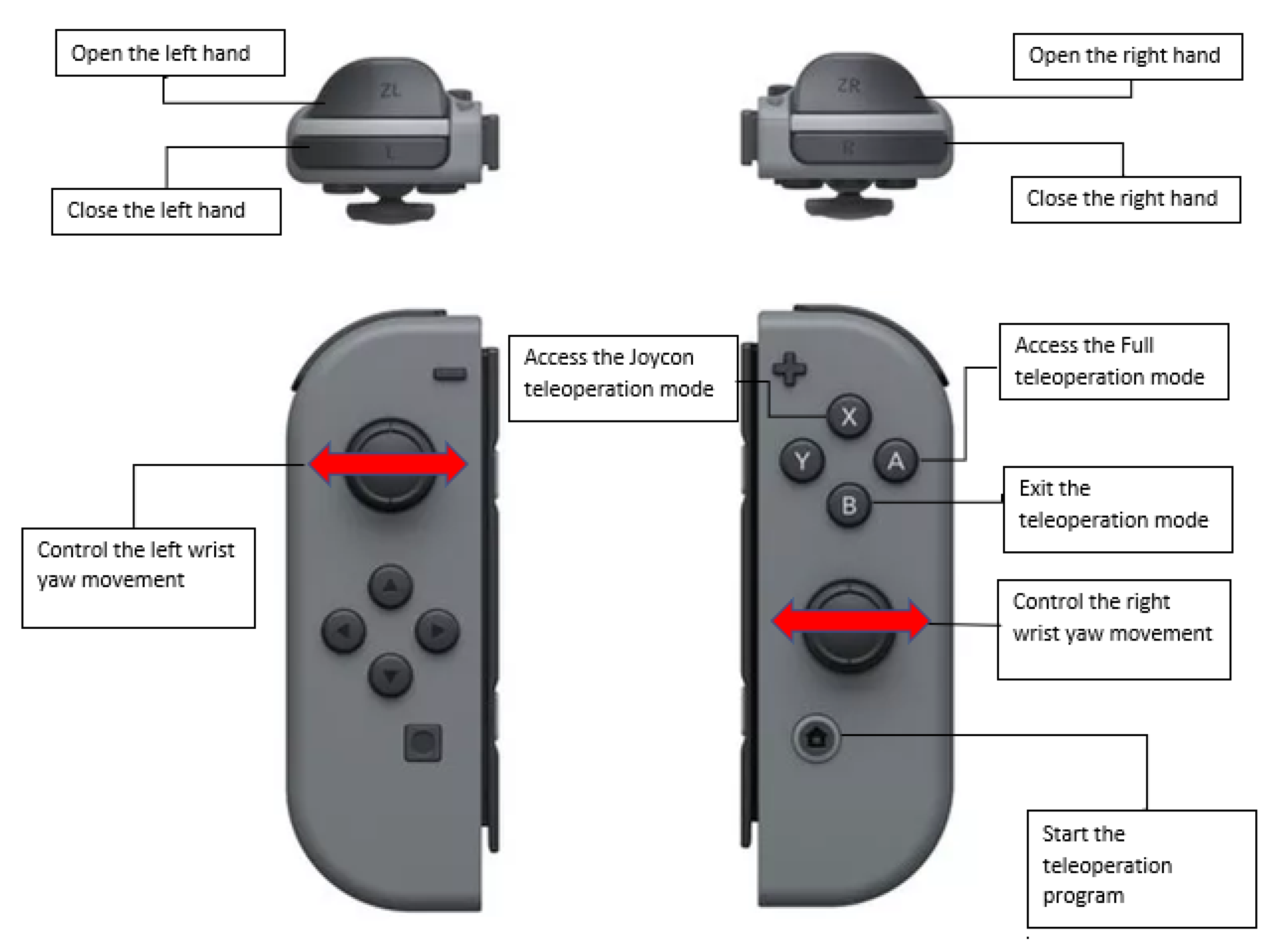
4.1. Joycon Teleoperation Mode

The first mode of teleoperation aims to move the robot from one distance to another in the easiest way possible for the operator. In this mode, the user only has to manipulate the Nintendo Switch controllers [37] to move the robot forward, backward, to the sides, and even turn. Some buttons are also included to make the robot perform certain pre-programmed poses, such as sitting, lying down, or standing to be ready for a walking movement. This disposition can be seen in Figure 6. The movement begins by pressing the “START” button, which puts the robot in the initial position (“StandInit”) and enables the stiffness of the robot’s joints to control its mobility. Then the robot is ready to be moved by the thumbsticks in any direction. When button “B” is pressed, the operator exits this teleoperation and goes to the application’s main menu. This mode is also compatible with the Meta Quest use; the operator can move the robot’s head and receive the image of its camera without interfering with the NAO walking process.

4.2. Full Teleoperation Mode

In the second mode, three devices were used to control the NAO robot. The first is the Kinect sensor, which maps the user’s body skeleton joints, collecting information on the Cartesian position of the shoulder, elbow, and hand of the operator’s arms, and the position and orientation of the torso and head. The node treats this information of the device, where it transforms the position of the joints of each arm, in the angles that each joint of the arms of the NAO should move, as well as the position and orientation that the robot should have, with respect to its initial one. The information process to achieve the movement of the NAO robot with this device can be seen in more detail in Figure 7.
In the same way, the Meta Quest provides information from the headset orientation, which is collected in quaternions. This information is transformed into Euler’s angles (XYZ) and then treated to be sent to the robot as the angles of the head joints. At the same time, images of the robot’s front camera are modified to be used by the virtual reality glasses and send to them. The information process to achieve the movement of the robot’s head and the image retrieving can be seen in more detail in Figure 8.
Finally, the Nintendo Switch Joycons are used to control the wrist and hand joints by pressing certain buttons, as well as being able to enter and exit this teleoperation method. These controllers are implemented because the library used for tracking the human body does not recognize the movement of supination and pronation of the forearm and the fingers movements. Thus, to move the robots’ wrist joints, Joycon thumbsticks are used, and to open and close the hands, two buttons from each controller are used to perform each action. The arrangement of the buttons and thumbsticks in the controller for this modality is shown in Figure 9. The treatment process of the information received using the Joycons to control the robot is shown in Figure 10.

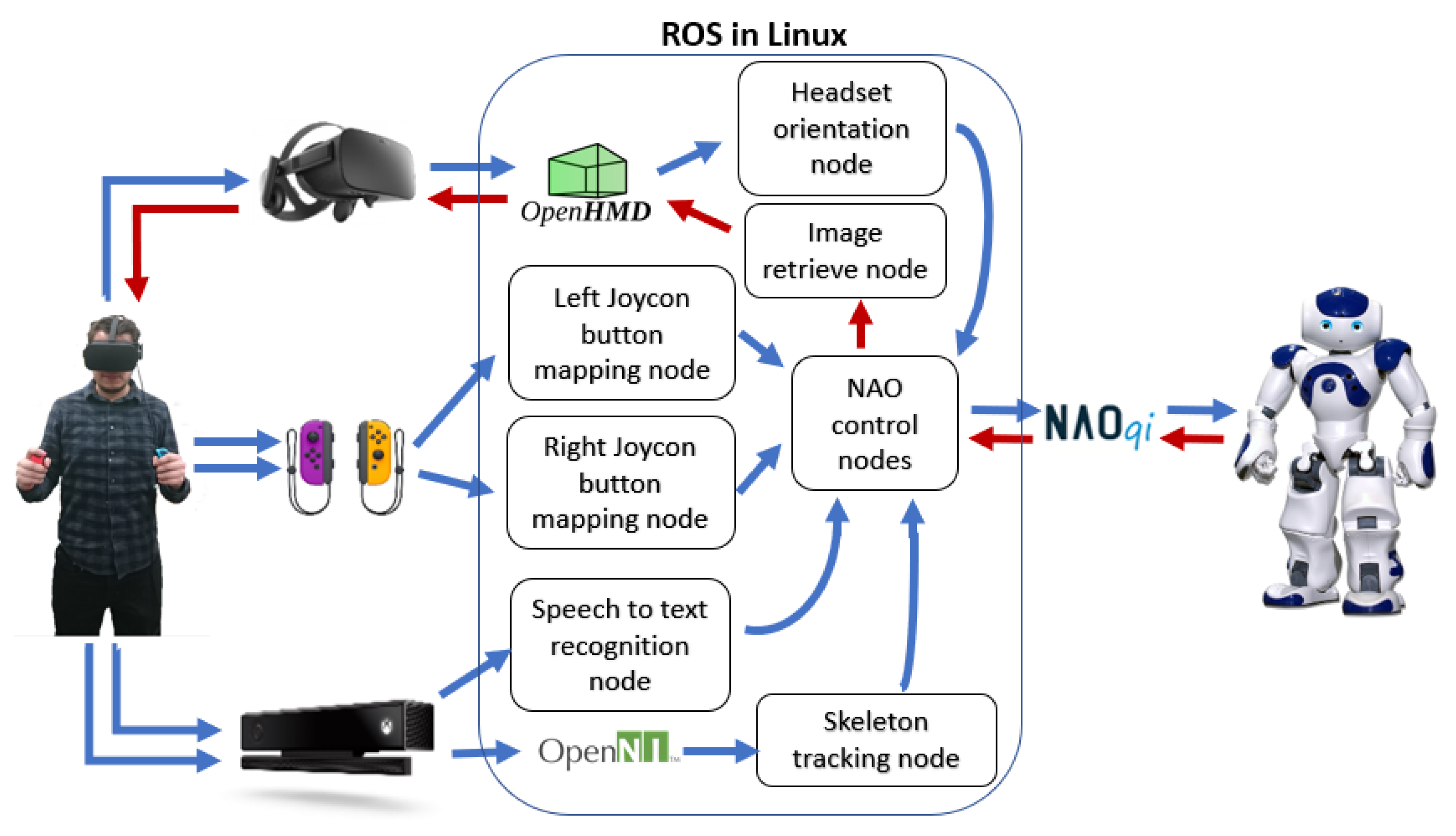
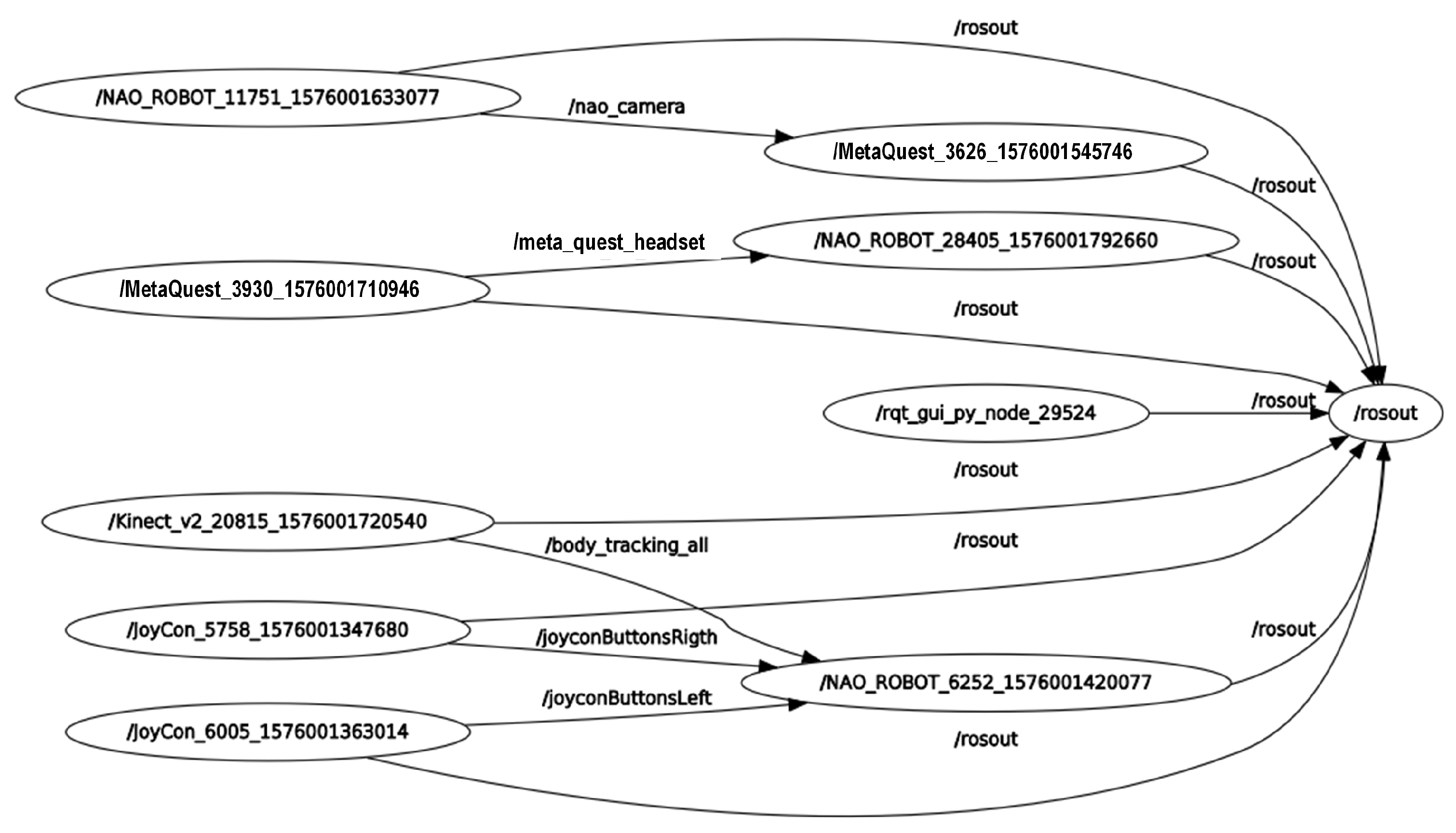
4.3. Node Architecture

A publisher/subscriber communication is used so that a parallel programming architecture can handle the sensing devices and the NAO robot, managing several nodes to control them. This kind of programming improves the data transmission and allows independence in non-sequential procedures that govern the robot’s movements or functionality. Furthermore, message formats with predefined types of variables are used for universal purposes within the project. So, sent data can be read and used regardless of the programming language in which a node was developed. An ROS rqt_graph, including the nodes and topics, is shown in Figure 11.

4.4. Motion Capture

As mentioned before, the libraries OpenNI2 and NiTE2 provide the position and orientation data of 15 joints in the human body. For the mapping of the operator’s arms, the shoulder, elbow, and hand positions for each arm were used. However, to make this mapping, it is necessary to clarify the correspondence of each joint of the arms of NAO to a corporal movement: the joint disposition of the right arm joint is shown in Figure 12. As for the shoulder, there are two degrees of freedom, the “ShoulderPitch” and “ShoulderRoll” joints. The first is equivalent to the movement of abduction and adduction of the shoulder, while the second corresponds to the shoulder flexion and extension movement. In the case of the elbow, there are also two degrees of freedom, “ElbowRoll” and “ElbowYaw”. The first is equivalent to flexion and extension of the elbow, whereas the second is equivalent to internal and external shoulder rotation. Finally, in the case of the wrist, there is the “WristYaw” joint, which is equivalent to the movement of pronation and supination of the elbow.
With these concepts clear, an analytical approach to the reverse kinematics of each robot arm can be made, as explained in the work of Kofinas, Orfanoudakis, and Lagoudakis [38]. The representation of each of the arm manipulators of the robot can be represented as the plot of five joints according to the Modified Denavit–Hartenberg Parameter shown in Table 1 and Figure 13.
The upper limb configuration of humanoid robots, such as the NAO robot, is inspired by the human upper limb. The NAO robot has a redundant kinematics configuration that permits it to perform multiple motions as humans. However, there are infinite solutions to its inverse kinematics issue because of its redundancy structure. Usually, a human uses an optimal joint configuration of the arm when performing motion in space. The elbow position is determined via the first three (shoulder) joints, while its angle (elbow angle) is defined from the wrist position. The rotation configuration of the wrist is determined by the last three joints of the wrist portion. Based on the above analysis of the human upper limb motion, the inverse kinematic solution of NAO’s upper limb is inspired. The elbow angle θ 4 (see Figure 14a) is defined geometrically from the known final destination, the end-effector of the NAO’s upper limb as:
θ 4 = π ± a c o s d w 2 + d e 2 w s 2 2 d e d w
The distance (R) and angle ( α ) situated between d e and the virtual axis that links the end-effector position and the shoulder position permit us to determine the elbow position. From this position, it is easy to determine θ 1 , θ 2 , θ 3 analytically. From the known rotation of the end-effector and angles ( θ 1 , θ 2 , θ 3 , and θ 4 ), the joint θ 5 can be defined easily by the comparison, as given in Section 4.4.3.
When positioning the NAO in special poses, the elbow can be considered to be unrestricted in its rotation about an axis determined by swivel angle ( ϕ ) to the shoulder. The axes of the circle point at the shoulder joint and the wrist joint, meaning that they are perpendicular to the direction of motion. Swivel angle ( ϕ ) is the virtual angle between an elbow’s rotation relative to a virtual axis attached to the shoulder and wrist joints. As the swivel angle changes, the elbow outlines the arc of a circle on a plane whose normal is parallel to the shoulder-to-wrist axis, as shown in Figure 14b. In general, a simple motion does not impose any restrictions on the wrist position, allowing the wrist to be fixed at the desired swivel angle. However, this fixation has no effect on the redundancy of the NAO’s arm. To illustrate the circle from a mathematical perspective, the normal vector of the plane can be defined as follows:
n ^ = w s w s
Then, u ^ is set to be a projection of an axis z ^ selected arbitrarily on the circle:
z ^ = [ 0 0 1 ] T
u ^ = z ^ z ^ n ^ n ^ z ^ z ^ n ^ n ^
and υ ^ is the last component of the orthonormal base:
υ ^ = n ^ × u ^
R and c are the radius and center of the circle, respectively. The radius R is obtained with simple trigonometric relationships. By defining the distance d or center of circle c as (see Figure 14b):
d = C o s α d e n ^
with:
C o s α = d w 2 d e 2 w s 2 2 d e w s
and:
R = S i n α d e
Finally, the elbow position can be characterized as a function of the swivel angle ( ϕ ) about axis u ^ :
e ( ϕ ) = d + R C o s ( ϕ ) u ^ + S i n ( ϕ ) υ ^ + s
where s is the vector shoulder coordinate determined as s s h o u l d e r = 0 0 d s T ; (see Equation (10)). The shoulder is translated by a distance d s on the z-axis as regard to the origin (frame 0 in Figure 12).
P s h o u l d e r = 1 0 T 0 0 0 1 T = 0 0 d s 1 T
where 1 0 T is the first homogeneous transformation matrix obtained by using Table 1. The elbow position is obtained only via the three joints of the shoulder portion. θ 1 , θ 2 and θ 3 :
P e l b o w = 1 0 T 2 1 T 3 2 T 0 0 0 1 T = e x e y e z 1 T
so,
P e l b o w = e x e y e z = d e C 1 S 2 d e S 1 S 2 d s + d e C 2
Here, C i denotes C o s ( θ i ) , and S i denotes S i n ( θ i ) . The wrist joint position depends on θ 1 , θ 2 , θ 3 , and θ 4 . The last joint θ 5 is used to define the wrist orientation.
P e l b o w = 1 0 T 2 1 T 3 2 T 4 3 T 5 4 T 0 0 0 1 T = w x w y w z 1 T = d e C 1 S 2 d w S 4 S 1 S 3 C 1 C 2 C 3 C 1 C 4 S 2 d w S 4 C 1 S 3 + C 2 C 3 S 1 + C 4 S 1 S 2 + d e S 1 S 2 d s + d w C 2 C 4 C 3 S 2 S 4 + d e C 2

4.4.1. Solving θ 1 and θ 2

Obtained from Equation (12), the elbow position is known. So:
e y e x = d e S 1 S 2 d e C 1 S 2 θ 1 = a t a n 2 ( e y , e x )
θ 2 has two solutions, i.e., an analytic solution and a geometric solution, from Equation (12):
C o s ( θ 2 ) = e z d s d e
Yields:
S i n ( θ 2 ) = e x d e C 1 i f C 1 0 S i n ( θ 2 ) = e y d e S 1 O t h e r w i s e
So,
θ 2 = a t a n 2 S i n ( θ 2 ) , e z d s d e
Since joint 2 exists at the shoulder in Figure 15, the coordinate of the origin (joint 1 in Figure 14) is [ 0 0 0 ] , the elbow position is determined by Equation (12), and the distance between the shoulder and elbow d e is constant. The joint θ 2 can be obtained by using the law of cosines:
θ 2 * = π ± a c o s e O 2 d e 2 d s 2 2 d e d s
where θ 2 * is the geometric solution.

4.4.2. Solving θ 3

Joint 3 ( θ 3 ) has two solutions as well, analytic and geometric. To determine θ 3 analytically, we multiply both sides of Equation (13) by 1 0 T 2 1 T 1 :
1 0 T 2 1 T 1 1 0 T 2 1 T 3 2 T 4 3 T 5 4 T 0 0 0 1 T = 1 0 T 2 1 T 1 w x w y w z 1 T
Yields:
d w S 4 C 3 d w C 4 d e d w S 4 S 3 1 = d s S 2 w z S 2 + w x C 1 C 2 + w y C 2 S 1 w x C 1 S 2 w y S 1 S 2 + d s C 2 w z C 2 w y C 1 w x S 1 1 θ 3 = a t a n 2 w y C 1 w x S 1 , d s S 2 w z S 2 + w x C 1 C 2 + w y C 2 S 1
Using the law of cosines (see Figure 16, the geometric solution can obtained as:
θ 3 * = π ± a c o s w w * 2 2 d w 2 2 d w 2
where θ 3 * is the geometric solution.
Two solutions (analytic and geometric) have been obtained for each joint (joints 2 and 3). These solutions are valid for NAO’s upper limb movements.

4.4.3. Solving θ 5

The orientation of the end-effector is given by:
R e n d e f f e c t o r = R 1 R 2 R 3 R 4 R 5 = r 11 r 12 r 13 r 21 r 22 r 23 r 31 r 32 r 33
Consider that R w = R 5 . Substituting it in Equation (22):
R w = R 4 T R 3 T R 2 T R 1 T R e n d e f f e c t o r
where the R e n d e f f e c t o r matrix defines the desired end-effector orientation with respect to the origin. In this condition, Euler angles are used and by comparison, wrist angles can be found as:
t a n ( θ 5 ) = r 33 r 13 θ 5 = a t a n 2 r 31 , r 11
However, based on the work of Md Assad-Uz-Zaman [5], a geometric approach is made to simplify calculations and avoid points of the singularity of the manipulator when converting the three Cartesian positions of the arm (shoulder, elbow, and hand) into the orientation of the angles of the four joints of the arm (two from the shoulder and two from the elbow). First, to make the kinematic analysis of each arm, it is necessary to change the reference frame from the Kinect to the shoulder, which will have the same orientation, transforming the joint position as the subtraction of the Cartesian coordinates between the shoulder and the joint. So, the shoulder coordinates are (0,0,0), and the elbow and hand coordinates will be noted as ( x e , y e , z e ) and ( x h , y h , z h ), respectively. The distance between the shoulder and the elbow is noted as d u p p e r _ a r m , the distance between the elbow and the hand as d f o r e a r m , and the distance between the shoulder and the hand as d a r m . With this, a vector OA is considered as the projection of the vector d u p p e r _ a r m (from the origin to the elbow position) on the z-axis, being the coordinates of A at (0, 0,− z e l b o w ). Now, the angle between d u p p e r _ a r m vectors OA is the angle θ 1 . Further, consider a vector OB as the projection of the vector d u p p e r _ a r m on the x-axis, locating point B at ( x e l b o w ,0,0) position. Therefore, the angle between OB and d u p p e r _ a r m is the angle θ 2 . Angle calculations are shown in Figure 17.
Then,
c o s θ 1 = z e x e 2 + y e 2 + z e 2
Furthermore,
θ 1 = a r c c o s ( c o s θ 1 )
In a similar way,
c o s θ 2 = x e x e 2 + y e 2 + z e 2
Therefore, “Equation (25)” is used to obtain θ 2 . Where, if y e < 0 , θ 2 = θ 2 . For angle θ 3 , consider a plane OABC that passes through y 0 axis and upper arm vector. Then, the angle between this plan and forearm is θ 3 .
s i n θ 3 = z e ( x h x e ) x e ( z h z e ) x e 2 + y e 2 + z e 2 ( x h x e ) 2 + ( y h y e ) 2 + ( z h z e ) 2
Additionally,
c o s θ 3 = ± 1 ( s i n θ 3 ) 2
Therefore,
θ 3 = a r c t a n ( ± s i n θ 3 c o s θ 3 )
Finally, the joint angle θ 4 is determined geometrically using the cosine rule.
( d a r m ) 2 = ( d u p p e r _ a r m ) 2 + ( d f o r e a r m ) 2 2 d u p p e r _ a r m d f o r e a r m c o s θ 4
Then,
θ 4 = a r c c o s ( ( d u p p e r _ a r m ) 2 + ( d f o r e a r m ) 2 ( d a r m ) 2 2 d u p p e r _ a r m d f o r e a r m )
To match the joint angles of the human body with the NAO robot joint orientation, it is necessary to introduce some small changes in the calculation. The modified angles are listed in Table 2.
Another motion tracking that should be taken into account is the NAO’s head, controlled by the headset. It has two joints, the “HeadPitch”, which is equivalent to flexion and extension of the neck, and the “HeadYaw”, which is the lateral rotation to the left and right (Figure 18). The quaternions retrieve from the gyroscope of the headset are transformed into Euler’s angles (XYZ), which have to be the equivalent of the robot joints, as shown in Table 3.

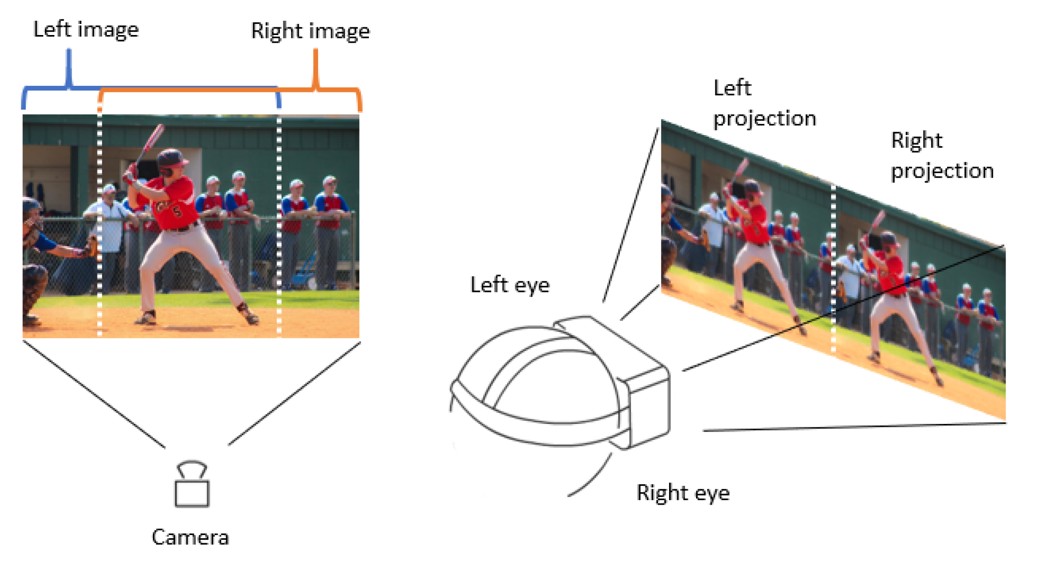
4.5. Image Retrieving

To transmit images directly into the Meta Quest, several conditions need to be considered. Normally, the separation of the human eyes is on average 6 cm [40], which makes each of the eyes see the world from a scarcely different perspective. The brain joins these two views to create a sense of depth. However, if the camera image is sent directly to the headset, having a display that is not divided by eye, and due to the screen’s proximity in sight, the operator cannot comfortably see what the camera is receiving. That is why a quick approach to an immersive virtual reality experience can be made through an image treatment, where the Meta screen should be split into two, having an independent image for each eye. This is done to show 80 percent of the image from the left side and 80 percent from the right side to create the illusion of a stereoscopic image. The process is shown in Figure 19. In this way, a first-person perspective of the robot is easily created. The control of the joints of the robot’s head by the headset orientation builds an immersive experience of the teleoperation.

5. Results and Discussion

5.1. Head Motion Mimic

In this part, we experiment to test the stability of the head following system, in which a person puts the Meta Quest headset on and moves their head to move the NAO’s head. First, the operator will rotate their head 80° to the left direction; then they will rotate 80° to the right direction, pitching up with 40° and pitching down with 70°, respectively. Figure 20 shows the process of the experiment. Figure 21a,b graphs were created, wherein data has been retrieved from head movement angles from the operator and the robot. From the result of the head following experiment, the movement of the user’s head can be followed accurately, allowing the operator to have a first-person view from the camera of the robot. However, it can be seen, especially in Figure 21a that the joints of the robot do not reach angles that the operator does due to design restrictions. However, it can be observed that the joints of the robot in both the yaw and pitch movements do not reach angles that the operator achieves, as per design restrictions [41,42]. Nevertheless, if the operator’s head movement exceeds the limits of movement of the robot’s joints, it will move to the closest angle it can.

5.2. Arm Motion Mimic

In the second experiment, the operator moves his upper limbs to the Kinect camera to retrieve his movements. Again, the operator carried out different positions shown in Figure 22 to evaluate how precise and accurate the robot’s movements are. The operator is asked to make arm movements that only move one of the joints that define the degrees of freedom of the robot arms to collect the information read by the Kinect in comparison to that read by the sensors of the robot. These joints are ShoulderRoll, ShoulderPitch, ELbowYaw, and ELbowRoll. As a result, a series of graphs can be seen in Figure 23, such as the mapping of the human body, when the arms are facing the chest, which causes the sensor to make mistakes when interpreting the movement joints of the operator, making the robot’s movement not precise. In addition, the fact that for effective body tracking, the operator must be as the front of the sensor as possible, because if he rotates, the interpretation of the movement of the arms becomes inaccurate, by mapping the operator’s torso incorrectly and at the same time the position of the furthest arm from the camera. However, when the operator stays in front of the sensor, the robot follows the operator’s movement in the four joints that are mapped with this sensor continuously.

5.3. Body Motion Mimic

In the following experiment, the entire Kinect, Meta Quest, and Joycons are used. We want to evaluate the use of the three devices simultaneously to control the robot’s movement to see if there is any communication problem when the three devices are in action. In addition, the change in teleoperation modality is also evaluated through the controls to see the independence of the operator in the process, as can be seen in Figure 24.
It was observed that the use of ROS allows the control of different sections of the robot without any problem in the loss of information because of default TCPROS transport layer of messages and services. In multi-modal teleportation where UDP transport protocol is used, a loss of information is observed [43]. In addition, it was observed that the change between teleoperation modalities is done quickly by utilizing the buttons of the Joycons, which allows this developed process to have the facility of only needing the operator to control the entire process. One aspect to be highlighted is that the first perspective vision with the NAO camera is not as immersive as expected, making the movements of the arms from the head’s perspective feel not as natural as the movements of the operators’ arms seen from his perspective. Nonetheless, another experiment in which the NAO held a market in its hand will be teleoperated to draw lines on a paper. As shown in Figure 25, the operator can control the robot’s hand and see what the robot is doing with the headset. Nevertheless, the teleoperation experience can be improved by controlling the torso orientation to limb the robot and had more workspace than just the reach area of both hands when the robot is standing on its foot.

5.4. Safety Routines

There have been plenty of safety routines when the teleoperation protocol is operative. When using the Kinect, the user must be in full view of the sensor. The entire body is adequately swallowed, and the movement is not misinterpreted by being hidden or obscured by some other object. Therefore, two requirements must be ensured before beginning teleoperation. The first one is that the sensor does not find more than one person in the visibility zone of the Kinect since having two or more people could result in the interpretation of a human skeleton with the mobile joints of all people within the visibility area. The second one is that when obtaining the information of the 19 traceable joints of the human body by the sensor, they have to have a confidence level equal to one to guarantee the least amount of noise between the recovered data. The teleoperation will stop if one of these requirements is not fulfilled. It is also worth highlighting the use of Nintendo Switch controls. Because of their ergonomics, they can allow the separation of both arms, compared to any other video game control. Still, these enable the operator to interact with the teleoperation software without needing a second person to configure and implement the protocol. Furthermore, during the experimental phase, it was found that validating the teleoperation and safety routines in a safe environment is always important. For this purpose, the Choreographer simulated the version on the NAO connected via Naoqi to create the first tests. Nonetheless, it is essential to acknowledge that the NAO robot acts more stable in the simulated world than in the real world.

5.5. Discussion

The proposed approach was validated using the Kinect V2 sensor, Meta Quest headset, Nintendo Switch Joycons, and the NAO robot. There is ease between changing the operating modes of the robot, using only the controls, which allows the robot to move in different points easily. More importantly, it allows the follow-up of the arm movements as the operator’s head easily, allowing him to have an immersive experience when controlling the robot, seeing it from the robot’s point of view and speaking through it. Sources of latency were considered originating from the hardware and physical limitations of communication. While transferring videos and motion data we experienced negligible latency (<100 ms). It is clear to think that there are different applications for this telepresence, such as long-distance teaching with active users’ active participation. Moreover, taking into account the work of it, it is possible to say that there is potential to carry out interaction therapies with autistic children [44,45,46,47,48], improving the communication skills of the patients. Therefore, based on the work of Malik, Yussof, and Hanapiah in [49] and Shamsuddin et al. in [50], a therapy work could be proposed with the following experimental layout to analyze the advantages of the teleoperation system to be used for therapeutic purposes, as shown in Figure 26.
However, regarding future work, there are many possibilities to improve the teleoperation system. For example, the controls of Nintendo Switch are optimal for the proposed teleoperation, being ergonomic, and allowing the separation of the operator’s arms when the manipulation of the robot is in progress. Unfortunately, a driver is not found at the moment that allows the IMU of the Joycons to be collected in Linux. Therefore, one of the first tasks to improve this system is to access their information to control the movement of the robot’s wrist and control their HD rumble with haptic teleoperation purposes by receiving feedback from the environment in which the robot’s hands are interacting. At the same time, using a real-sense camera instead of one that the robot has in its forehead will allow a more immersive experience having more resolution and panoramic vision than the one currently used. This would allow the mapping of the place in real-time by the depth camera functionality, potentially using the robot’s trajectories. However, to use this type of camera, it is required that the robot carries a raspberry pi with it so that the video transmission of the camera does not depend on cables, restricting the movements of the NAO. Finally, creating an application in a virtual reality environment that allows more control of the teleoperation from the VR glasses and not from the computer screen display is advised.

6. Conclusions

From the experimental results, it can be concluded that the teleoperation framework developed in this study can be used for therapeutic purposes. Our designed control architecture and its integration with other components in ROS platform make this teleoperation possible. The proposed approach is validated through the robot’s movement to perform different assignments. The gesture teleoperation system, together with the user interface, allows the robot to imitate arm movements and act according to the operator’s predefined body movements simultaneously. The proposed approach offers an architecture that can have many applications beyond pure teleoperation within the area of socially assistive robotics, where robots assist through social interaction. Many authors agree that humanoid robots can help assist patients with disabilities or pediatric therapy such as physiotherapy because children tend to accept robots more naturally than adults, and they are motivated to replicate robot’s movement as a therapy. The developed software could help the therapists without programming skills record the exercises on the robot and provide a tool for recording or learning sequences of poses from the mimicked movements.

Author Contributions

J.C.C.: conceptualization, methodology, software, formal analysis, investigation, data curation, original draft preparation. M.S.H.S.: methodology, original draft preparation, visualization. B.B.: control method development, writing—review and editing. L.M.M.: control method analysis, writing—review and editing. R.F.: data analysis, writing—review and editing. H.U.A.: writing—review and editing. M.H.R.: investigation, supervision, project administration, writing—review and editing. All authors have read and agreed to the published version of the manuscript.

Funding

This research is partially funded by the BioRobotics Lab, University of Wisconsin- Milwaukee, USA.

Institutional Review Board Statement

The study was conducted in accordance with the Declaration of Helsinki and approved by the Institutional Review Board of the University of Wisconsin-Milwaukee. Informed consent was obtained from all subjects for both study participation and publication of identifying information/images. The study protocol (UWM IRB# 17.352) has been reviewed by the University of Wisconsin Milwaukee and approved as minimal risk Expedited under Category 1b as governed by 45 CFR 46.110.

Informed Consent Statement

Informed consent was obtained from all subjects involved in the study.

Data Availability Statement

The data collected and analyzed during this study are available from the corresponding author upon reasonable request.

Conflicts of Interest

The authors declare no conflict of interest.

References

  1. Khandelwal, P.; Zhang, S.; Sinapov, J.; Leonetti, M.; Thomason, J.; Yang, F.; Gori, I.; Svetlik, M.; Khante, P.; Lifschitz, V.; et al. BWIBots: A platform for bridging the gap between AI and human–robot interaction research. Int. J. Robot. Res. 2017, 36, 635–659. [Google Scholar] [CrossRef] [Green Version]
  2. Setapen, A.; Quinlan, M.; Stone, P. Beyond teleoperation: Exploiting human motor skills with marionet. In Proceedings of the AAMAS 2010 Workshop on Agents Learning Interactively from Human Teachers (ALIHT), Toronto, ON, Canada, 10–14 May 2010. [Google Scholar]
  3. Halder, S.; Afsari, K.; Chiou, E.; Patrick, R.; Hamed, K.A. Construction inspection & monitoring with quadruped robots in future human-robot teaming: A preliminary study. J. Build. Eng. 2023, 65, 105814. [Google Scholar]
  4. Parasuraman, S.; Hock, P.S.; Khan, M.A.; Singh, D.K.J.; Han, C.Y. Behaviour coordinations and motion synchronizations for humanoid robot. Int. J. Adv. Robot. Syst. 2017, 14, 1–15. [Google Scholar] [CrossRef]
  5. Assad-Uz-Zaman, M. Design and Development of a Robot Guided Rehabilitation Scheme for Upper Extremity Rehabilitation. Ph.D. Thesis, The University of Wisconsin-Milwaukee, Milwaukee, WI, USA, 2017. [Google Scholar]
  6. Burns, R.B.; Seifi, H.; Lee, H.; Kuchenbecker, K.J. Getting in touch with children with autism: Specialist guidelines for a touch-perceiving robot. Paladyn J. Behav. Robot. 2021, 12, 115–135. [Google Scholar] [CrossRef]
  7. Lakatos, G.; Wood, L.J.; Syrdal, D.S.; Robins, B.; Zaraki, A.; Dautenhahn, K. Robot-mediated intervention can assist children with autism to develop visual perspective taking skills. Paladyn J. Behav. Robot. 2021, 12, 87–101. [Google Scholar] [CrossRef]
  8. Louie, W.Y.G.; Korneder, J.; Abbas, I.; Pawluk, C. A study on an applied behavior analysis-based robot-mediated listening comprehension intervention for ASD. Paladyn J. Behav. Robot. 2021, 12, 31–46. [Google Scholar] [CrossRef]
  9. Cooper, S.; Ros, R. Towards the Deployment of a Social Robot at an Elderly Day Care Facility. In Social Robotics: Proceedings of the 14th International Conference, ICSR 2022, Florence, Italy, 13–16 December 2022; Proceedings, Part II; Springer: Berlin/Heidelberg, Germany, 2023; pp. 277–287. [Google Scholar]
  10. Assad-Uz-Zaman, M.; Islam, M.R.; Rahman, M.H.; Wang, Y.C.; McGonigle, E. Kinect controlled NAO robot for telerehabilitation. J. Intell. Syst. 2021, 30, 224–239. [Google Scholar] [CrossRef]
  11. Stanton, C.; Bogdanovych, A.; Ratanasena, E. Teleoperation of a humanoid robot using full-body motion capture, example movements, and machine learning. In Proceedings of the Australasian Conference on Robotics and Automation, Wellington, New Zealand, 3–5 December 2012. [Google Scholar]
  12. Dajles, D.; Siles, F. Teleoperation of a Humanoid Robot Using an Optical Motion Capture System. In Proceedings of the 2018 IEEE International Work Conference on Bioinspired Intelligence (IWOBI), San Carlos, Costa Rica, 18–20 July 2018; pp. 1–8. [Google Scholar]
  13. Avalos, J.; Cortez, S.; Vasquez, K.; Murray, V.; Ramos, O.E. Telepresence using the kinect sensor and the NAO robot. In Proceedings of the 2016 IEEE 7th Latin American Symposium on Circuits Systems (LASCAS), Florianopolis, Brazil, 28 February–2 March 2016; pp. 303–306. [Google Scholar] [CrossRef]
  14. Almetwally, I.; Mallem, M. Real-time tele-operation and tele-walking of humanoid Robot Nao using Kinect Depth Camera. In Proceedings of the 2013 10th IEEE International Conference on Networking, Sensing and Control (ICNSC), Evry, France, 10–12 April 2013; pp. 463–466. [Google Scholar] [CrossRef]
  15. Rodriguez, I.; Astigarraga, A.; Jauregi, E.; Ruiz, T.; Lazkano, E. Humanizing NAO robot teleoperation using ROS. In Proceedings of the 2014 IEEE-RAS International Conference on Humanoid Robots, Madrid, Spain, 18–20 November 2014; pp. 179–186. [Google Scholar] [CrossRef]
  16. Gong, L.; Chen, B.; Xu, W.; Liu, C.; Li, X.; Zhao, Z.; Zhao, L. Motion similarity evaluation between human and a tri-co robot during real-time imitation with a trajectory dynamic time warping model. Sensors 2022, 22, 1968. [Google Scholar] [CrossRef]
  17. Huamanchahua, D.; Ortiz-Zacarias, J.; Rojas-Tapara, Y.; Taza-Aquino, Y.; Quispe-Quispe, J. Human cinematic capture and movement system through kinect: A detailed and innovative review. In Proceedings of the 2022 IEEE International IOT, Electronics and Mechatronics Conference (IEMTRONICS), Toronto, ON, Canada, 1–4 June 2022; pp. 1–7. [Google Scholar]
  18. Cruz-Ramírez, S.R.; García-Martínez, M.; Olais-Govea, J.M. NAO robots as context to teach numerical methods. Int. J. Interact. Des. Manuf. 2022, 16, 1337–1356. [Google Scholar] [CrossRef]
  19. Mukherjee, S.; Paramkusam, D.; Dwivedy, S.K. Inverse kinematics of a NAO humanoid robot using kinect to track and imitate human motion. In Proceedings of the 2015 International Conference on Robotics, Automation, Control and Embedded Systems (RACE), Chennai, India, 18–20 February 2015; pp. 1–7. [Google Scholar] [CrossRef]
  20. Li, C.; Yang, C.; Liang, P.; Cangelosi, A.; Wan, J. Development of Kinect based teleoperation of Nao robot. In Proceedings of the 2016 International Conference on Advanced Robotics and Mechatronics (ICARM), Macau, China, 18–20 August 2016; pp. 133–138. [Google Scholar] [CrossRef] [Green Version]
  21. Mello, R.C.; Scheidegger, W.M.; Scheidegger, W.M.; Múnera, M.C.; Cifuentes, C.A.; Ribeiro, M.R.N. The PoundCloud framework for ROS-based cloud robotics: Case studies on autonomous navigation and human–robot interaction. Robot. Auton. Syst. 2022, 150, 103981. [Google Scholar] [CrossRef]
  22. Casañ, G.A.; Cervera, E.; Moughlbay, A.A.; Alemany, J.; Martinet, P. ROS-based online robot programming for remote education and training. In Proceedings of the 2015 IEEE International Conference on Robotics and Automation (ICRA), Seattle, WA, USA, 26–30 May 2015; pp. 6101–6106. [Google Scholar] [CrossRef] [Green Version]
  23. Ajili, I.; Mallem, M.; Didier, J. Gesture recognition for humanoid robot teleoperation. In Proceedings of the 2017 26th IEEE International Symposium on Robot and Human Interactive Communication (RO-MAN), Lisbon, Portugal, 28 August–1 September 2017; pp. 1115–1120. [Google Scholar] [CrossRef] [Green Version]
  24. Sripada, A.; Asokan, H.; Warrier, A.; Kapoor, A.; Gaur, H.; Patel, R.; Sridhar, R. Teleoperation of a humanoid robot with motion imitation and legged locomotion. In Proceedings of the 2018 3rd International Conference on Advanced Robotics and Mechatronics (ICARM), Singapore, 18–20 July 2018; pp. 375–379. [Google Scholar]
  25. Fritsche, L.; Unverzag, F.; Peters, J.; Calandra, R. First-person tele-operation of a humanoid robot. In Proceedings of the 2015 IEEE-RAS 15th International Conference on Humanoid Robots (Humanoids), Seoul, Korea, 3–5 November 2015; pp. 997–1002. [Google Scholar] [CrossRef] [Green Version]
  26. NAO the Humanoid and Programmable Robot|SoftBank Robotics. 2021. Available online: https://www.softbankrobotics.com/emea/en/nao (accessed on 9 February 2023).
  27. NAO—Technical Overview—Aldebaran 2.1.4.13 Documentation. 2017. Available online: http://doc.aldebaran.com/2-1/family/robots/index_robots.html (accessed on 30 December 2022).
  28. NAO—Actuator & Sensor List—Aldebaran 2.1.4.13 Documentation. 2017. Available online: http://doc.aldebaran.com/2-1/family/nao_dcm/actuator_sensor_names.html#actuator-sensor-list-nao (accessed on 9 February 2023).
  29. NAO—Versions and Body Type—Aldebaran 2.1.4.13 Documentation. 2017. Available online: http://doc.aldebaran.com/2-1/family/body_type.html#nao-version-bodytype (accessed on 9 February 2023).
  30. ROS: Home. 2022. Available online: https://www.ros.org (accessed on 30 December 2022).
  31. Kinect—Windows App Development. 2021. Available online: https://developer.microsoft.com/en-us/windows/kinect (accessed on 9 February 2023).
  32. González, A.; Gonzalez-Galvan, E.J.; Maya, M.; Cardenas, A.; Piovesan, D. Estimation of camera-space manipulation parameters by means of an extended Kalman filter: Applications to parallel robots. Int. J. Adv. Robot. Syst. 2019, 16, 1729881419842987. [Google Scholar] [CrossRef]
  33. Falahati, S. OpenNI Cookbook; Packt Publishing: Birmingham, UK, 2023. [Google Scholar]
  34. Stübl, G.; Heindl, C.; Ebenhofer, G.; Bauer, H.; Pichler, A. Lessons Learned from Human Pose Interaction in an Industrial Spatial Augmented Reality Application. Procedia Comput. Sci. 2023, 217, 912–917. [Google Scholar] [CrossRef]
  35. Meta Quest 2: Immersive All-In-One VR Headset|Meta Store. 2022. Available online: https://www.meta.com/quest/products/quest-2/?utm_source=www.oculus.com&utm_medium=dollyredirect (accessed on 30 December 2022).
  36. OpenHMD–FOSS HMD Drivers for the People. 2022. Available online: http://www.openhmd.net (accessed on 30 December 2022).
  37. Nintendo Switch. 2021. Available online: https://store.nintendo.com/nintendo-switch/joy-con-controllers.html (accessed on 16 June 2021).
  38. Kofinas, N.; Orfanoudakis, E.; Lagoudakis, M.G. Complete analytical inverse kinematics for NAO. In Proceedings of the 2013 13th International Conference on Autonomous Robot Systems, Lisbon, Portugal, 24 April 2013; pp. 1–6. [Google Scholar] [CrossRef]
  39. Brahmi, B.; Saad, M.; Rahman, M.H.; Ochoa-Luna, C. Cartesian trajectory tracking of a 7-DOF exoskeleton robot based on human inverse kinematics. IEEE Trans. Syst. Man Cybern. Syst. 2017, 49, 600–611. [Google Scholar] [CrossRef]
  40. WebVR Concepts—Web APIs|MDN. 2022. Available online: https://developer.mozilla.org/en-US/docs/Web/API/WebVR_API/Concepts (accessed on 30 December 2022).
  41. Mao, X.; Wen, X.; Song, Y.; Li, W.; Chen, G. Eliminating drift of the head gesture reference to enhance Google Glass-based control of an NAO humanoid robot. Int. J. Adv. Robot. Syst. 2017, 14, 1–10. [Google Scholar] [CrossRef] [Green Version]
  42. Melinte, O.; Vladareanu, L.; Munteanu, L.; Yu, H.; Cang, S.; Hou, Z.; Bian, G.; Wang, H. Haptic intelligent interfaces for NAO robot hand control. In Proceedings of the 2015 International Conference on Advanced Mechatronic Systems (ICAMechS), Beijing, China, 22–24 August 2015; pp. 50–55. [Google Scholar] [CrossRef]
  43. Kittel-Ouimet, T. Commande d’un Bras Exosquelette Robotique à Sept Degrés de Liberté. Ph.D. Thesis, École de Technologie Supérieure, Montréal, QC, Canada, 2012. [Google Scholar]
  44. Nadel, J.; Grynszpan, O.; Martin, J.C. Autism and socially interactive agents. In The Handbook on Socially Interactive Agents: 20 Years of Research on Embodied Conversational Agents, Intelligent Virtual Agents, and Social Robotics Volume 2: Interactivity, Platforms, Application; Association for Computing Machinery: New York, NY, USA, 2022; pp. 437–462. [Google Scholar]
  45. Ismail, L.; Shamsuddin, S.; Yusoff, H.; Hanapiah, F.; Zahari, N. Robot-based Intervention Program for Autistic Children with Humanoid Robot NAO: Initial Response in Stereotyped Behavior. Procedia Eng. 2012, 41, 1441–1447. [Google Scholar] [CrossRef] [Green Version]
  46. Taheri, A.R.; Alemi, M.; Meghdari, A.; PourEtemad, H.R.; Basiri, N.M. Social robots as assistants for autism therapy in Iran: Research in progress. In Proceedings of the 2014 Second RSI/ISM International Conference on Robotics and Mechatronics (ICRoM), Tehran, Iran, 15–17 October 2014; pp. 760–766. [Google Scholar] [CrossRef]
  47. Shamsuddin, S.; Yussof, H.; Miskam, M.A.; Hamid, A.C.; Malik, N.A.; Hashim, H. Humanoid robot NAO as HRI mediator to teach emotions using game-centered approach for children with autism. In Proceedings of the HRI 2013 Workshop on Applications for Emotional Robots, Tokyo, Japan, 3–6 March 2013; Volume 33. [Google Scholar]
  48. Pennisi, P.; Tonacci, A.; Tartarisco, G.; Billeci, L.; Ruta, L.; Gangemi, S.; Pioggia, G. Autism and social robotics: A systematic review. Autism Res. 2016, 9, 165–183. [Google Scholar] [CrossRef] [PubMed]
  49. Malik, N.A.; Yussof, H.; Hanapiah, F.A. Development of imitation learning through physical therapy using a humanoid robot. Procedia Comput. Sci. 2014, 42, 191–197. [Google Scholar] [CrossRef] [Green Version]
  50. Shamsuddin, S.; Yussof, H.; Ismail, L.; Hanapiah, F.A.; Mohamed, S.; Piah, H.A.; Zahari, N.I. Initial response of autistic children in human-robot interaction therapy with humanoid robot NAO. In Proceedings of the 2012 IEEE 8th International Colloquium on Signal Processing and Its Applications, Malacca, Malaysia, 23–25 March 2012; pp. 188–193. [Google Scholar] [CrossRef]
Figure 1. All joints in the NAO robot at initial positions [28].
Micromachines 14 00461 g001
Figure 2. All sensors in NAO robot [29].
Micromachines 14 00461 g002
Figure 3. A typical ROS Model: System components.
Micromachines 14 00461 g003
Figure 4. Skeleton tracking with the Kinect sensor and OpenNI2.
Micromachines 14 00461 g004
Figure 5. Modular software architecture of the teleoperation model: consists of different nodes to read out data from Kinect, Meta Quest, and Joycon Controllers and another module to control the robot. The blue lines indicate position data measured or actions on the operator side and resulting into motion or operation of the NAO robot. The red lines indicate visual data collected on the robot and provided as feedback to the operator.
Micromachines 14 00461 g005
Figure 6. Button disposition of the Joycons.
Micromachines 14 00461 g006
Figure 7. Software architecture of the data acquisition with the Kinect sensor.
Micromachines 14 00461 g007
Figure 8. Software architecture of the data acquisition with the Meta Quest.
Micromachines 14 00461 g008
Figure 9. Software architecture of the data acquisition with the Joycon controllers.
Micromachines 14 00461 g009
Figure 10. Button disposition of the Joycons.
Micromachines 14 00461 g010
Figure 11. ROS rqt_graph, including the nodes and topics.
Micromachines 14 00461 g011
Figure 12. Right arm joint of the NAO robot [27].
Micromachines 14 00461 g012
Figure 13. Link frame attachments to the human right limb.
Micromachines 14 00461 g013
Figure 14. (a) Analysis of human upper limb motion. (b) Swivel angle ( ϕ ) configuration [39].
Micromachines 14 00461 g014
Figure 15. Joint θ 2 geometrical solution [39].
Micromachines 14 00461 g015
Figure 16. Geometrical solution of joint θ 3 [39].
Micromachines 14 00461 g016
Figure 17. Arm angles calculation.
Micromachines 14 00461 g017
Figure 18. Head joint of the NAO robot [27].
Micromachines 14 00461 g018
Figure 19. Treatment of the camera image.
Micromachines 14 00461 g019
Figure 20. Process of imitation for NAO robot head following.
Micromachines 14 00461 g020
Figure 21. Result of head following experiment for both human and NAO robot. (a) Head pitch motion (b) Head Yaw motion.
Micromachines 14 00461 g021
Figure 22. Process of imitation for NAO robot upper limb following.
Micromachines 14 00461 g022
Figure 23. Result of upper limb following experiment for both human and NAO robot. (a) Shoulder roll motion (b) Shoulder pitch motion (c) Elbow yaw motion, and (d) Elbow roll motion.
Micromachines 14 00461 g023
Figure 24. Process of imitation for NAO robot joint following.
Micromachines 14 00461 g024
Figure 25. Result of marker manipulation with the NAO robot.
Micromachines 14 00461 g025
Figure 26. Draft of a room setup for the experiment.
Micromachines 14 00461 g026
Table 1. Modified Denavit–Hartenberg parameters.
Joint(i) a i 1 d i α i 1 θ i
1000 θ 1 π /2
2 π /200 θ 2
3 π /2 d u p p e r a r m 0 θ 3
4 π /200 θ 4
5 π /2 d f o r e a r m 0 θ 5
Table 2. NAO joint angles.
AngleNAO JointModified Angle
θ 1 RShoulderRoll θ 1 − 90°
θ 2 RShoulderPitch θ 2
θ 3 RElbowYaw90°− θ 3
θ 4 RElbowRoll180°− θ 4
θ 1 LShoulderRoll90°− θ 1
θ 2 LShoulderPitch θ 2
θ 3 LElbowYaw−90°− θ 3
θ 4 LElbowRoll θ 4 −180°
Table 3. NAO head angles.
AngleOR Angle NameNAO JointModified Angle
θ 1 RollHeadPitch θ 1
θ 2 PitchHeadYaw θ 2
Disclaimer/Publisher’s Note: The statements, opinions and data contained in all publications are solely those of the individual author(s) and contributor(s) and not of MDPI and/or the editor(s). MDPI and/or the editor(s) disclaim responsibility for any injury to people or property resulting from any ideas, methods, instructions or products referred to in the content.

