
An All-Silicon Resonant Pressure Microsensor Based on Eutectic Bonding
 ,
, 
Abstract
:1. Introduction
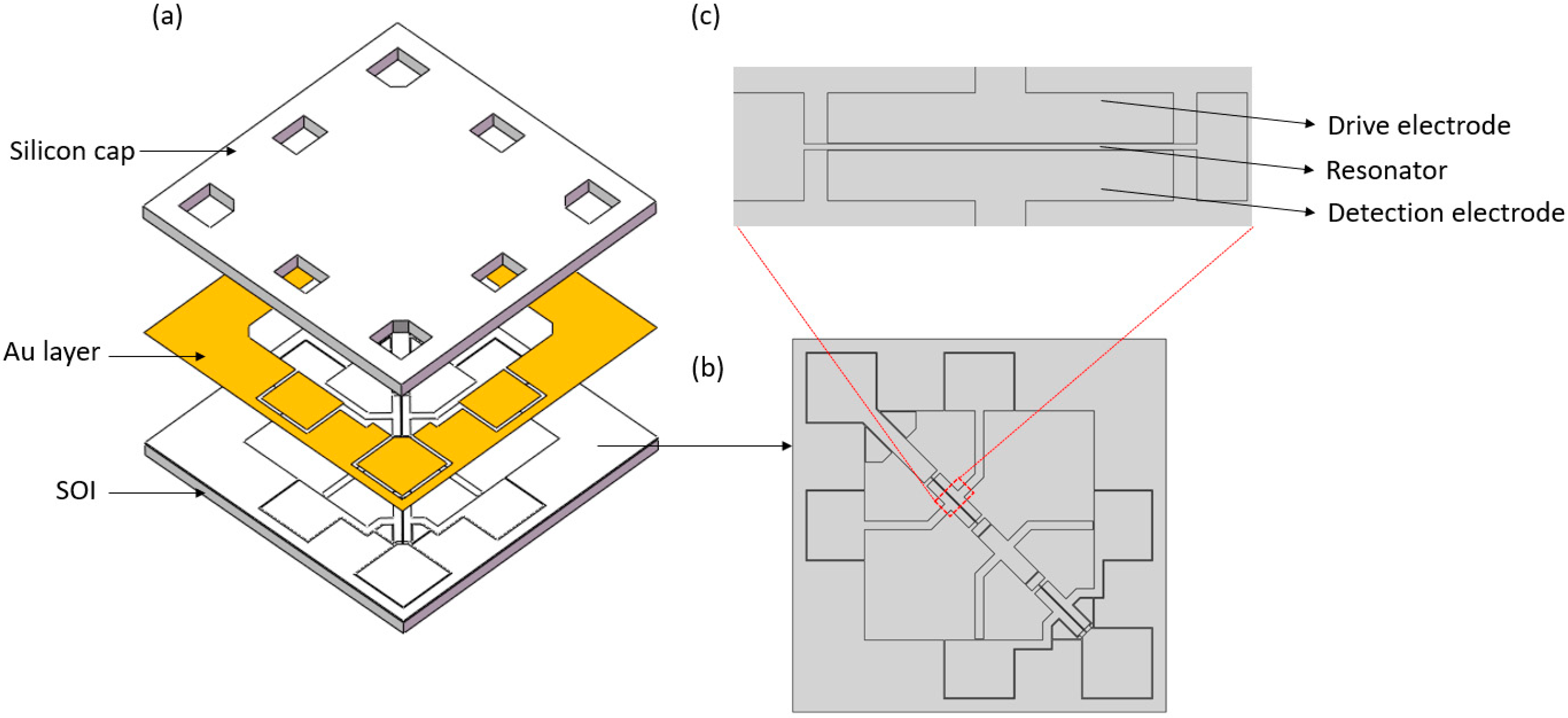
2. Design and Simulation
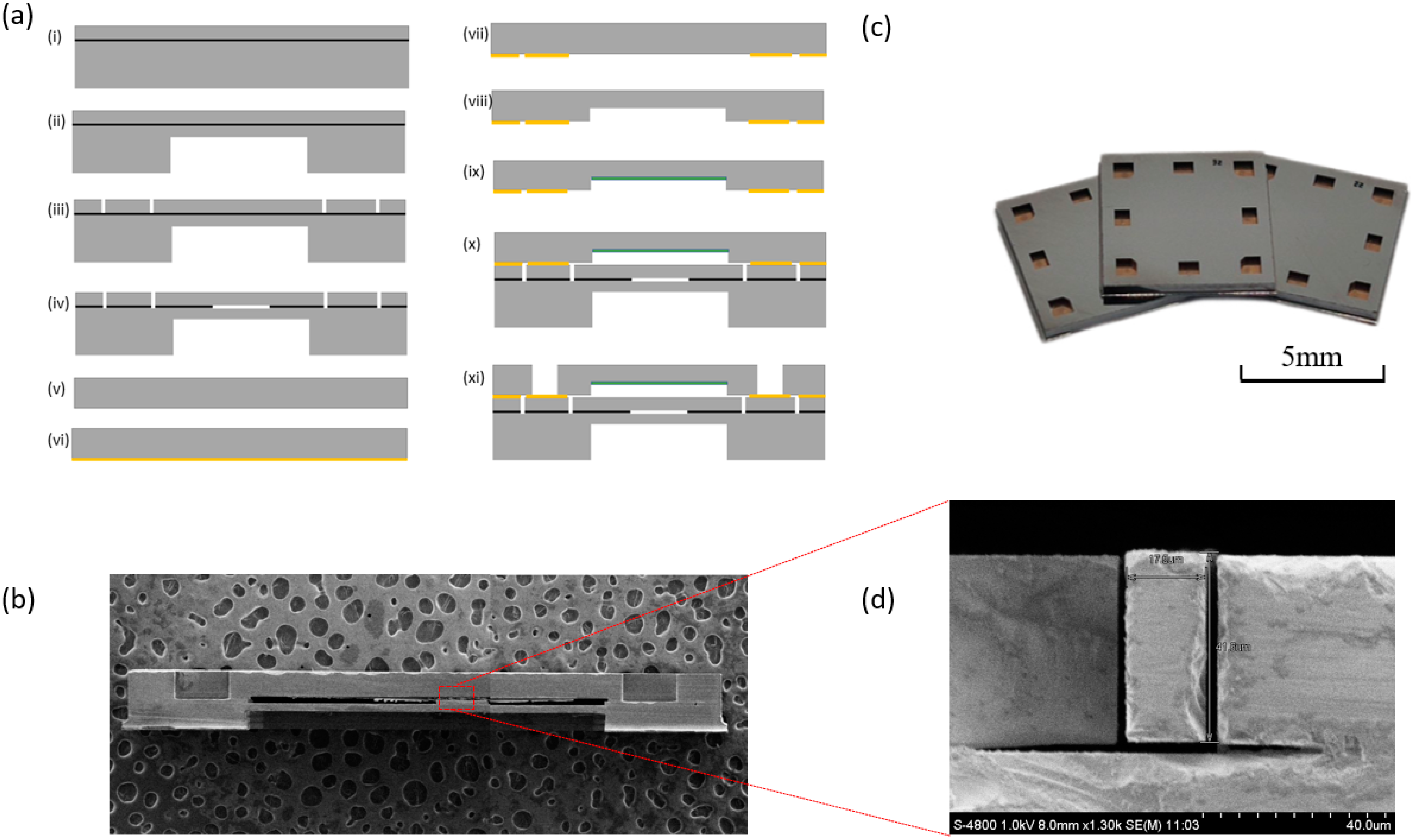
3. Fabrication
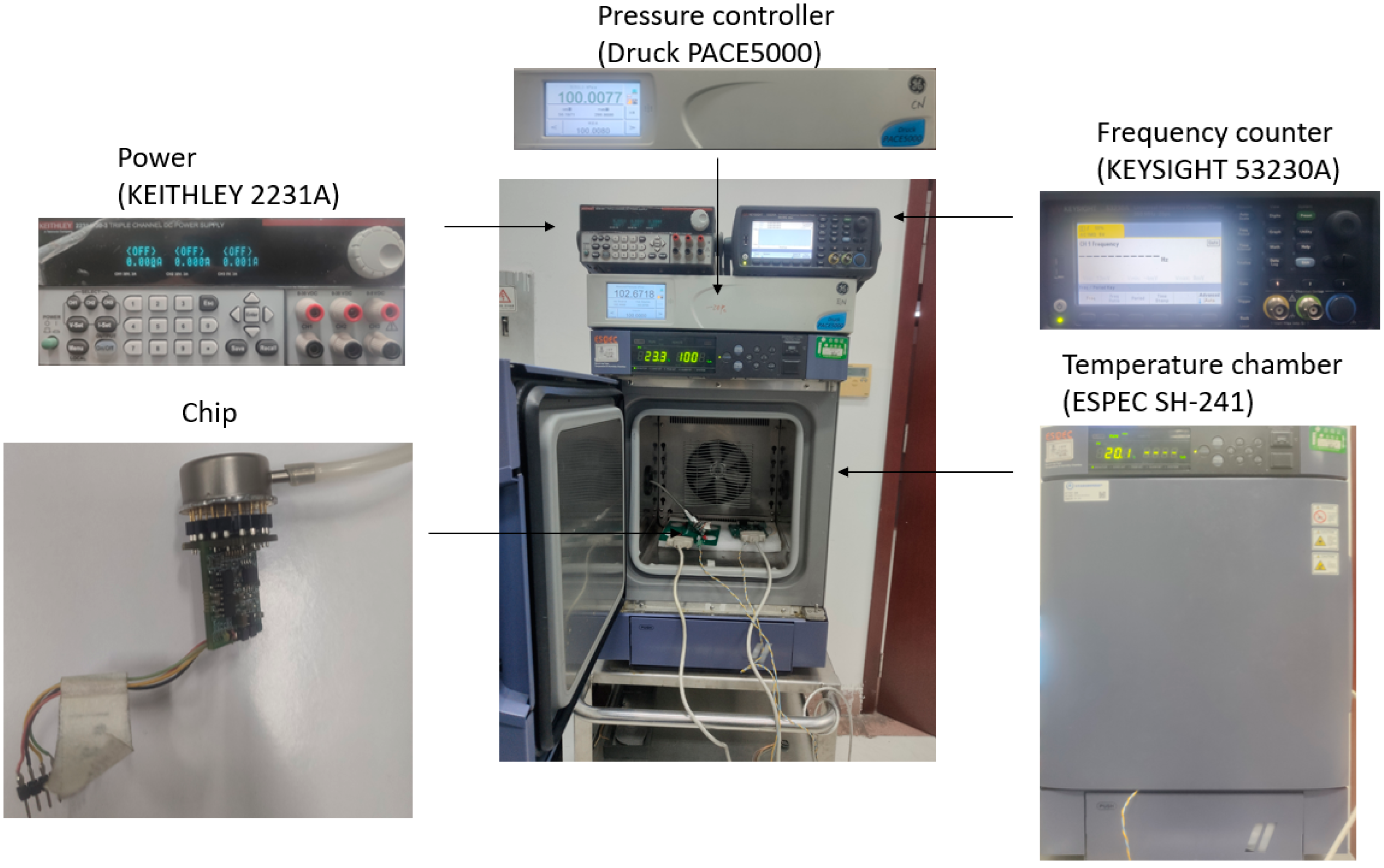
4. Characterization
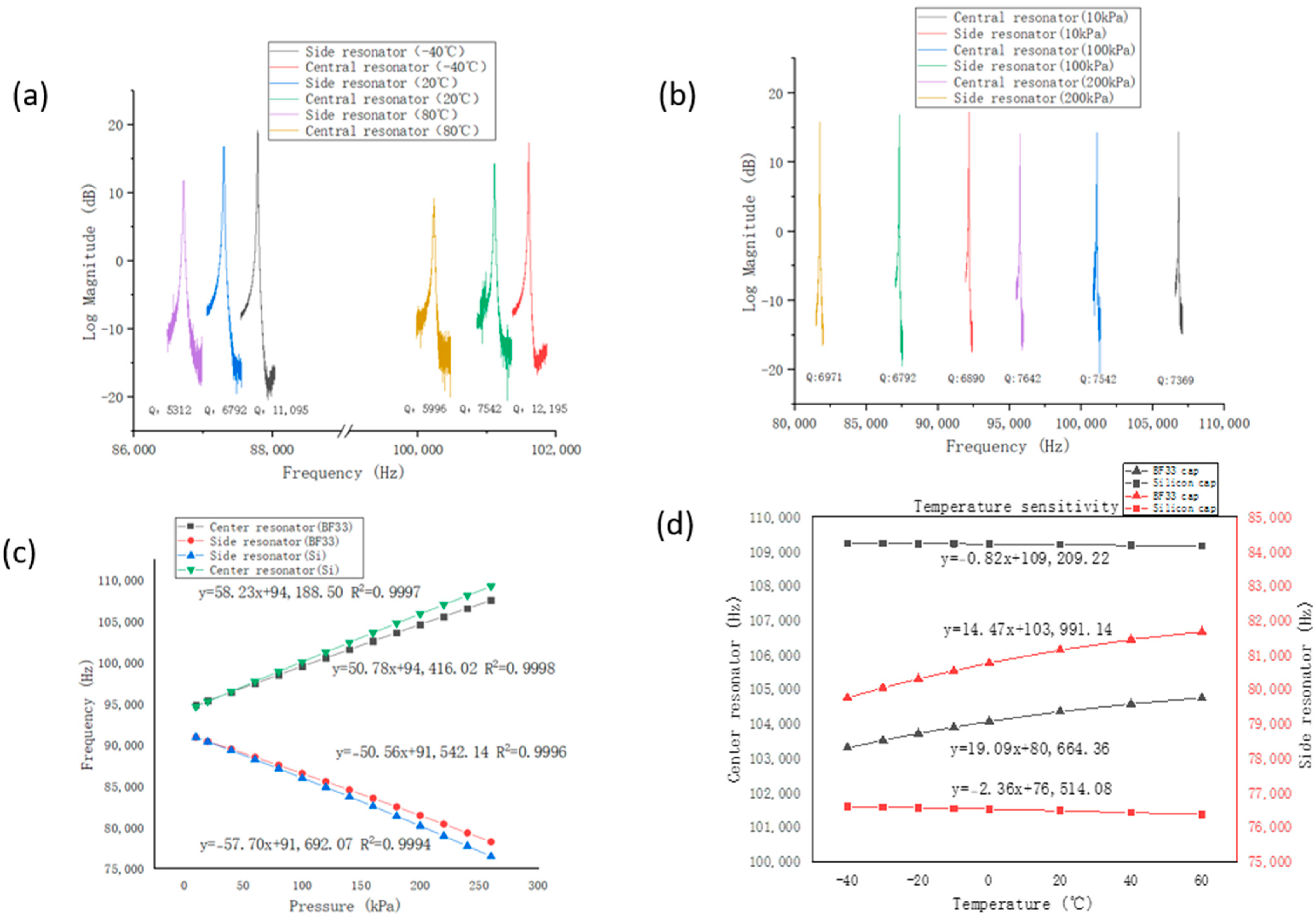
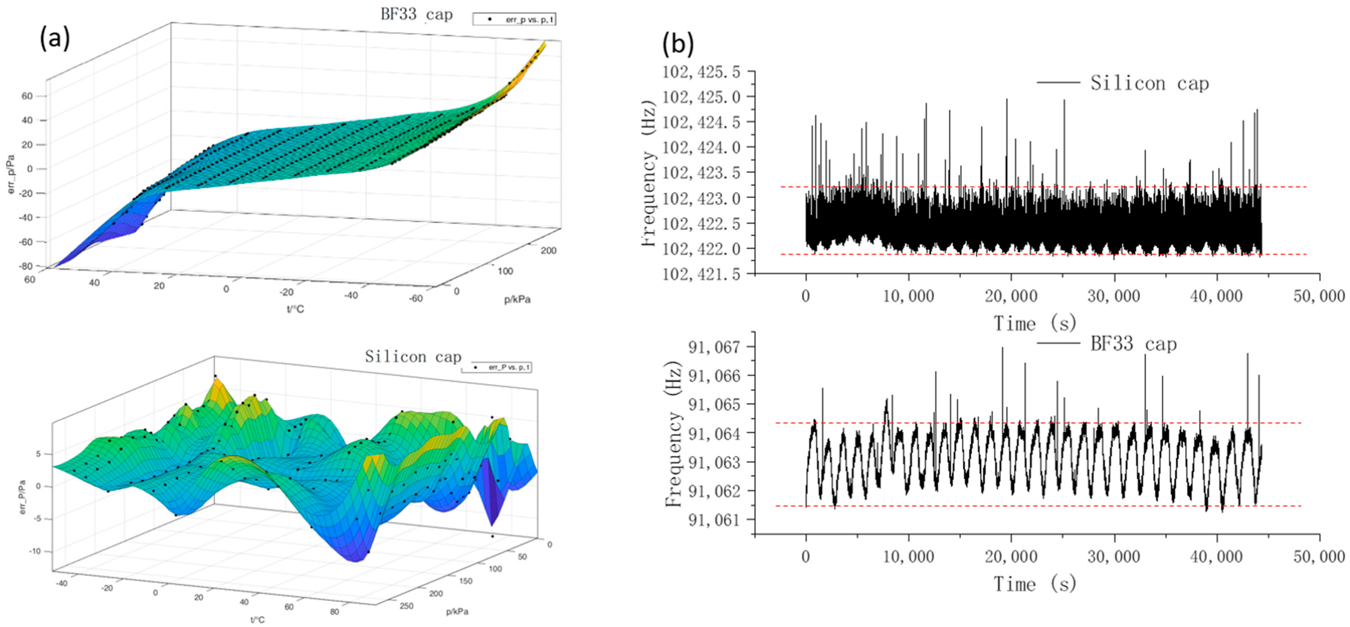
4.1. Pressure and Temperature Characterization
4.2. Accuracy and Stability
5. Conclusions
Author Contributions
Funding
Institutional Review Board Statement
Informed Consent Statement
Data Availability Statement
Conflicts of Interest
References
- Beeby, S.; Ensel, G.; White, N.M.; Kraft, M. MEMS Mechanical Sensors; Artech House: Boston, MA, USA; London, UK, 2004; pp. 1–5. [Google Scholar]
- Eaton, W.P.; Smith, J.H. Micromachined pressure sensors: Review and recent developments. J. Cit. Rep. 1997, 6, 530–539. [Google Scholar] [CrossRef]
- Harada, K.; Ikeda, K.; Kuwayama, H.; Murayama, H. Various applications of resonant pressure sensor chip based on 3-D micromachining. Sens. Actuators A Phys. 1999, 73, 261–266. [Google Scholar] [CrossRef]
- Lin, L.; Yun, W. MEMS pressure sensors for aerospace applications. In Proceedings of the IEEE Aerospace Conference, Aspen, CO, USA, 28 March 1998. [Google Scholar]
- Martin, W. Vacuum pressure measurement in semiconductor industry. In Proceedings of the 14th International Conference on Vacuum Science and Engineering Application, Shenyang, China, 4 August 2019. [Google Scholar]
- San, H.; Zhang, H.; Zhang, Q.; Yu, Y.; Chen, X. Silicon–glass-based single piezoresistive pressure sensors for harsh environment applications. J. Micromech. Microeng. 2013, 23, 075020. [Google Scholar] [CrossRef]
- Huang, X.; Zhang, D. A high sensitivity and high linearity pressure sensor based on a peninsula-structured diaphragm for low-pressure ranges. Sens. Actuators A Phys. 2014, 216, 176–189. [Google Scholar] [CrossRef]
- Kumar, S.S.; Pant, B. Design principles and considerations for the ‘ideal’ silicon piezoresistive pressure sensor: A focused review. Microsyst. Technol. 2014, 20, 1213–1247. [Google Scholar] [CrossRef]
- Sedlakova, V.; Sikula, J.; Vrba, R.; Majzner, J.; Sedlak, P.; Zarnik, M.S.; Belavic, D. Noise in piezoresistive pressure sensors. In Proceedings of the International Conference on Noise and Fluctuations, Xi’an, China, 2 June 2015. [Google Scholar]
- Xu, M.H.; Feng, Y.J.; Han, X.D.; Ke, X.; Li, G.; Zeng, Y.B.; Yan, H.P.; Li, D.T. Design and fabrication of an absolute pressure MEMS capacitance vacuum sensor based on silicon bonding technology. Vacuum 2021, 186, 110065. [Google Scholar] [CrossRef]
- Chavan, A.V.; Wise, K.D. Batch-processed vacuum-sealed capacitive pressure sensors. J. Microelectromech. Syst. 2001, 10, 580–588. [Google Scholar] [CrossRef]
- Ko, W.H.; Bao, B.H.; Hong, Y.D. High-sensitivity integrated circuit capacitive pressure transducer. IEEE Trans. Electron Devices 1982, 29, 48–56. [Google Scholar] [CrossRef]
- Li, Y.D.; Wang, J.B.; Luo, Z.Y.; Chen, D.Y.; Chen, J. A resonant pressure microsensor capable of self-temperature compensation. Sensors 2015, 15, 10048–10058. [Google Scholar] [CrossRef]
- Lu, Y.L.; Yan, P.C.; Xiang, C.; Chen, D.Y.; Wang, J.B.; Xie, B.; Chen, J. A resonant pressure microsensor with the measurement range of 1 MPa based on sensitivities balanced dual resonators. Sensors 2019, 19, 2272. [Google Scholar] [CrossRef] [Green Version]
- Welham, C.J.; Greenwood, J.; Bertioli, M.M. A high accuracy resonant pressure sensor by fusion bonding and trench etching. Sens. Actuators A, Phys. 1999, 76, 298–304. [Google Scholar] [CrossRef]
- Burns, D.W.; Zook, J.D.; Horning, R.D. Sealed-cavity resonant microbeam pressure sensor. Sens. Actuators A Phys. 1995, 48, 179–186. [Google Scholar] [CrossRef]
- Luo, Z.Y.; Chen, D.Y.; Wang, J.B.; Li, Y.D.; Chen, J. A high-Q resonant pressure microsensor with through-glass electrical interconnections based on wafer-level MEMS vacuum packaging. Sensors 2014, 14, 24244–24257. [Google Scholar] [CrossRef] [PubMed]
- Ma, Z.B.; Ren, S.; Qiao, D.Y.; Yuan, W.Z. Fabrication of a novel resonant pressure sensor based on SOI wafer. In Proceedings of the International Conference on Integration and Commercialization of Micro and Nanosystems, Hong Kong, China, 3 June 2008. [Google Scholar]
- Du, X.H.; Wang, L.Y.; Li, A.L.; Wang, L.Y.; Sun, D.H. High accuracy resonant pressure sensor with balanced-mass DETF resonator and twinborn diaphragm. J. Microelectromech. Syst. 2017, 26, 235–245. [Google Scholar] [CrossRef]
- Sun, X.D.; Yuan, W.Z.; Qiao, D.Y.; Sun, M.; Ren, S. Design and analysis of a new tuning fork structure for resonant pressure sensor. Micromachines 2016, 7, 148. [Google Scholar] [CrossRef] [PubMed]
- Samarao, A.K.; Ayazi, F. Temperature compensation of silicon resonators via degenerate doping. IEEE Trans. Electron Dev. 2011, 59, 87–93. [Google Scholar] [CrossRef]


Disclaimer/Publisher’s Note: The statements, opinions and data contained in all publications are solely those of the individual author(s) and contributor(s) and not of MDPI and/or the editor(s). MDPI and/or the editor(s) disclaim responsibility for any injury to people or property resulting from any ideas, methods, instructions or products referred to in the content. |
© 2023 by the authors. Licensee MDPI, Basel, Switzerland. This article is an open access article distributed under the terms and conditions of the Creative Commons Attribution (CC BY) license (https://creativecommons.org/licenses/by/4.0/).
Share and Cite
Chen, S.; Qin, J.; Lu, Y.; Xie, B.; Wang, J.; Chen, D.; Chen, J. An All-Silicon Resonant Pressure Microsensor Based on Eutectic Bonding. Micromachines 2023, 14, 441. https://doi.org/10.3390/mi14020441
Chen S, Qin J, Lu Y, Xie B, Wang J, Chen D, Chen J. An All-Silicon Resonant Pressure Microsensor Based on Eutectic Bonding. Micromachines. 2023; 14(2):441. https://doi.org/10.3390/mi14020441
Chicago/Turabian StyleChen, Siyuan, Jiaxin Qin, Yulan Lu, Bo Xie, Junbo Wang, Deyong Chen, and Jian Chen. 2023. "An All-Silicon Resonant Pressure Microsensor Based on Eutectic Bonding" Micromachines 14, no. 2: 441. https://doi.org/10.3390/mi14020441